EP1652737A2 - Airbag and airbag apparatus - Google Patents
Airbag and airbag apparatus Download PDFInfo
- Publication number
- EP1652737A2 EP1652737A2 EP05018686A EP05018686A EP1652737A2 EP 1652737 A2 EP1652737 A2 EP 1652737A2 EP 05018686 A EP05018686 A EP 05018686A EP 05018686 A EP05018686 A EP 05018686A EP 1652737 A2 EP1652737 A2 EP 1652737A2
- Authority
- EP
- European Patent Office
- Prior art keywords
- airbag
- base cloths
- sewn
- base
- portions
- Prior art date
- Legal status (The legal status is an assumption and is not a legal conclusion. Google has not performed a legal analysis and makes no representation as to the accuracy of the status listed.)
- Granted
Links
Images
Classifications
-
- B—PERFORMING OPERATIONS; TRANSPORTING
- B60—VEHICLES IN GENERAL
- B60R—VEHICLES, VEHICLE FITTINGS, OR VEHICLE PARTS, NOT OTHERWISE PROVIDED FOR
- B60R21/00—Arrangements or fittings on vehicles for protecting or preventing injuries to occupants or pedestrians in case of accidents or other traffic risks
- B60R21/02—Occupant safety arrangements or fittings, e.g. crash pads
- B60R21/16—Inflatable occupant restraints or confinements designed to inflate upon impact or impending impact, e.g. air bags
- B60R21/23—Inflatable members
- B60R21/235—Inflatable members characterised by their material
-
- B—PERFORMING OPERATIONS; TRANSPORTING
- B60—VEHICLES IN GENERAL
- B60R—VEHICLES, VEHICLE FITTINGS, OR VEHICLE PARTS, NOT OTHERWISE PROVIDED FOR
- B60R21/00—Arrangements or fittings on vehicles for protecting or preventing injuries to occupants or pedestrians in case of accidents or other traffic risks
- B60R21/02—Occupant safety arrangements or fittings, e.g. crash pads
- B60R21/16—Inflatable occupant restraints or confinements designed to inflate upon impact or impending impact, e.g. air bags
- B60R21/23—Inflatable members
- B60R21/235—Inflatable members characterised by their material
- B60R2021/23504—Inflatable members characterised by their material characterised by material
- B60R2021/23509—Fabric
- B60R2021/23514—Fabric coated fabric
-
- B—PERFORMING OPERATIONS; TRANSPORTING
- B60—VEHICLES IN GENERAL
- B60R—VEHICLES, VEHICLE FITTINGS, OR VEHICLE PARTS, NOT OTHERWISE PROVIDED FOR
- B60R21/00—Arrangements or fittings on vehicles for protecting or preventing injuries to occupants or pedestrians in case of accidents or other traffic risks
- B60R21/02—Occupant safety arrangements or fittings, e.g. crash pads
- B60R21/16—Inflatable occupant restraints or confinements designed to inflate upon impact or impending impact, e.g. air bags
- B60R21/23—Inflatable members
- B60R21/235—Inflatable members characterised by their material
- B60R2021/23571—Inflatable members characterised by their material characterised by connections between panels
- B60R2021/23576—Sewing
-
- B—PERFORMING OPERATIONS; TRANSPORTING
- B60—VEHICLES IN GENERAL
- B60R—VEHICLES, VEHICLE FITTINGS, OR VEHICLE PARTS, NOT OTHERWISE PROVIDED FOR
- B60R21/00—Arrangements or fittings on vehicles for protecting or preventing injuries to occupants or pedestrians in case of accidents or other traffic risks
- B60R21/02—Occupant safety arrangements or fittings, e.g. crash pads
- B60R21/16—Inflatable occupant restraints or confinements designed to inflate upon impact or impending impact, e.g. air bags
- B60R21/23—Inflatable members
- B60R21/235—Inflatable members characterised by their material
- B60R2021/23571—Inflatable members characterised by their material characterised by connections between panels
- B60R2021/23595—Sealing
Definitions
- the present invention relates to an airbag apparatus mounted in an automobile or the like and an airbag included in the airbag apparatus.
- a typical airbag apparatus mounted in a vehicle such as an automobile, includes an airbag and an inflator for inflating the airbag.
- an airbag When, for example, the vehicle collides, gas is discharged from the inflator and the airbag is inflated by the gas.
- the airbag is formed by sewing two base cloths together such that an inflatable chamber is provided between the base cloths.
- the sewn portions are often sealed by applying a sealant made of silicon resin or the like to the base cloths.
- a sealant made of silicon resin or the like to the base cloths.
- the manufacturing efficiency of the air bag is low since it takes a long time for the sealant to dry.
- Japanese Unexamined Patent Application Publication No. 8-301036 discloses an airbag including two circular base cloths constructed of thermofusible woven cloths of nylon, polyester, or the like.
- the base cloths are heat-sealed to each other at the outer periphery thereof, and are then sewn together at the inner periphery of the heat-sealed portions thereof.
- the base cloths are sewn at the inner periphery of the heat-sealed portions of the base cloth, and the sewn portions are not heat-sealed. Therefore, when the pressure in the airbag is increased, the sewn portions open and the airtightness between the sewn portions is reduced.
- An object of the present invention is to provide an airbag having a high airtightness at sewn portions and an airbag apparatus including the airbag.
- An airbag according to the present invention includes two base cloths that are sewn together such that an inflatable chamber is provided between the base cloths. At least one of the base cloths has a coating layer made of thermoplastic resin at least at the sewn portion thereof, and the sewn portions of the base cloths are adhered to each other by heat-sealing the coating layer.
- the sewn portions are adhered to each other by heat-sealing the coating layer and main bodies of the base cloths.
- an airbag apparatus includes the airbag structured as above.
- the sewn portions of the base cloths are adhered to each other by heat-sealing the coating layer. Therefore, the sewn portions are prevented from opening, and the airtightness between the sewn portions is high.
- the sewn portions of the base cloths may be adhered to each other by heat-sealing only the coating layer
- the main bodies of the base cloths may also be adhered by heat-sealing together with the coating layer.
- the overall bodies of the base cloths are adhered to each other by heat-sealing at the sewn portions thereof, and therefore the airtightness and strength of the airbag at the sewn portions are further increased.
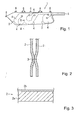
- Fig. 1 is a front view of an airbag according to the embodiment
- Fig. 2 is a sectional view of Fig. 1 taken along line II-II
- Fig. 3 is a sectional view of a base cloth.
- An airbag 1 is a curtain airbag disposed near a roof side rail of an automobile, and deploys downward along the inner sides of a door and a pillar of the automobile when the airbag 1 inflates.
- the airbag 1 is formed by sewing two base cloths 2 together with a sewing thread 3 such that chambers 4 are provided between the base cloths 2.
- a gas injection hole 5 is provided at an end of the airbag 1, and an inflator (not shown) is connected to the gas injection hole 5.
- the airbag 1 has projecting tabs 6 for attaching the airbag 1 to the roof side rail and an A pillar.
- the airbag 1 is folded into a long, thin shape, and is disposed so as to extend along the roof side rail. When gas is discharged from the inflator, the airbag 1 deploys downward along the door and the pillar as described above.
- each base cloth 2 includes a main body 2a made of a woven cloth and a coating layer 2b made of thermoplastic resin formed on one side of the main body 2a.
- the base cloths 2 are sewn together, one of the base cloths 2 is placed on the other in such a manner that the coating layers 2b of the base cloths 2 come into contact with each other, and then the base cloths 2 are adhered to each other by heating the portions to be sewn and by applying pressure to the base cloths as necessary.
- the base cloths 2 are sewn together at the portions to be sewn with the sewing thread 3.
- the base cloths 2 may also be sewn together with the sewing thread 3 before the coating layers 2b thereof are adhered to each other by heat-sealing. Thereby, an inflatable chamber 4 is formed between the base cloths 2.
- the airbag 1 structured as above the sewn portions of the base cloths 2 are adhered to each other by heat-sealing the coating layers 2b, and therefore the airbag 1 has high airtightness.
- a time required for heat-sealing is short, and therefore the airbag 1 can be manufactured with high efficiency.
- the airbag 1 is a curtain airbag in the above-described embodiment, the present invention may also be applied to other kinds of airbags, such as a passenger airbag, a driver airbag, and a side airbag.
- the coating layer extends over the entire area of each base cloth in the above-described embodiment, the coating layer may also be provided only at the portion to be sewn.
- each of the base cloths 2 includes the coating layer 2b in the above-described embodiment, the coating layer 2b may be provided in only one of the base cloths 2.
- the main bodies 2a are not heat-sealed in the above-described embodiment, the main bodies 2a may also be made of thermoplastic cloth material and be heat-sealed together with the coating layers 2b. In this case, the overall bodies of the base cloths are adhered to each other by heat-sealing at the sewn portions thereof, and therefore the airtightness and strength of the airbag at the sewn portions are further increased.
Landscapes
- Engineering & Computer Science (AREA)
- Mechanical Engineering (AREA)
- Air Bags (AREA)
Abstract
Description
- The present invention relates to an airbag apparatus mounted in an automobile or the like and an airbag included in the airbag apparatus.
- A typical airbag apparatus mounted in a vehicle, such as an automobile, includes an airbag and an inflator for inflating the airbag. When, for example, the vehicle collides, gas is discharged from the inflator and the airbag is inflated by the gas.
- Typically, the airbag is formed by sewing two base cloths together such that an inflatable chamber is provided between the base cloths.
- In order to increase the airtightness between the sewn portions of the base cloths, the sewn portions are often sealed by applying a sealant made of silicon resin or the like to the base cloths. However, the manufacturing efficiency of the air bag is low since it takes a long time for the sealant to dry.
- Japanese Unexamined Patent Application Publication No. 8-301036 discloses an airbag including two circular base cloths constructed of thermofusible woven cloths of nylon, polyester, or the like. The base cloths are heat-sealed to each other at the outer periphery thereof, and are then sewn together at the inner periphery of the heat-sealed portions thereof.
- In the airbag according to Japanese Unexamined Patent Application Publication No. 8-301036, the base cloths are sewn at the inner periphery of the heat-sealed portions of the base cloth, and the sewn portions are not heat-sealed. Therefore, when the pressure in the airbag is increased, the sewn portions open and the airtightness between the sewn portions is reduced.
- An object of the present invention is to provide an airbag having a high airtightness at sewn portions and an airbag apparatus including the airbag.
- The above object is achieved by an airbag according to Claim 1. The dependent claims define advantageous and preferred embodiments of the invention.
- An airbag according to the present invention includes two base cloths that are sewn together such that an inflatable chamber is provided between the base cloths. At least one of the base cloths has a coating layer made of thermoplastic resin at least at the sewn portion thereof, and the sewn portions of the base cloths are adhered to each other by heat-sealing the coating layer.
- According to a preferred embodiment, the sewn portions are adhered to each other by heat-sealing the coating layer and main bodies of the base cloths.
- In addition, an airbag apparatus according to the present invention includes the airbag structured as above.
- In the airbag according to the present invention, the sewn portions of the base cloths are adhered to each other by heat-sealing the coating layer. Therefore, the sewn portions are prevented from opening, and the airtightness between the sewn portions is high.
- Although the sewn portions of the base cloths may be adhered to each other by heat-sealing only the coating layer, the main bodies of the base cloths may also be adhered by heat-sealing together with the coating layer. In this case, the overall bodies of the base cloths are adhered to each other by heat-sealing at the sewn portions thereof, and therefore the airtightness and strength of the airbag at the sewn portions are further increased.
-
- Fig. 1 is a front view of an airbag according to an embodiment.
- Fig. 2 is a sectional view of Fig. 1 taken along line II-II.
- Fig. 3 is a sectional view of a base cloth.
- An embodiment will be described below with reference to the drawings. Fig. 1 is a front view of an airbag according to the embodiment, Fig. 2 is a sectional view of Fig. 1 taken along line II-II, and Fig. 3 is a sectional view of a base cloth.
- An airbag 1 is a curtain airbag disposed near a roof side rail of an automobile, and deploys downward along the inner sides of a door and a pillar of the automobile when the airbag 1 inflates.
- The airbag 1 is formed by sewing two
base cloths 2 together with asewing thread 3 such thatchambers 4 are provided between thebase cloths 2. Agas injection hole 5 is provided at an end of the airbag 1, and an inflator (not shown) is connected to thegas injection hole 5. The airbag 1 has projectingtabs 6 for attaching the airbag 1 to the roof side rail and an A pillar. The airbag 1 is folded into a long, thin shape, and is disposed so as to extend along the roof side rail. When gas is discharged from the inflator, the airbag 1 deploys downward along the door and the pillar as described above. - As shown in Fig. 3, each
base cloth 2 includes amain body 2a made of a woven cloth and acoating layer 2b made of thermoplastic resin formed on one side of themain body 2a. When thebase cloths 2 are sewn together, one of thebase cloths 2 is placed on the other in such a manner that thecoating layers 2b of thebase cloths 2 come into contact with each other, and then thebase cloths 2 are adhered to each other by heating the portions to be sewn and by applying pressure to the base cloths as necessary. Next, thebase cloths 2 are sewn together at the portions to be sewn with thesewing thread 3. Thebase cloths 2 may also be sewn together with thesewing thread 3 before thecoating layers 2b thereof are adhered to each other by heat-sealing. Thereby, aninflatable chamber 4 is formed between thebase cloths 2. - In the airbag 1 structured as above, the sewn portions of the
base cloths 2 are adhered to each other by heat-sealing thecoating layers 2b, and therefore the airbag 1 has high airtightness. In addition, a time required for heat-sealing is short, and therefore the airbag 1 can be manufactured with high efficiency. - Although the airbag 1 is a curtain airbag in the above-described embodiment, the present invention may also be applied to other kinds of airbags, such as a passenger airbag, a driver airbag, and a side airbag.
- In addition, although the coating layer extends over the entire area of each base cloth in the above-described embodiment, the coating layer may also be provided only at the portion to be sewn.
- In addition, although each of the
base cloths 2 includes thecoating layer 2b in the above-described embodiment, thecoating layer 2b may be provided in only one of thebase cloths 2. - In addition, although the
main bodies 2a are not heat-sealed in the above-described embodiment, themain bodies 2a may also be made of thermoplastic cloth material and be heat-sealed together with thecoating layers 2b. In this case, the overall bodies of the base cloths are adhered to each other by heat-sealing at the sewn portions thereof, and therefore the airtightness and strength of the airbag at the sewn portions are further increased.
Claims (3)
- An airbag (1) comprising two base cloths (2) that are sewn together such that an inflatable chamber is provided between the base cloths (2),
wherein at least one of the base cloths (2) has a coating layer (2b) made of thermoplastic resin at least at the sewn portion thereof, and
wherein the sewn portions of the base cloths (2) are adhered to each other by heat-sealing the coating layer (2b). - The airbag according to Claim 1, wherein the sewn portions are adhered to each other by heat-sealing the coating layer (2b) and main bodies (2a) of the base cloths.
- An airbag apparatus comprising the airbag according to one of Claims 1 and 2.
Applications Claiming Priority (1)
| Application Number | Priority Date | Filing Date | Title |
|---|---|---|---|
| JP2004314187A JP2006123696A (en) | 2004-10-28 | 2004-10-28 | Air bag and air bag device |
Publications (3)
| Publication Number | Publication Date |
|---|---|
| EP1652737A2 true EP1652737A2 (en) | 2006-05-03 |
| EP1652737A3 EP1652737A3 (en) | 2007-01-17 |
| EP1652737B1 EP1652737B1 (en) | 2008-10-08 |
Family
ID=35634736
Family Applications (1)
| Application Number | Title | Priority Date | Filing Date |
|---|---|---|---|
| EP05018686A Expired - Lifetime EP1652737B1 (en) | 2004-10-28 | 2005-08-29 | Airbag and airbag apparatus |
Country Status (5)
| Country | Link |
|---|---|
| US (1) | US20060091662A1 (en) |
| EP (1) | EP1652737B1 (en) |
| JP (1) | JP2006123696A (en) |
| CN (1) | CN100500480C (en) |
| DE (1) | DE602005010179D1 (en) |
Families Citing this family (5)
| Publication number | Priority date | Publication date | Assignee | Title |
|---|---|---|---|---|
| JP5187816B2 (en) | 2007-08-13 | 2013-04-24 | 芦森工業株式会社 | Airbag device |
| KR101655472B1 (en) * | 2010-08-18 | 2016-09-08 | 현대자동차주식회사 | Curtain airbag cushion and airbag module using the same |
| JP5505296B2 (en) * | 2010-12-28 | 2014-05-28 | 豊田合成株式会社 | Airbag |
| DE102011005549A1 (en) * | 2011-03-15 | 2011-07-21 | Takata-Petri Ag, 63743 | Side gas bag for vehicle occupant restraint system of motor vehicle, has inflatable chamber comprising head protection region and overlapping region and tapered from head protection region towards overlapping region |
| JP2013147279A (en) * | 2012-01-20 | 2013-08-01 | Daizo:Kk | Container body and method for manufacturing the same, and discharge container and discharge product using the container body |
Citations (1)
| Publication number | Priority date | Publication date | Assignee | Title |
|---|---|---|---|---|
| JPH08301036A (en) | 1995-05-09 | 1996-11-19 | Toyo Tire & Rubber Co Ltd | Air bag for vehicle and its manufacture |
Family Cites Families (17)
| Publication number | Priority date | Publication date | Assignee | Title |
|---|---|---|---|---|
| JPH0287653U (en) * | 1988-12-26 | 1990-07-11 | ||
| JPH0958387A (en) * | 1995-08-22 | 1997-03-04 | Achilles Corp | Air bag for vehicle and manufacture thereof |
| JPH09119066A (en) * | 1995-08-24 | 1997-05-06 | Bridgestone Corp | Air bag |
| DE19537702A1 (en) * | 1995-10-11 | 1997-04-17 | Hoechst Trevira Gmbh & Co Kg | Fabrics and scrims with adjustable gas and / or liquid tightness containing hybrid yarns, processes for their further processing, textile fabrics with predetermined gas and / or liquid permeability and their use |
| AU6641096A (en) * | 1996-04-05 | 1997-10-29 | Minnesota Mining And Manufacturing Company | Air bag fabric |
| JP3731266B2 (en) * | 1996-10-24 | 2006-01-05 | 豊田合成株式会社 | Method for manufacturing side airbag |
| JP2000016724A (en) * | 1998-07-06 | 2000-01-18 | Toyoda Spinning & Weaving Co Ltd | Elevator lifting air bag |
| US6734123B2 (en) * | 1999-06-07 | 2004-05-11 | Bradford Industries, Inc. | Polyurethane coated fabrics for use in air-holding vehicle restraint systems |
| JP3977552B2 (en) * | 1999-06-22 | 2007-09-19 | 芦森工業株式会社 | Airbag |
| US6299199B1 (en) * | 1999-09-17 | 2001-10-09 | Trw Vehicle Safety Systems Inc. | Inflatable side curtain |
| US6364356B1 (en) * | 1999-09-24 | 2002-04-02 | Milliken & Company | Airbag cushion comprising sewn reinforcement seams |
| JP2001097170A (en) * | 1999-09-30 | 2001-04-10 | Nippon Plast Co Ltd | Side air bag |
| JP2001097156A (en) * | 1999-09-30 | 2001-04-10 | Nippon Plast Co Ltd | Air bag for side part |
| US6350709B1 (en) * | 1999-11-30 | 2002-02-26 | Bradford Industries, Inc. | Heat sealable coated textile fabric for inflatable vehicle restraint systems |
| US6630220B1 (en) * | 2000-01-28 | 2003-10-07 | Bradford Industries, Inc. | Sewn fusion seal process for producing air-holding vehicle restraint systems |
| JP2001315610A (en) * | 2000-05-01 | 2001-11-13 | Nippon Plast Co Ltd | Air bag for side |
| JP2002144995A (en) * | 2000-11-09 | 2002-05-22 | Toray Ind Inc | Airbag |
-
2004
- 2004-10-28 JP JP2004314187A patent/JP2006123696A/en active Pending
-
2005
- 2005-08-29 DE DE602005010179T patent/DE602005010179D1/en not_active Expired - Lifetime
- 2005-08-29 EP EP05018686A patent/EP1652737B1/en not_active Expired - Lifetime
- 2005-10-13 US US11/248,236 patent/US20060091662A1/en not_active Abandoned
- 2005-10-28 CN CNB2005101184836A patent/CN100500480C/en not_active Expired - Fee Related
Patent Citations (1)
| Publication number | Priority date | Publication date | Assignee | Title |
|---|---|---|---|---|
| JPH08301036A (en) | 1995-05-09 | 1996-11-19 | Toyo Tire & Rubber Co Ltd | Air bag for vehicle and its manufacture |
Also Published As
| Publication number | Publication date |
|---|---|
| DE602005010179D1 (en) | 2008-11-20 |
| EP1652737A3 (en) | 2007-01-17 |
| CN100500480C (en) | 2009-06-17 |
| CN1765662A (en) | 2006-05-03 |
| JP2006123696A (en) | 2006-05-18 |
| EP1652737B1 (en) | 2008-10-08 |
| US20060091662A1 (en) | 2006-05-04 |
Similar Documents
| Publication | Publication Date | Title |
|---|---|---|
| US7980585B2 (en) | Airbag mounting assemblies with double-locking wrappers | |
| US6355123B1 (en) | Roll-over air bag having a reinforced perimeter seal and associated method for producing a flat reinforced seal in a roll-over air bag | |
| US6113141A (en) | Roll-over air bag | |
| US6969086B2 (en) | Airbag and airbag device | |
| US8820779B1 (en) | Inflatable airbag assembly with an internally mounted inflator | |
| US20040145161A1 (en) | Airbag and airbag apparatus | |
| US20110057422A1 (en) | Mounting assemblies with wrappers for inflatable curtain airbags | |
| US6431587B1 (en) | Inflatable side curtain | |
| US20020105173A1 (en) | Inflatable curtain cushion | |
| JPH11321535A (en) | Air bag for side air bag device | |
| JPH10109607A (en) | Side air bag | |
| US20030047919A1 (en) | Cushion for protection of a vehicle occupant's head | |
| US20070228709A1 (en) | Airbag with gas diffuser | |
| US6612612B2 (en) | Protective device for a motor vehicle | |
| US6409210B1 (en) | Integrated side air curtain and inflator overhead system | |
| JPH08142789A (en) | Air bag body for vehicle side part | |
| US20060033318A1 (en) | Side airbag and method of manufacture | |
| EP1256491B1 (en) | Head-protecting bag device for occupants in an automobile | |
| EP1652737A2 (en) | Airbag and airbag apparatus | |
| JP5314918B2 (en) | Air bag and air bag device | |
| US20060205302A1 (en) | Film lined airbag | |
| JP3724382B2 (en) | Vehicle airbag | |
| US6422591B1 (en) | Vehicle occupant protection apparatus | |
| US7255367B2 (en) | Air bag | |
| US20060138748A1 (en) | Head protecting airbag |
Legal Events
| Date | Code | Title | Description |
|---|---|---|---|
| PUAI | Public reference made under article 153(3) epc to a published international application that has entered the european phase |
Free format text: ORIGINAL CODE: 0009012 |
|
| AK | Designated contracting states |
Kind code of ref document: A2 Designated state(s): AT BE BG CH CY CZ DE DK EE ES FI FR GB GR HU IE IS IT LI LT LU LV MC NL PL PT RO SE SI SK TR |
|
| AX | Request for extension of the european patent |
Extension state: AL BA HR MK YU |
|
| PUAL | Search report despatched |
Free format text: ORIGINAL CODE: 0009013 |
|
| AK | Designated contracting states |
Kind code of ref document: A3 Designated state(s): AT BE BG CH CY CZ DE DK EE ES FI FR GB GR HU IE IS IT LI LT LU LV MC NL PL PT RO SE SI SK TR |
|
| AX | Request for extension of the european patent |
Extension state: AL BA HR MK YU |
|
| 17P | Request for examination filed |
Effective date: 20070620 |
|
| 17Q | First examination report despatched |
Effective date: 20070720 |
|
| AKX | Designation fees paid |
Designated state(s): DE FR GB SE |
|
| GRAP | Despatch of communication of intention to grant a patent |
Free format text: ORIGINAL CODE: EPIDOSNIGR1 |
|
| GRAS | Grant fee paid |
Free format text: ORIGINAL CODE: EPIDOSNIGR3 |
|
| GRAA | (expected) grant |
Free format text: ORIGINAL CODE: 0009210 |
|
| AK | Designated contracting states |
Kind code of ref document: B1 Designated state(s): DE FR GB SE |
|
| REG | Reference to a national code |
Ref country code: GB Ref legal event code: FG4D |
|
| REF | Corresponds to: |
Ref document number: 602005010179 Country of ref document: DE Date of ref document: 20081120 Kind code of ref document: P |
|
| PLBE | No opposition filed within time limit |
Free format text: ORIGINAL CODE: 0009261 |
|
| STAA | Information on the status of an ep patent application or granted ep patent |
Free format text: STATUS: NO OPPOSITION FILED WITHIN TIME LIMIT |
|
| PG25 | Lapsed in a contracting state [announced via postgrant information from national office to epo] |
Ref country code: SE Free format text: LAPSE BECAUSE OF FAILURE TO SUBMIT A TRANSLATION OF THE DESCRIPTION OR TO PAY THE FEE WITHIN THE PRESCRIBED TIME-LIMIT Effective date: 20090108 |
|
| 26N | No opposition filed |
Effective date: 20090709 |
|
| REG | Reference to a national code |
Ref country code: FR Ref legal event code: ST Effective date: 20100430 |
|
| PG25 | Lapsed in a contracting state [announced via postgrant information from national office to epo] |
Ref country code: FR Free format text: LAPSE BECAUSE OF NON-PAYMENT OF DUE FEES Effective date: 20090831 |
|
| PGFP | Annual fee paid to national office [announced via postgrant information from national office to epo] |
Ref country code: GB Payment date: 20120829 Year of fee payment: 8 |
|
| PGFP | Annual fee paid to national office [announced via postgrant information from national office to epo] |
Ref country code: DE Payment date: 20130821 Year of fee payment: 9 |
|
| GBPC | Gb: european patent ceased through non-payment of renewal fee |
Effective date: 20130829 |
|
| PG25 | Lapsed in a contracting state [announced via postgrant information from national office to epo] |
Ref country code: GB Free format text: LAPSE BECAUSE OF NON-PAYMENT OF DUE FEES Effective date: 20130829 |
|
| REG | Reference to a national code |
Ref country code: DE Ref legal event code: R119 Ref document number: 602005010179 Country of ref document: DE |
|
| REG | Reference to a national code |
Ref country code: DE Ref legal event code: R119 Ref document number: 602005010179 Country of ref document: DE Effective date: 20150303 |
|
| PG25 | Lapsed in a contracting state [announced via postgrant information from national office to epo] |
Ref country code: DE Free format text: LAPSE BECAUSE OF NON-PAYMENT OF DUE FEES Effective date: 20150303 |