EP1652704A1 - Electric heater assembly, especially for a motor vehicle - Google Patents
Electric heater assembly, especially for a motor vehicle Download PDFInfo
- Publication number
- EP1652704A1 EP1652704A1 EP04292584A EP04292584A EP1652704A1 EP 1652704 A1 EP1652704 A1 EP 1652704A1 EP 04292584 A EP04292584 A EP 04292584A EP 04292584 A EP04292584 A EP 04292584A EP 1652704 A1 EP1652704 A1 EP 1652704A1
- Authority
- EP
- European Patent Office
- Prior art keywords
- housing
- electric heating
- arrangement according
- heating arrangement
- electrical
- Prior art date
- Legal status (The legal status is an assumption and is not a legal conclusion. Google has not performed a legal analysis and makes no representation as to the accuracy of the status listed.)
- Granted
Links
Images


Classifications
-
- B—PERFORMING OPERATIONS; TRANSPORTING
- B60—VEHICLES IN GENERAL
- B60H—ARRANGEMENTS OF HEATING, COOLING, VENTILATING OR OTHER AIR-TREATING DEVICES SPECIALLY ADAPTED FOR PASSENGER OR GOODS SPACES OF VEHICLES
- B60H1/00—Heating, cooling or ventilating [HVAC] devices
- B60H1/22—Heating, cooling or ventilating [HVAC] devices the heat being derived otherwise than from the propulsion plant
- B60H1/2215—Heating, cooling or ventilating [HVAC] devices the heat being derived otherwise than from the propulsion plant the heat being derived from electric heaters
- B60H1/2225—Heating, cooling or ventilating [HVAC] devices the heat being derived otherwise than from the propulsion plant the heat being derived from electric heaters arrangements of electric heaters for heating air
-
- B—PERFORMING OPERATIONS; TRANSPORTING
- B60—VEHICLES IN GENERAL
- B60H—ARRANGEMENTS OF HEATING, COOLING, VENTILATING OR OTHER AIR-TREATING DEVICES SPECIALLY ADAPTED FOR PASSENGER OR GOODS SPACES OF VEHICLES
- B60H1/00—Heating, cooling or ventilating [HVAC] devices
- B60H1/22—Heating, cooling or ventilating [HVAC] devices the heat being derived otherwise than from the propulsion plant
- B60H2001/2268—Constructional features
- B60H2001/2278—Connectors, water supply, housing, mounting brackets
Definitions
- the invention relates to an electrical heating arrangement, in particular for a motor vehicle, according to the preamble of claim 1.
- a heating arrangement with a PTC element for passenger vehicles wherein an additional heater is provided with a radiator, which is flowed through in the operation of the additional heating of heating air, and at least one air outlet opening in the foot of a passenger compartment, to the the heating air is passed.
- the radiator is designed as an electric PTC element, which is arranged directly on the air outlet opening in the foot region.
- a PTC element in the form of a plurality of heating honeycombs is arranged in a plastic frame, not described in further detail, which encloses the air outlet opening. This can lead to problems with the electrical contact.
- an electrical heating arrangement in particular for a motor vehicle, is provided with an at least two-part housing, through which, if required, air to be heated flows, wherein at least one electrically operable heating element is arranged in the housing.
- positioning elements for electrical contacting are provided at least two locations in the housing, the electrical contact but arranged only on one of the points.
- the housing with a slightly modified heating element can be used for different applications requiring electrical contacting from different sides, so that only one tool has to be provided for the housing and, in addition, storage can be simplified.
- the heating element is mirror-symmetrical with respect to its center plane, so that it can be easily installed with reversed connection sides with the bottom up.
- the mirror-symmetrical embodiment preferably also relates to the electrical contacting of the heating element.
- the housing is preferably designed mirror-symmetrically with respect to a central transverse axis, and the locations with positioning elements for electrical contacting are preferably arranged at a distance from the central transverse axis on both sides of the housing.
- the electrical contacting of the heating element with a cable, in particular with a round cable, arranged in the housing the two parts of the housing are in particular connected by at least one clip connection, and the clip connection is arranged laterally of the electric heating element in the region of its electrical contact.
- the provided in the electrical contacting clip connections support the secure cohesion of the housing and thus also that the electrical connections do not solve even with a certain tensile load or a slight longitudinal displacement of the heating element, preferably a contact sleeve, which is part of the electrical contact , allows a certain length compensation.
- webs provided in the region of the electrical contacting are integrated into the housing, which fix the electrically contacting elements and prevent the electrical contact from loosening, so that reliable electrical contacting is possible.
- the webs are preferably arranged at an angle not equal to 0 ° and 90 °, in particular at an angle of 45 ° +/- 20 °, particularly preferably about 45 ° to the longitudinal direction of the contact sheets.
- the webs are also preferably arranged obliquely and offset relative to a cable bushing for the power cable, so that the guided through a cable bushing into the housing power cable is deflected at least at one point, whereby tensile loads can be absorbed.
- contact plate and power cable which is preferably a round cable
- electrical contact between contact plate and power cable is preferably carried out by means of a contact sleeve and optionally by means of an intermediate element which is arranged between the contact plate and contact sleeve and extends the contact plate.
- the contact sleeve is preferably arranged extending in the direction of the webs.
- the electric heating element comprises at least one PTC element.
- contact plates are preferably arranged on both sides of the PTC element, which serve for electrical contacting.
- the connection between contact plates and PTC element is preferably carried out by means of an adhesive connection.
- At least two contact plates are formed such that they are formed at one end as part of a plug, which projects laterally beyond the air-flow area with corrugated ribs for electrical contacting.
- the housing preferably has at least one insulating dividing wall, which ensures that a short circuit within the electrical heating element, that is to say in particular between two contact plates separated only by one PTC element, is avoided.
- the partition wall is in this case preferably formed both on the upper housing part and on the lower housing part, so that the separation of the contact plates is ensured even in a lateral region.
- the partitions of the centering of the upper housing part can serve on the lower housing part.
- the air duct housing in the region in which the electric heating element is arranged at least two parts designed as a plastic housing.
- a two-part design allows easy and quick installation with good strength properties.
- the housing can be easily manufactured by injection molding.
- the two housing parts are preferably connected to one another by means of clip connections, in particular also on the outside of the housing, so that no connecting elements protrude into the interior and influence the flow channel.
- an electric heater assembly in particular as additional heating, is provided for a motor vehicle heating and / or air conditioning device, which comprises at least one of the following components: heat exchanger, radiator, evaporator, filter, temperature mixing valve, mixing chamber, one or more flow channels and a or several control flaps for distributing the air to the outlet channels.
- the PTC elements 3 in one serving as a heater PTC heating arrangement 1 of a motor vehicle air conditioning system with a plurality of electrical heating element 2 in the form of a heating grid forming PTC elements 3, the PTC elements 3 in a known manner between two contact plates 4, 4 'glued, in this case by means a two-component silicone adhesive, wherein one of the contact plates, provided in the drawing by the reference numeral 4 ', is substantially rectangular in shape and forms with its laterally beyond the PTC element 3 projecting end part of an electrical contact 5.
- the designated by the reference numeral 4 contact plate is substantially rectangular in shape and arranged parallel to the other contact plate 4 '.
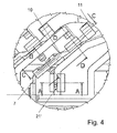
- the extended contact plate 4 'with an intermediate element 7 is firmly connected or optionally formed integrally, which is slightly narrower and at an angle of 45 ° to the contact plate 4 'extending tongue 8, on which an electrically contacting a contact sleeve 10 is pushed, which is electrically contacting firmly connected to a round cable 11 on the other side.
- the central longitudinal axis of the intermediate element 7 and the round cable 11 in the region clamped in the king pin 10 are in the present case aligned with one another (cf., FIG. 4).
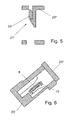
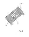
- the contact sleeve 10 is a metallic stamped and bent part and has three areas 10 ', 10 "and 10"', wherein the first area 10 'is pushed over the tongue 8 and in the elastically deformable areas of at least one flat side of the tongue. 8 spring-loaded under bias. Furthermore, end stops for the tongue 8 are provided between the first area 10 'and the middle, second area 10 "(see Fig. 7) . The middle, second area 10" (see Fig. 8) forms the transition to the third area 10 "', in which the contact sleeve 10 is pushed over the round cable 11.
- a two-part plastic housing 20 is arranged, which is arranged in an air duct of the motor vehicle air conditioner.
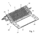
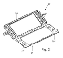
- the housing 20 is not divided in the middle, but, as shown for example in FIG. 1, the housing lower part 20 'forms the largest part of the housing 20, and the housing upper part 20 "is designed substantially as a lid, wherein the edges of the lid slightly behind This configuration of the housing parts 20 'and 20 "helps to avoid assembly errors.
- the housing 20 is embodied substantially mirror-symmetrically with respect to the central transverse axis, although in this case the electrical contacting takes place only on one side.
- the electrical contact can be provided accordingly also on the other side, so that a housing 20 can be used for various applications.
- the arrangement in the motor vehicle is present in the area below the front row of seats, so that the heating assembly 1, the air supplied to the second row of seats heated as needed.
- the two parts of the housing 20 are connected by means of clip connections 21 with the insert of the heating element 2 firmly together.
- the clip connections 21 additionally allow positioning during assembly.
- open cable bushings 22 are provided in the region of the corners in the longitudinal direction, wherein in the present case only one of the two mirror-symmetrical cable bushings 22 is used for a cable feedthrough (see Fig .. 1).
- positioning elements 23 are formed, which allow exact positioning of the corresponding areas and securely fix them in the assembled state of the housing 20.
- Protruding webs 24 'on the housing lower part 20' serve as positioning elements 23.
- the webs 24 'on the housing lower part 20' are designed in accordance with the course of the intermediate elements 7, ie angled at a 45 ° angle (see FIG Positioning between the lower housing part 20 'and the upper housing part 20 "further webs 24' on the housing lower part 20 'and webs 24" on the housing upper part 20 "are provided which are arranged substantially in the assembly direction aligned with each other and symmetrical to the central longitudinal axis of the contact sleeve 10 (see FIG. 7).
- clip connections 21 ' are also provided in the area between the electrical contacting of the contact plates 4' and the electrical contacting of the round cables 11, wherein four spring arms on the upper housing part 20 "and four undercuts cooperating with the lower housing part 20 'are formed in the present case.
- partitions 25 are formed, which hold the two arranged on the two sides of a PTC element 3 contact plates 4 and 4' or 4 spaced from each other and ensure that no short circuit occurs between them the partitions 25 extend in the housing lower part 20 "rib-like in the assembly direction, while the partitions 25 are formed in the upper housing part 20 'as protruding projections in the assembly direction.
- the electrical heating element 2 is positioned together with its electrical contact including the round cable 11 in the housing base 20 ', then the housing upper part 20' is placed and fixed by means of the clip connections 21 and 21 'on the housing base 20', so that the heating element 2 including the electrical contact of the same is securely and well fixed in the interior of the housing 20 is included.
Landscapes
- Physics & Mathematics (AREA)
- Thermal Sciences (AREA)
- Engineering & Computer Science (AREA)
- Mechanical Engineering (AREA)
- Air-Conditioning For Vehicles (AREA)
Abstract
Description
Die Erfindung betrifft eine elektrische Heizungsanordnung, insbesondere für ein Kraftfahrzeug, gemäß dem Oberbegriff des Anspruchs 1.The invention relates to an electrical heating arrangement, in particular for a motor vehicle, according to the preamble of
Aus der DE 101 44 757 A1 ist eine Heizungsanordnung mit einem PTC-Element für Personenfahrzeuge bekannt, wobei eine Zusatzheizung mit einem Heizkörper, der im Betrieb der Zusatzheizung von Heizluft durchströmt wird, und mit mindestens einer Luftaustrittsöffnung im Fußbereich eines Fahrgastraumes versehen ist, zu der die Heizluft geleitet wird. Um auf flexible Weise eine vertikale Temperaturschichtung im Fahrgastraum erzeugen zu können, die insbesondere auch an Sitzen im Fond als angenehm empfunden wird, ist der Heizkörper als ein elektrisches PTC-Element gestaltet, welches unmittelbar an der Luftaustrittsöffnung im Fußbereich angeordnet ist. Ein derartiger Zuheizer lässt noch Wünsche offen. Gemäß einem Ausführungsbeispiel ist ein PTC-Element in Gestalt mehrerer Heizwaben in einem nicht näher beschriebenen Kunststoff-Rahmen angeordnet, der die Luftaustrittsöffnung einfasst. Hierbei kann es zu Problemen bei der elektrischen Kontaktierung kommen.From DE 101 44 757 A1 discloses a heating arrangement with a PTC element for passenger vehicles is known, wherein an additional heater is provided with a radiator, which is flowed through in the operation of the additional heating of heating air, and at least one air outlet opening in the foot of a passenger compartment, to the the heating air is passed. In order to be able to produce a vertical temperature stratification in the passenger compartment in a flexible manner, which is particularly pleasant for seats in the rear, the radiator is designed as an electric PTC element, which is arranged directly on the air outlet opening in the foot region. Such a heater can still be desired. According to one exemplary embodiment, a PTC element in the form of a plurality of heating honeycombs is arranged in a plastic frame, not described in further detail, which encloses the air outlet opening. This can lead to problems with the electrical contact.
Es ist Aufgabe der Erfindung, eine verbesserte elektrische Heizungsanordnung zur Verfügung zu stellen, die eine sichere elektrische Kontaktierung auch bei großem Stromdurchfluss ermöglicht.It is an object of the invention to provide an improved electrical heating arrangement that enables safe electrical contact even at high current flow.
Diese Aufgabe wird gelöst durch eine elektrische Heizungsanordnung mit den Merkmalen des Anspruchs 1. Vorteilhafte Ausgestaltungen sind Gegenstand der Unteransprüche.This object is achieved by an electrical heating arrangement with the features of
Erfindungsgemäß ist eine elektrische Heizungsanordnung, insbesondere für ein Kraftfahrzeug, mit einem mindestens zweiteiligen Gehäuse vorgesehen, durch welches im Bedarfsfall zu erwärmende Luft strömt, wobei mindestens ein elektrisch betreibbares Heizelement im Gehäuse angeordnet ist. Hierbei sind an mindestens zwei Stellen im Gehäuse Positionierungselemente für eine elektrische Kontaktierung vorgesehen sind, die elektrische Kontaktierung aber nur auf einer der Stellen angeordnet. Dadurch kann das Gehäuse mit leicht modifiziertem Heizelement für unterschiedliche Anwendungsfälle, die eine elektrische Kontaktierung von verschiedenen Seiten erfordem, verwendet werden, so dass nur ein Werkzeug für das Gehäuse vorgesehen werden muss und zudem die Lagerhaltung vereinfacht werden kann. Bevorzugt ist hierbei das Heizelement bezüglich seiner Mittelebene spiegelsymmetrisch ausgebildet, so dass es bei vertauschten Anschlussseiten einfach mit der Unterseite nach oben eingebaut werden kann. Die spiegelsymmetrische Ausgestaltung bezieht sich bevorzugt auch auf die elektrische Kontaktierung des Heizelements.According to the invention, an electrical heating arrangement, in particular for a motor vehicle, is provided with an at least two-part housing, through which, if required, air to be heated flows, wherein at least one electrically operable heating element is arranged in the housing. Here, positioning elements for electrical contacting are provided at least two locations in the housing, the electrical contact but arranged only on one of the points. As a result, the housing with a slightly modified heating element can be used for different applications requiring electrical contacting from different sides, so that only one tool has to be provided for the housing and, in addition, storage can be simplified. Preferably, in this case, the heating element is mirror-symmetrical with respect to its center plane, so that it can be easily installed with reversed connection sides with the bottom up. The mirror-symmetrical embodiment preferably also relates to the electrical contacting of the heating element.
Das Gehäuse ist bevorzugt spiegelsymmetrisch bezüglich einer Mittelquerachse ausgebildet, und die Stellen mit Positionierungselementen für eine elektrische Kontaktierung sind bevorzugt beabstandet von der Mittelquerachse auf beiden Seiten des Gehäuses angeordnet. Mit einer derartigen Ausgestaltung sind die meisten Anwendungsfälle abgedeckt, da ein Kabel aus Bauraumgründen in der Regel um 90°, jedoch nicht immer 180° um das Gehäuse geführt werden kann.The housing is preferably designed mirror-symmetrically with respect to a central transverse axis, and the locations with positioning elements for electrical contacting are preferably arranged at a distance from the central transverse axis on both sides of the housing. With such a configuration, most applications are covered as a cable for reasons of space, usually by 90 °, but not always 180 ° can be performed around the housing.
Vorzugsweise ist die elektrische Kontaktierung des Heizelements mit einem Kabel, insbesondere mit einem Rundkabel, im Gehäuse angeordnet, die beiden Teile des Gehäuses sind insbesondere mittels mindestens einer Clipsverbindung miteinander verbunden, und die Clipsverbindung ist seitlich des elektrischen Heizelements im Bereich dessen elektrischer Kontaktierung angeordnet. Dabei unterstützen die im Bereich der elektrischen Kontaktierung vorgesehenen Clipsverbindungen den sicheren Zusammenhalt des Gehäuses und somit auch, dass sich die elektrischen Verbindungen auch bei einer gewissen Zugbelastung oder bei einer leichten Längsverschiebung des Heizelements nicht lösen, wobei vorzugsweise eine Kontakthülse, die Teil der elektrischen Kontaktierung ist, einen gewissen Längenausgleich ermöglicht.Preferably, the electrical contacting of the heating element with a cable, in particular with a round cable, arranged in the housing, the two parts of the housing are in particular connected by at least one clip connection, and the clip connection is arranged laterally of the electric heating element in the region of its electrical contact. The provided in the electrical contacting clip connections support the secure cohesion of the housing and thus also that the electrical connections do not solve even with a certain tensile load or a slight longitudinal displacement of the heating element, preferably a contact sleeve, which is part of the electrical contact , allows a certain length compensation.
Vorzugsweise sind im Bereich der elektrischen Kontaktierung vorgesehene Stege in das Gehäuse integriert, welche die elektrisch kontaktierenden Elemente fixieren und ein Lösen des elektrischen Kontakts verhindern, so dass eine sichere elektrische Kontaktierung möglich ist. Um Zugbelastungen am Kabel besser aufnehmen zu können, sind die Stege vorzugsweise in einem Winkel ungleich 0° und 90°, insbesondere in einem Winkel von 45° +/- 20°, insbesondere bevorzugt ca. 45°, zur Längsrichtung der Kontaktbleche angeordnet. Die Stege sind zudem bevorzugt schräg und versetzt bezüglich einer Kabeldurchführung für das Stromkabel angeordnet, so dass das durch eine Kabeldurchführung in das Gehäuse geführte Stromkabel mindestens an einer Stelle umgelenkt wird, wodurch Zugbelastungen aufgenommen werden können.Preferably, webs provided in the region of the electrical contacting are integrated into the housing, which fix the electrically contacting elements and prevent the electrical contact from loosening, so that reliable electrical contacting is possible. In order to better absorb tensile loads on the cable, the webs are preferably arranged at an angle not equal to 0 ° and 90 °, in particular at an angle of 45 ° +/- 20 °, particularly preferably about 45 ° to the longitudinal direction of the contact sheets. The webs are also preferably arranged obliquely and offset relative to a cable bushing for the power cable, so that the guided through a cable bushing into the housing power cable is deflected at least at one point, whereby tensile loads can be absorbed.
Die elektrische Kontaktierung zwischen Kontaktblech und Stromkabel, wobei es sich bevorzugt um ein Rundkabel handelt, erfolgt vorzugsweise mittels einer Kontakthülse und gegebenenfalls mittels eines Zwischenelements, das zwischen Kontaktblech und Kontakthülse angeordnet ist und das Kontaktblech verlängert. Dabei ist die Kontakthülse bevorzugt in Richtung der Stege verlaufend angeordnet.The electrical contact between contact plate and power cable, which is preferably a round cable, is preferably carried out by means of a contact sleeve and optionally by means of an intermediate element which is arranged between the contact plate and contact sleeve and extends the contact plate. In this case, the contact sleeve is preferably arranged extending in the direction of the webs.
Das elektrische Heizelement umfasst mindestens ein PTC-Element. Dabei sind vorzugsweise auf beiden Seiten des PTC-Elements Kontaktbleche angeordnet, welche der elektrischen Kontaktierung dienen. Die Verbindung zwischen Kontaktblechen und PTC-Element erfolgt vorzugsweise mittels einer Klebe-Verbindung.The electric heating element comprises at least one PTC element. In this case, contact plates are preferably arranged on both sides of the PTC element, which serve for electrical contacting. The connection between contact plates and PTC element is preferably carried out by means of an adhesive connection.
Auf der dem PTC-Element abgewandten Seite des Kontaktblechs ist bevorzugt eine Wellrippe sowie gegebenenfalls weitere Kontaktbleche, PTC-Elemente und Wellrippen mittels Klebe-Verbindungen, welche vorzugsweise durch einen Zwei-Komponenten-Silikon-Klebstoff gebildet sind, angebracht.On the side facing away from the PTC element of the contact sheet is preferably a corrugated fin and optionally further contact plates, PTC elements and corrugated ribs by means of adhesive compounds, which are preferably formed by a two-component silicone adhesive attached.
Mindestens zwei Kontaktbleche sind derart ausgebildet, dass sie an ihrem einen Ende als Teil eines Steckers ausgebildet sind, welcher zur elektrischen Kontaktierung seitlich über die von Luft durchströmte Fläche mit Wellrippen hinausragt.At least two contact plates are formed such that they are formed at one end as part of a plug, which projects laterally beyond the air-flow area with corrugated ribs for electrical contacting.
Das Gehäuse weist vorzugsweise mindestens eine isolierende Trennwand auf, welche sicherstellt, dass ein Kurzschluss innerhalb des elektrischen Heizelements, also insbesondere zwischen zwei nur von einem PTC-Element getrennten Kontaktblechen, vermieden wird. Die Trennwand ist hierbei bevorzugt sowohl am Gehäuseoberteil als auch am Gehäuseunterteil ausgebildet, so dass die Trennung der Kontaktbleche auch in einem seitlichen Bereich sichergestellt ist. Zudem können die Trennwände der Zentrierung des Gehäuseoberteils auf dem Gehäuseunterteil dienen.The housing preferably has at least one insulating dividing wall, which ensures that a short circuit within the electrical heating element, that is to say in particular between two contact plates separated only by one PTC element, is avoided. The partition wall is in this case preferably formed both on the upper housing part and on the lower housing part, so that the separation of the contact plates is ensured even in a lateral region. In addition, the partitions of the centering of the upper housing part can serve on the lower housing part.
Bevorzugt ist das Luftkanal-Gehäuse im Bereich, in welchem das elektrische Heizelement angeordnet ist, mindestens zweiteilig als Kunststoffgehäuse ausgebildet. Eine zweiteilige Ausgestaltung ermöglicht eine einfache und schnelle Montage bei guten Festigkeitseigenschaften. Ferner lässt sich das Gehäuse einfach mittels Spritzgießens herstellen. Die beiden Gehäuseteile sind bevorzugt mittels Clipsverbindungen, insbesondere auch auf der Gehäuseaußenseite, miteinander verbunden, so dass keine Verbindungselemente in den Innenraum ragen und den Strömungskanal beeinflussen.Preferably, the air duct housing in the region in which the electric heating element is arranged, at least two parts designed as a plastic housing. A two-part design allows easy and quick installation with good strength properties. Furthermore, the housing can be easily manufactured by injection molding. The two housing parts are preferably connected to one another by means of clip connections, in particular also on the outside of the housing, so that no connecting elements protrude into the interior and influence the flow channel.
Vorteilhafterweise ist eine erfindungsgemäße elektrische Heizungsanordnung, insbesondere als Zusatzheizung, für eine Kraftfahrzeug- Heizungs- und/oder Klimatisierungseinrichtung vorgesehen, wobei diese zumindest eines der folgenden Bauteile umfasst: Wärmetauscher, Heizkörper, Verdampfer, Filter, Temperaturmischklappe, Mischkammer, einen oder mehrere Strömungskanäle und eine oder mehrere Steuerklappen zur Verteilung der Luft auf die Austrittskanäle.Advantageously, an electric heater assembly according to the invention, in particular as additional heating, is provided for a motor vehicle heating and / or air conditioning device, which comprises at least one of the following components: heat exchanger, radiator, evaporator, filter, temperature mixing valve, mixing chamber, one or more flow channels and a or several control flaps for distributing the air to the outlet channels.
Im Folgenden wird die Erfindung anhand eines Ausführungsbeispiels unter Bezugnahme auf die Zeichnung im Einzelnen erläutert. In der Zeichnung zeigen:
- Fig. 1
- eine perspektivische Ansicht auf eine erfindungsgemäβe Heizungsanordnung mit geöffnetem Gehäuse,
- Fig. 2
- eine Fig. 1 entsprechende Ansicht des Gehäuses,
- Fig. 3
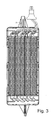
- eine Draufsicht auf das offene Gehäuse mit der Heizungsanordnung,
- Fig. 4
- eine Detaildarstellung des Bereichs Z1 von Fig. 3,
- Fig. 5
- einen Schnitt entlang Linie A-A in Fig. 4,
- Fig. 6
- einen Schnitt entlang Linie B-B in Fig. 4,
- Fig. 7
- einen Schnitt entlang Linie C-C in Fig. 4,
- Fig. 8
- einen Schnitt entlang Linie D-D in Fig. 4, und
- Fig. 9
- eine vergrößerte Darstellung des oberen Bereichs von Fig. 3.
- Fig. 1
- a perspective view of a erfindungsgemäβe heater assembly with the housing open,
- Fig. 2
- 1 corresponding view of the housing,
- Fig. 3
- a plan view of the open housing with the heater assembly,
- Fig. 4
- a detailed representation of the area Z1 of FIG. 3,
- Fig. 5
- a section along line AA in Fig. 4,
- Fig. 6
- a section along line BB in Fig. 4,
- Fig. 7
- a section along line CC in Fig. 4,
- Fig. 8
- a section along line DD in Fig. 4, and
- Fig. 9
- an enlarged view of the upper portion of Fig. 3rd
Bei einer als Zuheizer dienenden PTC-Heizungsanordnung 1 einer Kraftfahrzeug-Klimaanlage mit mehreren ein elektrisches Heizelement 2 in Form eines Heizgitters bildenden PTC-Elementen 3 sind die PTC-Elemente 3 auf an sich bekannte Weise zwischen zwei Kontaktblechen 4, 4' eingeklebt, vorliegend mittels eines Zwei-Komponenten-Silikon-Klebstoffes, wobei eines der Kontaktbleche, in der Zeichnung mit dem Bezugszeichen 4' versehen, im Wesentlichen rechteckförmig ausgebildet ist und mit seinem seitlich über das PTC-Element 3 überstehenden Ende einen Teil eines elektrischen Kontakts 5 bildet. Das mit dem Bezugszeichen 4 bezeichnete Kontaktblech ist im Wesentlichen rechteckförmig ausgebildet und parallel zum anderen Kontaktblech 4' angeordnet.In one serving as a heater
Auf den jeweils dem PTC-Element 3 gegenüberliegenden Seiten der Kontaktbleche 4 und 4' sind mittels einer entsprechenden Klebe-Verbindung Wellrippen 6 angebracht und an diesen, ebenfalls wiederum mit einer entsprechenden Klebe-Verbindung je ein weiteres Kontaktblech 4 und 4', wobei diese Kontaktbleche den zuvor beschriebenen Kontaktblechen 4 und 4' entsprechen.On each of the
Für die Herstellung eines elektrischen Kontakts ist das verlängerte Kontaktblech 4' mit einem Zwischenelement 7 fest verbunden oder gegebenenfalls einstückig ausgebildet, welches etwas schmäler ausgebildet ist und eine in einem Winkel von 45° zum Kontaktblech 4' verlaufende Zunge 8 aufweist, auf welche elektrisch kontaktierend eine Kontakthülse 10 aufgeschoben ist, die auf der anderen Seite elektrisch kontaktierend fest mit einem Rundkabel 11 verbunden ist. Die Mittellängsachse des Zwischenelements 7 und dem Rundkabel 11 im in der Köntakthülse 10 eingespannten Bereich fluchten vorliegend miteinander (vgl. Fig. 4). Die Kontakthülse 10 ist ein metallisches Stanzbiegeteil und weist drei Bereiche 10', 10" und 10"' auf, wobei der erste Bereich 10' über die Zunge 8 geschoben ist und in dem elastisch verformbare Bereiche die von zumindest einer Flachseite her an der Zunge 8 federnd unter Vorspannung anliegen. Ferner sind zwischen dem ersten Bereich 10' und dem mittleren, zweiten Bereich 10" Endanschläge für die Zunge 8 vorgesehen (vgl. Fig. 7). Der mittlere, zweite Bereich 10" (vgl. Fig. 8) bildet den Übergang zum dritten Bereich 10"', in welchem die Kontakthülse 10 über das Rundkabel 11 geschoben ist.For the production of an electrical contact, the extended contact plate 4 'with an
Um die zuvor beschriebene Anordnung herum ist ein zweiteiliges Kunststoff-Gehäuse 20 angeordnet, welches in einem Luftführungskanal der Kraftfahrzeug-Klimaanlage angeordnet ist. Dabei ist das Gehäuse 20 nicht mittig geteilt, sondern, wie beispielsweise aus Fig. 1 ersichtlich, das Gehäuseunterteil 20' bildet den größten Teil des Gehäuses 20, und das Gehäuseoberteil 20" ist im Wesentlichen als Deckel ausgestaltet, wobei die Ränder des Deckels leicht nach unten heruntergezogen sind. Diese Ausgestaltung der Gehäuseteile 20' und 20" hilft Zusammenbaufehler zu vermeiden. Das Gehäuse 20 ist vorliegend im Wesentlichen spiegelsymmetrisch zur Mittelquerachse ausgebildet, wobei jedoch die elektrische Kontaktierung vorliegend nur auf einer Seite erfolgt. Auf Grund der spiegelsymmetrischen Ausgestaltung kann die elektrische Kontaktierung entsprechend auch auf der anderen Seite vorgesehen sein, so dass ein Gehäuse 20 für verschiedene Anwendungen benutzt werden kann. Die Anordnung im Kraftfahrzeug ist vorliegend im Bereich unterhalb der vorderen Sitzreihe, so dass die Heizungsanordnung 1 die der zweiten Sitzreihe zugeführte Luft bei Bedarf erwärmt.Around the arrangement described above, a two-
Die beiden Teile des Gehäuses 20 sind mittels Clipsverbindungen 21 unter Einlage des Heizelements 2 fest miteinander verbunden. Die Clipsverbindungen 21 ermöglichen zusätzlich eine Positionierung im Rahmen der Montage. Zur Durchführung der Rundkabel 11 sind im Bereich der Ecken in Längsrichtung offene Kabeldurchführungen 22 vorgesehen, wobei vorliegend nur eine der beiden spiegelsymmetrischen Kabeldurchführungen 22 für eine Kabeldurchführung verwendet ist (vgl. Fig. 1).The two parts of the
Im Bereich zwischen der elektrischen Kontaktierung der Kontaktbleche 4' und der elektrischen Kontaktierung der Rundkabel 11 sind am Gehäuseunterteil 20' und am Gehäuseoberteil 20" Positionierungselemente 23 ausgebildet, welche eine exakte Positionierung der entsprechenden Bereiche ermöglichen und diese im zusammengebauten Zustand des Gehäuses 20 sicher fixieren. Als Positionierungselemente 23 dienen vorstehende Stege 24' am Gehäuseunterteil 20'. Die Stege 24' am Gehäuseunterteil 20' sind entsprechend dem Verlauf der Zwischenelemente 7, also in einem 45°-Winkel abgewinkelt, ausgebildet (vgl. Fig. 2). Ferner sind zur Positionierung zwischen dem Gehäuseunterteil 20' und dem Gehäuseoberteil 20" weitere Stege 24' am Gehäuseunterteil 20' und Stege 24" am Gehäuseoberteil 20" vorgesehen, die im Wesentlichen in Zusammenbaurichtung miteinander fluchtend und symmetrisch zur Mittellängsachse der Kontakthülse 10 angeordnet sind (vgl. Fig. 7).In the area between the electrical contact of the contact plates 4 'and the electrical contacting of the
Um die Fixierung optimal zu sichern sind auch im Bereich zwischen der elektrischen Kontaktierung der Kontaktbleche 4' und der elektrischen Kontaktierung der Rundkabel 11 Clipsverbindungen 21' vorgesehen, wobei vorliegend vier Federarme am Gehäuseoberteil 20" und vier hiermit zusammenwirkende Hinterschneidungen am Gehäuseunterteil 20' ausgebildet sind.In order to optimally secure the fixation, clip connections 21 'are also provided in the area between the electrical contacting of the contact plates 4' and the electrical contacting of the
Diese Clipsverbindungen 21' am Gehäuse 20 bilden eine Art Verschlusssystem zur Sicherung der elektrischen Kontaktierung. Die schräge Anordnung der Stege 24' und 24" stellen auch bei einer gewissen Zugbelastung sicher, dass die elektrische Kontaktierung des Heizelements 2 mit Hilfe der Kontakthülse 10 nicht gestört wird.These clip connections 21 'on the
Ferner sind am Gehäuseunterteil 20' und am Gehäuseoberteil 20" vorstehende Trennwände 25 ausgebildet, welche die beiden auf den beiden Seiten eines PTC-Elements 3 angeordneten Kontaktbleche 4 und 4' oder 4 voneinander beabstandet halten und sicherstellen, dass zwischen denselben kein Kurzschluss auftritt. Hierbei verlaufen die Trennwände 25 im Gehäuseunterteil 20" rippenartig in Zusammenbaurichtung, während die Trennwände 25 im Gehäuseoberteil 20' als in Zusammenbaurichtung vorstehende Vorsprünge ausgebildet sind.Furthermore, on the lower housing part 20 'and on the
Für den Zusammenbau wird das elektrische Heizelement 2 mitsamt seiner elektrischen Kontaktierung einschließlich der Rundkabel 11 im Gehäuseunterteil 20' positioniert, anschließend wird das Gehäuseoberteil 20" aufgesetzt und mit Hilfe der Clipsverbindungen 21 und 21' am Gehäuseunterteil 20' fixiert, so dass das Heizelement 2 einschließlich der elektrischen Kontaktierung desselben sicher und gut fixiert im Inneren des Gehäuses 20 eingeschlossen ist.For assembly, the
- 11
- HeizungsanordnungHeating arrangement
- 22
- Heizelementheating element
- 33
- PTC-ElementPTC element
- 44
- Kontaktblechcontact sheet
- 4'4 '
- verlängertes Kontaktblechextended contact sheet
- 55
- elektrischer Kontaktelectric contact
- 66
- Wellrippecorrugated fin
- 77
- Zwischenelementintermediate element
- 88th
- Zungetongue
- 1010
- Kontakthülsecontact sleeve
- 10'10 '
- erster Bereichfirst area
- 10"10 "
- zweiter Bereichsecond area
- 10"'10 " '
- dritter Bereichthird area
- 1111
- Rundkabelround cable
- 2020
- Gehäusecasing
- 20'20 '
- Gehäuseteil, GehäuseunterteilHousing part, housing lower part
- 20"20 "
- Gehäuseteil, GehäuseoberteilHousing part, housing top
- 21, 21'21, 21 '
- Clipsverbindungclip connection
- 2222
- KabeldurchführungGrommet
- 2323
- Positionierungselementpositioner
- 24',24"24 ', 24 "
- Stegweb
- 2525
- Trennwandpartition wall
Claims (18)
Priority Applications (3)
| Application Number | Priority Date | Filing Date | Title |
|---|---|---|---|
| AT04292584T ATE380695T1 (en) | 2004-10-29 | 2004-10-29 | ELECTRICAL HEATING ARRANGEMENT, PARTICULARLY FOR A MOTOR VEHICLE |
| EP04292584A EP1652704B1 (en) | 2004-10-29 | 2004-10-29 | Electric heater assembly, especially for a motor vehicle |
| DE502004005712T DE502004005712D1 (en) | 2004-10-29 | 2004-10-29 | Electric heating arrangement, in particular for a motor vehicle |
Applications Claiming Priority (1)
| Application Number | Priority Date | Filing Date | Title |
|---|---|---|---|
| EP04292584A EP1652704B1 (en) | 2004-10-29 | 2004-10-29 | Electric heater assembly, especially for a motor vehicle |
Publications (2)
| Publication Number | Publication Date |
|---|---|
| EP1652704A1 true EP1652704A1 (en) | 2006-05-03 |
| EP1652704B1 EP1652704B1 (en) | 2007-12-12 |
Family
ID=34931494
Family Applications (1)
| Application Number | Title | Priority Date | Filing Date |
|---|---|---|---|
| EP04292584A Not-in-force EP1652704B1 (en) | 2004-10-29 | 2004-10-29 | Electric heater assembly, especially for a motor vehicle |
Country Status (3)
| Country | Link |
|---|---|
| EP (1) | EP1652704B1 (en) |
| AT (1) | ATE380695T1 (en) |
| DE (1) | DE502004005712D1 (en) |
Cited By (2)
| Publication number | Priority date | Publication date | Assignee | Title |
|---|---|---|---|---|
| EP2017547A1 (en) | 2007-07-18 | 2009-01-21 | Catem GmbH & Co. KG | Electric heating device |
| DE102008050481A1 (en) * | 2008-07-21 | 2010-01-28 | Beru Ag | Vehicle heating system, vehicle air conditioning system with heating device and method for mounting a heating device |
Citations (6)
| Publication number | Priority date | Publication date | Assignee | Title |
|---|---|---|---|---|
| FR2742384A1 (en) * | 1995-12-19 | 1997-06-20 | Valeo Climatisation | Heating and ventilating device for passenger space of motor vehicle |
| EP0876080A1 (en) * | 1997-05-02 | 1998-11-04 | Réalisations et Diffusion pour l'Industrie (R.D.I) | Heating device having resistive elements with a positive temperature coefficient (PTC) |
| EP0901311A2 (en) * | 1997-09-02 | 1999-03-10 | Behr GmbH & Co. | Electric heating apparatus, particularly for vehicle |
| DE10144757A1 (en) | 2001-09-11 | 2003-03-27 | Webasto Thermosysteme Gmbh | Additional heating for passenger vehicles |
| DE10241763A1 (en) * | 2002-09-10 | 2004-03-18 | Horst Knappe | Heating panel for e.g. underfloor heating systems is made from natural stone and has transverse grooves, in which heating pipe is mounted and held in position by flexible strips on either side |
| DE20218331U1 (en) * | 2002-11-25 | 2004-04-01 | Alloc A/S | Heated floor panel |
-
2004
- 2004-10-29 EP EP04292584A patent/EP1652704B1/en not_active Not-in-force
- 2004-10-29 DE DE502004005712T patent/DE502004005712D1/en active Active
- 2004-10-29 AT AT04292584T patent/ATE380695T1/en not_active IP Right Cessation
Patent Citations (6)
| Publication number | Priority date | Publication date | Assignee | Title |
|---|---|---|---|---|
| FR2742384A1 (en) * | 1995-12-19 | 1997-06-20 | Valeo Climatisation | Heating and ventilating device for passenger space of motor vehicle |
| EP0876080A1 (en) * | 1997-05-02 | 1998-11-04 | Réalisations et Diffusion pour l'Industrie (R.D.I) | Heating device having resistive elements with a positive temperature coefficient (PTC) |
| EP0901311A2 (en) * | 1997-09-02 | 1999-03-10 | Behr GmbH & Co. | Electric heating apparatus, particularly for vehicle |
| DE10144757A1 (en) | 2001-09-11 | 2003-03-27 | Webasto Thermosysteme Gmbh | Additional heating for passenger vehicles |
| DE10241763A1 (en) * | 2002-09-10 | 2004-03-18 | Horst Knappe | Heating panel for e.g. underfloor heating systems is made from natural stone and has transverse grooves, in which heating pipe is mounted and held in position by flexible strips on either side |
| DE20218331U1 (en) * | 2002-11-25 | 2004-04-01 | Alloc A/S | Heated floor panel |
Cited By (2)
| Publication number | Priority date | Publication date | Assignee | Title |
|---|---|---|---|---|
| EP2017547A1 (en) | 2007-07-18 | 2009-01-21 | Catem GmbH & Co. KG | Electric heating device |
| DE102008050481A1 (en) * | 2008-07-21 | 2010-01-28 | Beru Ag | Vehicle heating system, vehicle air conditioning system with heating device and method for mounting a heating device |
Also Published As
| Publication number | Publication date |
|---|---|
| DE502004005712D1 (en) | 2008-01-24 |
| ATE380695T1 (en) | 2007-12-15 |
| EP1652704B1 (en) | 2007-12-12 |
Similar Documents
| Publication | Publication Date | Title |
|---|---|---|
| EP2017548B1 (en) | Electric heating device, in particular for motor vehicles | |
| EP1800520B1 (en) | Electrical heating arrangement, especially for a motor vehicle | |
| EP3079442B1 (en) | Electrical heating device and frame for same | |
| DE112016000688B4 (en) | Electric heater | |
| DE10044379A1 (en) | Component for a motor vehicle | |
| EP1523226B1 (en) | Heating assembly with PTC elements, particularly for motor vehicles | |
| DE102013000628B4 (en) | Holding frame of a fresh air flap of a motor vehicle and fresh air flap with holding frame | |
| EP1621378B2 (en) | Heating device with one heating element, in particular for a vehicle | |
| EP2407327B1 (en) | Electric heating device, in particular additional motor vehicle heating and motor vehicle air conditioning device | |
| DE4420673B4 (en) | Connector attachment assembly | |
| DE102014205744A1 (en) | Control unit for a vehicle heater | |
| EP3374234A1 (en) | Securing system | |
| EP1652704B1 (en) | Electric heater assembly, especially for a motor vehicle | |
| EP1522439B2 (en) | Heater with PTC element, particulary for a motor vehicle | |
| EP1691579A1 (en) | Electric heater, in particular for a motor vehicle | |
| EP1652703B1 (en) | Electric heating device for a vehicle | |
| DE102017105048B4 (en) | Battery carrier for a vehicle | |
| EP1486363B1 (en) | Heating arrangement comprising a ptc element, in particular for a vehicle | |
| DE3210019A1 (en) | HOUSING FOR A HEATING OR AIR CONDITIONING FOR MOTOR VEHICLES | |
| DE112016000677B4 (en) | Electric heater and air circulating duct in a ventilation, heating and/or air conditioning system | |
| DE102010046315A1 (en) | Air-conditioning apparatus for motor car, has clamping rib provided between wall portions and insert, and deformable and/or shearable from plate-type vaporizer and insert, during mounting of apparatus | |
| EP1340637B1 (en) | Heat exchange device | |
| EP1621826B1 (en) | Heating arrangement with PTC-Element, in particular for a vehicle | |
| EP3557155B1 (en) | Electric heating device | |
| DE19834390C1 (en) | Air guide casing for motor vehicle air conditioning |
Legal Events
| Date | Code | Title | Description |
|---|---|---|---|
| PUAI | Public reference made under article 153(3) epc to a published international application that has entered the european phase |
Free format text: ORIGINAL CODE: 0009012 |
|
| AK | Designated contracting states |
Kind code of ref document: A1 Designated state(s): AT BE BG CH CY CZ DE DK EE ES FI FR GB GR HU IE IT LI LU MC NL PL PT RO SE SI SK TR |
|
| AX | Request for extension of the european patent |
Extension state: AL HR LT LV MK |
|
| 17P | Request for examination filed |
Effective date: 20061103 |
|
| AKX | Designation fees paid |
Designated state(s): AT BE BG CH CY CZ DE DK EE ES FI FR GB GR HU IE IT LI LU MC NL PL PT RO SE SI SK TR |
|
| GRAP | Despatch of communication of intention to grant a patent |
Free format text: ORIGINAL CODE: EPIDOSNIGR1 |
|
| GRAS | Grant fee paid |
Free format text: ORIGINAL CODE: EPIDOSNIGR3 |
|
| GRAA | (expected) grant |
Free format text: ORIGINAL CODE: 0009210 |
|
| AK | Designated contracting states |
Kind code of ref document: B1 Designated state(s): AT BE BG CH CY CZ DE DK EE ES FI FR GB GR HU IE IT LI LU MC NL PL PT RO SE SI SK TR |
|
| REG | Reference to a national code |
Ref country code: GB Ref legal event code: FG4D Free format text: NOT ENGLISH |
|
| REG | Reference to a national code |
Ref country code: CH Ref legal event code: EP |
|
| REG | Reference to a national code |
Ref country code: IE Ref legal event code: FG4D Free format text: LANGUAGE OF EP DOCUMENT: GERMAN |
|
| REF | Corresponds to: |
Ref document number: 502004005712 Country of ref document: DE Date of ref document: 20080124 Kind code of ref document: P |
|
| REG | Reference to a national code |
Ref country code: SE Ref legal event code: TRGR |
|
| PG25 | Lapsed in a contracting state [announced via postgrant information from national office to epo] |
Ref country code: SI Free format text: LAPSE BECAUSE OF FAILURE TO SUBMIT A TRANSLATION OF THE DESCRIPTION OR TO PAY THE FEE WITHIN THE PRESCRIBED TIME-LIMIT Effective date: 20071212 Ref country code: FI Free format text: LAPSE BECAUSE OF FAILURE TO SUBMIT A TRANSLATION OF THE DESCRIPTION OR TO PAY THE FEE WITHIN THE PRESCRIBED TIME-LIMIT Effective date: 20071212 Ref country code: PL Free format text: LAPSE BECAUSE OF FAILURE TO SUBMIT A TRANSLATION OF THE DESCRIPTION OR TO PAY THE FEE WITHIN THE PRESCRIBED TIME-LIMIT Effective date: 20071212 Ref country code: NL Free format text: LAPSE BECAUSE OF FAILURE TO SUBMIT A TRANSLATION OF THE DESCRIPTION OR TO PAY THE FEE WITHIN THE PRESCRIBED TIME-LIMIT Effective date: 20071212 |
|
| NLV1 | Nl: lapsed or annulled due to failure to fulfill the requirements of art. 29p and 29m of the patents act | ||
| GBV | Gb: ep patent (uk) treated as always having been void in accordance with gb section 77(7)/1977 [no translation filed] | ||
| PG25 | Lapsed in a contracting state [announced via postgrant information from national office to epo] |
Ref country code: ES Free format text: LAPSE BECAUSE OF FAILURE TO SUBMIT A TRANSLATION OF THE DESCRIPTION OR TO PAY THE FEE WITHIN THE PRESCRIBED TIME-LIMIT Effective date: 20080323 |
|
| ET | Fr: translation filed | ||
| PG25 | Lapsed in a contracting state [announced via postgrant information from national office to epo] |
Ref country code: RO Free format text: LAPSE BECAUSE OF FAILURE TO SUBMIT A TRANSLATION OF THE DESCRIPTION OR TO PAY THE FEE WITHIN THE PRESCRIBED TIME-LIMIT Effective date: 20071212 Ref country code: SK Free format text: LAPSE BECAUSE OF FAILURE TO SUBMIT A TRANSLATION OF THE DESCRIPTION OR TO PAY THE FEE WITHIN THE PRESCRIBED TIME-LIMIT Effective date: 20071212 |
|
| PG25 | Lapsed in a contracting state [announced via postgrant information from national office to epo] |
Ref country code: PT Free format text: LAPSE BECAUSE OF FAILURE TO SUBMIT A TRANSLATION OF THE DESCRIPTION OR TO PAY THE FEE WITHIN THE PRESCRIBED TIME-LIMIT Effective date: 20080512 |
|
| REG | Reference to a national code |
Ref country code: IE Ref legal event code: FD4D |
|
| PLBE | No opposition filed within time limit |
Free format text: ORIGINAL CODE: 0009261 |
|
| STAA | Information on the status of an ep patent application or granted ep patent |
Free format text: STATUS: NO OPPOSITION FILED WITHIN TIME LIMIT |
|
| PG25 | Lapsed in a contracting state [announced via postgrant information from national office to epo] |
Ref country code: IE Free format text: LAPSE BECAUSE OF FAILURE TO SUBMIT A TRANSLATION OF THE DESCRIPTION OR TO PAY THE FEE WITHIN THE PRESCRIBED TIME-LIMIT Effective date: 20071212 Ref country code: DK Free format text: LAPSE BECAUSE OF FAILURE TO SUBMIT A TRANSLATION OF THE DESCRIPTION OR TO PAY THE FEE WITHIN THE PRESCRIBED TIME-LIMIT Effective date: 20071212 |
|
| 26N | No opposition filed |
Effective date: 20080915 |
|
| PG25 | Lapsed in a contracting state [announced via postgrant information from national office to epo] |
Ref country code: GB Free format text: LAPSE BECAUSE OF FAILURE TO SUBMIT A TRANSLATION OF THE DESCRIPTION OR TO PAY THE FEE WITHIN THE PRESCRIBED TIME-LIMIT Effective date: 20071212 |
|
| PG25 | Lapsed in a contracting state [announced via postgrant information from national office to epo] |
Ref country code: GR Free format text: LAPSE BECAUSE OF FAILURE TO SUBMIT A TRANSLATION OF THE DESCRIPTION OR TO PAY THE FEE WITHIN THE PRESCRIBED TIME-LIMIT Effective date: 20080313 |
|
| BERE | Be: lapsed |
Owner name: BEHR FRANCE ROUFFACH SAS Effective date: 20081031 |
|
| PG25 | Lapsed in a contracting state [announced via postgrant information from national office to epo] |
Ref country code: EE Free format text: LAPSE BECAUSE OF FAILURE TO SUBMIT A TRANSLATION OF THE DESCRIPTION OR TO PAY THE FEE WITHIN THE PRESCRIBED TIME-LIMIT Effective date: 20071212 Ref country code: BG Free format text: LAPSE BECAUSE OF FAILURE TO SUBMIT A TRANSLATION OF THE DESCRIPTION OR TO PAY THE FEE WITHIN THE PRESCRIBED TIME-LIMIT Effective date: 20080312 |
|
| PG25 | Lapsed in a contracting state [announced via postgrant information from national office to epo] |
Ref country code: MC Free format text: LAPSE BECAUSE OF NON-PAYMENT OF DUE FEES Effective date: 20081031 |
|
| REG | Reference to a national code |
Ref country code: CH Ref legal event code: PL |
|
| PG25 | Lapsed in a contracting state [announced via postgrant information from national office to epo] |
Ref country code: CY Free format text: LAPSE BECAUSE OF FAILURE TO SUBMIT A TRANSLATION OF THE DESCRIPTION OR TO PAY THE FEE WITHIN THE PRESCRIBED TIME-LIMIT Effective date: 20071212 |
|
| PG25 | Lapsed in a contracting state [announced via postgrant information from national office to epo] |
Ref country code: BE Free format text: LAPSE BECAUSE OF NON-PAYMENT OF DUE FEES Effective date: 20081031 |
|
| PG25 | Lapsed in a contracting state [announced via postgrant information from national office to epo] |
Ref country code: LI Free format text: LAPSE BECAUSE OF NON-PAYMENT OF DUE FEES Effective date: 20081031 Ref country code: CH Free format text: LAPSE BECAUSE OF NON-PAYMENT OF DUE FEES Effective date: 20081031 |
|
| PG25 | Lapsed in a contracting state [announced via postgrant information from national office to epo] |
Ref country code: AT Free format text: LAPSE BECAUSE OF NON-PAYMENT OF DUE FEES Effective date: 20081029 |
|
| PGFP | Annual fee paid to national office [announced via postgrant information from national office to epo] |
Ref country code: IT Payment date: 20091028 Year of fee payment: 6 |
|
| PG25 | Lapsed in a contracting state [announced via postgrant information from national office to epo] |
Ref country code: LU Free format text: LAPSE BECAUSE OF NON-PAYMENT OF DUE FEES Effective date: 20081029 Ref country code: HU Free format text: LAPSE BECAUSE OF FAILURE TO SUBMIT A TRANSLATION OF THE DESCRIPTION OR TO PAY THE FEE WITHIN THE PRESCRIBED TIME-LIMIT Effective date: 20080613 |
|
| PG25 | Lapsed in a contracting state [announced via postgrant information from national office to epo] |
Ref country code: TR Free format text: LAPSE BECAUSE OF FAILURE TO SUBMIT A TRANSLATION OF THE DESCRIPTION OR TO PAY THE FEE WITHIN THE PRESCRIBED TIME-LIMIT Effective date: 20071212 |
|
| PGFP | Annual fee paid to national office [announced via postgrant information from national office to epo] |
Ref country code: CZ Payment date: 20100927 Year of fee payment: 7 |
|
| PGFP | Annual fee paid to national office [announced via postgrant information from national office to epo] |
Ref country code: SE Payment date: 20101020 Year of fee payment: 7 |
|
| PG25 | Lapsed in a contracting state [announced via postgrant information from national office to epo] |
Ref country code: IT Free format text: LAPSE BECAUSE OF NON-PAYMENT OF DUE FEES Effective date: 20101029 |
|
| REG | Reference to a national code |
Ref country code: SE Ref legal event code: EUG |
|
| PG25 | Lapsed in a contracting state [announced via postgrant information from national office to epo] |
Ref country code: CZ Free format text: LAPSE BECAUSE OF NON-PAYMENT OF DUE FEES Effective date: 20111029 |
|
| PG25 | Lapsed in a contracting state [announced via postgrant information from national office to epo] |
Ref country code: SE Free format text: LAPSE BECAUSE OF NON-PAYMENT OF DUE FEES Effective date: 20111030 |
|
| REG | Reference to a national code |
Ref country code: DE Ref legal event code: R082 Ref document number: 502004005712 Country of ref document: DE Representative=s name: GRAUEL, ANDREAS, DIPL.-PHYS. DR. RER. NAT., DE Ref country code: DE Ref legal event code: R081 Ref document number: 502004005712 Country of ref document: DE Owner name: MAHLE INTERNATIONAL GMBH, DE Free format text: FORMER OWNER: BEHR FRANCE ROUFFACH S.A.S., ROUFFACH, FR |
|
| REG | Reference to a national code |
Ref country code: FR Ref legal event code: PLFP Year of fee payment: 12 |
|
| REG | Reference to a national code |
Ref country code: FR Ref legal event code: PLFP Year of fee payment: 13 |
|
| REG | Reference to a national code |
Ref country code: FR Ref legal event code: PLFP Year of fee payment: 14 |
|
| REG | Reference to a national code |
Ref country code: FR Ref legal event code: PLFP Year of fee payment: 15 |
|
| PGFP | Annual fee paid to national office [announced via postgrant information from national office to epo] |
Ref country code: DE Payment date: 20181030 Year of fee payment: 15 |
|
| PGFP | Annual fee paid to national office [announced via postgrant information from national office to epo] |
Ref country code: FR Payment date: 20181026 Year of fee payment: 15 |
|
| REG | Reference to a national code |
Ref country code: DE Ref legal event code: R119 Ref document number: 502004005712 Country of ref document: DE |
|
| PG25 | Lapsed in a contracting state [announced via postgrant information from national office to epo] |
Ref country code: DE Free format text: LAPSE BECAUSE OF NON-PAYMENT OF DUE FEES Effective date: 20200501 |
|
| PG25 | Lapsed in a contracting state [announced via postgrant information from national office to epo] |
Ref country code: FR Free format text: LAPSE BECAUSE OF NON-PAYMENT OF DUE FEES Effective date: 20191031 |