EP1652632A1 - Removable chuck with extended retainer ring - Google Patents
Removable chuck with extended retainer ring Download PDFInfo
- Publication number
- EP1652632A1 EP1652632A1 EP05023348A EP05023348A EP1652632A1 EP 1652632 A1 EP1652632 A1 EP 1652632A1 EP 05023348 A EP05023348 A EP 05023348A EP 05023348 A EP05023348 A EP 05023348A EP 1652632 A1 EP1652632 A1 EP 1652632A1
- Authority
- EP
- European Patent Office
- Prior art keywords
- gripping
- drill bit
- housing
- user
- sleeve
- Prior art date
- Legal status (The legal status is an assumption and is not a legal conclusion. Google has not performed a legal analysis and makes no representation as to the accuracy of the status listed.)
- Withdrawn
Links
- 230000007246 mechanism Effects 0.000 claims abstract description 27
- 230000014759 maintenance of location Effects 0.000 claims abstract description 14
- 230000004913 activation Effects 0.000 claims description 8
- 210000003811 finger Anatomy 0.000 claims description 5
- 210000003813 thumb Anatomy 0.000 claims description 5
- 230000003213 activating effect Effects 0.000 claims description 3
- 230000004048 modification Effects 0.000 description 2
- 238000012986 modification Methods 0.000 description 2
- 230000004075 alteration Effects 0.000 description 1
- 238000013016 damping Methods 0.000 description 1
Images

Classifications
-
- B—PERFORMING OPERATIONS; TRANSPORTING
- B23—MACHINE TOOLS; METAL-WORKING NOT OTHERWISE PROVIDED FOR
- B23B—TURNING; BORING
- B23B31/00—Chucks; Expansion mandrels; Adaptations thereof for remote control
- B23B31/02—Chucks
- B23B31/10—Chucks characterised by the retaining or gripping devices or their immediate operating means
- B23B31/12—Chucks with simultaneously-acting jaws, whether or not also individually adjustable
- B23B31/1207—Chucks with simultaneously-acting jaws, whether or not also individually adjustable moving obliquely to the axis of the chuck in a plane containing this axis
-
- B—PERFORMING OPERATIONS; TRANSPORTING
- B23—MACHINE TOOLS; METAL-WORKING NOT OTHERWISE PROVIDED FOR
- B23Q—DETAILS, COMPONENTS, OR ACCESSORIES FOR MACHINE TOOLS, e.g. ARRANGEMENTS FOR COPYING OR CONTROLLING; MACHINE TOOLS IN GENERAL CHARACTERISED BY THE CONSTRUCTION OF PARTICULAR DETAILS OR COMPONENTS; COMBINATIONS OR ASSOCIATIONS OF METAL-WORKING MACHINES, NOT DIRECTED TO A PARTICULAR RESULT
- B23Q3/00—Devices holding, supporting, or positioning work or tools, of a kind normally removable from the machine
- B23Q3/12—Devices holding, supporting, or positioning work or tools, of a kind normally removable from the machine for securing to a spindle in general
-
- B—PERFORMING OPERATIONS; TRANSPORTING
- B25—HAND TOOLS; PORTABLE POWER-DRIVEN TOOLS; MANIPULATORS
- B25F—COMBINATION OR MULTI-PURPOSE TOOLS NOT OTHERWISE PROVIDED FOR; DETAILS OR COMPONENTS OF PORTABLE POWER-DRIVEN TOOLS NOT PARTICULARLY RELATED TO THE OPERATIONS PERFORMED AND NOT OTHERWISE PROVIDED FOR
- B25F3/00—Associations of tools for different working operations with one portable power-drive means; Adapters therefor
-
- B—PERFORMING OPERATIONS; TRANSPORTING
- B23—MACHINE TOOLS; METAL-WORKING NOT OTHERWISE PROVIDED FOR
- B23B—TURNING; BORING
- B23B2231/00—Details of chucks, toolholder shanks or tool shanks
- B23B2231/38—Keyless chucks for hand tools
-
- Y—GENERAL TAGGING OF NEW TECHNOLOGICAL DEVELOPMENTS; GENERAL TAGGING OF CROSS-SECTIONAL TECHNOLOGIES SPANNING OVER SEVERAL SECTIONS OF THE IPC; TECHNICAL SUBJECTS COVERED BY FORMER USPC CROSS-REFERENCE ART COLLECTIONS [XRACs] AND DIGESTS
- Y10—TECHNICAL SUBJECTS COVERED BY FORMER USPC
- Y10T—TECHNICAL SUBJECTS COVERED BY FORMER US CLASSIFICATION
- Y10T408/00—Cutting by use of rotating axially moving tool
- Y10T408/94—Tool-support
- Y10T408/95—Tool-support with tool-retaining means
Definitions
- the present invention relates to power tools and. more particularly, to removable chucks for drills.
- the present invention provides the art with a removable chuck which includes a drill bit chucking member which has an extended sleeve.
- the extended sleeve provides a substantial area to enable the user to torque down a bit within the chuck.
- the present invention provides a removable adaptor which includes a gripping surface. The gripping surface enables the user to grip the adaptor to provide a counter force when the extended sleeve is being torqued down to secure a bit.
- the present invention negates the need for an internal spindle lock on the power tool.
- a removable chuck which comprises a drill bit receiving member which includes a mechanism to receive a drill bit.
- the drill bit receiving member has an inner sleeve and an outer sleeve.
- the outer sleeve is rotatable about the inner sleeve to tighten a drill bit in the receiving member.
- the outer sleeve has a desired length to provide a gripping surface which enables the surface to be gripped by a substantial portion of a user's hand.
- a mechanism to retain the chuck on a shaft of a power tool is coupled with the receiving member.
- the retaining mechanism includes a housing and a shaft retention mechanism within the housing. The housing is directly coupled with the inner sleeve of the tool bit receiving member.
- the housing has an outer surface with a desired length and a gripping member.
- the gripping member enables a user to provide a counter force on the housing when a drill bit is tightened in the drill bit receiving mechanism.
- the outer sleeve includes a gripping member on its outer surface which is substantially similar to the gripping member on the housing.
- the outer sleeve has a length which enables gripping by a user's index, middle and ring finger, as well as the user's thumb.
- a power tool comprises a housing with a motor within the housing.
- An output, with a shaft, is coupled with the motor.
- a power source is coupled with the motor.
- An activation member is coupled with the motor and power source for activating and deactivating the motor which, in turn, drives the output shaft.
- a removable chuck is coupled with the shaft.
- the removable chuck includes a drill bit receiving member which includes a mechanism to receive a drill bit.
- the drill bit receiving member has an inner sleeve and an outer sleeve. The outer sleeve is rotatable about the inner sleeve to tighten a drill bit in the receiving member.
- the outer sleeve has a desired length to provide a gripping surface which enables the surface to be gripped by a substantial portion of a user's hand.
- a mechanism to retain the chuck on a shaft of a power tool is coupled with the receiving member.
- the retaining mechanism includes a housing and a shaft retention mechanism within the housing.
- the housing is directly coupled with the inner sleeve of the tool bit receiving member.
- the housing has an outer surface with a desired length and a gripping member.
- the gripping member enables a user to provide a counter force on the housing when a drill bit is tightened in the drill bit receiving mechanism.
- the outer sleeve includes a gripping member on its outer surface which is substantially similar to the gripping member on the housing.
- the outer sleeve has a length which enables gripping by a user's index, middle and ring finger, as well as the user's thumb.
- the power tool 10 is illustrated as a drill.
- the power tool 10 includes a clamshell housing 12 which surrounds a motor 14.
- the housing 12 includes a handle 16 which includes a power source 18 coupled with the handle.
- the power source 18 is shown as a battery, however, an AC cord could be used.
- An activation member 20 is electrically coupled with the motor 14 and power source 18.
- the activation member 20 energizes and de-energizes the motor 14.
- the motor 14 is coupled with an outlet 22 which includes a shaft 24.
- the shaft 24 is coupled with a removable chuck 30.
- the motor drives the output which, in turn, drives the shaft 24 which rotates the removable chuck 30.
- the removable chuck 30 includes a bit retaining portion 32 and a shaft retention portion 34.
- the bit retaining portion 32 indudes an outer member 36, an inner member 38 and jaws 40.
- the outer member 36 is rotatably connected to the inner member 38 by conventional means.
- the outer member 36 has an extended sleeve 42 which provides an enlarged gripping surface.
- the sleeve 42 includes gripping members 44 which may include elongated raised and lowered portions which enable a user to grip the sleeve 42.
- the sleeve 42 has a desired length such that it can be gripped by a substantial portion of the user's hand. Ordinarily, the sleeve 42 has a length such that the user can position his index, middle and ring finger onto the sleeve. Also, the thumb would wrap around the bottom of the sleeve as illustrated in phantom.
- the sleeve 42 has a significant surface area which enables the user to apply a significant amount of torque onto the sleeve 42 which, in turn, securely fastens the drill bit into the drill bit receiving mechanism 32, via the damping of the jaws 40.
- the jaws 40 and inner member 38 are like those known in the art.
- the inner surface of the outer sleeve 42 includes threads for moving the jaws 40 which is conventional in the art.
- a rear sleeve 46 is coupled with the shaft retention portion 34.
- the rear sleeve 46 is secured to an inner sleeve of the shaft retention portion 34.
- the rear sleeve 46 could be fixed to the housing 48.
- the rear sleeve 46 enables the bit retaining portion 32 to be rotated with respect to the rear sleeve 46. With the rear sleeve 46 being attached to the shaft retention portion, the bit retaining portion 32 can be gripped and rotated in one direction while the shaft retaining portion 34, with the rear sleeve 46, can be rotated in the other direction eliminating the need for a spindle lock.
- the rear sleeve 46 includes an outer annular wall 47 and an inner annular wall 49.
- the outer annular wall 47 provides a continuous appearance with the bit retaining portion outer member 36.
- the inner annular wall 49 enables the sleeve to be secured with an inner sleeve of the shaft retention portion 34.
- the outer surface of the outer annular wall 47 may include a gripping surface like that of the outer member 36.
- the shaft retention portion 34 includes a housing 48, an activation member 50 and a securement mechanism 52.
- the housing 48 includes a gripping surface 54.
- the gripping surface 54 has elongated raised and lower portions and is substantially identical to the gripping portion of the outer sleeve 42. This provides an aesthetically pleasing appearance to the removable chuck.
- the gripping surface 54 on the housing 48 enables a user to apply a counter force on the removable chuck 30 when the outer member 34 is being turned to torque down a drill bit in the jaws 40.
- the counter force supplied by the gripping surface 54 enables the power tool to eliminate the need for an internal spindle lock in the tool.
- a spindle lock feature of the tool can be eliminated.
- the activation member 50 and shaft retention member 52 are like those shown in U.S. Patent Nos. 6,551,037, 6,550,786, 6,079,716, 5,951,026, 6,239,559, 6,047,971 the specification and drawings of which are herein expressly incorporated by reference.
- the retention member 52 secures with the shaft 24 to rotate the removable chuck 30 with the output of the drill 10.
- Activation member 50 enables the removable chuck 30 to be released from the shaft 24.
- the removable chuck 30 provides front 44 and rear 54 gripping surfaces.
- the removable chuck 30 enables the bit retaining portion 32 to provide the majority of the front grip while the shaft retention portion 34 provides a majority of the rear counter grip. This provides a significant gripping surface on each portion which enables the user to exert additional force to tighten down drill bits more effectively in the chuck.
Landscapes
- Engineering & Computer Science (AREA)
- Mechanical Engineering (AREA)
- Drilling And Boring (AREA)
- Gripping On Spindles (AREA)
Abstract
Description
- The present invention relates to power tools and. more particularly, to removable chucks for drills.
- Various types of removable chucks for drills exist in the prior art. U.S. Patent Nos. 6,551,037, 6.550.786, 6,079,716, 5,951,026, 6,239,559, 6,047,971, all assigned to the assignee of the present invention disclose various types of removable chucks. These removable chucks work satisfactory for their intended purpose. However, designers strive to improve the art.
- The present invention provides the art with a removable chuck which includes a drill bit chucking member which has an extended sleeve. The extended sleeve provides a substantial area to enable the user to torque down a bit within the chuck. The present invention provides a removable adaptor which includes a gripping surface. The gripping surface enables the user to grip the adaptor to provide a counter force when the extended sleeve is being torqued down to secure a bit. The present invention negates the need for an internal spindle lock on the power tool.
- It is an aspect of the invention to have a removable chuck which comprises a drill bit receiving member which includes a mechanism to receive a drill bit. The drill bit receiving member has an inner sleeve and an outer sleeve. The outer sleeve is rotatable about the inner sleeve to tighten a drill bit in the receiving member. The outer sleeve has a desired length to provide a gripping surface which enables the surface to be gripped by a substantial portion of a user's hand. A mechanism to retain the chuck on a shaft of a power tool is coupled with the receiving member. The retaining mechanism includes a housing and a shaft retention mechanism within the housing. The housing is directly coupled with the inner sleeve of the tool bit receiving member. The housing has an outer surface with a desired length and a gripping member. The gripping member enables a user to provide a counter force on the housing when a drill bit is tightened in the drill bit receiving mechanism. The outer sleeve includes a gripping member on its outer surface which is substantially similar to the gripping member on the housing. The outer sleeve has a length which enables gripping by a user's index, middle and ring finger, as well as the user's thumb.
- According to another aspect of the invention, a power tool comprises a housing with a motor within the housing. An output, with a shaft, is coupled with the motor. A power source is coupled with the motor. An activation member is coupled with the motor and power source for activating and deactivating the motor which, in turn, drives the output shaft. A removable chuck is coupled with the shaft. The removable chuck includes a drill bit receiving member which includes a mechanism to receive a drill bit. The drill bit receiving member has an inner sleeve and an outer sleeve. The outer sleeve is rotatable about the inner sleeve to tighten a drill bit in the receiving member. The outer sleeve has a desired length to provide a gripping surface which enables the surface to be gripped by a substantial portion of a user's hand. A mechanism to retain the chuck on a shaft of a power tool is coupled with the receiving member. The retaining mechanism includes a housing and a shaft retention mechanism within the housing. The housing is directly coupled with the inner sleeve of the tool bit receiving member. The housing has an outer surface with a desired length and a gripping member. The gripping member enables a user to provide a counter force on the housing when a drill bit is tightened in the drill bit receiving mechanism. The outer sleeve includes a gripping member on its outer surface which is substantially similar to the gripping member on the housing. The outer sleeve has a length which enables gripping by a user's index, middle and ring finger, as well as the user's thumb.
- From the following detailed description taken in conjunction with the subjoined drawings and accompanying claims, other objects and advantages will become apparent to those skilled in the art.
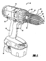
- Figure 1 is an elevation view of a power tool including a removable chuck in accordance with the present invention.
- Figure 2 is an enlarged perspective view partially in section of the removable chuck in Figure 1.
- Tuming to Figure 1, a power tool is illustrated and designated with the reference numeral 10. The power tool 10 is illustrated as a drill. The power tool 10 includes a
clamshell housing 12 which surrounds a motor 14. Thehousing 12 includes a handle 16 which includes apower source 18 coupled with the handle. Thepower source 18 is shown as a battery, however, an AC cord could be used. Anactivation member 20 is electrically coupled with the motor 14 andpower source 18. Theactivation member 20 energizes and de-energizes the motor 14. The motor 14 is coupled with an outlet 22 which includes a shaft 24. The shaft 24 is coupled with a removable chuck 30. Upon activation of the activatingmember 20, the motor drives the output which, in turn, drives the shaft 24 which rotates the removable chuck 30. - The removable chuck 30 includes a bit retaining portion 32 and a
shaft retention portion 34. The bit retaining portion 32 indudes an outer member 36, an inner member 38 and jaws 40. - The outer member 36 is rotatably connected to the inner member 38 by conventional means. The outer member 36 has an extended sleeve 42 which provides an enlarged gripping surface. The sleeve 42 includes gripping members 44 which may include elongated raised and lowered portions which enable a user to grip the sleeve 42. The sleeve 42 has a desired length such that it can be gripped by a substantial portion of the user's hand. Ordinarily, the sleeve 42 has a length such that the user can position his index, middle and ring finger onto the sleeve. Also, the thumb would wrap around the bottom of the sleeve as illustrated in phantom. Thus, the sleeve 42 has a significant surface area which enables the user to apply a significant amount of torque onto the sleeve 42 which, in turn, securely fastens the drill bit into the drill bit receiving mechanism 32, via the damping of the jaws 40.
- The jaws 40 and inner member 38 are like those known in the art. Likewise, the inner surface of the outer sleeve 42 includes threads for moving the jaws 40 which is conventional in the art.
- A rear sleeve 46 is coupled with the
shaft retention portion 34. The rear sleeve 46 is secured to an inner sleeve of theshaft retention portion 34. Also, the rear sleeve 46 could be fixed to the housing 48. The rear sleeve 46 enables the bit retaining portion 32 to be rotated with respect to the rear sleeve 46. With the rear sleeve 46 being attached to the shaft retention portion, the bit retaining portion 32 can be gripped and rotated in one direction while theshaft retaining portion 34, with the rear sleeve 46, can be rotated in the other direction eliminating the need for a spindle lock. Also, the rear sleeve 46 includes an outer annular wall 47 and an inner annular wall 49. The outer annular wall 47 provides a continuous appearance with the bit retaining portion outer member 36. The inner annular wall 49 enables the sleeve to be secured with an inner sleeve of theshaft retention portion 34. The outer surface of the outer annular wall 47 may include a gripping surface like that of the outer member 36. - The
shaft retention portion 34 includes a housing 48, anactivation member 50 and a securement mechanism 52. The housing 48 includes a gripping surface 54. The gripping surface 54 has elongated raised and lower portions and is substantially identical to the gripping portion of the outer sleeve 42. This provides an aesthetically pleasing appearance to the removable chuck. Also, the gripping surface 54 on the housing 48 enables a user to apply a counter force on the removable chuck 30 when theouter member 34 is being turned to torque down a drill bit in the jaws 40. The counter force supplied by the gripping surface 54, enables the power tool to eliminate the need for an internal spindle lock in the tool. Thus, by having the gripping surface 54 on the housing 48, a spindle lock feature of the tool can be eliminated. - The
activation member 50 and shaft retention member 52 are like those shown in U.S. Patent Nos. 6,551,037, 6,550,786, 6,079,716, 5,951,026, 6,239,559, 6,047,971 the specification and drawings of which are herein expressly incorporated by reference. The retention member 52 secures with the shaft 24 to rotate the removable chuck 30 with the output of the drill 10.Activation member 50 enables the removable chuck 30 to be released from the shaft 24. - Accordingly, the removable chuck 30 provides front 44 and rear 54 gripping surfaces. The removable chuck 30 enables the bit retaining portion 32 to provide the majority of the front grip while the
shaft retention portion 34 provides a majority of the rear counter grip. This provides a significant gripping surface on each portion which enables the user to exert additional force to tighten down drill bits more effectively in the chuck. - While the above detailed description is subjected to alteration, modification and variation, those skilled in the art should recognize that such modifications are within the scope and spirit of the present invention.
Claims (8)
- A removable chuck comprising:a drill bit receiving member including a mechanism for receiving a drill bit, said drill bit receiving member having an inner member and an outer member rotatable about said inner member for tightening a drill bit in said receiving mechanism, said outer member having a desired length enabling gripping by a substantial portion of a user's hand;a mechanism for retaining said chuck on a shaft of a power tool, said mechanism including a member and a shaft retention mechanism, said member directly coupled with said inner member, said member having an outer surface with a desired length and a gripping member enabling gripping by the user enabling the user to provide a counter force on said member when tightening a drill bit in said rill bit receiving mechanism.
- The removable chuck according to Claim 1, wherein said outer member includes a gripping member on its outer surface.
- The removable chuck according to Claim 2, wherein said outer member gripping member and said housing gripping member have a similar appearance..
- The removable chuck according to Claim 1, wherein said outer member has a sleeve with a length enabling gripping by index, middle and ring fingers, as well as a thumb of the user.
- A power tool comprising:a housing;a motor within said housing;an output coupled with said motor, said output including a shaft;a power source;an activation member coupled with said motor and power source for activating and deactivating said motor such that when said motor is activated, said motor drives said output and shaft; anda removable chuck coupled with said shaft, said removable chuck including:a drill bit receiving member including a mechanism for receiving a drill bit, said drill bit receiving member having an inner member and an outer member rotatable about said inner member for tightening a drill bit in said receiving member. said outer member having a desired length enabling gripping by a substantive portion of a user's hand;a mechanism for retaining said removable chuck on said shaft of said power tool, said mechanism including a housing, a sleeve, and a shaft retention mechanism within said housing, said housing and sleeve coupled with said inner member, said housing having an outer surface with a desired length and a gripping member enabling gripping by the user enabling the user to provide a counter force on said housing when tightening a drill bit in said rill bit receiving member.
- The power tool according to Claim 5, wherein said outer member includes a gripping member on its outer surface.
- The power tool according to Claim 6, wherein said outer member gripping member and said housing gripping member have a similar appearance.
- The power tool according to Claim 5, wherein said outer member has a sleeve length with a length enabling gripping by index, middle and ring fingers, as well as a thumb of the user.
Applications Claiming Priority (1)
| Application Number | Priority Date | Filing Date | Title |
|---|---|---|---|
| US10/973,194 US20060088393A1 (en) | 2004-10-26 | 2004-10-26 | Extended sleeve removable chuck |
Publications (1)
| Publication Number | Publication Date |
|---|---|
| EP1652632A1 true EP1652632A1 (en) | 2006-05-03 |
Family
ID=35540445
Family Applications (1)
| Application Number | Title | Priority Date | Filing Date |
|---|---|---|---|
| EP05023348A Withdrawn EP1652632A1 (en) | 2004-10-26 | 2005-10-26 | Removable chuck with extended retainer ring |
Country Status (6)
| Country | Link |
|---|---|
| US (1) | US20060088393A1 (en) |
| EP (1) | EP1652632A1 (en) |
| CN (1) | CN1768990A (en) |
| AU (1) | AU2005225161A1 (en) |
| CA (1) | CA2524560A1 (en) |
| NZ (1) | NZ543164A (en) |
Families Citing this family (15)
| Publication number | Priority date | Publication date | Assignee | Title |
|---|---|---|---|---|
| US7354230B2 (en) | 2003-12-23 | 2008-04-08 | Lynn Bauman | Bit holding apparatus for use with a power tool |
| US8132990B2 (en) | 2003-12-23 | 2012-03-13 | Lynn Everett Bauman | Bit holding apparatus for use with a power tool |
| SE529928C2 (en) * | 2006-05-09 | 2008-01-08 | Atlas Copco Tools Ab | Portable tool locking device |
| US8038372B2 (en) | 2007-04-13 | 2011-10-18 | Black & Decker Inc. | Push button holesaw mandrel assembly |
| US8038371B2 (en) * | 2007-04-13 | 2011-10-18 | Black & Decker Inc. | Push button holesaw mandrel assembly |
| US9616557B2 (en) | 2013-03-14 | 2017-04-11 | Black & Decker Inc. | Nosepiece and magazine for power screwdriver |
| US10882119B2 (en) | 2013-03-14 | 2021-01-05 | Black & Decker Inc. | Chuck sleeve for power tool |
| JP6085225B2 (en) | 2013-06-27 | 2017-02-22 | 株式会社マキタ | Screw tightening electric tool |
| US20150151424A1 (en) | 2013-10-29 | 2015-06-04 | Black & Decker Inc. | Power tool with ergonomic handgrip |
| USD725981S1 (en) | 2013-10-29 | 2015-04-07 | Black & Decker Inc. | Screwdriver with nosepiece |
| US9204750B1 (en) * | 2014-09-05 | 2015-12-08 | Louis Qussar | Electric hand held fruit and vegetable coring device |
| CN111590524B (en) * | 2020-06-11 | 2024-11-05 | 浙江德硕科技股份有限公司 | Head and body quick-change structure of multifunctional power tool and multifunctional power tool |
| US12233523B2 (en) | 2020-12-07 | 2025-02-25 | Black & Decker Inc. | Power tool with multiple modes of operation and ergonomic handgrip |
| EP4336013A1 (en) * | 2022-09-09 | 2024-03-13 | Techtronic Cordless GP | Connecting device and tool |
| CN223251576U (en) * | 2024-09-24 | 2025-08-22 | 永康市一顺工具有限公司 | Tool head locking structure of electric tool |
Citations (3)
| Publication number | Priority date | Publication date | Assignee | Title |
|---|---|---|---|---|
| DE3222399A1 (en) * | 1982-06-15 | 1983-12-15 | Wezel, Erich, 7443 Frickenhausen | Quick-action chuck for clockwise/anti-clockwise rotation |
| DE19647912A1 (en) * | 1996-01-17 | 1997-07-24 | Roehm Guenter H | Drilling chuck |
| US20010026051A1 (en) * | 1997-12-12 | 2001-10-04 | Black & Decker Inc. | Removable chuck |
Family Cites Families (95)
| Publication number | Priority date | Publication date | Assignee | Title |
|---|---|---|---|---|
| US2624210A (en) * | 1953-01-06 | Transmission control system | ||
| US1309815A (en) * | 1919-07-15 | Albert schhtkez | ||
| US1312298A (en) * | 1919-08-05 | Planoorapm co | ||
| US870034A (en) * | 1906-04-23 | 1907-11-05 | Lafayette B Hopkins | Screw-driver. |
| US868812A (en) * | 1907-04-11 | 1907-10-22 | Louis Ruegg | Bit-holder. |
| US949439A (en) * | 1907-10-19 | 1910-02-15 | Jesse W Rhyne | Drill-chuck. |
| US970670A (en) * | 1909-06-29 | 1910-09-20 | Bernard T Burchardi | Drilling-machine and drill. |
| US1484379A (en) * | 1922-07-14 | 1924-02-19 | Austin E Rainey | Screw driver |
| US1826038A (en) * | 1927-05-17 | 1931-10-06 | Altenbach Otto | Hand tool |
| US1896645A (en) * | 1929-08-24 | 1933-02-07 | Blackhawk Mfg Company | Coupling for socket wrenches |
| FR962141A (en) * | 1946-11-15 | 1950-06-02 | ||
| US2618940A (en) * | 1948-06-25 | 1952-11-25 | Wyzenbeek Andrew | Flexible shaft handpiece coupling |
| US2682414A (en) * | 1950-05-15 | 1954-06-29 | John H Richardson | Longitudinally adjustable screw driver |
| US2639158A (en) * | 1952-05-23 | 1953-05-19 | Steve J Procos | Grapple holder |
| US3743307A (en) * | 1971-07-15 | 1973-07-03 | Erickson Tool Co | Spring actuated chuck |
| US3829109A (en) * | 1972-05-02 | 1974-08-13 | Houdaille Industries Inc | Tool holder with spring operated nut |
| US3932904A (en) * | 1972-10-27 | 1976-01-20 | United Shoe Machinery Company Ab | Combination tool |
| US4188041A (en) * | 1977-05-23 | 1980-02-12 | The Boeing Company | Motor quick-change chuck system for tool having cylindrically shaped adapter portion |
| US4184692A (en) * | 1977-05-23 | 1980-01-22 | The Boeing Company | Motor quick-change chuck system for tool having cylindrically shaped adapter portion |
| FR2418691A1 (en) * | 1978-03-02 | 1979-09-28 | Heguy Jean Pierre | QUICK CHANGE DEVICE FOR STANDARD CUTTER CHUCK |
| DE2811328C2 (en) * | 1978-03-16 | 1986-09-25 | Robert Bosch Gmbh, 7000 Stuttgart | Drill chuck |
| US4174113A (en) * | 1978-05-08 | 1979-11-13 | Dresser Industries, Inc. | Bit retainer for pneumatic tools |
| DE2841744C2 (en) * | 1978-09-26 | 1987-05-07 | Otto Bilz, Werkzeugfabrik, 7302 Ostfildern | Quick-change chuck, especially for a tool-holding adjusting sleeve |
| US4209182A (en) * | 1978-10-05 | 1980-06-24 | Cooper Industries, Inc. | Bit retainer for screwdriver |
| US4234277A (en) * | 1979-05-19 | 1980-11-18 | The Boeing Company | Motor quick-change chuck system for tool having cylindrically shaped adapter portion |
| US4224969A (en) * | 1979-06-14 | 1980-09-30 | Plessner Jac A | Universal chuck adaptor |
| DE2943501A1 (en) * | 1979-10-27 | 1981-05-07 | Robert Bosch Gmbh, 7000 Stuttgart | TOOL HOLDER FOR MACHINE TOOLS |
| US4298208A (en) * | 1980-01-31 | 1981-11-03 | Erickson Tool Company | Spring actuated chuck |
| US4395051A (en) * | 1980-02-20 | 1983-07-26 | Kabushiki Kaisha Fujikoshi | Quick-change holder |
| US4514117A (en) * | 1981-06-08 | 1985-04-30 | Larry Scott | Quick-change tool holder and tool |
| DE3125454A1 (en) * | 1981-06-29 | 1983-01-20 | Hilti AG, 9494 Schaan | DRILLING HAMMER FOR DRILLING AND IMPACT DRILLING |
| AT377459B (en) * | 1981-06-29 | 1985-03-25 | Siderurgie Fse Inst Rech | METHOD FOR CONTINUOUSLY POOLING MELT-LIQUID METAL ROTATING IN A CHOCOLATE, AND DEVICE FOR CARRYING OUT THE METHOD |
| DE3132449C2 (en) * | 1981-08-17 | 1994-10-27 | Hilti Ag | Tool holder for rotary hammers |
| US4456412A (en) * | 1982-02-04 | 1984-06-26 | Varitork Research Mechanism, Inc. | Attachment for a vertical milling machine |
| US4536113A (en) * | 1982-03-15 | 1985-08-20 | Hatfield Jim J | Automatic jaw control for reversible power tool |
| US4456271A (en) * | 1982-06-07 | 1984-06-26 | Houdaille Industries, Inc. | Tool holder with clamped position latch |
| US4550476A (en) * | 1983-02-18 | 1985-11-05 | Textron Inc. | Adjustment means for a driver bit |
| DE3310371A1 (en) * | 1983-03-22 | 1984-10-11 | Hilti Ag, Schaan | HAND DEVICE, LIKE DRILL, DRILL, SCREWDRIVER AND THE LIKE |
| DE3413581C2 (en) * | 1984-04-11 | 1986-08-14 | Günter Horst 7927 Sontheim Röhm | Drill chuck |
| US4588335A (en) * | 1984-09-14 | 1986-05-13 | Pearson Jr Claude C | Quick change tool retention device for power operated mechanism |
| DE3434076A1 (en) * | 1984-09-17 | 1986-04-17 | Hilti Ag, Schaan | TOOL HOLDER FOR DRILLING AND CHISEL TOOLS |
| US4692073A (en) * | 1985-02-25 | 1987-09-08 | Martindell J Richard | Handle adapter and chuck apparatus for power bits |
| DE3508963A1 (en) * | 1985-03-13 | 1986-09-18 | Otto 8969 Dietmannsried Zettl jun. | CUTTER TOOL HOLDER |
| DE3539912A1 (en) * | 1985-11-11 | 1987-05-14 | Hilti Ag | TOOL HOLDER FOR DRILLING AND CHISEL TOOLS |
| US4645368A (en) * | 1986-01-24 | 1987-02-24 | Dana Corporation | Quick disconnect mechanism for selectively securing a shaft to a power take-off end yoke |
| DE3636027A1 (en) * | 1986-10-23 | 1988-04-28 | Hilti Ag | HAND DEVICE WITH DETACHABLE TOOL HOLDER |
| DE3636026A1 (en) * | 1986-10-23 | 1988-04-28 | Hilti Ag | HAND DEVICE WITH TOOL HOLDER |
| US4767246A (en) * | 1986-12-05 | 1988-08-30 | Camloh Industries, Inc. | Quick-release tool holding device |
| US4818157A (en) * | 1986-12-31 | 1989-04-04 | James E. Scapillato | Quick-change adapter and tools for use with the adapter |
| DE3717614A1 (en) * | 1987-05-25 | 1988-12-15 | Hilti Ag | TOOL HOLDER FOR TOOLS |
| DE3721771A1 (en) * | 1987-07-01 | 1989-01-12 | Hilti Ag | HAND DEVICE |
| US4784543A (en) * | 1987-08-25 | 1988-11-15 | Rogers Tool Works, Inc. | Quick change tool holder |
| DE3734052A1 (en) * | 1987-10-08 | 1989-04-20 | Hertel Ag Werkzeuge Hartstoff | QUICK-CHANGE CLAMPING DEVICE FOR MACHINE TOOLS |
| DE8715181U1 (en) * | 1987-10-17 | 1987-12-03 | Ledermann Gmbh + Co, 7240 Horb | Clamping device |
| US4834596A (en) * | 1987-11-23 | 1989-05-30 | T.M. Smith Tool International Corporation | Quick change spindle adaptor for tool holder |
| DE3744091A1 (en) * | 1987-12-24 | 1989-07-13 | Hilti Ag | TOOL HOLDER FOR DRILLING AND CHISEL DEVICES AND TOOLS |
| US4958840A (en) * | 1988-05-27 | 1990-09-25 | Milwaukee Electric Tool Corporation | Self disengaging keyless chuck |
| US4968191A (en) * | 1988-05-27 | 1990-11-06 | Milwaukee Electric Tool Corporation | Chuck mount |
| US4900202A (en) * | 1988-09-08 | 1990-02-13 | Wienhold James L | Chuck assembly for tool bits |
| DE8814843U1 (en) * | 1988-10-17 | 1989-02-02 | MAS Vertriebsgesellschaft für Zerspanungstechnik mbH, 7250 Leonberg | Drilling/chamfering tool |
| US5195760A (en) * | 1990-06-12 | 1993-03-23 | Black & Decker Inc. | Keyless chuck |
| DE4037148A1 (en) * | 1990-11-22 | 1992-05-27 | Hilti Ag | DRILL AND CHISEL |
| DE4037791C1 (en) * | 1990-11-28 | 1992-08-06 | C. & E. Fein Gmbh & Co, 7000 Stuttgart, De | |
| DE4100186A1 (en) * | 1991-01-05 | 1992-07-09 | Bosch Gmbh Robert | HAND MACHINE TOOL WITH REMOVABLE TOOL HOLDER |
| US5110145A (en) * | 1991-06-24 | 1992-05-05 | Stewart Patrick A | Power tool adaptor |
| US5129118A (en) * | 1991-07-29 | 1992-07-14 | Walmesley Mark W | Accessory tool apparatus for use on power drills |
| US5279194A (en) * | 1992-02-13 | 1994-01-18 | Kennametal Inc. | Ball lock assembly without a canister |
| US5237890A (en) * | 1992-03-04 | 1993-08-24 | Seeburn Metal Products Limited | Extension arm for an automobile jack |
| DE9203627U1 (en) * | 1992-03-18 | 1993-07-22 | Robert Bosch Gmbh, 70469 Stuttgart | Hand tool with tool holder |
| US5255993A (en) * | 1992-05-08 | 1993-10-26 | U.S. Government Represented By The Secretary Of The Army | Push button coupler |
| US5390940A (en) * | 1993-05-26 | 1995-02-21 | Jacobs Chuck Technology Corporation | Keyless chuck with integral threaded ring |
| DE9313602U1 (en) * | 1993-09-09 | 1993-12-23 | Gobbers, Dieter, 89520 Heidenheim | Double tool carrier for hand drills |
| US5531461A (en) * | 1993-09-27 | 1996-07-02 | Jacobs Chuck Technology Corporation | Chuck with torque limiting mechanism and inclined plane for final tightening |
| US5330206A (en) * | 1993-10-18 | 1994-07-19 | Luba Krumszyn | Adapter for power tools |
| US5437465A (en) * | 1993-10-22 | 1995-08-01 | Atlas Copco Elektrowerkzeuge Gmbh | Tool changing device on a hand-operated machine tool |
| DE4340726C1 (en) * | 1993-11-30 | 1995-01-26 | Bosch Gmbh Robert | Device on powered hand tools for the rotary driving of tools |
| DE4343013C2 (en) * | 1993-12-16 | 2003-04-03 | Bosch Gmbh Robert | Hammer drill with a combination tool holder |
| US5398946A (en) * | 1993-12-29 | 1995-03-21 | Poly-Tech Industries | Chuck having one-step lock and release |
| US5499828A (en) * | 1994-03-04 | 1996-03-19 | Power Tool Holders Incorporated | Lever bar keyless chuck |
| DE4411523A1 (en) * | 1994-04-02 | 1995-10-05 | Roehm Guenter H | Drilling device from a drill and a drill chuck |
| DE4418103A1 (en) * | 1994-05-24 | 1995-11-30 | Hilti Ag | Drilling and / or chiseling device |
| US5437524A (en) * | 1994-06-02 | 1995-08-01 | Huang; Jin-Tarn | Torque-adjustment controller |
| US5417527A (en) * | 1994-08-12 | 1995-05-23 | Wienhold; James L. | Quick change chuck assembly for tool bits |
| US5481949A (en) * | 1994-08-15 | 1996-01-09 | Yen; En-Ji | Locking member for use in hand tools |
| US5678961A (en) * | 1995-05-11 | 1997-10-21 | Fleege; Dennis W. | Quick change adapter |
| US5651647A (en) * | 1995-10-11 | 1997-07-29 | Gbr Pilot Master, Inc. | Auxiliary chuck and screwdriver for electric drills |
| US5951026A (en) * | 1997-12-12 | 1999-09-14 | Black & Decker Inc. | Removable chuck |
| US6688611B2 (en) * | 1997-12-12 | 2004-02-10 | Black & Decker Inc. | Removable chuck |
| US6079716A (en) * | 1997-12-12 | 2000-06-27 | Black & Decker Inc. | Removable chuck |
| DE19810911A1 (en) * | 1998-03-13 | 1999-09-16 | Hilti Ag | Drilling tool |
| JP3872897B2 (en) * | 1998-06-17 | 2007-01-24 | 株式会社マキタ | Electric tool |
| US6142242A (en) * | 1999-02-15 | 2000-11-07 | Makita Corporation | Percussion driver drill, and a changeover mechanism for changing over a plurality of operating modes of an apparatus |
| US6729812B2 (en) * | 1999-12-06 | 2004-05-04 | Theodore G. Yaksich | Power driver having geared tool holder |
| US6595300B2 (en) * | 2001-12-20 | 2003-07-22 | Black & Decker Inc. | Side handles on drill/drivers |
| JP4155751B2 (en) * | 2002-03-20 | 2008-09-24 | 日立工機株式会社 | Electric tool |
-
2004
- 2004-10-26 US US10/973,194 patent/US20060088393A1/en not_active Abandoned
-
2005
- 2005-10-25 AU AU2005225161A patent/AU2005225161A1/en not_active Abandoned
- 2005-10-25 NZ NZ543164A patent/NZ543164A/en unknown
- 2005-10-26 CN CN200510129119.XA patent/CN1768990A/en active Pending
- 2005-10-26 EP EP05023348A patent/EP1652632A1/en not_active Withdrawn
- 2005-10-26 CA CA002524560A patent/CA2524560A1/en not_active Abandoned
Patent Citations (3)
| Publication number | Priority date | Publication date | Assignee | Title |
|---|---|---|---|---|
| DE3222399A1 (en) * | 1982-06-15 | 1983-12-15 | Wezel, Erich, 7443 Frickenhausen | Quick-action chuck for clockwise/anti-clockwise rotation |
| DE19647912A1 (en) * | 1996-01-17 | 1997-07-24 | Roehm Guenter H | Drilling chuck |
| US20010026051A1 (en) * | 1997-12-12 | 2001-10-04 | Black & Decker Inc. | Removable chuck |
Also Published As
| Publication number | Publication date |
|---|---|
| CN1768990A (en) | 2006-05-10 |
| CA2524560A1 (en) | 2006-04-26 |
| AU2005225161A1 (en) | 2006-05-11 |
| NZ543164A (en) | 2007-06-29 |
| US20060088393A1 (en) | 2006-04-27 |
Similar Documents
| Publication | Publication Date | Title |
|---|---|---|
| US20060088393A1 (en) | Extended sleeve removable chuck | |
| CN101426620B (en) | Power Tool Protector | |
| CA2436786C (en) | Power tool | |
| CA2814959C (en) | Auxiliary power tool handle | |
| US20030107190A1 (en) | Hammerlock chuck | |
| EP1716951A3 (en) | Rotatable chuck | |
| CA2792982A1 (en) | Ergonomic hand-held power tool and methods of use | |
| EP2777847A1 (en) | Power tool | |
| US20100301569A1 (en) | "Bi-directional quick change tool-less lever and wedge actuated collet chuck, system and/or method for using the same" | |
| EP1791668B1 (en) | Tool free collet assembly | |
| EP0933156A3 (en) | Chuck with jaw blade rotational stop | |
| CN1744962A (en) | Handhelds for cutting tools | |
| GB2067107A (en) | Flexible drill chuck drive | |
| EP1238761A1 (en) | Balanced Rotary power tool | |
| CN201033367Y (en) | A hand-tight drill chuck and a wrench drill chuck | |
| EP1559491A1 (en) | A power drill chuck | |
| AU2002226192B2 (en) | Power tool | |
| JP2654731B2 (en) | Tool chuck | |
| CN2447089Y (en) | drill chuck | |
| AU2002226192A1 (en) | Power tool |
Legal Events
| Date | Code | Title | Description |
|---|---|---|---|
| PUAI | Public reference made under article 153(3) epc to a published international application that has entered the european phase |
Free format text: ORIGINAL CODE: 0009012 |
|
| AK | Designated contracting states |
Kind code of ref document: A1 Designated state(s): AT BE BG CH CY CZ DE DK EE ES FI FR GB GR HU IE IS IT LI LT LU LV MC NL PL PT RO SE SI SK TR |
|
| AX | Request for extension of the european patent |
Extension state: AL BA HR MK YU |
|
| 17P | Request for examination filed |
Effective date: 20061101 |
|
| 17Q | First examination report despatched |
Effective date: 20061130 |
|
| AKX | Designation fees paid |
Designated state(s): AT BE BG CH CY CZ DE DK EE ES FI FR GB GR HU IE IS IT LI LT LU LV MC NL PL PT RO SE SI SK TR |
|
| STAA | Information on the status of an ep patent application or granted ep patent |
Free format text: STATUS: THE APPLICATION IS DEEMED TO BE WITHDRAWN |
|
| 18D | Application deemed to be withdrawn |
Effective date: 20070411 |