EP1652544A1 - Double take-off needle and method for producing it - Google Patents
Double take-off needle and method for producing it Download PDFInfo
- Publication number
- EP1652544A1 EP1652544A1 EP05292113A EP05292113A EP1652544A1 EP 1652544 A1 EP1652544 A1 EP 1652544A1 EP 05292113 A EP05292113 A EP 05292113A EP 05292113 A EP05292113 A EP 05292113A EP 1652544 A1 EP1652544 A1 EP 1652544A1
- Authority
- EP
- European Patent Office
- Prior art keywords
- sleeve
- hollow lance
- take
- holding body
- needle
- Prior art date
- Legal status (The legal status is an assumption and is not a legal conclusion. Google has not performed a legal analysis and makes no representation as to the accuracy of the status listed.)
- Granted
Links
Images







Classifications
-
- A—HUMAN NECESSITIES
- A61—MEDICAL OR VETERINARY SCIENCE; HYGIENE
- A61M—DEVICES FOR INTRODUCING MEDIA INTO, OR ONTO, THE BODY; DEVICES FOR TRANSDUCING BODY MEDIA OR FOR TAKING MEDIA FROM THE BODY; DEVICES FOR PRODUCING OR ENDING SLEEP OR STUPOR
- A61M5/00—Devices for bringing media into the body in a subcutaneous, intra-vascular or intramuscular way; Accessories therefor, e.g. filling or cleaning devices, arm-rests
- A61M5/14—Infusion devices, e.g. infusing by gravity; Blood infusion; Accessories therefor
- A61M5/162—Needle sets, i.e. connections by puncture between reservoir and tube ; Connections between reservoir and tube
Definitions
- the invention concerns the general field of take-off needles adapted to be pricked through an elastic wall in order to take off liquid contained in a container closed by the wall.
- the invention more particularly concerns such a take-off needle which comprises a hollow lance generally formed from a fine steel tube provided at its distal end with a sharp pricking tip.
- This hollow lance is furthermore connected by its proximal end to two pipes each provided with a spigot for it to be connected to a tube.
- the pricking tip is adapted to pass through said elastic wall to enable the liquid to flow in the hollow lance towards the two pipes and tubes connected to the spigots, to take off liquid in two containers.
- the flow of the liquid in the lance towards the two pipes is thus divided into two such that half the liquid taken off is collected by each of the containers via a pipe.
- Such needles are for example used to take off liquid from a bottle closed by a rubber bung.
- the two spigots are then each connected in advance to a tube leading to a container.
- the needle is pricked into the bung such that its distal end passes through the bung and reaches the medium to be taken-off.
- the liquid to be taken off then flows to the two containers, each of the containers thus receiving half of the liquid taken-off, for example by gravity or with the help of a peristaltic pump or else by the pressurization of the bottle containing the liquid.
- the hollow lance and the two pipes are generally arranged in a Y to efficaciously divide the flow from the hollow lance to the pipes.
- These needles are referred to as "double needles".
- These double needles may be vented, that is to say that they comprise a second hollow lance, of smaller diameter than the main hollow lance, which is inserted in the main hollow lance.
- This second hollow lance allows the progressive introduction of air into the bottle containing the liquid to take off as the liquid flows in the main hollow lance.
- Such a vented needle makes it possible to carry out take-off operations from a fluid-tight bottle.
- Such double needles comprise a hollow lance of which the proximal end is held in a polymer body defining an internal channel which extends from the proximal end of the hollow lance and which divides into two to form the two pipes leading to the two spigots.
- the division of the flow coming from the hollow lance is thus performed within the polymer body.
- the efficacy of this division may be measured by the difference in the volumes collected at the outlet of the two spigots, the volumes ideally being equal.
- the efficacy of the division here depends on the hydrodynamic quality of the pipes inside the polymer body, and in particular the capability of the pipes to divide the flow without creating disturbance in the flow.
- the object of the invention is to improve this type of double needle.
- the invention is directed to a take-off needle comprising a main hollow lance having a distal end adapted to perform a pricking operation, said hollow lance being connected to two pipes each provided with a spigot for it to be connected to a tube, said needle being characterized in that it comprises a body for holding the main hollow lance, said holding body defining two internal cylindrical surfaces forming said pipes, and in that the main hollow lance is fixed, by its proximal end, to a sleeve having an internal channel of which the distal end is connected to the proximal end of the main hollow lance, and of which the proximal end opens into the holding body, said sleeve comprising at its proximal end two crescent-shaped surfaces inclined towards the interior of the internal channel and towards the distal end of the sleeve, each of said crescent-shaped surfaces being disposed so as to extend in line with one of the internal cylindrical surfaces of the holding body.
- the liquid to take off is led directly from the proximal end of the hollow lance to the two pipes, without dead space, that is to say without a zone in which the product could stagnate.
- a laminar flow of liquid can thus be established between the hollow lance and the two pipes.
- Such a needle can consequently be mass produced at low cost.
- the sleeve extends beyond the proximal end of the main hollow lance, the crescent-shaped surfaces being disposed away from the proximal end of the main hollow lance.
- the sleeve may furthermore be fixed to the holding body for improved rigidity of the needle.
- the sleeve is molded onto the main hollow lance.
- the sleeve may also comprise angular fool-proof devices which serve, for example, for positioning it in a mold.
- the needle further comprises a venting hollow lance inserted in the main hollow lance, the venting hollow lance passing through the internal channel of the sleeve, so as to form a vented needle.
- the venting hollow lance may comprise a support at its proximal end, the support being fixed to the holding body for improved rigidity of the needle.
- the support may also be molded onto the proximal end of the venting hollow lance.
- the holding body may be molded onto the sleeve and onto the support, so rigidly ensuring their positioning.
- the holding body comprises a housing in which the sleeve is held; two pipes communicating with said housing; a housing for the support; said housings being aligned.
- the holding body may further comprise a connecting channel receiving the venting hollow lance and communicating with the two pipes.
- the sleeve may be elastically deformable.
- the main hollow lance comprises a crushed heel at its distal end; the needle further comprises grasping means attached to the holding body.
- the invention also relates to a method of manufacturing a take-off needle as described earlier, said method comprising the following steps:
- This method makes it possible to produce a take-off needle having the advantages cited above, in particular of avoiding the formation of imperfections in the junction zone extending between the proximal end of the main hollow lance and the two pipes, so as not to disturb the flow of the taken-off liquid.
- Figure 1 shows a common situation of use of a take-off needle 1 according to the invention.
- the main hollow lance 2 of the needle 1 is pricked onto the rubber bung 3 of a bottle 4 connecting a liquid to be taken off.
- Figure 2 is a view in cross-section showing the bung 3 with the main hollow lance 2 passing through it.
- the needle 1 is a vented needle in that it comprises a venting hollow lance 5 disposed coaxially relative to and within the main hollow lance 2.
- the arrows that can be seen in Figure 2, within the bottle 4, show the path along the main hollow lance 2 of the liquid taken off while air bubbles come out of the venting hollow lance 5 inside the bottle 4 progressively as the liquid contained in the bottle 4 is taken off.
- venting filter 6 which can be seen in Figure 1, behind the needle 1, is connected to the venting hollow lance 5 and allows sterile air to be introduce into the bottle 4.
- the needle 1 comprises two spigots 7 projecting laterally from a holding body 8. These spigots 7 are connected to two internal pipes of the holding body 8 which are connected to the main hollow lance 2. The spigots 7 must consequently each be connected to a take-off tube (not shown) which thus enables the taken-off liquid to be collected.
- the flow of taken-off liquid flowing in the main hollow lance 2 is thus divided into two equal flows each directed to one of the spigots 7, which enables two equal volumes of taken off liquid to be obtained by a single take-off operation.
- the needle 1 furthermore comprises two gripping flanges 9 adapted for its manual manipulation by the user.
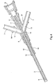
- Figure 3 is a perspective representation of the take-off needle 1 after removal of the gripping flanges 9 and the venting filter 6.
- the main hollow lance 2 is fixed in a sleeve 10 over a portion of its length.
- the venting hollow lance 5 is fixed in a support 11 also over a portion of its length.
- the back of the support 11 is open to the exterior to enable the venting hollow lance 5 to be in contact with the air, either directly, or via a venting filter 6 (see Figure 1) which can be inserted in a housing 13 provided for that purpose in the support 11.
- the holding body 8 forms a rigid structure holding the sleeve 10 and the support 11 in relation to each other such that the venting hollow lance 5 is inserted in the main hollow lance 2, the two hollow lances 2, 5 being coaxial.
- the holding body 8 defines in addition two pipes 12 forming a Y with the main hollow lance 2 to enable the flow in the hollow lance 2 to be divided into two separate and equal flows.
- the needle 1 further comprises, on each spigot 7, a collar 14 acting as an abutment for the tubes which are adapted to be connected to the spigots 7.
- a first step consists of providing a main hollow lance 2 with a sleeve 10 to obtain the assembly represented in Figure 5.
- the hollow lance 2 is formed from a tube of stainless steel comprising an end adapted to form the proximal end of the hollow lance 2 (this is the end represented in Figure 5).
- the sleeve 10 is molded onto this end in a mold of appropriate form in order for the sleeve 10 to have a cylindrical general form on which two flats 15, 16 of different length are formed (see Figure 4), as well as three collars 17.
- a core of appropriate form enables there to be formed in addition an internal channel 18 in the sleeve 10 of cylindrical form extending in line with the hollow lance 2 and comprising, at the proximal end of the sleeve 10, two crescent-shaped surfaces 19 inclined towards the interior of the internal channel 18 and towards the distal end of the sleeve 10.
- This core enabling the internal channel 18 and the surfaces 19 to be formed, is in the shape of a Y obtained by the joining together of three cylinders corresponding to the negative forms of the inner channel 18 and of the two pipes 12 (see Figure 4).
- a second step consists of molding another sleeve, referred to here as support 11, onto a tube of stainless steel of diameter less than that forming the main hollow lance 2, this tube being adapted to form the venting hollow lance 5.
- the support 11 is molded onto the venting hollow lance 5 by virtue of a mold of appropriate form to give it the external form visible in Figure 6, while an appropriate core enables the venting filter housing 13 (see Figure 4) to be formed within the support 11.
- Support 11 is such that the venting hollow lance 5 opens into the venting filter housing 13.
- venting hollow lance 5 provided with its support 11 is then inserted into the main hollow lance 2, from the end with sleeve 10 in order to slide the venting hollow lance 5 inside the main hollow lance 2 (see Figure 7).
- the hollow lances 2, 5 are disposed in a mold in which an operation will be performed of molding on the holding body 8.
- This mold (not shown) enables the precise positioning of the sleeve 10 with respect to the support 11 in the respective positions that these parts must occupy with respect to each other in the finished needle (see Figure 4).
- the flats 15, 16 of the sleeve furthermore enables angular orientation of sleeve 10 about its longitudinal axis so as to locate the crescent-shaped surfaces 10 in a predetermined position.
- Figure 7 shows the result of the operation consisting of enclosing two cylindrical core pins 20 on the back of the sleeve.
- the two core pins 20 are beveled at their end so as to form a V when these two beveled ends are enclosed onto the venting hollow lance 5.
- each core pin 20 furthermore comprises a duct enabling a passage 21 to be formed for the venting hollow lance 5 when the two core pins 20 are closed (see Figure 8).
- Figure 9 is a longitudinal cross-section of the assembly of Figure 7 and shows in detail the cooperation of the core pins 20 once enclosed with the venting hollow lance 5 and the sleeve 10.
- the V formed by the core pins 20 reproduces the form of the core which enabled the crescent-shaped surfaces 19 to be produced.
- the sleeve 10 is made from polymer material and the core pins 20 are of metal such that the metal/polymer contact is fluid-tight.
- the molding on of the holding body 8 is next performed in the mold which is adapted to form, around sleeve 10, support 11 and core pins 20, a holding body 8 of polymer in accordance with the external form in Figures 3 and 11.
- the core pins 20 are then withdrawn along their longitudinal axis after having formed the internal cylindrical surfaces of the holding body 8 which define the pipes 12.
- Figure 12 which is a longitudinal cross-section of the needle of Figure 11, shows a plan view of the arrangement of the sleeve 10 and the support 11 as was set by the holding body 8 being molded on, the latter in addition defining the pipes 12.
- Figure 12 shows the crescent-shaped surfaces 10 in a position extending in line with the pipes 12.
- FIGS 13 and 14 show the internal form of the holding body 8 obtained further to the operations described earlier.
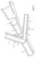
- FIG. 13 The cross-section of Figure 13 in a horizontal plane shows the communication between the pipes 12, a housing 22 receiving the sleeve 10, a connecting channel 23 adapted to receive the venting hollow lance 5, and a housing 24 for the support 11.
- the housings 22, 24 and the connecting channel 23 are formed for fluid-tight reception of the respective member with which they are adapted to cooperate.
- Figure 14 shows the same members 22, 23, 24 when a cross-section is taken of the holding body 8 in a vertical plane.
- the sharpened distal tip of the main hollow lance 2 that is to say the end which is adapted to perform a pricking operation, may be produced with a crushed heel 25 making it possible to limit the diameter of the opening of the beveled point of the main hollow lance 2.
- This provision makes it possible to avoid “coring”, that is to say that it makes it possible to avoid cutting out a cylinder from the bung 3 of the bottle 4, at the time of piercing, that rubber cylinder potentially blocking the main hollow lance 2.
- the crushed heel 25 may advantageously be produced at the time of the operation of molding on the holding body 8 by situating a punch in the mold providing that molding-on operation.
- the punch may be actuated to strike the main hollow lance 2 when the latter is placed in the mold.
Landscapes
- Health & Medical Sciences (AREA)
- Animal Behavior & Ethology (AREA)
- Public Health (AREA)
- Anesthesiology (AREA)
- Biomedical Technology (AREA)
- Heart & Thoracic Surgery (AREA)
- Hematology (AREA)
- Life Sciences & Earth Sciences (AREA)
- Vascular Medicine (AREA)
- Engineering & Computer Science (AREA)
- Veterinary Medicine (AREA)
- General Health & Medical Sciences (AREA)
- Infusion, Injection, And Reservoir Apparatuses (AREA)
- Measurement Of The Respiration, Hearing Ability, Form, And Blood Characteristics Of Living Organisms (AREA)
- Sampling And Sample Adjustment (AREA)
- External Artificial Organs (AREA)
- Apparatus Associated With Microorganisms And Enzymes (AREA)
- Measuring Or Testing Involving Enzymes Or Micro-Organisms (AREA)
Abstract
Description
- The invention concerns the general field of take-off needles adapted to be pricked through an elastic wall in order to take off liquid contained in a container closed by the wall.
- The invention more particularly concerns such a take-off needle which comprises a hollow lance generally formed from a fine steel tube provided at its distal end with a sharp pricking tip. This hollow lance is furthermore connected by its proximal end to two pipes each provided with a spigot for it to be connected to a tube.
- The pricking tip is adapted to pass through said elastic wall to enable the liquid to flow in the hollow lance towards the two pipes and tubes connected to the spigots, to take off liquid in two containers.
- The flow of the liquid in the lance towards the two pipes is thus divided into two such that half the liquid taken off is collected by each of the containers via a pipe.
- Such needles are for example used to take off liquid from a bottle closed by a rubber bung. The two spigots are then each connected in advance to a tube leading to a container. Next the needle is pricked into the bung such that its distal end passes through the bung and reaches the medium to be taken-off.
- The liquid to be taken off then flows to the two containers, each of the containers thus receiving half of the liquid taken-off, for example by gravity or with the help of a peristaltic pump or else by the pressurization of the bottle containing the liquid.
- The hollow lance and the two pipes are generally arranged in a Y to efficaciously divide the flow from the hollow lance to the pipes. These needles are referred to as "double needles".
- These double needles may be vented, that is to say that they comprise a second hollow lance, of smaller diameter than the main hollow lance, which is inserted in the main hollow lance. This second hollow lance allows the progressive introduction of air into the bottle containing the liquid to take off as the liquid flows in the main hollow lance. Such a vented needle makes it possible to carry out take-off operations from a fluid-tight bottle.
- Such double needles are known which comprise a hollow lance of which the proximal end is held in a polymer body defining an internal channel which extends from the proximal end of the hollow lance and which divides into two to form the two pipes leading to the two spigots.
- The division of the flow coming from the hollow lance is thus performed within the polymer body. The efficacy of this division may be measured by the difference in the volumes collected at the outlet of the two spigots, the volumes ideally being equal. The efficacy of the division here depends on the hydrodynamic quality of the pipes inside the polymer body, and in particular the capability of the pipes to divide the flow without creating disturbance in the flow.
- The object of the invention is to improve this type of double needle.
- To that end, the invention is directed to a take-off needle comprising a main hollow lance having a distal end adapted to perform a pricking operation, said hollow lance being connected to two pipes each provided with a spigot for it to be connected to a tube, said needle being characterized in that it comprises a body for holding the main hollow lance, said holding body defining two internal cylindrical surfaces forming said pipes, and in that the main hollow lance is fixed, by its proximal end, to a sleeve having an internal channel of which the distal end is connected to the proximal end of the main hollow lance, and of which the proximal end opens into the holding body, said sleeve comprising at its proximal end two crescent-shaped surfaces inclined towards the interior of the internal channel and towards the distal end of the sleeve, each of said crescent-shaped surfaces being disposed so as to extend in line with one of the internal cylindrical surfaces of the holding body.
- The internal geometry of such a needle ensures an equal distribution of the flow to each of the two pipes.
- The liquid to take off is led directly from the proximal end of the hollow lance to the two pipes, without dead space, that is to say without a zone in which the product could stagnate.
- A laminar flow of liquid can thus be established between the hollow lance and the two pipes.
- The extension of the cylindrical surfaces of the pipes into the sleeve of the hollow lance enables the presence of imperfections in the path of the liquid to be avoided. The flow of the liquid is consequently not disturbed in that flows along a pipe free of imperfections. Since the forms of the pipes and of the sleeve are complementary, the use of glue or any other surface preparation is furthermore avoided.
- Such a needle can consequently be mass produced at low cost.
- According to a preferred feature, the sleeve extends beyond the proximal end of the main hollow lance, the crescent-shaped surfaces being disposed away from the proximal end of the main hollow lance.
- The sleeve may furthermore be fixed to the holding body for improved rigidity of the needle.
- According to an advantageous embodiment, the sleeve is molded onto the main hollow lance. The sleeve may also comprise angular fool-proof devices which serve, for example, for positioning it in a mold.
- According to an embodiment, the needle further comprises a venting hollow lance inserted in the main hollow lance, the venting hollow lance passing through the internal channel of the sleeve, so as to form a vented needle.
- As for the main hollow lance, the venting hollow lance may comprise a support at its proximal end, the support being fixed to the holding body for improved rigidity of the needle. The support may also be molded onto the proximal end of the venting hollow lance.
- Furthermore, the holding body may be molded onto the sleeve and onto the support, so rigidly ensuring their positioning.
- According to a preferred feature, the holding body comprises a housing in which the sleeve is held; two pipes communicating with said housing; a housing for the support; said housings being aligned. The holding body may further comprise a connecting channel receiving the venting hollow lance and communicating with the two pipes.
- For a good connection of the two internal pipes of the holding body with the crescent-shaped surfaces, the sleeve may be elastically deformable.
- According to other advantageous features, the main hollow lance comprises a crushed heel at its distal end; the needle further comprises grasping means attached to the holding body.
- The invention also relates to a method of manufacturing a take-off needle as described earlier, said method comprising the following steps:
- molding the sleeve onto the main hollow lance using a V-shaped core adapted to form the crescent-shaped surfaces on the sleeve;
- molding the holding body onto the sleeve using two cylindrical core pins forming a V of the same form as said core.
- This method makes it possible to produce a take-off needle having the advantages cited above, in particular of avoiding the formation of imperfections in the junction zone extending between the proximal end of the main hollow lance and the two pipes, so as not to disturb the flow of the taken-off liquid.
- Other features and advantages of the invention appear in the light of the following description of a preferred embodiment, given by way of non-limiting example, and made with reference to the accompanying drawings in which:
- Figure 1 is a perspective view of a needle according to the invention positioned for taking off liquid contained in a sealed bottle;
- Figure 2 is a partial view in cross-section showing the cooperation of the take-off needle and the bung of the bottle of the arrangement of Figure 1;
- Figure 3 is a perspective view of the take-off needle of Figure 1 which is shown with its accessories removed;
- Figure 4 is a longitudinal cross-section of the take-off needle represented in Figure 3;
- Figure 5 shows the main hollow lance, provided with its sleeve, which is used in the take-off needle of Figures 1 to 4;
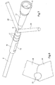
- Figure 6 is a perspective view of the venting hollow lance, provided with its support, which is used in the take-off needle of Figures 1 to 4;
- Figure 7 is a perspective view of the hollow lances of Figures 5 and 6 arranged in cooperation with the pins in a V, this assembly enabling a holding body to be molded on to form the take-off needle of Figure 3;
- Figure 8 is an enlarged view of the point of the V formed by the pins shown in Figure 7;
- Figure 9 is a longitudinal cross-section of the assembly of Figure 7;
- Figure 10 is a detail view of the cooperation between the pins in a V and the sleeve of the main hollow lance;
- Figure 11 shows the product obtained after the holding body is molded onto the assembly of Figure 7, that is to say the take-off needle of Figure 3;
- Figure 12 is a longitudinal cross-section of the take-off needle as presented in Figure 11;
- Figure 13 is a perspective view in longitudinal cross-section of the holding body alone as molded onto the assembly of Figure 7;
- Figure 14 is a perspective view in longitudinal cross-section of the holding body of Figure 13, this longitudinal cross-section being made here along a plane perpendicular to the plane of the longitudinal cross-section of Figure 13; and
- Figures 15 and 16 are views of the pricking tip of the main hollow lance, respectively in lateral cross-section, and from the front.
- Figure 1 shows a common situation of use of a take-
off needle 1 according to the invention. The mainhollow lance 2 of theneedle 1 is pricked onto therubber bung 3 of a bottle 4 connecting a liquid to be taken off. - Figure 2 is a view in cross-section showing the
bung 3 with the mainhollow lance 2 passing through it. Theneedle 1 is a vented needle in that it comprises a ventinghollow lance 5 disposed coaxially relative to and within the mainhollow lance 2. The arrows that can be seen in Figure 2, within the bottle 4, show the path along the mainhollow lance 2 of the liquid taken off while air bubbles come out of the ventinghollow lance 5 inside the bottle 4 progressively as the liquid contained in the bottle 4 is taken off. - The
venting filter 6 which can be seen in Figure 1, behind theneedle 1, is connected to the ventinghollow lance 5 and allows sterile air to be introduce into the bottle 4. - The
needle 1 comprises twospigots 7 projecting laterally from a holdingbody 8. Thesespigots 7 are connected to two internal pipes of the holdingbody 8 which are connected to the mainhollow lance 2. Thespigots 7 must consequently each be connected to a take-off tube (not shown) which thus enables the taken-off liquid to be collected. - The flow of taken-off liquid flowing in the main
hollow lance 2 is thus divided into two equal flows each directed to one of thespigots 7, which enables two equal volumes of taken off liquid to be obtained by a single take-off operation. - The
needle 1 furthermore comprises twogripping flanges 9 adapted for its manual manipulation by the user. - Figure 3 is a perspective representation of the take-off
needle 1 after removal of thegripping flanges 9 and the ventingfilter 6. - The cross-section of Figure 4 shows the internal constitution of the
needle 1. - The main
hollow lance 2 is fixed in asleeve 10 over a portion of its length. In the same way, the ventinghollow lance 5 is fixed in asupport 11 also over a portion of its length. - The back of the
support 11 is open to the exterior to enable the ventinghollow lance 5 to be in contact with the air, either directly, or via a venting filter 6 (see Figure 1) which can be inserted in ahousing 13 provided for that purpose in thesupport 11. - The holding
body 8 forms a rigid structure holding thesleeve 10 and thesupport 11 in relation to each other such that the ventinghollow lance 5 is inserted in the mainhollow lance 2, the twohollow lances - The holding
body 8 defines in addition twopipes 12 forming a Y with the mainhollow lance 2 to enable the flow in thehollow lance 2 to be divided into two separate and equal flows. - The
needle 1 further comprises, on eachspigot 7, acollar 14 acting as an abutment for the tubes which are adapted to be connected to thespigots 7. - The method of manufacturing the take-off
needle 1 of the present example will now be described with reference to Figures 5 to 12. - A first step consists of providing a main
hollow lance 2 with asleeve 10 to obtain the assembly represented in Figure 5. - The
hollow lance 2 is formed from a tube of stainless steel comprising an end adapted to form the proximal end of the hollow lance 2 (this is the end represented in Figure 5). Thesleeve 10 is molded onto this end in a mold of appropriate form in order for thesleeve 10 to have a cylindrical general form on which twoflats collars 17. - On molding the
sleeve 10 onto the mainhollow lance 2, a core of appropriate form enables there to be formed in addition aninternal channel 18 in thesleeve 10 of cylindrical form extending in line with thehollow lance 2 and comprising, at the proximal end of thesleeve 10, two crescent-shapedsurfaces 19 inclined towards the interior of theinternal channel 18 and towards the distal end of thesleeve 10. This core, enabling theinternal channel 18 and thesurfaces 19 to be formed, is in the shape of a Y obtained by the joining together of three cylinders corresponding to the negative forms of theinner channel 18 and of the two pipes 12 (see Figure 4). - With reference to Figure 6, a second step consists of molding another sleeve, referred to here as
support 11, onto a tube of stainless steel of diameter less than that forming the mainhollow lance 2, this tube being adapted to form the ventinghollow lance 5. - In the same way, the
support 11 is molded onto the ventinghollow lance 5 by virtue of a mold of appropriate form to give it the external form visible in Figure 6, while an appropriate core enables the venting filter housing 13 (see Figure 4) to be formed within thesupport 11. -
Support 11 is such that the ventinghollow lance 5 opens into the ventingfilter housing 13. - The venting
hollow lance 5 provided with itssupport 11 is then inserted into the mainhollow lance 2, from the end withsleeve 10 in order to slide the ventinghollow lance 5 inside the main hollow lance 2 (see Figure 7). - With reference to Figures 7 to 10, the
hollow lances body 8. - This mold (not shown) enables the precise positioning of the
sleeve 10 with respect to thesupport 11 in the respective positions that these parts must occupy with respect to each other in the finished needle (see Figure 4). Theflats sleeve 10 about its longitudinal axis so as to locate the crescent-shapedsurfaces 10 in a predetermined position. - Figure 7 shows the result of the operation consisting of enclosing two cylindrical core pins 20 on the back of the sleeve. The two core pins 20 are beveled at their end so as to form a V when these two beveled ends are enclosed onto the venting
hollow lance 5. - The beveled end of each
core pin 20 furthermore comprises a duct enabling apassage 21 to be formed for the ventinghollow lance 5 when the two core pins 20 are closed (see Figure 8). - Figure 9 is a longitudinal cross-section of the assembly of Figure 7 and shows in detail the cooperation of the core pins 20 once enclosed with the venting
hollow lance 5 and thesleeve 10. - The V formed by the core pins 20 reproduces the form of the core which enabled the crescent-shaped
surfaces 19 to be produced. - The core pins 20, when in the position of Figures 7 and 9, thus perfectly mates with the shape of the
sleeve 10 at the crescent-shaped surfaces 19 (see Figure 10, which is a detail view of Figure 9, the ventinghollow lance 5 not being shown in this Figure for greater clarity). - Preferably the
sleeve 10 is made from polymer material and the core pins 20 are of metal such that the metal/polymer contact is fluid-tight. - The molding on of the holding
body 8 is next performed in the mold which is adapted to form, aroundsleeve 10,support 11 and core pins 20, a holdingbody 8 of polymer in accordance with the external form in Figures 3 and 11. - The core pins 20 are then withdrawn along their longitudinal axis after having formed the internal cylindrical surfaces of the holding
body 8 which define thepipes 12. - Figure 12, which is a longitudinal cross-section of the needle of Figure 11, shows a plan view of the arrangement of the
sleeve 10 and thesupport 11 as was set by the holdingbody 8 being molded on, the latter in addition defining thepipes 12. - This method consequently leads to the production of internal cylindrical surfaces (the pipes 12) extending partially into sleeve 10 (the crescent-shaped surfaces 19).
- The view of Figure 12 shows the crescent-shaped
surfaces 10 in a position extending in line with thepipes 12. - Figures 13 and 14 show the internal form of the holding
body 8 obtained further to the operations described earlier. - The cross-section of Figure 13 in a horizontal plane shows the communication between the
pipes 12, ahousing 22 receiving thesleeve 10, a connectingchannel 23 adapted to receive the ventinghollow lance 5, and ahousing 24 for thesupport 11. - The
housings channel 23 are formed for fluid-tight reception of the respective member with which they are adapted to cooperate. - Figure 14 shows the
same members body 8 in a vertical plane. - Furthermore, with reference to Figures 15 and 16, the sharpened distal tip of the main
hollow lance 2, that is to say the end which is adapted to perform a pricking operation, may be produced with a crushedheel 25 making it possible to limit the diameter of the opening of the beveled point of the mainhollow lance 2. This provision makes it possible to avoid "coring", that is to say that it makes it possible to avoid cutting out a cylinder from thebung 3 of the bottle 4, at the time of piercing, that rubber cylinder potentially blocking the mainhollow lance 2. - The crushed
heel 25 may advantageously be produced at the time of the operation of molding on the holdingbody 8 by situating a punch in the mold providing that molding-on operation. The punch may be actuated to strike the mainhollow lance 2 when the latter is placed in the mold. - Variant embodiments of the take-off needle described and of its method of manufacture may be envisaged without departing from the scope of the invention. In particular, methods of plastic deformation may be implemented to form the crescent-shaped
surfaces 19.
Claims (15)
- A take-off needle (1) comprising a main hollow lance (2) having a distal end adapted to perform a pricking operation, said hollow lance (2) being connected to two pipes (12) each provided with a spigot (7) for it to be connected to a tube, said needle (1) being characterized in that it comprises a body (8) for holding the main hollow lance (2), said holding body (8) defining two internal cylindrical surfaces forming said pipes (12), and in that the main hollow lance (2) is fixed, by its proximal end, to a sleeve (10) having an internal channel (18) of which the distal end is connected to the proximal end of the main hollow lance (2), and of which the proximal end opens into the holding body (8), said sleeve (10) comprising at its proximal end two crescent-shaped surfaces (19) inclined towards the interior of the internal channel (18) and towards the distal end of the sleeve (10), each of said crescent-shaped surfaces (19) being disposed so as to extend in line with one of the internal cylindrical surfaces (12) of the holding body (8).
- A take-off needle according to claim 1, characterized in that the sleeve (10) extends beyond the proximal end of the main hollow lance (2), the crescent-shaped surfaces (19) being disposed away from the proximal end of the main hollow lance (2).
- A take-off needle according to one of claims 1 and 2, characterized in that the sleeve (10) is fixed to the holding body (8).
- A take-off needle according to one of claims 1 to 3, characterized in that the sleeve (10) is molded onto the main hollow lance (2).
- A take-off needle according to one of claims 1 to 4, characterized in that the sleeve (10) comprises angular fool-proof devices (15, 16).
- A take-off needle according to one of claims 1 to 5, characterized in that it further comprises a venting hollow lance (5) inserted in the main hollow lance (2), the venting hollow lance (5) passing through the internal channel (18) of the sleeve (10).
- A take-off needle according to claim 6, characterized in that the venting hollow lance (5) comprises a support (11) at its proximal end, the support (11) being fixed to the holding body (8).
- A take-off needle according to claim 7, characterized in that the support (11) is molded onto the proximal end of the venting hollow lance (5).
- A take-off needle according to one of claims 7 and 8, characterized in that the holding body (8) is molded onto the sleeve (10) and onto the support (11).
- A take-off needle according to one of claims 7 to 9, characterized in that the holding body (8) comprises a housing (22) in which the sleeve (8) is held; two pipes (12) communicating with said housing (22); a housing (24) for the support (11); said housings (22, 24) being aligned.
- A take-off needle according to claim 10, characterized in that the holding body (8) further comprises a connecting channel (23) receiving the venting hollow lance (5) and communicating with the two pipes (12).
- A take-off needle according to one of claims 1 to 11, characterized in that the sleeve (10) is elastically deformable.
- A take-off needle according to one of claims 1 to 12, characterized in that the main hollow lance (2) comprises a crushed heel (25) at its distal end.
- A take-off needle according to one of claims 1 to 13, characterized in that it further comprises grasping means (9) attached to the holding body (8).
- A method of manufacturing a take-off needle (1) in accordance with one of claims 1 to 14, the method comprising the following steps:- molding the sleeve (10) onto the main hollow lance (2) using a V-shaped core adapted to form the crescent-shaped surfaces (19) on the sleeve (10);- molding the holding body (8) onto the sleeve (10) using two cylindrical core pins (20) forming a V of the same form as said core.
Applications Claiming Priority (1)
| Application Number | Priority Date | Filing Date | Title |
|---|---|---|---|
| FR0411415A FR2876923B1 (en) | 2004-10-26 | 2004-10-26 | DUAL SAMPLE NEEDLE AND METHOD FOR PRODUCING THE SAME |
Publications (2)
| Publication Number | Publication Date |
|---|---|
| EP1652544A1 true EP1652544A1 (en) | 2006-05-03 |
| EP1652544B1 EP1652544B1 (en) | 2007-09-12 |
Family
ID=34950192
Family Applications (1)
| Application Number | Title | Priority Date | Filing Date |
|---|---|---|---|
| EP05292113A Expired - Lifetime EP1652544B1 (en) | 2004-10-26 | 2005-10-11 | Double take-off needle and method for producing it |
Country Status (8)
| Country | Link |
|---|---|
| US (1) | US7645270B2 (en) |
| EP (1) | EP1652544B1 (en) |
| JP (1) | JP4276652B2 (en) |
| CN (1) | CN100435867C (en) |
| AT (1) | ATE372796T1 (en) |
| DE (1) | DE602005002438T2 (en) |
| ES (1) | ES2293504T3 (en) |
| FR (1) | FR2876923B1 (en) |
Cited By (3)
| Publication number | Priority date | Publication date | Assignee | Title |
|---|---|---|---|---|
| WO2008067513A1 (en) * | 2006-11-30 | 2008-06-05 | Medi-Physics, Inc. | Dual-lumen needle |
| DE102007061346A1 (en) | 2007-12-17 | 2009-06-18 | Bayer Schering Pharma Aktiengesellschaft | Spike with two thorns |
| ITMO20090027A1 (en) * | 2009-02-06 | 2010-08-07 | Aries S R L | PERFORATOR DEVICE, PARTICULARLY FOR CONTAINERS OF PHYSIOLOGICAL FLUIDS FOR MEDICAL AND SIMILAR USE, AS CONTAINMENT BAGS, BOTTLES AND THE LIKE. |
Families Citing this family (11)
| Publication number | Priority date | Publication date | Assignee | Title |
|---|---|---|---|---|
| FR2876919B1 (en) * | 2004-10-26 | 2007-07-27 | Millipore Corp | HOLDING NEEDLE HAVING GAME OF GRIPPING. |
| FR2876923B1 (en) * | 2004-10-26 | 2007-03-30 | Millipore Corp | DUAL SAMPLE NEEDLE AND METHOD FOR PRODUCING THE SAME |
| JP3890066B2 (en) * | 2005-06-27 | 2007-03-07 | 積水化学工業株式会社 | Blood separation instrument and blood separation device |
| WO2007143426A2 (en) | 2006-05-30 | 2007-12-13 | Advanced Scientifics, Inc. | Device and method for accessing fluid in container |
| US8870832B2 (en) * | 2007-11-08 | 2014-10-28 | Elcam Medical A.C.A.L Ltd | Vial adaptor and manufacturing method therefor |
| JP6221206B2 (en) * | 2012-04-25 | 2017-11-01 | 株式会社島津製作所 | Liquid filling device and method for filling liquid into capillary using the liquid filling device |
| KR101864650B1 (en) * | 2016-06-03 | 2018-06-08 | (주) 유로사이언스 | Sampling dual needle syringe |
| CN109806029B (en) * | 2017-11-21 | 2021-02-09 | 杭州德晋医疗科技有限公司 | Artificial chordae tendineae implanting system with negative pressure device |
| CN109833117B (en) * | 2017-11-28 | 2020-12-25 | 杭州德晋医疗科技有限公司 | Bilateral artificial chordae tendineae implantation system |
| JP7441232B2 (en) * | 2018-10-01 | 2024-02-29 | ソシエテ・デ・プロデュイ・ネスレ・エス・アー | Enteral feeding adapter and how to use the enteral feeding adapter |
| US12023466B2 (en) * | 2020-11-10 | 2024-07-02 | Damea Alexander | Systems and methods for improving fluid flow during medication delivery procedures |
Citations (5)
| Publication number | Priority date | Publication date | Assignee | Title |
|---|---|---|---|---|
| US4292405A (en) * | 1978-03-13 | 1981-09-29 | Baxter Travenol Laboratories, Inc. | Sterility test set |
| US4351900A (en) * | 1981-01-30 | 1982-09-28 | Millipore Corporation | Test method and apparatus for the presence of microorganisms in ampoule |
| DE4122476A1 (en) * | 1991-07-06 | 1993-01-07 | Leopold Pharma Gmbh | Sterile liq. transfer in e.g. medical infusion mixts. - using double, self sealing, spined cannula coupling |
| US5407807A (en) * | 1993-04-23 | 1995-04-18 | Daymark Medical Industries, Inc. | Method and apparatus for detecting sepsis causation in a catheter |
| DE19905644A1 (en) * | 1999-02-11 | 2000-08-17 | Sartorius Gmbh | Unit for sterile extraction of a liquid from a container comprises a flame-sterilizable double cannula consisting metal outer and inner cannulas respectively for transport and exchange of the liquid against air |
Family Cites Families (13)
| Publication number | Priority date | Publication date | Assignee | Title |
|---|---|---|---|---|
| US4411661A (en) * | 1980-10-22 | 1983-10-25 | Travenol European Research And Development Centre | Spike connector |
| US5030205A (en) * | 1989-12-18 | 1991-07-09 | Critikon, Inc. | Catheter assemblies for prevention of blood leakage |
| AT398699B (en) * | 1990-07-30 | 1995-01-25 | Avl Verbrennungskraft Messtech | DIALYSIS PROBE |
| FR2671283B1 (en) * | 1991-01-08 | 1995-05-12 | Alain Durand | INTRAVASCULAR MULTI-LIGHT CATHETER, LIKELY TO BE IMPLANTED WITH TUNNELLING. |
| US5879499A (en) * | 1996-06-17 | 1999-03-09 | Heartport, Inc. | Method of manufacture of a multi-lumen catheter |
| US5762629A (en) * | 1991-10-30 | 1998-06-09 | Smith & Nephew, Inc. | Oval cannula assembly and method of use |
| US6059771A (en) * | 1996-12-23 | 2000-05-09 | Johnson & Johnson Medical, Inc. | Stiffening member to increase fluid flow within a medical device |
| US6554809B2 (en) * | 2001-08-02 | 2003-04-29 | Teodulo Aves | Epidural catheter needle |
| US6921378B2 (en) * | 2001-10-09 | 2005-07-26 | Boston Scientific Scimed, Inc. | Anti-reflux drainage devices and methods |
| US6740277B2 (en) * | 2002-04-24 | 2004-05-25 | Becton Dickinson And Company | Process of making a catheter |
| EP1511528A4 (en) * | 2002-05-16 | 2008-07-02 | Scott Lab Inc | Drug container entry mechanisms and method |
| US20050033267A1 (en) * | 2003-08-06 | 2005-02-10 | Kimberly-Clark Worldwide, Inc. | Connector with connection mechanism adapted for releasable interconnection with tube |
| FR2876923B1 (en) * | 2004-10-26 | 2007-03-30 | Millipore Corp | DUAL SAMPLE NEEDLE AND METHOD FOR PRODUCING THE SAME |
-
2004
- 2004-10-26 FR FR0411415A patent/FR2876923B1/en not_active Expired - Fee Related
-
2005
- 2005-10-11 EP EP05292113A patent/EP1652544B1/en not_active Expired - Lifetime
- 2005-10-11 US US11/247,523 patent/US7645270B2/en active Active
- 2005-10-11 DE DE602005002438T patent/DE602005002438T2/en not_active Expired - Lifetime
- 2005-10-11 ES ES05292113T patent/ES2293504T3/en not_active Expired - Lifetime
- 2005-10-11 AT AT05292113T patent/ATE372796T1/en not_active IP Right Cessation
- 2005-10-20 JP JP2005305280A patent/JP4276652B2/en not_active Expired - Lifetime
- 2005-10-24 CN CNB2005101181448A patent/CN100435867C/en not_active Expired - Lifetime
Patent Citations (5)
| Publication number | Priority date | Publication date | Assignee | Title |
|---|---|---|---|---|
| US4292405A (en) * | 1978-03-13 | 1981-09-29 | Baxter Travenol Laboratories, Inc. | Sterility test set |
| US4351900A (en) * | 1981-01-30 | 1982-09-28 | Millipore Corporation | Test method and apparatus for the presence of microorganisms in ampoule |
| DE4122476A1 (en) * | 1991-07-06 | 1993-01-07 | Leopold Pharma Gmbh | Sterile liq. transfer in e.g. medical infusion mixts. - using double, self sealing, spined cannula coupling |
| US5407807A (en) * | 1993-04-23 | 1995-04-18 | Daymark Medical Industries, Inc. | Method and apparatus for detecting sepsis causation in a catheter |
| DE19905644A1 (en) * | 1999-02-11 | 2000-08-17 | Sartorius Gmbh | Unit for sterile extraction of a liquid from a container comprises a flame-sterilizable double cannula consisting metal outer and inner cannulas respectively for transport and exchange of the liquid against air |
Cited By (3)
| Publication number | Priority date | Publication date | Assignee | Title |
|---|---|---|---|---|
| WO2008067513A1 (en) * | 2006-11-30 | 2008-06-05 | Medi-Physics, Inc. | Dual-lumen needle |
| DE102007061346A1 (en) | 2007-12-17 | 2009-06-18 | Bayer Schering Pharma Aktiengesellschaft | Spike with two thorns |
| ITMO20090027A1 (en) * | 2009-02-06 | 2010-08-07 | Aries S R L | PERFORATOR DEVICE, PARTICULARLY FOR CONTAINERS OF PHYSIOLOGICAL FLUIDS FOR MEDICAL AND SIMILAR USE, AS CONTAINMENT BAGS, BOTTLES AND THE LIKE. |
Also Published As
| Publication number | Publication date |
|---|---|
| CN1788803A (en) | 2006-06-21 |
| CN100435867C (en) | 2008-11-26 |
| JP4276652B2 (en) | 2009-06-10 |
| ATE372796T1 (en) | 2007-09-15 |
| JP2006181345A (en) | 2006-07-13 |
| US7645270B2 (en) | 2010-01-12 |
| FR2876923A1 (en) | 2006-04-28 |
| FR2876923B1 (en) | 2007-03-30 |
| DE602005002438D1 (en) | 2007-10-25 |
| ES2293504T3 (en) | 2008-03-16 |
| DE602005002438T2 (en) | 2008-06-12 |
| US20060086750A1 (en) | 2006-04-27 |
| EP1652544B1 (en) | 2007-09-12 |
Similar Documents
| Publication | Publication Date | Title |
|---|---|---|
| EP1652544B1 (en) | Double take-off needle and method for producing it | |
| US9671318B1 (en) | Specimen collector | |
| AU704610B2 (en) | Aspiration needle | |
| US5032343A (en) | Method for producing medical micro pipette tips for difficult to reach places | |
| JPS63100940A (en) | Nose member of medical micro-pipet and manufacture and usage thereof | |
| CN106943162A (en) | Biopsy device tissue sample holder with removable tray | |
| US6431015B1 (en) | Delivery apparatus with interchangeable pipette tip | |
| EP2502559A1 (en) | Inner diameter measuring device and method for priming same | |
| EP3171779B1 (en) | Segment sampler | |
| CN203988265U (en) | Scope universal trocar | |
| EP1691928B1 (en) | Bung for an aspiration assembly | |
| CN112691257A (en) | Medical injection device | |
| KR20220166293A (en) | blood extraction | |
| CN211855949U (en) | Split type U type liquid extractor | |
| CN201123940Y (en) | Cardiovascular guidewire intervented injection syringe | |
| CN214910587U (en) | Auxiliary extractor of syringe | |
| CN211561385U (en) | Puncture needle for preventing blood bag puncture | |
| CN113243939B (en) | Clinical detection device of gynaecology and obstetrics's amniotic fluid sample | |
| CN116133633B (en) | Devices, kits and methods for producing platelet-rich plasma | |
| CN201067425Y (en) | Oocyte micro-injection puncture needle | |
| CN202982165U (en) | Puncture needle tube assembly with remaining needle of needle tip protective sleeve | |
| CN215128341U (en) | Tube core with auxiliary stabilizing structure for anesthesia video laryngoscope | |
| CN111067577A (en) | A combined push-type intraosseous marrow extractor | |
| CN209404896U (en) | Veress needle | |
| EP1652543B1 (en) | A holding needle comprising gripping flanges |
Legal Events
| Date | Code | Title | Description |
|---|---|---|---|
| PUAI | Public reference made under article 153(3) epc to a published international application that has entered the european phase |
Free format text: ORIGINAL CODE: 0009012 |
|
| AK | Designated contracting states |
Kind code of ref document: A1 Designated state(s): AT BE BG CH CY CZ DE DK EE ES FI FR GB GR HU IE IS IT LI LT LU LV MC NL PL PT RO SE SI SK TR |
|
| AX | Request for extension of the european patent |
Extension state: AL BA HR MK YU |
|
| 17P | Request for examination filed |
Effective date: 20060622 |
|
| GRAP | Despatch of communication of intention to grant a patent |
Free format text: ORIGINAL CODE: EPIDOSNIGR1 |
|
| AKX | Designation fees paid |
Designated state(s): AT BE BG CH CY CZ DE DK EE ES FI FR GB GR HU IE IS IT LI LT LU LV MC NL PL PT RO SE SI SK TR |
|
| GRAS | Grant fee paid |
Free format text: ORIGINAL CODE: EPIDOSNIGR3 |
|
| GRAA | (expected) grant |
Free format text: ORIGINAL CODE: 0009210 |
|
| AK | Designated contracting states |
Kind code of ref document: B1 Designated state(s): AT BE BG CH CY CZ DE DK EE ES FI FR GB GR HU IE IS IT LI LT LU LV MC NL PL PT RO SE SI SK TR |
|
| REG | Reference to a national code |
Ref country code: GB Ref legal event code: FG4D |
|
| REG | Reference to a national code |
Ref country code: CH Ref legal event code: EP |
|
| REG | Reference to a national code |
Ref country code: CH Ref legal event code: NV Representative=s name: KIRKER & CIE S.A. |
|
| REF | Corresponds to: |
Ref document number: 602005002438 Country of ref document: DE Date of ref document: 20071025 Kind code of ref document: P |
|
| REG | Reference to a national code |
Ref country code: IE Ref legal event code: FG4D |
|
| ET | Fr: translation filed | ||
| PG25 | Lapsed in a contracting state [announced via postgrant information from national office to epo] |
Ref country code: LT Free format text: LAPSE BECAUSE OF FAILURE TO SUBMIT A TRANSLATION OF THE DESCRIPTION OR TO PAY THE FEE WITHIN THE PRESCRIBED TIME-LIMIT Effective date: 20070912 Ref country code: FI Free format text: LAPSE BECAUSE OF FAILURE TO SUBMIT A TRANSLATION OF THE DESCRIPTION OR TO PAY THE FEE WITHIN THE PRESCRIBED TIME-LIMIT Effective date: 20070912 |
|
| PG25 | Lapsed in a contracting state [announced via postgrant information from national office to epo] |
Ref country code: AT Free format text: LAPSE BECAUSE OF FAILURE TO SUBMIT A TRANSLATION OF THE DESCRIPTION OR TO PAY THE FEE WITHIN THE PRESCRIBED TIME-LIMIT Effective date: 20070912 Ref country code: PL Free format text: LAPSE BECAUSE OF FAILURE TO SUBMIT A TRANSLATION OF THE DESCRIPTION OR TO PAY THE FEE WITHIN THE PRESCRIBED TIME-LIMIT Effective date: 20070912 |
|
| REG | Reference to a national code |
Ref country code: ES Ref legal event code: FG2A Ref document number: 2293504 Country of ref document: ES Kind code of ref document: T3 |
|
| PG25 | Lapsed in a contracting state [announced via postgrant information from national office to epo] |
Ref country code: LV Free format text: LAPSE BECAUSE OF FAILURE TO SUBMIT A TRANSLATION OF THE DESCRIPTION OR TO PAY THE FEE WITHIN THE PRESCRIBED TIME-LIMIT Effective date: 20070912 |
|
| PG25 | Lapsed in a contracting state [announced via postgrant information from national office to epo] |
Ref country code: GR Free format text: LAPSE BECAUSE OF FAILURE TO SUBMIT A TRANSLATION OF THE DESCRIPTION OR TO PAY THE FEE WITHIN THE PRESCRIBED TIME-LIMIT Effective date: 20071213 |
|
| PG25 | Lapsed in a contracting state [announced via postgrant information from national office to epo] |
Ref country code: CZ Free format text: LAPSE BECAUSE OF FAILURE TO SUBMIT A TRANSLATION OF THE DESCRIPTION OR TO PAY THE FEE WITHIN THE PRESCRIBED TIME-LIMIT Effective date: 20070912 Ref country code: IS Free format text: LAPSE BECAUSE OF FAILURE TO SUBMIT A TRANSLATION OF THE DESCRIPTION OR TO PAY THE FEE WITHIN THE PRESCRIBED TIME-LIMIT Effective date: 20080112 Ref country code: MC Free format text: LAPSE BECAUSE OF NON-PAYMENT OF DUE FEES Effective date: 20071031 Ref country code: SK Free format text: LAPSE BECAUSE OF FAILURE TO SUBMIT A TRANSLATION OF THE DESCRIPTION OR TO PAY THE FEE WITHIN THE PRESCRIBED TIME-LIMIT Effective date: 20070912 Ref country code: PT Free format text: LAPSE BECAUSE OF FAILURE TO SUBMIT A TRANSLATION OF THE DESCRIPTION OR TO PAY THE FEE WITHIN THE PRESCRIBED TIME-LIMIT Effective date: 20080212 |
|
| PG25 | Lapsed in a contracting state [announced via postgrant information from national office to epo] |
Ref country code: RO Free format text: LAPSE BECAUSE OF FAILURE TO SUBMIT A TRANSLATION OF THE DESCRIPTION OR TO PAY THE FEE WITHIN THE PRESCRIBED TIME-LIMIT Effective date: 20070912 Ref country code: SE Free format text: LAPSE BECAUSE OF FAILURE TO SUBMIT A TRANSLATION OF THE DESCRIPTION OR TO PAY THE FEE WITHIN THE PRESCRIBED TIME-LIMIT Effective date: 20071212 |
|
| PLBE | No opposition filed within time limit |
Free format text: ORIGINAL CODE: 0009261 |
|
| STAA | Information on the status of an ep patent application or granted ep patent |
Free format text: STATUS: NO OPPOSITION FILED WITHIN TIME LIMIT |
|
| PG25 | Lapsed in a contracting state [announced via postgrant information from national office to epo] |
Ref country code: DK Free format text: LAPSE BECAUSE OF FAILURE TO SUBMIT A TRANSLATION OF THE DESCRIPTION OR TO PAY THE FEE WITHIN THE PRESCRIBED TIME-LIMIT Effective date: 20070912 |
|
| 26N | No opposition filed |
Effective date: 20080613 |
|
| PG25 | Lapsed in a contracting state [announced via postgrant information from national office to epo] |
Ref country code: IE Free format text: LAPSE BECAUSE OF NON-PAYMENT OF DUE FEES Effective date: 20071011 |
|
| PG25 | Lapsed in a contracting state [announced via postgrant information from national office to epo] |
Ref country code: EE Free format text: LAPSE BECAUSE OF FAILURE TO SUBMIT A TRANSLATION OF THE DESCRIPTION OR TO PAY THE FEE WITHIN THE PRESCRIBED TIME-LIMIT Effective date: 20070912 |
|
| PG25 | Lapsed in a contracting state [announced via postgrant information from national office to epo] |
Ref country code: SI Free format text: LAPSE BECAUSE OF FAILURE TO SUBMIT A TRANSLATION OF THE DESCRIPTION OR TO PAY THE FEE WITHIN THE PRESCRIBED TIME-LIMIT Effective date: 20070912 |
|
| PG25 | Lapsed in a contracting state [announced via postgrant information from national office to epo] |
Ref country code: CY Free format text: LAPSE BECAUSE OF FAILURE TO SUBMIT A TRANSLATION OF THE DESCRIPTION OR TO PAY THE FEE WITHIN THE PRESCRIBED TIME-LIMIT Effective date: 20070912 |
|
| PG25 | Lapsed in a contracting state [announced via postgrant information from national office to epo] |
Ref country code: LU Free format text: LAPSE BECAUSE OF NON-PAYMENT OF DUE FEES Effective date: 20071011 Ref country code: BG Free format text: LAPSE BECAUSE OF FAILURE TO SUBMIT A TRANSLATION OF THE DESCRIPTION OR TO PAY THE FEE WITHIN THE PRESCRIBED TIME-LIMIT Effective date: 20071212 |
|
| PG25 | Lapsed in a contracting state [announced via postgrant information from national office to epo] |
Ref country code: TR Free format text: LAPSE BECAUSE OF FAILURE TO SUBMIT A TRANSLATION OF THE DESCRIPTION OR TO PAY THE FEE WITHIN THE PRESCRIBED TIME-LIMIT Effective date: 20070912 Ref country code: HU Free format text: LAPSE BECAUSE OF FAILURE TO SUBMIT A TRANSLATION OF THE DESCRIPTION OR TO PAY THE FEE WITHIN THE PRESCRIBED TIME-LIMIT Effective date: 20080313 |
|
| PG25 | Lapsed in a contracting state [announced via postgrant information from national office to epo] |
Ref country code: IT Free format text: LAPSE BECAUSE OF NON-PAYMENT OF DUE FEES Effective date: 20071031 |
|
| REG | Reference to a national code |
Ref country code: CH Ref legal event code: PFA Owner name: EMD MILLIPORE CORPORATION Free format text: MILLIPORE CORPORATION#290 CONCORD ROAD#BILLERICA MASSACHUSETTS 01821 (US) -TRANSFER TO- EMD MILLIPORE CORPORATION#290 CONCORD ROAD#BILLERICA, MA 01821 (US) |
|
| REG | Reference to a national code |
Ref country code: NL Ref legal event code: TD Effective date: 20120227 |
|
| REG | Reference to a national code |
Ref country code: ES Ref legal event code: PC2A Owner name: EMD MILLIPORE CORPORATION Effective date: 20120416 |
|
| REG | Reference to a national code |
Ref country code: FR Ref legal event code: CD Owner name: EMD MILLIPORE CORPORATION Effective date: 20120327 |
|
| REG | Reference to a national code |
Ref country code: DE Ref legal event code: R082 Ref document number: 602005002438 Country of ref document: DE Representative=s name: HENKEL, BREUER & PARTNER, DE |
|
| REG | Reference to a national code |
Ref country code: DE Ref legal event code: R082 Ref document number: 602005002438 Country of ref document: DE Representative=s name: PATENTANWAELTE HENKEL, BREUER & PARTNER, DE Effective date: 20120613 Ref country code: DE Ref legal event code: R081 Ref document number: 602005002438 Country of ref document: DE Owner name: EMD MILLIPORE CORPORATION, BILLERICA, US Free format text: FORMER OWNER: MILLIPORE CORP., BILLERICA, MASS., US Effective date: 20120613 |
|
| REG | Reference to a national code |
Ref country code: FR Ref legal event code: PLFP Year of fee payment: 12 |
|
| REG | Reference to a national code |
Ref country code: FR Ref legal event code: PLFP Year of fee payment: 13 |
|
| REG | Reference to a national code |
Ref country code: FR Ref legal event code: PLFP Year of fee payment: 14 |
|
| P01 | Opt-out of the competence of the unified patent court (upc) registered |
Effective date: 20230602 |
|
| PGFP | Annual fee paid to national office [announced via postgrant information from national office to epo] |
Ref country code: GB Payment date: 20240905 Year of fee payment: 20 |
|
| PGFP | Annual fee paid to national office [announced via postgrant information from national office to epo] |
Ref country code: BE Payment date: 20240917 Year of fee payment: 20 |
|
| PGFP | Annual fee paid to national office [announced via postgrant information from national office to epo] |
Ref country code: FR Payment date: 20240909 Year of fee payment: 20 |
|
| PGFP | Annual fee paid to national office [announced via postgrant information from national office to epo] |
Ref country code: NL Payment date: 20240917 Year of fee payment: 20 |
|
| PGFP | Annual fee paid to national office [announced via postgrant information from national office to epo] |
Ref country code: DE Payment date: 20240904 Year of fee payment: 20 |
|
| PGFP | Annual fee paid to national office [announced via postgrant information from national office to epo] |
Ref country code: ES Payment date: 20241101 Year of fee payment: 20 |
|
| PGFP | Annual fee paid to national office [announced via postgrant information from national office to epo] |
Ref country code: CH Payment date: 20241101 Year of fee payment: 20 |
|
| REG | Reference to a national code |
Ref country code: DE Ref legal event code: R071 Ref document number: 602005002438 Country of ref document: DE Ref country code: CH Ref legal event code: H14 Free format text: ST27 STATUS EVENT CODE: U-0-0-H10-H14 (AS PROVIDED BY THE NATIONAL OFFICE) Effective date: 20251011 |
|
| REG | Reference to a national code |
Ref country code: NL Ref legal event code: MK Effective date: 20251010 |
|
| REG | Reference to a national code |
Ref country code: ES Ref legal event code: FD2A Effective date: 20251024 |
|
| REG | Reference to a national code |
Ref country code: GB Ref legal event code: PE20 Expiry date: 20251010 |
|
| REG | Reference to a national code |
Ref country code: BE Ref legal event code: MK Effective date: 20251011 |
|
| PG25 | Lapsed in a contracting state [announced via postgrant information from national office to epo] |
Ref country code: ES Free format text: LAPSE BECAUSE OF EXPIRATION OF PROTECTION Effective date: 20251012 |