EP1652497B1 - Adapter, lid and connector for ostomy bags - Google Patents
Adapter, lid and connector for ostomy bags Download PDFInfo
- Publication number
- EP1652497B1 EP1652497B1 EP04077965A EP04077965A EP1652497B1 EP 1652497 B1 EP1652497 B1 EP 1652497B1 EP 04077965 A EP04077965 A EP 04077965A EP 04077965 A EP04077965 A EP 04077965A EP 1652497 B1 EP1652497 B1 EP 1652497B1
- Authority
- EP
- European Patent Office
- Prior art keywords
- adapter
- connector
- lid
- opening
- recess
- Prior art date
- Legal status (The legal status is an assumption and is not a legal conclusion. Google has not performed a legal analysis and makes no representation as to the accuracy of the status listed.)
- Not-in-force
Links
- 238000000034 method Methods 0.000 claims description 14
- 239000007943 implant Substances 0.000 claims description 6
- 230000000295 complement effect Effects 0.000 claims description 5
- 239000002699 waste material Substances 0.000 abstract description 15
- 235000019645 odor Nutrition 0.000 abstract description 12
- 239000000853 adhesive Substances 0.000 description 12
- 230000001070 adhesive effect Effects 0.000 description 12
- 239000007789 gas Substances 0.000 description 5
- OKTJSMMVPCPJKN-UHFFFAOYSA-N Carbon Chemical compound [C] OKTJSMMVPCPJKN-UHFFFAOYSA-N 0.000 description 4
- 229910052799 carbon Inorganic materials 0.000 description 4
- 238000007373 indentation Methods 0.000 description 3
- 210000003815 abdominal wall Anatomy 0.000 description 2
- 230000008878 coupling Effects 0.000 description 2
- 238000010168 coupling process Methods 0.000 description 2
- 238000005859 coupling reaction Methods 0.000 description 2
- 210000000936 intestine Anatomy 0.000 description 2
- 239000003566 sealing material Substances 0.000 description 2
- 239000000126 substance Substances 0.000 description 2
- 210000001519 tissue Anatomy 0.000 description 2
- 206010005003 Bladder cancer Diseases 0.000 description 1
- 206010009900 Colitis ulcerative Diseases 0.000 description 1
- 208000011231 Crohn disease Diseases 0.000 description 1
- 208000005016 Intestinal Neoplasms Diseases 0.000 description 1
- 201000006704 Ulcerative Colitis Diseases 0.000 description 1
- 208000007097 Urinary Bladder Neoplasms Diseases 0.000 description 1
- 208000027418 Wounds and injury Diseases 0.000 description 1
- 239000002390 adhesive tape Substances 0.000 description 1
- 230000006378 damage Effects 0.000 description 1
- 201000010099 disease Diseases 0.000 description 1
- 208000037265 diseases, disorders, signs and symptoms Diseases 0.000 description 1
- 230000000694 effects Effects 0.000 description 1
- 210000000981 epithelium Anatomy 0.000 description 1
- 210000005224 forefinger Anatomy 0.000 description 1
- 208000014674 injury Diseases 0.000 description 1
- 201000002313 intestinal cancer Diseases 0.000 description 1
- 208000015768 polyposis Diseases 0.000 description 1
- 238000001356 surgical procedure Methods 0.000 description 1
- 210000003813 thumb Anatomy 0.000 description 1
- 201000005112 urinary bladder cancer Diseases 0.000 description 1
- 230000003245 working effect Effects 0.000 description 1
Images


Classifications
-
- A—HUMAN NECESSITIES
- A61—MEDICAL OR VETERINARY SCIENCE; HYGIENE
- A61F—FILTERS IMPLANTABLE INTO BLOOD VESSELS; PROSTHESES; DEVICES PROVIDING PATENCY TO, OR PREVENTING COLLAPSING OF, TUBULAR STRUCTURES OF THE BODY, e.g. STENTS; ORTHOPAEDIC, NURSING OR CONTRACEPTIVE DEVICES; FOMENTATION; TREATMENT OR PROTECTION OF EYES OR EARS; BANDAGES, DRESSINGS OR ABSORBENT PADS; FIRST-AID KITS
- A61F5/00—Orthopaedic methods or devices for non-surgical treatment of bones or joints; Nursing devices; Anti-rape devices
- A61F5/44—Devices worn by the patient for reception of urine, faeces, catamenial or other discharge; Portable urination aids; Colostomy devices
- A61F5/4404—Details or parts
- A61F5/4407—Closure means other than valves
-
- A—HUMAN NECESSITIES
- A61—MEDICAL OR VETERINARY SCIENCE; HYGIENE
- A61F—FILTERS IMPLANTABLE INTO BLOOD VESSELS; PROSTHESES; DEVICES PROVIDING PATENCY TO, OR PREVENTING COLLAPSING OF, TUBULAR STRUCTURES OF THE BODY, e.g. STENTS; ORTHOPAEDIC, NURSING OR CONTRACEPTIVE DEVICES; FOMENTATION; TREATMENT OR PROTECTION OF EYES OR EARS; BANDAGES, DRESSINGS OR ABSORBENT PADS; FIRST-AID KITS
- A61F5/00—Orthopaedic methods or devices for non-surgical treatment of bones or joints; Nursing devices; Anti-rape devices
- A61F5/44—Devices worn by the patient for reception of urine, faeces, catamenial or other discharge; Portable urination aids; Colostomy devices
- A61F5/445—Colostomy, ileostomy or urethrostomy devices
- A61F5/448—Means for attaching bag to seal ring
Definitions
- the invention relates to an adapter intended to be attached to a human or animal body at a stoma, a detachable lid on the adapter, and a connector for connecting an ostomy bag to the adapter.
- the adapter is of the kind which comprises a protruding section, in use, extending from the stoma, and mounting means for mounting a detachable lid onto the end of the protruding section.
- the invention also relates to a method of connecting an ostomy bag to an adapter at a stoma and a method of removing an ostomy bag from an adapter at a stoma.
- a lid exchanger for replacing the lid on the adapter with a replacement lid and a method of using the lid exchanger are also provided.
- an external bag typically called an ostomy bag
- an ostomy bag is connected to the stoma in order to collect bodily waste.
- the ostomy bag is filled, it is removed and emptied.
- Some ostomy bags can be cleaned and reused while other ostomy bags are discarded and replaced with new ones.
- the ostomy bag can be connected directly to the stoma by attaching it to the skin with an adhesive substance.
- the ostomy bag is detachably connected to an adapter mounted at the stoma.
- the adapter is usually attached to the body at the stoma with an adhesive wafer. This means that the bag can be emptied or replaced more frequently without needing to disrupt the adhesive contact at the body.
- WO 03/013404 provides a coupling for connecting an ostomy bag to an adapter having a tubular protruding section.
- the adapter could either be attached to the skin around the stoma with an adhesive or the adapter could be surgically implanted at the stoma.
- the coupling according to WO 03/013404 clamps onto the tubular protruding section of the adapter when the user presses two co-axial discs together. The user releases the bag from the adapter by pulling the two co-axial discs away from each other.
- the two co-axial discs are located on the inside surface of the ostomy bag.
- a first aspect of the current invention is to provide an adapter, a detachable lid, and a connector as mentioned in the opening paragraph in order to ensure that no waste or odors are released from the adapter and/or the ostomy bag while the ostomy bag is being exchanged or emptied.
- a second aspect of the current invention is to provide an adapter, a detachable lid and a connector as mentioned in the opening paragraph which are easy to operate.
- a third aspect of the current invention is to provide a connector as mentioned in the opening paragraph which replaces the detachable lid on the adapter when the ostomy bag is exchanged.
- a fourth aspect of the current invention is to provide a method of removing an ostomy bag from an adapter at a stoma and a method of connecting an ostomy bag to an adapter at a stoma which ensure that no waste or odors are released during the removing and the connecting respectively.
- the new and unique way in which the adapter according to the current invention fulfills the above mentioned aspects is that the mounting means are arranged such that the detachable lid is mounted onto and removed from the end of the protruding section by sliding the detachable lid in a direction relatively perpendicular to the axis of the protruding section.
- the adapter can be inserted into a connector which can slide the lid off the adapter once the bag is connected to the adapter.
- the connector can then slide the lid onto the adapter again, when the bag is to be removed from the adapter.
- This means that the only time that the adapter is open is when the ostomy bag is connected to the adapter. This ensures that there is no leakage from the adapter and that no odors are released during the exchange or the emptying of the bag.
- the mounting means can comprise grooves or ridges formed complementary to ridges or grooves respectively on the detachable lid, the grooves or ridges running perpendicular to the axis of the tubular section.
- the adapter can be an implant. This allows the adapter to become an integrated part of the body. This also allows the adapter to withstand higher forces and allows the adapter to be used with the lid on for longer periods of time.
- the traditional adapter which is attached to the body with an adhesive can not withstand much back pressure before the adhesive releases from the body.
- the invention further comprises a detachable lid as mentioned in the opening paragraph which is arranged to be mounted onto and removed from the end of a protruding section of an adapter by sliding the lid substantially perpendicularly to the axis of the protruding section. This allows it to work together with the adapter according to the invention.
- the lid can further comprise ridges or grooves which are formed complementary to grooves or ridges respectively on the adapter which run perpendicular to the axis of the protruding section of the adapter. This is a simple way to make the lid slideable with respect to the adapter.
- the detachable lid can further comprise a first seal which prevents waste and odors from escaping the adapter.
- the lid can furthermore be made gas permeable to ensure that high pressure is not built up behind the adapter.
- the lid can also comprise an odor filter.
- the invention further comprises a connector as mentioned in the opening paragraph which comprises: a first part, a second part arranged such that it is displaceable with respect to the first part, a first through going opening in the first part, arranged such that the protruding section of the adapter is insertable into the first opening, a first recess in the second part to accept the detachable lid mounted on the adapter, a second through going opening in the second part beside the recess, and sliding means to slide the second part relative to the first part, from a first position where the first recess is aligned with the first opening, to a second position where the second opening is aligned with the first opening.
- a connector is provided which can connect an ostomy bag to an adapter with a detachable lid and disconnect an ostomy bag from an adapter with a detachable lid without any waste or odor leakage.
- the connector can be integrated directly into the ostomy bag.
- the first part can be attached to the inside surface of the ostomy bag. In this way, the connector and all the waste remain inside the bag. In addition there is nothing on the outside of the bag which can snag on clothing or other objects.
- the connector can further comprise a first tab on the first part and a second and third tab on the second part, where in the first position the second tab is substantially aligned with the first tab and in the second position the third tab is substantially aligned with the first tab.
- the connector can be moved from the first position to the second position by squeezing the first tab and the third tab together.
- the connector can be moved from the second position to the first position by squeezing the first tab and the second tab together.
- the connector can further comprise a second seal around the second opening which prevents waste or odor leakage when the bag is connected to the adapter.
- the connector can furthermore be arranged such that one surface of a first seal in the detachable lid and one surface of the second seal lie on a common plane when the adapter is inserted into the connector. In this way, no waste or odor leakage occurs during connection and disconnection of the bag from the adapter.
- the connector can further comprise ridges or grooves on the second part of the connector which engage with grooves or ridges respectively on the adapter in the second position of the connector.
- the connector can further comprise first alignment means at the first recess corresponding to second alignment means at the lid of the adapter. In this way it is ensured that the adapter is inserted properly into the connector. Proper alignment ensures that it is possible for the connector to easily slide the lid off the adapter.
- the connector can further comprise a second recess in the second part beside the second opening and a replacement detachable lid arranged in the second recess, the second recess being placed on the opposite side of the second opening as the first recess.
- a lid exchanger can be used to exchange the lid.
- a lid exchanger comprises: a first part, a second part arranged such that it is displaceable with respect to the first part, a first through going opening in the first part arranged such that the protruding section of the adapter is insertable into the first opening, a first recess in the second part to accept the detachable lid, a second recess in the second part beside the first recess, a replacement detachable lid arranged in the second recess, and sliding means to slide the second part relative to the first part, from a first position where the first recess is aligned with the first opening to a second position where the second recess is aligned with the first opening.
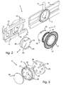
- the main components shown in figures 1 and 2 are an ostomy bag 1, a connector 2, an adapter 3, and a detachable lid 4 mounted on the adapter 3.
- the connector 2 is attached to the ostomy bag 1 on the inside of the bag.
- the connector 2 is therefore shown using dotted lines.
- the connector comprises a first part 5 and a second part 6.
- the first part 5 and the second part 6 are connected to each other with sliding means which allows the second part 6 to slide sideways with respect to the first part 5.
- the first part 5 further comprises a first through going opening 9.
- the second part 6 further comprises a first recess 10 and a second through going opening 11.
- a seal 12 with a flat surface 13 is formed around the second opening 11. The seal 12 is firmly connected to the second part thereby preventing it from shifting sideways when the second part is slid with respect to the first part.
- a first tab 14 is formed on the first part.
- a second 15 and third tab 16 are mounted on the second part. The tabs are used to slide the second part 6 sideways relative to the first part 5.
- the first tab 14 is slightly higher than the second 15 and third 16 tabs. This makes it easy for the user to distinguish between the first tab and the second and third tabs.
- the connector has two main positions. In the connector's first position, the first through going opening 9 in the first part is aligned with the first recess 10. In the connector's second position, the first opening 9 is aligned with the second through going opening 11 in the second part.
- the first tab 14 In the first position of the connector, the first tab 14 is roughly aligned with the second tab 15.
- the third tab 16 is at a distance to the left (as seen in the figure) from the first tab 14.
- the user applies pressure to the first tab 14 and the third tab 16 in order to press the two tabs together. This can be achieved by squeezing the two tabs together using the thumb and the forefinger. Since the second tab 15 and the first tab 14 are roughly aligned, the user won't be confused as to which tabs he or she should squeeze together. This is important because the connector in the current embodiment is inside the bag and the user can't see connector.
- the third tab 16 and the first tab 14 will be roughly aligned.
- pressure is applied to the first 14 and second 16 tabs. Again since the first tab 14 and the third tab 16 are roughly aligned, the user won't be confused as to which tabs he or she should apply pressure to.
- Another advantage of the tab setup is that since the user applies pressure between the two tabs, no force is transmitted to the adapter. This reduces the risk of injuries to the body around the adapter. In many current systems, the user has to force the connector off the adapter. This applies large stresses to the connection between the adapter and the body.
- the first part 5 of the connector is attached to the inside surface of the ostomy bag 1. This ensures that all the waste remains inside the bag, both while the bag is connected to the adapter and once it is removed.
- the connector is attached to the outside of the bag. In this case, the second part 6 of the connector would be connected to the outside surface of the bag.
- the adapter 3 in the current example is an implant and is surgically implanted into the body of the user at the stoma. In effect, the adapter forms the stoma.
- the adapter comprises a radial flange 17, a tubular protruding section 18, a set of circumferential ribs 19, and mounting means 20.
- the radial flange is surgically implanted into the abdominal wall.
- the holes 21 in the radial flange 17 permit tissue to grow through the flange 17, thereby ensuring a strong and robust connection between the body and the adapter.
- the circumferential ribs 19 in the protruding section of the adapter serve to promote firm mechanical securing of the protruding section to the surrounding tissue. Furthermore the ribs impede downgrowth of the epithelium. More details of the implant, as shown in the figures, can be found in the inventor's European Patent application EP 1632201 .
- Mounting means 20, for mounting a detachable lid 4 are arranged at the end of the protruding section.
- the mounting means comprises two grooves 20 in the end of the protruding section. The grooves 20 run perpendicular to the longitudinal axis of the protruding section 18. This allows the lid to be slid on and off the adapter in a direction which is perpendicular to the axis of the protruding section.
- the lid 4 shown in figures 1 , 2 and 3 has three components: a rigid plastic part 22, a seal 23, and a carbon filter 24 (can only be seen in figure 3 ).
- the rigid plastic part 22 is formed with two rails 25 which engage with the grooves 20 on the adapter when the lid is mounted on the adapter. The rails allow the lid to be slid on and off the adapter in a direction which is perpendicular to the axis of the protruding section.
- the seal 23 is made from a sealing material, such as rubber, and has three small holes 26 which go through the seal. This allows gases to pass through the lid.
- the lid also has alignment means 30 which match corresponding alignment means 31 in the first recess 10 of the second part 6 of the connector 2.
- the first alignment means 31 in the first recess comprise two raised ridges on the bottom surface of the recess.
- the second alignment means 30 on the lid comprises two flattened parts on the outer periphery of the rigid plastic part.
- the alignment means could be formed in many other ways as well.
- the alignment means in the recess could be a groove running along the bottom of the recess and the alignment means on the lid could be a ridge which corresponds to the groove in the recess.
- the adapter shown in the figures has a circular cross section. In other embodiments, the adapter could have a non-circular cross section, for example elliptical. This would ensure that the adapter and the connector are properly aligned when the adapter is inserted in the connector.
- the lid and the adapter can also have a locking arrangement which secures the lid on the adapter during normal use and prevents it from being slid off. This is not shown in the figures.
- an outer lid can be placed over the lid and adapter during normal use. Before connecting the adapter to the bag, the outer lid would be removed. After disconnecting the bag, the outer lid would be mounted again.
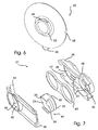
- Figures 4 and 5 show two of the steps of connecting the ostomy bag equipped with the connector to the adapter. So that the inner workings of the adapter and connector can be seen, the ostomy bag and the first part of the connector are not shown.
- Figure 4 shows the connector in its first position and figure 5 shows the connector in its second position. It should be noted that the first through going opening 9 in the first part 5 would be aligned with the protruding section 18 of the adapter 3 if the first part where shown in figures 4 and 5 .
- the adapter has just been inserted into the first through going opening in the first part.
- the lid 4 fits into the first recess 10 in the second part of the connector.
- the second part has been slid to the right (according to the figure) with respect to the adapter and the first part of the connector.
- the protruding section of the adapter and the first opening in the first part of the connector are brought inline with the second opening in the second part of the connector. In this case, waste can be expelled through the protruding section of the adapter and be collected in the ostomy bag.
- the lid While the connector is in the second position, the lid is held in the first recess. Also, while the connector is in the second position, the ridges of the second part of the connector engage with the grooves at the end of the adapter, thereby locking the adapter to the connector.
- top surface 13 of the seal 12 in the second part of the lid is aligned with the top surface of the second seal 23, thereby allowing the end of the protruding section of the adapter to slide on a common surface between the first position and the second position. In this way, it is possible to ensure that no leakage occurs while the connector is being moved from the first position to the second position.
- the user applies pressure between the second tab 15 and the first tab 14. This causes the second part to slide to the left (according to the figure) with respect to the first part of the connector and the adapter.
- the lid is slid onto the protruding section of the adapter, the second opening in the second part of the connector is closed, and the connector unlocks the adapter which allows the user to remove the adapter from the connector.
- the adapter is now closed again with the old lid.
- FIG. 6 shows a second embodiment 32 of an adapter according to the invention.
- This adapter 32 is designed to be attached to the body around a traditional stoma using adhesive tape.
- the adapter comprises a protruding section 33, mounting means 34, an adhesive wafer 35 rigidly connected to the base of the protruding section, and a peel off cover 36 on the adhesive wafer.
- the mounting means 34 on this adapter are identical to the mounting means on the adapter 3 described in figures 1 and 2 . This means that a lid identical to the one shown in figures 1-3 and described above can be attached to this adapter in the same way as was described above.
- the adhesive wafer is attached around the stoma in the same way as a traditional connector for an ostomy bag is attached to the stoma.
- an ostomy bag with a connector as shown in figures 1 and 2 can be attached to the adapter in the same way as described above. This allows people with a traditional stoma to use a bag with a connector according to the current invention, thereby eliminating the risks of leakage during the bag exchange process.
- the adapter Since the adapter is only attached to the skin via the adhesive wafer, the bond is not as strong as with an implant. Therefore, the user should not go for too long with the lid on the adapter. This could cause a pressure to be applied to the adapter which could cause the adhesive to release. It would therefore be recommended to use a bag connected to this type of adapter at all times.
- the bag can be formed with a gas permeable opening and a carbon filter in order to let gases escape from the bag.
- a lid exchanger 37 as shown in figure 7 can be used for this purpose.
- the lid exchanger 37 is very similar in principle to the connector 2 as described above.
- the lid exchanger 37 comprises a first part 38, a second part 39, a seal 40, and a replacement lid 41.
- the replacement lid is identical to the one described above and therefore won't be described further here.
- the first part 38 comprises a first opening 42, grooves 43 and a first tab 44.
- the second part 39 comprises a first recess 45, a second recess 46, ridges 47, and a second tab 48.
- the first and second parts are slideably connected together via the grooves 43 and the ridges 47.
- the replacement lid 41 is arranged inside the second recess 46.
- the lid exchanger has two main positions, a first position where the first opening is aligned with the first recess and a second position where the first opening is aligned with the second recess.
- the adapter with the old lid is inserted into first opening of the lid exchanger when it is in a first position.
- the lid is therefore inserted into the first recess.
- the user then applies pressure between the first 44 and second 48 tabs and slides the second part relative to the first part. In this way, the first lid is slid off the adapter and the replacement lid is slid onto the end of the adapter.
- the adapter can be removed from the lid exchanger.
- the old lid remains in the lid exchanger which can now be discarded and the replacement lid is mounted on the end of the adapter.
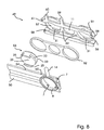
- Figure 8 shows a second embodiment 49 of a connector according to the invention.
- the connector 49 is similar to the connector 2 as described above and the same reference numerals will therefore be used to describe similar parts.
- the second embodiment 49 of the connector however, exchanges the old lid with a replacement lid after the bag has been filled.
- the connector 49 comprises a first part 50, a second part 51, a seal 52 and a replacement lid 53.
- the replacement lid 53 is identical to the lid 4 described above and it will therefore not be described further here.
- the first part 50 has a first opening 9, grooves 7, a first tab 14, and two indentations 54,55 on the top of the first part.
- the second part 51 comprises a first recess 56, a second recess 57, a second opening 11, ridges 58, a second 59 and third 60 tab, and a protrusion 61.
- the recesses have alignment means 31.
- the new lid 53 is arranged inside the second recess 57.
- the seal 52 fits into the second part 51 as was the case in the previously described connector 2.
- the seal is made from a flat sealing material. Circular protrusions (hidden in the figure) on the seal 52 engage with holes 62 in the second part in order to hold the seal in place.
- the connector 49 has three main positions. In the first position, the first opening 9 is aligned with the first recess 56. In the second position, the first opening 9 is aligned with the second opening 11. In the third position, the first opening 9 is aligned with the second recess 57.
- the user When the user desires to fill the bag, the user inserts the adapter with the old lid into the first opening. This brings the old lid into the first recess. The user then squeezes the first and second tabs together, thereby causing the second part to slide relative to the first part. The user keeps pressing until the protrusion 61 clicks into the first indentation 54 with an audible click. Waste can then be emptied from the user into the bag through the second opening. The old lid is held in the first recess.
- the user applies pressure between the first tab 14 and the third tab 60. This causes the second part 51 to slide further to the right relative to the first part 50. The user continues to apply pressure until the protrusion 61 falls into the second indentation 55 in the first part with an audible click.
- the second opening is now closed and the replacement lid is now mounted onto the adapter. The user can then remove the adapter from the connector.
- the adapter now has a new lid mounted on the end of the adapter and the old lid is held in the connector inside the bag. The bag can then be discarded.
- the two parts of the connector are linearly displaceable with respect to each other.
- the two parts are, for example, rotateably displaceable with respect to each other.
Landscapes
- Health & Medical Sciences (AREA)
- Epidemiology (AREA)
- Nursing (AREA)
- Orthopedic Medicine & Surgery (AREA)
- Engineering & Computer Science (AREA)
- Biomedical Technology (AREA)
- Heart & Thoracic Surgery (AREA)
- Vascular Medicine (AREA)
- Life Sciences & Earth Sciences (AREA)
- Animal Behavior & Ethology (AREA)
- General Health & Medical Sciences (AREA)
- Public Health (AREA)
- Veterinary Medicine (AREA)
- Orthopedics, Nursing, And Contraception (AREA)
Abstract
Description
- The invention relates to an adapter intended to be attached to a human or animal body at a stoma, a detachable lid on the adapter, and a connector for connecting an ostomy bag to the adapter. The adapter is of the kind which comprises a protruding section, in use, extending from the stoma, and mounting means for mounting a detachable lid onto the end of the protruding section.
- The document
WO-A-00/62722 - The invention also relates to a method of connecting an ostomy bag to an adapter at a stoma and a method of removing an ostomy bag from an adapter at a stoma. A lid exchanger for replacing the lid on the adapter with a replacement lid and a method of using the lid exchanger are also provided.
- The document
WO 2004/108016 , published after the filing date of the present application, discloses an adapter, wherein the lid is not detachable. - Many diseases such as e.g. Crohn's disease, ulcerative colitis, intestinal cancer and adenomatous polyposis or bladder cancer require removal of all or part of the intestines or bladder. When the intestines or the bladder are removed, the bodily wastes are expelled through a new surgical opening in the abdominal wall. The surgery to create the new opening, the stoma, is called ostomy.
- Once the stoma has been created, an external bag, typically called an ostomy bag, is connected to the stoma in order to collect bodily waste. When the ostomy bag is filled, it is removed and emptied. Some ostomy bags can be cleaned and reused while other ostomy bags are discarded and replaced with new ones.
- The ostomy bag can be connected directly to the stoma by attaching it to the skin with an adhesive substance. However, typically the ostomy bag is detachably connected to an adapter mounted at the stoma. The adapter is usually attached to the body at the stoma with an adhesive wafer. This means that the bag can be emptied or replaced more frequently without needing to disrupt the adhesive contact at the body.
- New adapters however have recently been developed which can be implanted into the body at the stoma. See for example the inventor's
EP patent application EP 1632201 . These "implants" become an integrated part of the body which creates a stronger and more robust connection between the body and the adapter. In addition, it is not necessary to use an adhesive substance to attach the adapter to the body. - There are many different types of systems which allow ostomy bags to be connected to an adapter at a stoma. One example of such a system is provided by
WO 03/013404 WO 03/013404 WO 03/013404 - However, the big disadvantage with currently available systems is that during the exchange procedure, both the adapter and the bag are open. This means that there is a risk of odors or waste leaking from the stoma and/or the bag. This makes exchanging the ostomy bag a rather unpleasant task.
- A first aspect of the current invention is to provide an adapter, a detachable lid, and a connector as mentioned in the opening paragraph in order to ensure that no waste or odors are released from the adapter and/or the ostomy bag while the ostomy bag is being exchanged or emptied.
- A second aspect of the current invention is to provide an adapter, a detachable lid and a connector as mentioned in the opening paragraph which are easy to operate.
- A third aspect of the current invention is to provide a connector as mentioned in the opening paragraph which replaces the detachable lid on the adapter when the ostomy bag is exchanged.
- A fourth aspect of the current invention is to provide a method of removing an ostomy bag from an adapter at a stoma and a method of connecting an ostomy bag to an adapter at a stoma which ensure that no waste or odors are released during the removing and the connecting respectively.
- The new and unique way in which the adapter according to the current invention fulfills the above mentioned aspects is that the mounting means are arranged such that the detachable lid is mounted onto and removed from the end of the protruding section by sliding the detachable lid in a direction relatively perpendicular to the axis of the protruding section. In this way, the adapter can be inserted into a connector which can slide the lid off the adapter once the bag is connected to the adapter. The connector can then slide the lid onto the adapter again, when the bag is to be removed from the adapter. This means that the only time that the adapter is open is when the ostomy bag is connected to the adapter. This ensures that there is no leakage from the adapter and that no odors are released during the exchange or the emptying of the bag.
- In an advantageous embodiment, the mounting means can comprise grooves or ridges formed complementary to ridges or grooves respectively on the detachable lid, the grooves or ridges running perpendicular to the axis of the tubular section. This is a simple way of allowing the detachable lid to be held in place during normal use, but easily slid off the end of the adapter when the bag is to be exchanged.
- In an especially advantageous embodiment, the adapter can be an implant. This allows the adapter to become an integrated part of the body. This also allows the adapter to withstand higher forces and allows the adapter to be used with the lid on for longer periods of time. The traditional adapter which is attached to the body with an adhesive can not withstand much back pressure before the adhesive releases from the body.
- The invention further comprises a detachable lid as mentioned in the opening paragraph which is arranged to be mounted onto and removed from the end of a protruding section of an adapter by sliding the lid substantially perpendicularly to the axis of the protruding section. This allows it to work together with the adapter according to the invention.
- In an advantageous embodiment, the lid can further comprise ridges or grooves which are formed complementary to grooves or ridges respectively on the adapter which run perpendicular to the axis of the protruding section of the adapter. This is a simple way to make the lid slideable with respect to the adapter.
- The detachable lid can further comprise a first seal which prevents waste and odors from escaping the adapter. The lid can furthermore be made gas permeable to ensure that high pressure is not built up behind the adapter. In order to remove odors from the gases passing through the lid, the lid can also comprise an odor filter.
- The invention further comprises a connector as mentioned in the opening paragraph which comprises: a first part, a second part arranged such that it is displaceable with respect to the first part, a first through going opening in the first part, arranged such that the protruding section of the adapter is insertable into the first opening, a first recess in the second part to accept the detachable lid mounted on the adapter, a second through going opening in the second part beside the recess, and sliding means to slide the second part relative to the first part, from a first position where the first recess is aligned with the first opening, to a second position where the second opening is aligned with the first opening. In this way, a connector is provided which can connect an ostomy bag to an adapter with a detachable lid and disconnect an ostomy bag from an adapter with a detachable lid without any waste or odor leakage.
- The connector can be integrated directly into the ostomy bag. In an advantageous embodiment the first part can be attached to the inside surface of the ostomy bag. In this way, the connector and all the waste remain inside the bag. In addition there is nothing on the outside of the bag which can snag on clothing or other objects.
- In order to make the connector easier to operate, the connector can further comprise a first tab on the first part and a second and third tab on the second part, where in the first position the second tab is substantially aligned with the first tab and in the second position the third tab is substantially aligned with the first tab. In this way, the connector can be moved from the first position to the second position by squeezing the first tab and the third tab together. The connector can be moved from the second position to the first position by squeezing the first tab and the second tab together.
- The connector can further comprise a second seal around the second opening which prevents waste or odor leakage when the bag is connected to the adapter. The connector can furthermore be arranged such that one surface of a first seal in the detachable lid and one surface of the second seal lie on a common plane when the adapter is inserted into the connector. In this way, no waste or odor leakage occurs during connection and disconnection of the bag from the adapter.
- To hold the ostomy bag and the adapter together while the bag is being filled, the connector can further comprise ridges or grooves on the second part of the connector which engage with grooves or ridges respectively on the adapter in the second position of the connector.
- The connector can further comprise first alignment means at the first recess corresponding to second alignment means at the lid of the adapter. In this way it is ensured that the adapter is inserted properly into the connector. Proper alignment ensures that it is possible for the connector to easily slide the lid off the adapter.
- In order to exchange the lid at the same time as the bag is being exchanged, the connector can further comprise a second recess in the second part beside the second opening and a replacement detachable lid arranged in the second recess, the second recess being placed on the opposite side of the second opening as the first recess.
- If the connector does not have means for replacing the lid, a lid exchanger can be used to exchange the lid. According to the invention, such a lid exchanger comprises: a first part, a second part arranged such that it is displaceable with respect to the first part, a first through going opening in the first part arranged such that the protruding section of the adapter is insertable into the first opening, a first recess in the second part to accept the detachable lid, a second recess in the second part beside the first recess, a replacement detachable lid arranged in the second recess, and sliding means to slide the second part relative to the first part, from a first position where the first recess is aligned with the first opening to a second position where the second recess is aligned with the first opening. In this way, it is possible to insert an adapter closed by an old lid into the lid exchanger, activate the lid exchanger and remove the adapter from the lid exchanger with a new lid.
- The invention will be explained in greater detail below where further advantageous properties and example embodiments are described with reference to the drawings, in which
-
Fig. 1 is a schematic representation seen in perspective of an adapter, a detachable lid, and a connector according to the invention, where the connector is mounted inside an ostomy bag, -
Fig. 2 shows an exploded view of the same, without the ostomy bag, -
Fig. 3 shows an exploded view of the lid, -
Fig. 4 shows an enlarged view of the adapter and lid inserted into a part of the connector, in a first position, -
Fig. 5 shows the same, in a second position -
Fig. 6 shows a second embodiment of an adapter according to the invention, -
Fig. 7 shows an exploded schematic representation of a lid exchanger according to the invention, and -
Fig. 8 shows an exploded schematic representation of a second embodiment of a connector according to the invention. - The main components shown in
figures 1 and2 are an ostomy bag 1, aconnector 2, anadapter 3, and adetachable lid 4 mounted on theadapter 3. Theconnector 2 is attached to the ostomy bag 1 on the inside of the bag. Theconnector 2 is therefore shown using dotted lines. - The connector comprises a
first part 5 and asecond part 6. Thefirst part 5 and thesecond part 6 are connected to each other with sliding means which allows thesecond part 6 to slide sideways with respect to thefirst part 5. This is achieved in that the first part is formed with agroove 7 and the second part is formed with acomplementary ridge 8 which fits inside thegroove 7 on the first part. In this way, the first part and second part are held securely together while simultaneously allowing the second part to slide side to side with respect to the first part. - The
first part 5 further comprises a first through going opening 9. Thesecond part 6 further comprises afirst recess 10 and a second through going opening 11. Aseal 12 with aflat surface 13 is formed around thesecond opening 11. Theseal 12 is firmly connected to the second part thereby preventing it from shifting sideways when the second part is slid with respect to the first part. - A
first tab 14 is formed on the first part. A second 15 andthird tab 16 are mounted on the second part. The tabs are used to slide thesecond part 6 sideways relative to thefirst part 5. Thefirst tab 14 is slightly higher than the second 15 and third 16 tabs. This makes it easy for the user to distinguish between the first tab and the second and third tabs. - The connector has two main positions. In the connector's first position, the first through going opening 9 in the first part is aligned with the
first recess 10. In the connector's second position, thefirst opening 9 is aligned with the second through going opening 11 in the second part. - In the first position of the connector, the
first tab 14 is roughly aligned with thesecond tab 15. Thethird tab 16 is at a distance to the left (as seen in the figure) from thefirst tab 14. To slide the connector into the second position, the user applies pressure to thefirst tab 14 and thethird tab 16 in order to press the two tabs together. This can be achieved by squeezing the two tabs together using the thumb and the forefinger. Since thesecond tab 15 and thefirst tab 14 are roughly aligned, the user won't be confused as to which tabs he or she should squeeze together. This is important because the connector in the current embodiment is inside the bag and the user can't see connector. - Once the connector is in the second position, the
third tab 16 and thefirst tab 14 will be roughly aligned. To slide the connector into the first position, pressure is applied to the first 14 and second 16 tabs. Again since thefirst tab 14 and thethird tab 16 are roughly aligned, the user won't be confused as to which tabs he or she should apply pressure to. - Another advantage of the tab setup, is that since the user applies pressure between the two tabs, no force is transmitted to the adapter. This reduces the risk of injuries to the body around the adapter. In many current systems, the user has to force the connector off the adapter. This applies large stresses to the connection between the adapter and the body.
- In the current embodiment, the
first part 5 of the connector is attached to the inside surface of the ostomy bag 1. This ensures that all the waste remains inside the bag, both while the bag is connected to the adapter and once it is removed. In another embodiment, it could be imagined that the connector is attached to the outside of the bag. In this case, thesecond part 6 of the connector would be connected to the outside surface of the bag. - The
adapter 3 in the current example is an implant and is surgically implanted into the body of the user at the stoma. In effect, the adapter forms the stoma. The adapter comprises aradial flange 17, atubular protruding section 18, a set ofcircumferential ribs 19, and mountingmeans 20. The radial flange is surgically implanted into the abdominal wall. Theholes 21 in theradial flange 17 permit tissue to grow through theflange 17, thereby ensuring a strong and robust connection between the body and the adapter. Thecircumferential ribs 19 in the protruding section of the adapter serve to promote firm mechanical securing of the protruding section to the surrounding tissue. Furthermore the ribs impede downgrowth of the epithelium. More details of the implant, as shown in the figures, can be found in the inventor'sEuropean Patent application EP 1632201 . - Once the adapter is implanted into the body, only the end of the tubular protruding
section 18 extends out of the body of the user. Mounting means 20, for mounting adetachable lid 4 are arranged at the end of the protruding section. In the current example, the mounting means comprises twogrooves 20 in the end of the protruding section. Thegrooves 20 run perpendicular to the longitudinal axis of the protrudingsection 18. This allows the lid to be slid on and off the adapter in a direction which is perpendicular to the axis of the protruding section. - The
lid 4 shown infigures 1 ,2 and 3 has three components: a rigidplastic part 22, aseal 23, and a carbon filter 24 (can only be seen infigure 3 ). The rigidplastic part 22 is formed with tworails 25 which engage with thegrooves 20 on the adapter when the lid is mounted on the adapter. The rails allow the lid to be slid on and off the adapter in a direction which is perpendicular to the axis of the protruding section. - The
seal 23 is made from a sealing material, such as rubber, and has threesmall holes 26 which go through the seal. This allows gases to pass through the lid. Thecarbon filter 24, on the outside of the lid, filters the gasses coming through the lid in order to remove any odors. - In
figure 3 , one can see a number of throughholes 27 in the rigid plastic part of the lid which engage withprotrusions 28 on the first seal. These holes and protrusions hold theseal 23 in place. A larger throughhole 29 allows the gasses coming through thesmall holes 26 in the first seal to get to thecarbon filter 24. - The lid also has alignment means 30 which match corresponding alignment means 31 in the
first recess 10 of thesecond part 6 of theconnector 2. The first alignment means 31 in the first recess comprise two raised ridges on the bottom surface of the recess. The second alignment means 30 on the lid comprises two flattened parts on the outer periphery of the rigid plastic part. When the adapter with the lid is inserted into the connector, the two alignment means engage each other. This ensures that the adapter is inserted into the connector in the correct orientation. - The alignment means could be formed in many other ways as well. For example, the alignment means in the recess could be a groove running along the bottom of the recess and the alignment means on the lid could be a ridge which corresponds to the groove in the recess. In addition, the adapter shown in the figures has a circular cross section. In other embodiments, the adapter could have a non-circular cross section, for example elliptical. This would ensure that the adapter and the connector are properly aligned when the adapter is inserted in the connector.
- The lid and the adapter can also have a locking arrangement which secures the lid on the adapter during normal use and prevents it from being slid off. This is not shown in the figures. For example, an outer lid can be placed over the lid and adapter during normal use. Before connecting the adapter to the bag, the outer lid would be removed. After disconnecting the bag, the outer lid would be mounted again.
-
Figures 4 and 5 show two of the steps of connecting the ostomy bag equipped with the connector to the adapter. So that the inner workings of the adapter and connector can be seen, the ostomy bag and the first part of the connector are not shown.Figure 4 shows the connector in its first position andfigure 5 shows the connector in its second position. It should be noted that the first through going opening 9 in thefirst part 5 would be aligned with the protrudingsection 18 of theadapter 3 if the first part where shown infigures 4 and 5 . - In
figure 4 the adapter has just been inserted into the first through going opening in the first part. As can be seen, thelid 4 fits into thefirst recess 10 in the second part of the connector. Infigure 5 , the second part has been slid to the right (according to the figure) with respect to the adapter and the first part of the connector. As can be seen, by sliding the second part to the right, the protruding section of the adapter and the first opening in the first part of the connector are brought inline with the second opening in the second part of the connector. In this case, waste can be expelled through the protruding section of the adapter and be collected in the ostomy bag. - While the connector is in the second position, the lid is held in the first recess. Also, while the connector is in the second position, the ridges of the second part of the connector engage with the grooves at the end of the adapter, thereby locking the adapter to the connector.
- Furthermore, it can be seen that the
top surface 13 of theseal 12 in the second part of the lid, is aligned with the top surface of thesecond seal 23, thereby allowing the end of the protruding section of the adapter to slide on a common surface between the first position and the second position. In this way, it is possible to ensure that no leakage occurs while the connector is being moved from the first position to the second position. - When the user is finished with filling the bag, the user applies pressure between the
second tab 15 and thefirst tab 14. This causes the second part to slide to the left (according to the figure) with respect to the first part of the connector and the adapter. By sliding the second part to the left, the lid is slid onto the protruding section of the adapter, the second opening in the second part of the connector is closed, and the connector unlocks the adapter which allows the user to remove the adapter from the connector. The adapter is now closed again with the old lid. -
Figure 6 shows asecond embodiment 32 of an adapter according to the invention. Thisadapter 32 is designed to be attached to the body around a traditional stoma using adhesive tape. The adapter comprises a protrudingsection 33, mounting means 34, anadhesive wafer 35 rigidly connected to the base of the protruding section, and a peel offcover 36 on the adhesive wafer. The mounting means 34 on this adapter are identical to the mounting means on theadapter 3 described infigures 1 and2 . This means that a lid identical to the one shown infigures 1-3 and described above can be attached to this adapter in the same way as was described above. - The adhesive wafer is attached around the stoma in the same way as a traditional connector for an ostomy bag is attached to the stoma. Once the adapter is connected to the body, an ostomy bag with a connector as shown in
figures 1 and2 can be attached to the adapter in the same way as described above. This allows people with a traditional stoma to use a bag with a connector according to the current invention, thereby eliminating the risks of leakage during the bag exchange process. - Since the adapter is only attached to the skin via the adhesive wafer, the bond is not as strong as with an implant. Therefore, the user should not go for too long with the lid on the adapter. This could cause a pressure to be applied to the adapter which could cause the adhesive to release. It would therefore be recommended to use a bag connected to this type of adapter at all times. In this case, the bag can be formed with a gas permeable opening and a carbon filter in order to let gases escape from the bag.
- After a certain amount of time, the user will want to exchange the lid on the adapter with a new one. There are many reasons for this, for example the lid can accumulate waste material, the seal can get worn, the holes in the seal be plugged up, etc. A
lid exchanger 37 as shown infigure 7 can be used for this purpose. - The
lid exchanger 37 is very similar in principle to theconnector 2 as described above. Thelid exchanger 37 comprises afirst part 38, asecond part 39, aseal 40, and areplacement lid 41. The replacement lid is identical to the one described above and therefore won't be described further here. - The
first part 38 comprises afirst opening 42,grooves 43 and afirst tab 44. Thesecond part 39 comprises afirst recess 45, asecond recess 46,ridges 47, and asecond tab 48. The first and second parts are slideably connected together via thegrooves 43 and theridges 47. Thereplacement lid 41 is arranged inside thesecond recess 46. - The lid exchanger has two main positions, a first position where the first opening is aligned with the first recess and a second position where the first opening is aligned with the second recess.
- When it is desired to exchange the lid, the adapter with the old lid is inserted into first opening of the lid exchanger when it is in a first position. The lid is therefore inserted into the first recess. The user then applies pressure between the first 44 and second 48 tabs and slides the second part relative to the first part. In this way, the first lid is slid off the adapter and the replacement lid is slid onto the end of the adapter. Once the lid exchanger is in its second position, the adapter can be removed from the lid exchanger. The old lid remains in the lid exchanger which can now be discarded and the replacement lid is mounted on the end of the adapter.
-
Figure 8 shows asecond embodiment 49 of a connector according to the invention. Theconnector 49 is similar to theconnector 2 as described above and the same reference numerals will therefore be used to describe similar parts. Thesecond embodiment 49 of the connector however, exchanges the old lid with a replacement lid after the bag has been filled. - The
connector 49 comprises afirst part 50, asecond part 51, aseal 52 and areplacement lid 53. Thereplacement lid 53 is identical to thelid 4 described above and it will therefore not be described further here. Thefirst part 50 has afirst opening 9,grooves 7, afirst tab 14, and twoindentations second part 51 comprises afirst recess 56, asecond recess 57, asecond opening 11,ridges 58, a second 59 and third 60 tab, and aprotrusion 61. As in the previous example of aconnector 2, the recesses have alignment means 31. Thenew lid 53 is arranged inside thesecond recess 57. Theseal 52 fits into thesecond part 51 as was the case in the previously describedconnector 2. The seal is made from a flat sealing material. Circular protrusions (hidden in the figure) on theseal 52 engage withholes 62 in the second part in order to hold the seal in place. - The
connector 49 has three main positions. In the first position, thefirst opening 9 is aligned with thefirst recess 56. In the second position, thefirst opening 9 is aligned with thesecond opening 11. In the third position, thefirst opening 9 is aligned with thesecond recess 57. - When the user desires to fill the bag, the user inserts the adapter with the old lid into the first opening. This brings the old lid into the first recess. The user then squeezes the first and second tabs together, thereby causing the second part to slide relative to the first part. The user keeps pressing until the
protrusion 61 clicks into thefirst indentation 54 with an audible click. Waste can then be emptied from the user into the bag through the second opening. The old lid is held in the first recess. - Once the user is finished, the user applies pressure between the
first tab 14 and thethird tab 60. This causes thesecond part 51 to slide further to the right relative to thefirst part 50. The user continues to apply pressure until theprotrusion 61 falls into thesecond indentation 55 in the first part with an audible click. The second opening is now closed and the replacement lid is now mounted onto the adapter. The user can then remove the adapter from the connector. The adapter now has a new lid mounted on the end of the adapter and the old lid is held in the connector inside the bag. The bag can then be discarded. - It should be obvious to the person skilled in the art that the above connector and adapter can be formed in many different ways within the scope of the invention. The above description and the figures should therefore only be used as example embodiments.
- For example, in the description and the drawings, the two parts of the connector are linearly displaceable with respect to each other. However, it could be imagined that the two parts are, for example, rotateably displaceable with respect to each other.
Claims (23)
- An adapter (3) intended to be attached to a human or animal body at a stoma, the adapter comprising:- a protruding section (18) extending, in use, from the stoma, and- mounting means (20) for mounting a detachable lid (4) onto the end of the protruding section,characterized in that:- the mounting means are arranged such that the detachable lid is mounted onto and removed from the end of the protruding section by sliding the detachable lid in a direction relatively perpendicular to the axis of the protruding section.
- An adapter (3) according to claim 1, characterized in that the mounting means (20) comprises grooves or ridges (20) formed complementary to ridges or grooves (25) respectively on the detachable lid (4), the grooves or ridges running perpendicular to the axis of the tubular section.
- An adapter (3) according to claim 1 or 2, characterized in that the adapter is an implant.
- A detachable lid (4) arranged to be used with an adapter (3) according to claim 1, 2 or 3, characterized in that the detachable lid is arranged to be mounted onto and removed from the end of the protruding section (18) of the adapter by sliding the lid substantially perpendicularly to the axis of the protruding section.
- A detachable lid (4) according to claim 4, characterized in that said lid further comprises ridges or grooves (25) which are formed complementary to grooves or ridges (20) respectively on the adapter (3) which run perpendicular to the axis of the protruding section (18) of the adapter.
- A detachable lid (4) according to claim 4 or 5, characterized in that the lid further comprises a first seal (23).
- A detachable lid (4) according to claim 4, 5 or 6, characterized in that the detachable lid is gas permeable.
- A detachable lid (4) according to claim 4, 5, 6 or 7, characterized in that the lid further comprises an odor filter (24).
- A connector (2;49) for connecting an ostomy bag (1) to an adapter (3) of the kind according to any one of claims 1-3, where a detachable lid (4) according to any one of claims 4-8 is mounted on the adapter, characterized in that the connector comprises:- a first part (5;50),- a second part (6;61) arranged such that it is displaceable with respect to the first part,- a first through going opening (9) in the first part, arranged such that the protruding section (18) of the adapter (3) is insertable into the first opening,- a recess (10;58) in the second part to accept the detachable lid mounted on the adapter,- a second through going opening (11) in the second part beside the recess, and- sliding means (7,8;58) to slide the second part relative to the first part, from a first position where the recess is aligned with the first opening, to a second position where the second opening is aligned with the first opening.
- A connector (2;49) according to claim 9 characterized in that the first part (5;50) is attached to the inside surface of said ostomy bag (1).
- A connector (2;49) according to claim 9 or 10 characterized in that the connector further comprises a first tab (14) on the first part (5;50), and a second (15;59) and third tab (16;60) on the second part, where in the first position the second tab is substantially aligned with the first tab and in the second position the third tab is substantially aligned with the first tab.
- A connector (2;49) according to any one of claims 9-11 characterized in that the connector further comprises a second seal (12;52) around the second opening (11).
- A connector (2;49) according to claim 12, arranged for connecting an ostomy bag (1) to an adapter (3) according to claim 2, characterized in that the second seal (12) is arranged such that one surface of the first seal (23) and one surface (13) of the second seal (12) lie on a common plane when the adapter is inserted into the connector.
- A connector (2;49) according to any one of claims 9-13 characterized in that the connector further comprises ridges or grooves (8;58) on the second part (6;51) which engage with grooves or ridges (20) respectively on the adapter (3) in the second position of the connector.
- A connector (2;49) according to any one of claims 9-14 characterized in that the connector further comprises first alignment means (31) at the first recess (10;56) corresponding to second alignment means (30) at the lid (4) of the adapter (3).
- A connector (49) according to any one of claims 9-15, characterized in that the connector further comprises a second recess (57) in the second part (51) beside the second opening (11), the second recess being on the opposite side of the second opening with respect to the first recess (56).
- A connector (49) according to claim 16, characterized in that a replacement detachable lid (53) is arranged in the second recess (57).
- An ostomy bag (1) comprising the connector (2) according to any one of claims 9-17.
- A lid exchanger (37) for use with an adapter (3) according to any one of claims 1-3, where a detachable lid (4) according to any one of claims 4-8 is mounted on the end of the adapter, characterized in that the lid exchanger comprises:- a first part (38),- a second part (39) arranged such that it is displaceable with respect to the first part,- a first through going opening (42) in the first part, arranged such that the protruding section (18) of the adapter is insertable into the first opening,- a first recess (45) in the second part to accept the detachable lid,- a second recess (46) in the second part beside the first recess,- a replacement detachable lid (41) arranged in the second recess, and- sliding means (43,47) to slide the second part relative to the first part, from a first position where the first recess is aligned with the first opening to a second position where the second recess is aligned with the first opening.
- A method for attaching an ostomy bag (1) with a connector (2;49) to an adapter (3) at a stoma, characterized in that the method comprises the steps of:- inserting a protruding section (18) of the adapter into a first opening (9) in the connector,- locking the adapter to the connector,- sliding a lid (4) off the protruding section of the adapter in a direction roughly perpendicular to the axis of the protruding section, and- bringing the protruding section of the adapter and the first opening in the first part of the connector inline with a second opening (11) in the connector.
- A method for removing an ostomy bag (1) with a connector (2;49) from an adapter (3) at a stoma, characterized in that the method comprises the steps of:- sliding a lid (4;53) onto a tubular section (18) of the adapter in a direction roughly perpendicular to the axis of a protruding section (18) of the adapter,- closing a second opening (11) in a second part (6;51) of the connector,- unlocking the connector from the adapter, and- removing the adapter from a first opening (9) in the connector.
- A method according to claim 21 characterized in that the lid (53) which is slid onto the protruding section (18) of the adapter (3) is a replacement lid (53) which is stored in the connector and the old lid (4) remains in the connector (49) attached to the ostomy bag (1) once the adapter is removed from the connector.
- A method of using a lid exchanger (37) according to claim 19 for exchanging the lid (4) on an adapter (3) at a stoma, characterized in that the method comprises the steps of:- inserting the adapter (3) into a first opening (42) in a first part (38) of the lid exchanger, and- sliding, with respect to the first part, a second part (39) of the lid exchanger which is displaceably connected to the first part, thereby sliding the lid (4) off the end of the adapter, and sliding a replacement lid (41) onto the end of the adapter.
Priority Applications (17)
| Application Number | Priority Date | Filing Date | Title |
|---|---|---|---|
| DK04077965T DK1652497T3 (en) | 2004-10-27 | 2004-10-27 | Adapter, cover and connector for ostomy bags |
| EP04077965A EP1652497B3 (en) | 2004-10-27 | 2004-10-27 | Adapter, lid and connector for ostomy bags |
| DE602004011947.4T DE602004011947T3 (en) | 2004-10-27 | 2004-10-27 | Adapter, cover and connector for ostomy bags |
| PL04077965T PL1652497T6 (en) | 2004-10-27 | 2004-10-27 | Adapter, lid and connector for ostomy bags |
| AT04077965T ATE386490T1 (en) | 2004-10-27 | 2004-10-27 | ADAPTER, LID AND CONNECTOR FOR OSTOMY BAG |
| ES04077965T ES2301931T7 (en) | 2004-10-27 | 2004-10-27 | ADAPTER, COVER AND CONNECTOR FOR OSTOMY BAGS. |
| CA002586461A CA2586461A1 (en) | 2004-10-27 | 2005-10-26 | Adapter, lid, and connector for ostomy bags |
| CN2005800370065A CN101056599B (en) | 2004-10-27 | 2005-10-26 | Adapter, lid and connector for ostomy bags |
| AU2005298302A AU2005298302B2 (en) | 2004-10-27 | 2005-10-26 | Adapter, lid, and connector for ostomy bags |
| JP2007538582A JP4944784B2 (en) | 2004-10-27 | 2005-10-26 | Adapters, lids, and connectors for stoma bags |
| RU2007119572/14A RU2397740C2 (en) | 2004-10-27 | 2005-10-26 | Adaptor, cover and connector for stomal sacs |
| PCT/IB2005/053504 WO2006046210A1 (en) | 2004-10-27 | 2005-10-26 | Adapter, lid, and connector for ostomy bags |
| ZA200703348A ZA200703348B (en) | 2004-10-27 | 2007-04-23 | Adapter, lid and connector for ostomy bags |
| IL182750A IL182750A (en) | 2004-10-27 | 2007-04-23 | Adapter, lid and connector for ostomy bags |
| US11/740,783 US7699824B2 (en) | 2004-10-27 | 2007-04-26 | Adapter, lid and connector for ostomy bags |
| NO20072628A NO20072628L (en) | 2004-10-27 | 2007-05-23 | Adapter, lid and connector for ostomy bags |
| US12/724,744 US20100174255A1 (en) | 2004-10-27 | 2010-03-16 | Adapter, lid, and connector for ostomy bags |
Applications Claiming Priority (1)
| Application Number | Priority Date | Filing Date | Title |
|---|---|---|---|
| EP04077965A EP1652497B3 (en) | 2004-10-27 | 2004-10-27 | Adapter, lid and connector for ostomy bags |
Publications (3)
| Publication Number | Publication Date |
|---|---|
| EP1652497A1 EP1652497A1 (en) | 2006-05-03 |
| EP1652497B1 true EP1652497B1 (en) | 2008-02-20 |
| EP1652497B3 EP1652497B3 (en) | 2012-02-15 |
Family
ID=34928612
Family Applications (1)
| Application Number | Title | Priority Date | Filing Date |
|---|---|---|---|
| EP04077965A Not-in-force EP1652497B3 (en) | 2004-10-27 | 2004-10-27 | Adapter, lid and connector for ostomy bags |
Country Status (16)
| Country | Link |
|---|---|
| US (2) | US7699824B2 (en) |
| EP (1) | EP1652497B3 (en) |
| JP (1) | JP4944784B2 (en) |
| CN (1) | CN101056599B (en) |
| AT (1) | ATE386490T1 (en) |
| AU (1) | AU2005298302B2 (en) |
| CA (1) | CA2586461A1 (en) |
| DE (1) | DE602004011947T3 (en) |
| DK (1) | DK1652497T3 (en) |
| ES (1) | ES2301931T7 (en) |
| IL (1) | IL182750A (en) |
| NO (1) | NO20072628L (en) |
| PL (1) | PL1652497T6 (en) |
| RU (1) | RU2397740C2 (en) |
| WO (1) | WO2006046210A1 (en) |
| ZA (1) | ZA200703348B (en) |
Families Citing this family (22)
| Publication number | Priority date | Publication date | Assignee | Title |
|---|---|---|---|---|
| US7817030B2 (en) * | 2005-11-09 | 2010-10-19 | Invention Science Fund 1, Llc | Remote controller for in situ reaction device |
| DE102008004175B3 (en) * | 2008-01-11 | 2009-09-24 | Hartmut Redlich | Apparatus and method for assisting in the bonding of a retrieval bag to a stoma closure |
| US7918836B2 (en) * | 2008-07-15 | 2011-04-05 | Zora Singh Gill | Ostomy bag with irrigation system |
| US8845606B2 (en) | 2009-09-11 | 2014-09-30 | Convatec Technologies Inc. | Controlled discharge ostomy appliance and shield therefor |
| ES2559030T3 (en) * | 2009-10-01 | 2016-02-10 | Ostomycure As | Medical closure device |
| SG182804A1 (en) * | 2010-02-01 | 2012-09-27 | Saied Sabeti | Medical device |
| US8684982B2 (en) * | 2010-10-29 | 2014-04-01 | Convatec Technologies Inc. | Controlled evacuation ostomy appliance |
| US9999536B2 (en) * | 2010-12-27 | 2018-06-19 | Benson Turtleneck Barrier Llc | Ostomy barrier seal |
| GB201105126D0 (en) * | 2011-03-25 | 2011-05-11 | Ostomycure As | Percutaneous implant and ostomy method |
| GB2511825A (en) * | 2013-03-14 | 2014-09-17 | Ostomycure As | Implant |
| CN105848613A (en) * | 2013-05-09 | 2016-08-10 | 贝朗医疗公司 | Gas filter and release for ostomy appliance |
| US20150051563A1 (en) * | 2013-08-14 | 2015-02-19 | Dale Martin Frimel | Ostomy stoma waste overflow system |
| EP3038573A4 (en) * | 2013-08-30 | 2017-08-16 | Bruce Goldsmith | Systems and assemblies for ostomy appliances |
| US20150119836A1 (en) * | 2013-10-29 | 2015-04-30 | Dale Martin Frimel | Ostomy stoma waste overflow process and bag |
| US10806623B2 (en) * | 2016-03-29 | 2020-10-20 | Spectrum Health Innovation, Llc | External female urine collection system and related method |
| GB201610527D0 (en) * | 2016-06-16 | 2016-08-03 | Ostomycure As | Lid |
| WO2018200721A1 (en) * | 2017-04-25 | 2018-11-01 | The Regents Of The Univesity Of Colorado, A Body Corporated | Dressing for enteral and vesical access devices and related methods |
| AU2018386861B2 (en) * | 2017-12-22 | 2024-03-14 | Coloplast A/S | Ostomy appliance with angular leakage detection |
| GB201806045D0 (en) | 2018-04-12 | 2018-05-30 | Ostomycure As | Lid |
| US20230070877A1 (en) * | 2020-03-04 | 2023-03-09 | Hollister Incorporated | Ostomy appliance and cleanable filter assembly |
| CN111467115A (en) * | 2020-05-28 | 2020-07-31 | 四川省肿瘤医院 | Permanent implanted fistulization chassis and ostomy bag external member |
| CN112656563B (en) * | 2020-12-28 | 2022-07-01 | 吉林大学 | Permanent magnet umbilical protection belt for umbilical nursing of newborn |
Family Cites Families (14)
| Publication number | Priority date | Publication date | Assignee | Title |
|---|---|---|---|---|
| US4121589A (en) * | 1975-08-06 | 1978-10-24 | Mcdonnell Roy Edward | Ostomy appliance |
| US4721508A (en) * | 1984-10-09 | 1988-01-26 | Waters Instruments, Inc. | Ostomy prosthesis |
| JPS62180423A (en) * | 1986-02-04 | 1987-08-07 | Nec Corp | Job input system |
| WO1987006823A1 (en) * | 1986-05-12 | 1987-11-19 | Kay Dennis M | Ostomy appliance |
| FR2605879B1 (en) * | 1986-10-31 | 1994-01-28 | Biotrol Laboratoires | IMPROVED Ostomy Device |
| US4804375A (en) * | 1987-05-06 | 1989-02-14 | Santa Barbara Medical Foundation Clinic | Ileostomy valve having a rotatable shut off |
| JP3180217B2 (en) * | 1991-04-26 | 2001-06-25 | ニプロ株式会社 | Colostomy closure |
| US5139492A (en) * | 1992-01-22 | 1992-08-18 | Hollister Incorporated | Two-piece ostomy appliance with sliding transverse interlock |
| CA2294503A1 (en) * | 1997-06-25 | 1998-12-30 | Lasse Leif Hessel | Intercutaneous implant device |
| US6033390A (en) * | 1998-02-25 | 2000-03-07 | Zassi Medical Evolutions, Inc. | Continent ostomy port |
| JP3912800B2 (en) * | 1998-07-13 | 2007-05-09 | 株式会社ジェイ・エム・エス | Medical tube connector device |
| IT1307246B1 (en) * | 1999-04-16 | 2001-10-30 | Claudio Pier Paolo Zanon | DEVICE FOR COLOSTOMY SURGICAL IMPLANTS. |
| DK173488B1 (en) * | 2000-01-07 | 2000-12-18 | Biotap As | Stoma bag with clutch |
| WO2004108016A1 (en) * | 2003-06-11 | 2004-12-16 | Heike Theis | Device for sealing stoma pouches and device for sealing a fixing part that can be applied to a stoma |
-
2004
- 2004-10-27 EP EP04077965A patent/EP1652497B3/en not_active Not-in-force
- 2004-10-27 DK DK04077965T patent/DK1652497T3/en active
- 2004-10-27 ES ES04077965T patent/ES2301931T7/en active Active
- 2004-10-27 DE DE602004011947.4T patent/DE602004011947T3/en active Active
- 2004-10-27 PL PL04077965T patent/PL1652497T6/en unknown
- 2004-10-27 AT AT04077965T patent/ATE386490T1/en active
-
2005
- 2005-10-26 CA CA002586461A patent/CA2586461A1/en not_active Abandoned
- 2005-10-26 WO PCT/IB2005/053504 patent/WO2006046210A1/en active Application Filing
- 2005-10-26 CN CN2005800370065A patent/CN101056599B/en active Active
- 2005-10-26 AU AU2005298302A patent/AU2005298302B2/en not_active Ceased
- 2005-10-26 RU RU2007119572/14A patent/RU2397740C2/en not_active IP Right Cessation
- 2005-10-26 JP JP2007538582A patent/JP4944784B2/en not_active Expired - Fee Related
-
2007
- 2007-04-23 ZA ZA200703348A patent/ZA200703348B/en unknown
- 2007-04-23 IL IL182750A patent/IL182750A/en active IP Right Grant
- 2007-04-26 US US11/740,783 patent/US7699824B2/en not_active Expired - Fee Related
- 2007-05-23 NO NO20072628A patent/NO20072628L/en not_active Application Discontinuation
-
2010
- 2010-03-16 US US12/724,744 patent/US20100174255A1/en not_active Abandoned
Also Published As
| Publication number | Publication date |
|---|---|
| DK1652497T3 (en) | 2008-06-23 |
| US7699824B2 (en) | 2010-04-20 |
| AU2005298302A1 (en) | 2006-05-04 |
| AU2005298302B2 (en) | 2011-08-11 |
| EP1652497A1 (en) | 2006-05-03 |
| EP1652497B3 (en) | 2012-02-15 |
| IL182750A0 (en) | 2007-07-24 |
| PL1652497T6 (en) | 2012-08-31 |
| CN101056599A (en) | 2007-10-17 |
| WO2006046210A1 (en) | 2006-05-04 |
| JP4944784B2 (en) | 2012-06-06 |
| JP2008517694A (en) | 2008-05-29 |
| DE602004011947D1 (en) | 2008-04-03 |
| ES2301931T3 (en) | 2008-07-01 |
| NO20072628L (en) | 2007-07-12 |
| RU2397740C2 (en) | 2010-08-27 |
| WO2006046210A8 (en) | 2007-06-07 |
| DE602004011947T3 (en) | 2018-06-28 |
| RU2007119572A (en) | 2008-12-10 |
| ATE386490T1 (en) | 2008-03-15 |
| ES2301931T7 (en) | 2012-06-14 |
| CN101056599B (en) | 2010-05-12 |
| US20100174255A1 (en) | 2010-07-08 |
| DE602004011947T2 (en) | 2009-03-26 |
| CA2586461A1 (en) | 2006-05-04 |
| ZA200703348B (en) | 2008-04-30 |
| US20070244452A1 (en) | 2007-10-18 |
| IL182750A (en) | 2013-08-29 |
| PL1652497T3 (en) | 2008-10-31 |
Similar Documents
| Publication | Publication Date | Title |
|---|---|---|
| US7699824B2 (en) | Adapter, lid and connector for ostomy bags | |
| CN111954506B (en) | Cover | |
| EP0098718B1 (en) | Improved ostomy device | |
| JP2018183623A (en) | Ostomy appliance | |
| EP1796607B1 (en) | A resealable ostomy appliance | |
| EP3471668B1 (en) | Lid | |
| EP1610735B1 (en) | An ostomy appliance | |
| US6106508A (en) | Sealable ostomy pouch | |
| WO2024051908A1 (en) | Ostomy device | |
| US20230277359A1 (en) | Lid for an ostomy implant | |
| EP0888760A1 (en) | An ostomy appliance | |
| EP4289404A1 (en) | Disposable tube for use during ostomy appliance attachment |
Legal Events
| Date | Code | Title | Description |
|---|---|---|---|
| PUAI | Public reference made under article 153(3) epc to a published international application that has entered the european phase |
Free format text: ORIGINAL CODE: 0009012 |
|
| AK | Designated contracting states |
Kind code of ref document: A1 Designated state(s): AT BE BG CH CY CZ DE DK EE ES FI FR GB GR HU IE IT LI LU MC NL PL PT RO SE SI SK TR |
|
| AX | Request for extension of the european patent |
Extension state: AL HR LT LV MK |
|
| 17P | Request for examination filed |
Effective date: 20061103 |
|
| AKX | Designation fees paid |
Designated state(s): AT BE BG CH CY CZ DE DK EE ES FI FR GB GR HU IE IT LI LU MC NL PL PT RO SE SI SK TR |
|
| GRAP | Despatch of communication of intention to grant a patent |
Free format text: ORIGINAL CODE: EPIDOSNIGR1 |
|
| GRAS | Grant fee paid |
Free format text: ORIGINAL CODE: EPIDOSNIGR3 |
|
| GRAA | (expected) grant |
Free format text: ORIGINAL CODE: 0009210 |
|
| AK | Designated contracting states |
Kind code of ref document: B1 Designated state(s): AT BE BG CH CY CZ DE DK EE ES FI FR GB GR HU IE IT LI LU MC NL PL PT RO SE SI SK TR |
|
| REG | Reference to a national code |
Ref country code: GB Ref legal event code: FG4D |
|
| REG | Reference to a national code |
Ref country code: CH Ref legal event code: EP |
|
| REG | Reference to a national code |
Ref country code: IE Ref legal event code: FG4D |
|
| REF | Corresponds to: |
Ref document number: 602004011947 Country of ref document: DE Date of ref document: 20080403 Kind code of ref document: P |
|
| REG | Reference to a national code |
Ref country code: SE Ref legal event code: TRGR |
|
| REG | Reference to a national code |
Ref country code: DK Ref legal event code: T3 |
|
| REG | Reference to a national code |
Ref country code: ES Ref legal event code: FG2A Ref document number: 2301931 Country of ref document: ES Kind code of ref document: T3 |
|
| REG | Reference to a national code |
Ref country code: CH Ref legal event code: NV Representative=s name: JACOBACCI & PARTNERS S.P.A. |
|
| PG25 | Lapsed in a contracting state [announced via postgrant information from national office to epo] |
Ref country code: SI Free format text: LAPSE BECAUSE OF FAILURE TO SUBMIT A TRANSLATION OF THE DESCRIPTION OR TO PAY THE FEE WITHIN THE PRESCRIBED TIME-LIMIT Effective date: 20080220 |
|
| PG25 | Lapsed in a contracting state [announced via postgrant information from national office to epo] |
Ref country code: SK Free format text: LAPSE BECAUSE OF FAILURE TO SUBMIT A TRANSLATION OF THE DESCRIPTION OR TO PAY THE FEE WITHIN THE PRESCRIBED TIME-LIMIT Effective date: 20080220 Ref country code: PT Free format text: LAPSE BECAUSE OF FAILURE TO SUBMIT A TRANSLATION OF THE DESCRIPTION OR TO PAY THE FEE WITHIN THE PRESCRIBED TIME-LIMIT Effective date: 20080721 Ref country code: CZ Free format text: LAPSE BECAUSE OF FAILURE TO SUBMIT A TRANSLATION OF THE DESCRIPTION OR TO PAY THE FEE WITHIN THE PRESCRIBED TIME-LIMIT Effective date: 20080220 |
|
| REG | Reference to a national code |
Ref country code: PL Ref legal event code: T3 |
|
| ET | Fr: translation filed | ||
| PG25 | Lapsed in a contracting state [announced via postgrant information from national office to epo] |
Ref country code: RO Free format text: LAPSE BECAUSE OF FAILURE TO SUBMIT A TRANSLATION OF THE DESCRIPTION OR TO PAY THE FEE WITHIN THE PRESCRIBED TIME-LIMIT Effective date: 20080220 |
|
| PLBE | No opposition filed within time limit |
Free format text: ORIGINAL CODE: 0009261 |
|
| 26N | No opposition filed |
Effective date: 20081121 |
|
| PG25 | Lapsed in a contracting state [announced via postgrant information from national office to epo] |
Ref country code: EE Free format text: LAPSE BECAUSE OF FAILURE TO SUBMIT A TRANSLATION OF THE DESCRIPTION OR TO PAY THE FEE WITHIN THE PRESCRIBED TIME-LIMIT Effective date: 20080220 Ref country code: BG Free format text: LAPSE BECAUSE OF FAILURE TO SUBMIT A TRANSLATION OF THE DESCRIPTION OR TO PAY THE FEE WITHIN THE PRESCRIBED TIME-LIMIT Effective date: 20080520 |
|
| PG25 | Lapsed in a contracting state [announced via postgrant information from national office to epo] |
Ref country code: MC Free format text: LAPSE BECAUSE OF NON-PAYMENT OF DUE FEES Effective date: 20081031 |
|
| PG25 | Lapsed in a contracting state [announced via postgrant information from national office to epo] |
Ref country code: CY Free format text: LAPSE BECAUSE OF FAILURE TO SUBMIT A TRANSLATION OF THE DESCRIPTION OR TO PAY THE FEE WITHIN THE PRESCRIBED TIME-LIMIT Effective date: 20080220 |
|
| PG25 | Lapsed in a contracting state [announced via postgrant information from national office to epo] |
Ref country code: LU Free format text: LAPSE BECAUSE OF NON-PAYMENT OF DUE FEES Effective date: 20081027 Ref country code: HU Free format text: LAPSE BECAUSE OF FAILURE TO SUBMIT A TRANSLATION OF THE DESCRIPTION OR TO PAY THE FEE WITHIN THE PRESCRIBED TIME-LIMIT Effective date: 20080821 |
|
| PG25 | Lapsed in a contracting state [announced via postgrant information from national office to epo] |
Ref country code: GR Free format text: LAPSE BECAUSE OF FAILURE TO SUBMIT A TRANSLATION OF THE DESCRIPTION OR TO PAY THE FEE WITHIN THE PRESCRIBED TIME-LIMIT Effective date: 20080521 |
|
| PGFP | Annual fee paid to national office [announced via postgrant information from national office to epo] |
Ref country code: IE Payment date: 20100913 Year of fee payment: 7 |
|
| PGFP | Annual fee paid to national office [announced via postgrant information from national office to epo] |
Ref country code: TR Payment date: 20100929 Year of fee payment: 7 |
|
| PGFP | Annual fee paid to national office [announced via postgrant information from national office to epo] |
Ref country code: AT Payment date: 20101027 Year of fee payment: 7 |
|
| REG | Reference to a national code |
Ref country code: DE Ref legal event code: R055 Ref document number: 602004011947 Country of ref document: DE |
|
| PLCP | Request for limitation filed |
Free format text: ORIGINAL CODE: EPIDOSNLIM1 |
|
| PGFP | Annual fee paid to national office [announced via postgrant information from national office to epo] |
Ref country code: CH Payment date: 20100930 Year of fee payment: 7 Ref country code: FI Payment date: 20101015 Year of fee payment: 7 |
|
| PGFP | Annual fee paid to national office [announced via postgrant information from national office to epo] |
Ref country code: BE Payment date: 20101028 Year of fee payment: 7 Ref country code: SE Payment date: 20101011 Year of fee payment: 7 |
|
| PLCQ | Request for limitation of patent found admissible |
Free format text: ORIGINAL CODE: 0009231 |
|
| LIM1 | Request for limitation found admissible |
Free format text: SEQUENCE NO: 1; FILED AFTER OPPOSITION PERIOD Filing date: 20110224 |
|
| PLCO | Limitation procedure: reply received to communication from examining division + time limit |
Free format text: ORIGINAL CODE: EPIDOSNLIR3 |
|
| PLCR | Communication despatched that request for limitation of patent was allowed |
Free format text: ORIGINAL CODE: 0009245 |
|
| REG | Reference to a national code |
Ref country code: DE Ref legal event code: R056 Ref document number: 602004011947 Country of ref document: DE Effective date: 20110929 |
|
| PLCN | Payment of fee for limitation of patent |
Free format text: ORIGINAL CODE: EPIDOSNRAL3 |
|
| PUAM | (expected) publication of b3 document |
Free format text: ORIGINAL CODE: 0009410 |
|
| STAA | Information on the status of an ep patent application or granted ep patent |
Free format text: STATUS: THE PATENT HAS BEEN LIMITED |
|
| REG | Reference to a national code |
Ref country code: DE Ref legal event code: R097 Ref document number: 602004011947 Country of ref document: DE Ref country code: CH Ref legal event code: AEN Free format text: BESCHRAENKUNGANTRAG GUTGEHEISSEN |
|
| BERE | Be: lapsed |
Owner name: OSTOMYCURE AS Effective date: 20111031 |
|
| REG | Reference to a national code |
Ref country code: NL Ref legal event code: T3 |
|
| REG | Reference to a national code |
Ref country code: DE Ref legal event code: R135 Ref document number: 602004011947 Country of ref document: DE |
|
| REG | Reference to a national code |
Ref country code: CH Ref legal event code: PL |
|
| REG | Reference to a national code |
Ref country code: SE Ref legal event code: EUG |
|
| PG25 | Lapsed in a contracting state [announced via postgrant information from national office to epo] |
Ref country code: LI Free format text: LAPSE BECAUSE OF NON-PAYMENT OF DUE FEES Effective date: 20111031 Ref country code: BE Free format text: LAPSE BECAUSE OF NON-PAYMENT OF DUE FEES Effective date: 20111031 Ref country code: DE Free format text: LAPSE BECAUSE OF FAILURE TO SUBMIT A TRANSLATION OF THE DESCRIPTION OR TO PAY THE FEE WITHIN THE PRESCRIBED TIME-LIMIT Effective date: 20120516 Ref country code: CH Free format text: LAPSE BECAUSE OF NON-PAYMENT OF DUE FEES Effective date: 20111031 |
|
| REG | Reference to a national code |
Ref country code: IE Ref legal event code: MM4A |
|
| PG25 | Lapsed in a contracting state [announced via postgrant information from national office to epo] |
Ref country code: FI Free format text: LAPSE BECAUSE OF FAILURE TO SUBMIT A TRANSLATION OF THE DESCRIPTION OR TO PAY THE FEE WITHIN THE PRESCRIBED TIME-LIMIT Effective date: 20120215 |
|
| REG | Reference to a national code |
Ref country code: PL Ref legal event code: T6 |
|
| PG25 | Lapsed in a contracting state [announced via postgrant information from national office to epo] |
Ref country code: SE Free format text: LAPSE BECAUSE OF NON-PAYMENT OF DUE FEES Effective date: 20111028 Ref country code: IE Free format text: LAPSE BECAUSE OF NON-PAYMENT OF DUE FEES Effective date: 20111027 |
|
| REG | Reference to a national code |
Ref country code: DE Ref legal event code: R073 Ref document number: 602004011947 Country of ref document: DE |
|
| REG | Reference to a national code |
Ref country code: DE Ref legal event code: R073 Ref document number: 602004011947 Country of ref document: DE |
|
| REG | Reference to a national code |
Ref country code: DE Ref legal event code: R074 Ref document number: 602004011947 Country of ref document: DE |
|
| REG | Reference to a national code |
Ref country code: DE Ref legal event code: R074 Ref document number: 602004011947 Country of ref document: DE |
|
| REG | Reference to a national code |
Ref country code: AT Ref legal event code: MM01 Ref document number: 386490 Country of ref document: AT Kind code of ref document: T Effective date: 20111027 |
|
| PG25 | Lapsed in a contracting state [announced via postgrant information from national office to epo] |
Ref country code: AT Free format text: LAPSE BECAUSE OF NON-PAYMENT OF DUE FEES Effective date: 20111027 |
|
| PG25 | Lapsed in a contracting state [announced via postgrant information from national office to epo] |
Ref country code: TR Free format text: LAPSE BECAUSE OF NON-PAYMENT OF DUE FEES Effective date: 20111027 |
|
| REG | Reference to a national code |
Ref country code: FR Ref legal event code: PLFP Year of fee payment: 12 |
|
| REG | Reference to a national code |
Ref country code: FR Ref legal event code: PLFP Year of fee payment: 13 |
|
| REG | Reference to a national code |
Ref country code: FR Ref legal event code: PLFP Year of fee payment: 14 |
|
| REG | Reference to a national code |
Ref country code: FR Ref legal event code: PLFP Year of fee payment: 15 |
|
| REG | Reference to a national code |
Ref country code: DE Ref legal event code: R082 Ref document number: 602004011947 Country of ref document: DE Representative=s name: LOBEMEIER, MARTIN LANDOLF, DR., DE |
|
| PGFP | Annual fee paid to national office [announced via postgrant information from national office to epo] |
Ref country code: NL Payment date: 20191018 Year of fee payment: 16 |
|
| PGFP | Annual fee paid to national office [announced via postgrant information from national office to epo] |
Ref country code: IT Payment date: 20191023 Year of fee payment: 16 Ref country code: ES Payment date: 20191104 Year of fee payment: 16 |
|
| PGFP | Annual fee paid to national office [announced via postgrant information from national office to epo] |
Ref country code: DE Payment date: 20201021 Year of fee payment: 17 Ref country code: DK Payment date: 20201026 Year of fee payment: 17 |
|
| PGFP | Annual fee paid to national office [announced via postgrant information from national office to epo] |
Ref country code: PL Payment date: 20201020 Year of fee payment: 17 |
|
| REG | Reference to a national code |
Ref country code: NL Ref legal event code: MM Effective date: 20201101 |
|
| PG25 | Lapsed in a contracting state [announced via postgrant information from national office to epo] |
Ref country code: NL Free format text: LAPSE BECAUSE OF NON-PAYMENT OF DUE FEES Effective date: 20201101 |
|
| PG25 | Lapsed in a contracting state [announced via postgrant information from national office to epo] |
Ref country code: IT Free format text: LAPSE BECAUSE OF NON-PAYMENT OF DUE FEES Effective date: 20201027 |
|
| REG | Reference to a national code |
Ref country code: ES Ref legal event code: FD2A Effective date: 20220127 |
|
| REG | Reference to a national code |
Ref country code: DE Ref legal event code: R119 Ref document number: 602004011947 Country of ref document: DE |
|
| PG25 | Lapsed in a contracting state [announced via postgrant information from national office to epo] |
Ref country code: ES Free format text: LAPSE BECAUSE OF NON-PAYMENT OF DUE FEES Effective date: 20201028 |
|
| PG25 | Lapsed in a contracting state [announced via postgrant information from national office to epo] |
Ref country code: DE Free format text: LAPSE BECAUSE OF NON-PAYMENT OF DUE FEES Effective date: 20220503 |
|
| REG | Reference to a national code |
Ref country code: DK Ref legal event code: EBP Effective date: 20211031 |
|
| PG25 | Lapsed in a contracting state [announced via postgrant information from national office to epo] |
Ref country code: DK Free format text: LAPSE BECAUSE OF NON-PAYMENT OF DUE FEES Effective date: 20211031 |
|
| PGFP | Annual fee paid to national office [announced via postgrant information from national office to epo] |
Ref country code: FR Payment date: 20221012 Year of fee payment: 19 |
|
| PGFP | Annual fee paid to national office [announced via postgrant information from national office to epo] |
Ref country code: GB Payment date: 20221012 Year of fee payment: 19 |
|
| PG25 | Lapsed in a contracting state [announced via postgrant information from national office to epo] |
Ref country code: PL Free format text: LAPSE BECAUSE OF NON-PAYMENT OF DUE FEES Effective date: 20211027 |
|
| GBPC | Gb: european patent ceased through non-payment of renewal fee |
Effective date: 20231027 |
|
| PG25 | Lapsed in a contracting state [announced via postgrant information from national office to epo] |
Ref country code: GB Free format text: LAPSE BECAUSE OF NON-PAYMENT OF DUE FEES Effective date: 20231027 |
|
| PG25 | Lapsed in a contracting state [announced via postgrant information from national office to epo] |
Ref country code: GB Free format text: LAPSE BECAUSE OF NON-PAYMENT OF DUE FEES Effective date: 20231027 Ref country code: FR Free format text: LAPSE BECAUSE OF NON-PAYMENT OF DUE FEES Effective date: 20231031 |