EP1651847B1 - Surge control system for a compressor - Google Patents
Surge control system for a compressor Download PDFInfo
- Publication number
- EP1651847B1 EP1651847B1 EP03818232A EP03818232A EP1651847B1 EP 1651847 B1 EP1651847 B1 EP 1651847B1 EP 03818232 A EP03818232 A EP 03818232A EP 03818232 A EP03818232 A EP 03818232A EP 1651847 B1 EP1651847 B1 EP 1651847B1
- Authority
- EP
- European Patent Office
- Prior art keywords
- compressor
- air
- line
- recirculation
- inlet
- Prior art date
- Legal status (The legal status is an assumption and is not a legal conclusion. Google has not performed a legal analysis and makes no representation as to the accuracy of the status listed.)
- Expired - Lifetime
Links
- 238000011144 upstream manufacturing Methods 0.000 claims description 15
- 238000001816 cooling Methods 0.000 claims description 9
- 238000002485 combustion reaction Methods 0.000 claims description 7
- 239000012530 fluid Substances 0.000 claims description 6
- 238000000034 method Methods 0.000 claims description 6
- 230000006835 compression Effects 0.000 claims description 5
- 238000007906 compression Methods 0.000 claims description 5
- 238000007599 discharging Methods 0.000 claims 1
- 230000003134 recirculating effect Effects 0.000 claims 1
- 239000003570 air Substances 0.000 description 65
- 239000007789 gas Substances 0.000 description 35
- 239000012080 ambient air Substances 0.000 description 7
- 230000008901 benefit Effects 0.000 description 3
- 238000012986 modification Methods 0.000 description 2
- 230000004048 modification Effects 0.000 description 2
- 239000003054 catalyst Substances 0.000 description 1
- 230000003749 cleanliness Effects 0.000 description 1
- 239000006260 foam Substances 0.000 description 1
- 235000014366 other mixer Nutrition 0.000 description 1
- 238000000926 separation method Methods 0.000 description 1
- XLYOFNOQVPJJNP-UHFFFAOYSA-N water Substances O XLYOFNOQVPJJNP-UHFFFAOYSA-N 0.000 description 1
Images



Classifications
-
- F—MECHANICAL ENGINEERING; LIGHTING; HEATING; WEAPONS; BLASTING
- F02—COMBUSTION ENGINES; HOT-GAS OR COMBUSTION-PRODUCT ENGINE PLANTS
- F02M—SUPPLYING COMBUSTION ENGINES IN GENERAL WITH COMBUSTIBLE MIXTURES OR CONSTITUENTS THEREOF
- F02M35/00—Combustion-air cleaners, air intakes, intake silencers, or induction systems specially adapted for, or arranged on, internal-combustion engines
- F02M35/02—Air cleaners
- F02M35/024—Air cleaners using filters, e.g. moistened
-
- F—MECHANICAL ENGINEERING; LIGHTING; HEATING; WEAPONS; BLASTING
- F02—COMBUSTION ENGINES; HOT-GAS OR COMBUSTION-PRODUCT ENGINE PLANTS
- F02B—INTERNAL-COMBUSTION PISTON ENGINES; COMBUSTION ENGINES IN GENERAL
- F02B29/00—Engines characterised by provision for charging or scavenging not provided for in groups F02B25/00, F02B27/00 or F02B33/00 - F02B39/00; Details thereof
- F02B29/04—Cooling of air intake supply
- F02B29/0406—Layout of the intake air cooling or coolant circuit
- F02B29/0412—Multiple heat exchangers arranged in parallel or in series
-
- F—MECHANICAL ENGINEERING; LIGHTING; HEATING; WEAPONS; BLASTING
- F02—COMBUSTION ENGINES; HOT-GAS OR COMBUSTION-PRODUCT ENGINE PLANTS
- F02B—INTERNAL-COMBUSTION PISTON ENGINES; COMBUSTION ENGINES IN GENERAL
- F02B37/00—Engines characterised by provision of pumps driven at least for part of the time by exhaust
- F02B37/12—Control of the pumps
-
- F—MECHANICAL ENGINEERING; LIGHTING; HEATING; WEAPONS; BLASTING
- F02—COMBUSTION ENGINES; HOT-GAS OR COMBUSTION-PRODUCT ENGINE PLANTS
- F02B—INTERNAL-COMBUSTION PISTON ENGINES; COMBUSTION ENGINES IN GENERAL
- F02B37/00—Engines characterised by provision of pumps driven at least for part of the time by exhaust
- F02B37/12—Control of the pumps
- F02B37/16—Control of the pumps by bypassing charging air
-
- F—MECHANICAL ENGINEERING; LIGHTING; HEATING; WEAPONS; BLASTING
- F02—COMBUSTION ENGINES; HOT-GAS OR COMBUSTION-PRODUCT ENGINE PLANTS
- F02B—INTERNAL-COMBUSTION PISTON ENGINES; COMBUSTION ENGINES IN GENERAL
- F02B39/00—Component parts, details, or accessories relating to, driven charging or scavenging pumps, not provided for in groups F02B33/00 - F02B37/00
- F02B39/16—Other safety measures for, or other control of, pumps
-
- F—MECHANICAL ENGINEERING; LIGHTING; HEATING; WEAPONS; BLASTING
- F02—COMBUSTION ENGINES; HOT-GAS OR COMBUSTION-PRODUCT ENGINE PLANTS
- F02M—SUPPLYING COMBUSTION ENGINES IN GENERAL WITH COMBUSTIBLE MIXTURES OR CONSTITUENTS THEREOF
- F02M26/00—Engine-pertinent apparatus for adding exhaust gases to combustion-air, main fuel or fuel-air mixture, e.g. by exhaust gas recirculation [EGR] systems
- F02M26/02—EGR systems specially adapted for supercharged engines
- F02M26/04—EGR systems specially adapted for supercharged engines with a single turbocharger
- F02M26/05—High pressure loops, i.e. wherein recirculated exhaust gas is taken out from the exhaust system upstream of the turbine and reintroduced into the intake system downstream of the compressor
-
- F—MECHANICAL ENGINEERING; LIGHTING; HEATING; WEAPONS; BLASTING
- F02—COMBUSTION ENGINES; HOT-GAS OR COMBUSTION-PRODUCT ENGINE PLANTS
- F02D—CONTROLLING COMBUSTION ENGINES
- F02D9/00—Controlling engines by throttling air or fuel-and-air induction conduits or exhaust conduits
- F02D9/02—Controlling engines by throttling air or fuel-and-air induction conduits or exhaust conduits concerning induction conduits
- F02D2009/0201—Arrangements; Control features; Details thereof
- F02D2009/0237—Increasing combustion chamber gas temperature
-
- F—MECHANICAL ENGINEERING; LIGHTING; HEATING; WEAPONS; BLASTING
- F02—COMBUSTION ENGINES; HOT-GAS OR COMBUSTION-PRODUCT ENGINE PLANTS
- F02D—CONTROLLING COMBUSTION ENGINES
- F02D9/00—Controlling engines by throttling air or fuel-and-air induction conduits or exhaust conduits
- F02D9/02—Controlling engines by throttling air or fuel-and-air induction conduits or exhaust conduits concerning induction conduits
- F02D2009/0201—Arrangements; Control features; Details thereof
- F02D2009/0249—Starting engine, e.g. closing throttle in Diesel engine to reduce starting torque
-
- F—MECHANICAL ENGINEERING; LIGHTING; HEATING; WEAPONS; BLASTING
- F02—COMBUSTION ENGINES; HOT-GAS OR COMBUSTION-PRODUCT ENGINE PLANTS
- F02M—SUPPLYING COMBUSTION ENGINES IN GENERAL WITH COMBUSTIBLE MIXTURES OR CONSTITUENTS THEREOF
- F02M26/00—Engine-pertinent apparatus for adding exhaust gases to combustion-air, main fuel or fuel-air mixture, e.g. by exhaust gas recirculation [EGR] systems
- F02M26/13—Arrangement or layout of EGR passages, e.g. in relation to specific engine parts or for incorporation of accessories
- F02M26/22—Arrangement or layout of EGR passages, e.g. in relation to specific engine parts or for incorporation of accessories with coolers in the recirculation passage
- F02M26/23—Layout, e.g. schematics
-
- Y—GENERAL TAGGING OF NEW TECHNOLOGICAL DEVELOPMENTS; GENERAL TAGGING OF CROSS-SECTIONAL TECHNOLOGIES SPANNING OVER SEVERAL SECTIONS OF THE IPC; TECHNICAL SUBJECTS COVERED BY FORMER USPC CROSS-REFERENCE ART COLLECTIONS [XRACs] AND DIGESTS
- Y02—TECHNOLOGIES OR APPLICATIONS FOR MITIGATION OR ADAPTATION AGAINST CLIMATE CHANGE
- Y02T—CLIMATE CHANGE MITIGATION TECHNOLOGIES RELATED TO TRANSPORTATION
- Y02T10/00—Road transport of goods or passengers
- Y02T10/10—Internal combustion engine [ICE] based vehicles
- Y02T10/12—Improving ICE efficiencies
Definitions
- the present invention is related to the use of compressor systems (e.g., turbochargers) for boosting the power output of combustion engines, and in particular to the use of recirculated compressor discharge air to facilitate the operation of such compressors.
- compressor systems e.g., turbochargers
- Vehicle engine turbochargers provide an advantageous boost to engine power, especially at higher engine speeds.
- a turbocharger uses the exhaust gasses from an engine to drive a turbine that drives a compressor, which, in turn, increases the pressure of the engine intake air. The compressed engine intake air results in the boost of engine power.
- a portion of the exhaust gases from the engine is recirculated back to the intake of the engine to control emissions.
- the compressor drive may be electrically assisted or the turbine may include a variable geometry nozzle to further increase performance.
- boost presure is described in GB-2163483 or JP-2001-355453.
- a turbocharger can experience what is commonly referred to as a "surge" condition.
- surge occurs when the compressor is driven into low-flow, high pressure-ratio conditions, the result of which is that the compressor blades are forced to operate at such high incidence angles that significant flow separation occurs on the blades.
- Surge can result in severe aerodynamic fluctuations within the compressor of the turbocharger and can even cause damage to the engine or its intake pipe system.
- surge can occur when compressor exhaust gas recirculation flow is relatively high at low engine speed.
- the remaining engine cylinder volume for fresh air at this point becomes smaller.
- the boosting pressure needs to increase (thereby increasing air density) to keep the same mass flow rate of fresh air into the engine.
- the compressor has to work at a relatively higher load and pressure ratio, while the airflow remains relatively low.
- surge can occur when a relatively high specific power output (such as 70 to 80 kilowatts per liter) is required of the engine and electrically assisted boosting of the compressor is employed.
- surge can occur when a quick compressor response is required using electrical boosting and/or the use of variable turbine nozzle vanes.
- sudden deceleration of the engine due to closing of the throttle valve can result in surge.
- a compressor active surge control system 10 of one embodiment of the present invention includes a compressor 11, a compressor inlet line 12, a compressor discharge line 13, a recirculation line 18 connecting the inlet and discharge lines, an air cooler 50 and an air mixer 20.
- the compressor 11 supplies compressed air through the line 13 to a combustion engine 14 so as to increase power output by the engine.
- An exhaust gas line 15 conducts exhaust from the engine 14 to a turbine 16 which drives the compressor 11.
- An exhaust gas recirculation line 17 may optionally be used to recirculate exhaust gas back to the engine 14 's intake for control of engine emissions.
- the compressor inlet pipe or line 12 is connected to an ambient air source, such as by being connected to an intake scoop (not shown) beneath the hood of an automobile.
- an ambient air source such as by being connected to an intake scoop (not shown) beneath the hood of an automobile.
- the term "ambient” as used herein broadly defines air from a general supply of air, and not necessarily air at a temperature, pressure or cleanliness of the surrounding environment. Generally, then, the ambient air is any air (or other gas) that is useable for combustion, but is at a pressure lower than the air discharged from the compressor 11.
- line may include pipes, tubes, hoses or any other conduit, device or method for conducting air or other fluids from one place to another.
- line may be used in singular form, it may indicate use of several lines, tubes, conduits, portions or combinations thereof, that are effective in conducting a fluid (such as air) from one place to another.
- the present invention need not be limited to a single compressor inlet line 12 as multiple inlet hoses could be used depending upon the amount of ambient air required for compression and combustion.
- line does not necessarily indicate that the pipe or hose travels directly from one place to another, but could also include intervening stops for supplying other devices, branches or twists and turns.
- the inlet line 12 which is downstream of an air filter (not shown) in the embodiment depicted in Figure 1, is connected at a downstream end to the recirculation mixer 20.
- the mixer 20 includes a length of pipe 26 containing a cylindrical filter or baffle 25 housed within the pipe. Defined by the cylindrical baffle is a central opening that extends co-axially with the opening of the pipe 26.
- the upstream end of the mixer pipe is fitted to the downstream end of the inlet line 12 while the opposite, downstream end of the mixer pipe is fitted to an inlet duct 23.
- the inlet duct is part of a shroud or housing 24 of the compressor 11 and can have a diameter the same as the mixer pipe 26.
- Defmed within the sidewall of the mixer pipe 26 is an opening to which a second end 28 of the recirculation line 18 is attached. Connection with the recirculation line allows entry of the recirculated air into the mixer 20 so that it can be mixed with the main, ambient air supply from the inlet line 12, as will be described in more detail below.
- An advantage of the cylindrical baffle or filter of the mixer 20 is that its central opening is oriented with the direction of the ambient air so that it mixes with the recirculated airflow with minimal impedance of the flow.
- mixer 20 is illustrated in Figure 1 as having the pipe 26 and cylindrical filter 25, other mixer devices may also be employed.
- a baffle could be used that does not filter, but redirects airflow to cause turbulence and mixing.
- conventional, pre-existing air filters could be used such as off-the-shelf paper or oil-impregnated foam filters.
- an additional opening may be formed in the filter and a fitting used to attach the second end 28 of the recirculation line 18.
- flow from the inlet line 12 and the recirculation line 18 is combined upstream of the mixer 20 by a direct connection between the lines.
- the compressor 11 is a rotationally driven compressor having a plurality of compressor blades 30 mounted to a rotatable shaft 31 driven by the turbine 16.
- a volute 24 surrounds the compressor for receiving pressurized air discharged from the compressor.
- a discharge or outlet duct 32 is connected from the volute 24 to an upstream end of the discharge line 13.
- the compressor 11 is driven by the turbine 16.
- the turbine 16 includes an inlet volute 33 that receives exhaust gases from the engine 14 via the line 15 and via an inlet 35 to the volute.
- the turbine includes turbine blades 34 mounted on the shaft 31.
- the turbine housing defines a turbine outlet 36 through which the exhaust gases are discharged after passing through the turbine.
- the turbine outlet 36 is attached to the downstream exhaust system (not shown) of the power plant.
- the compressor in the illustrated embodiment is shown as being driven by a turbine powered by engine exhaust gas (e.g., a turbocharger), other alternative drives could be used to power the compressor 11.
- the compressor could be mechanically driven by the engine drive shaft (e.g., a supercharger) or the compressor could be driven by an electrical motor.
- the turbine drive of the illustrated embodiment could be assisted by another drive, such as an electrical drive (electrically assisted) or the engine drive shaft.
- the illustrated air cooler 19 is an intercooler which typically houses a plurality of tubes through which the relatively hot, compressed air flows from the compressor 11. Generally, ambient air (or water) passes over the tubes and between fins that are attached to the tubes. Heat is then transferred from the hot tubes and fins to the cool ambient air.
- the air cooler 19 includes an upstream, inlet opening 37 which is attached to the discharge line 13 and a downstream, outlet opening 38 that is attached to a downstream portion of the discharge line 13 (which may also be referred to as an engine intake line). It should be noted that other types of air coolers or heat exchangers could also be used in lieu of the illustrated intercooler.
- the discharge line 13 includes a connection to a first end 27 of the recirculation line 18, a non-return valve 39, and a connection to the exhaust gas recirculation line 17.
- the non-return valve 39 is a one-way valve that prevents backflow of the recirculated exhaust gases and the engine intake air.
- the exhaust gas recirculation line 17 includes a first end 40 connected to the exhaust gas line 15 and a second end 41 connected to the downstream portion of the discharge line 13.
- the exhaust gas recirculation system includes its own cooler 42 and control valve 43.
- the exhaust gas recirculation valve 43 controls the flow of recirculated exhaust gases and may be positioned upstream, or downstream, of the exhaust gas cooler 42. Operation of the exhaust gas recirculation valve 43 is controlled by an engine control unit 21, as will be described in more detail below.
- the compressed air recirculation line 18 has its first end 27 connected to the discharge line 13 upstream of the air cooler 19.
- the opposite, second end 28 of the compressed air recirculation line 18 is connected to the mixer 20, as also described above.
- a recirculation valve 22 is positioned between the ends 27, 28 of the line for controlling the flow in the compressed air recirculation line 18.
- the recirculation valve is connected in communication with, and controlled by, the engine control unit 21, as indicated by the dashed line.
- the recirculation valve 22 in one embodiment is open-loop controlled by a pneumatic actuator; in another embodiment the valve 22 can be closed-loop controlled by a rotary electric actuator.
- a dedicated air cooler 50 for cooling recirculated air.
- the engine control unit is also connected to an engine speed sensor 44, a compressor inlet pressure sensor 45 and a compressor outlet pressure sensor 46.
- opening of the recirculation valve 22 is a function of the engine speed as measured by the sensor 44 and the boost pressure as measured by sensor 46.
- opening of the valve is a function of engine speed and the compressor inlet pressure as measured by sensor 45, which is capable of sensing surge.
- the recirculation valve 22 may be controlled in response to the exhaust gas recirculation rate (intake throttling) or the difference in gas pressure between the engine inlet (as measured by engine inlet pressure sensor 46) and turbine inlet (as measured by a turbine inlet pressure sensor 47).
- Control of the compressed air recirculation valve 22 opening may also be coordinated with opening of the exhaust-gas recirculation valve 43 and control of the variable turbine nozzle to optimize air flow and exhaust gas recirculation rates.
- the compressed air recirculation valve 22 can be used to absorb the extra turbine power when the variable turbine nozzle is suddenly closed during engine braking.
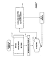
- Open loop control of the compressed air recirculation valve 22 of another embodiment of the present invention is illustrated by the flowchart of Figure 2.
- Input data including the degree of opening of the exhaust gas recirculation valve 43 and the degree of opening of the variable nozzle turbine, are collected in step 100.
- the compressed gas recirculation valve opening is set to zero in step 101.
- the engine speed (Ne) as measured by the engine speed sensor 44 is compared to a predetermined Ne threshold (Ne(setting)). If Ne is less than the threshold Ne(setting) then the recirculation valve 22 is opened in step 103.
- Closed loop control of the compressed air recirculation valve 22 of another embodiment of the present invention is illustrated by the flowchart of Figure 3.
- the first four steps 100,101,102 and 103 are the same as described above for open loop control.
- the compressor inlet pressure P1C as measured by sensor 45 is compared to a threshold pressure P1C(setting) in step 104. If above the threshold, the logic returns to step 103. If below the threshold (in a more severe surge condition), the logic proceeds to step 105 wherein data is collected on the exhaust gas recirculation rate (EGR) by determining the difference between engine inlet pressure (P1E) as measured by sensor 47 and turbine inlet pressure (P1T) as measured by sensor 48, as shown in Figure 4.
- EGR exhaust gas recirculation rate
- a step 106 the EGR is compared to an exhaust gas recirculation threshold EGR(setting). If the EGR is greater than EGR(setting) then the subroutine ends. If the EGR is less than EGR(setting) then the logic proceeds to step 107 wherein the exhaust gas recirculation valve 43 is opened or, alternatively, the variable nozzle turbine is closed and the compressed air recirculation valve 22 is opened. EGR is compared again to EGR(setting) in a step 108 and if still less than EGR(setting), the logic returns to step 107. The exhaust gas recirculation valve 43 is opened further, or the compressed air recirculation valve 22 is opened further. If EGR is greater than EGR(setting) then the subroutine ends.
- EGR is greater than EGR(setting) then the subroutine ends.
- EGR rate is based on the "mass ratio" or "mole ratio.”
- the mass ratio is the mass flow of EGR versus the total mass flow within the engine cylinder.
- the desired EGR rate is about 10 to 15% at full load with medium engine speed, or high engine speed.
- the EGR rate is dropped to zero.
- the EGR rate would preferably be increased to about 20% at full load with low engine speed and more than 30% at full load with medium engine speed, or at high engine speed.
- a higher pressure ratio is necessary and the compressor more easily runs into surge.
- the EGR(setting) is a target rate that is related to the NOx reduction rate in the cylinders. If the EGR rate is lower than the target value, NOx contents at the engine exhaust manifold will be too high and cannot clear the emission target values even with use of a de-NOx catalyst.
- FIG. 5-10 Other embodiments of the compressor active surge control system of the present invention are illustrated schematically in Figures 5-10.
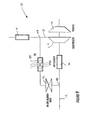
- an air cleaner 49 is positioned upstream of the mixer 20 in the inlet line 12 and the dedicated air cooler 50 is positioned in the compressed air recirculation line 18.
- the junction between the first end 27 of the recirculation line 18 and the discharge line 13 is upstream of the intercooler 19.
- the mixer 20 is also an air cleaner which eliminates the need for an independent mixer.
- the junction of the first end 27 of the recirculation line 18 and the discharge line 12 is downstream of the intercooler 19, allowing the intercooler to also cool the compressor discharge air prior to its recirculation.
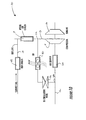
- the mixer 20 is an air cleaner that is downstream of the junction between the inlet line 12 and the second end 28 of the recirculation line 18.
- the mixer 20 is an air cleaner and also serves as an air cooler, allowing the junction between the recirculation line 18 and discharge line 13 to be upstream of the cooler 19.
- the cooler 50 is in the compressed air recirculation line 18 and is a tip turbine fan.
- the tip turbine fan absorbs some of the thermal energy of the compressed air allowing it to be cooled more easily by the air cleaner type mixer 20.
- Figure 10 Another embodiment is shown in Figure 10, which is similar to the embodiment of Figure 9 except for the use of the exhaust gas recirculation cooler 42.
- the exhaust gas cooler 42 can aid the intercooler 19 if the cooling effectiveness of the intercooler is not enough.
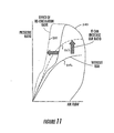
- Figure 11 illustrates the expansion of the working area of the compressor 11 when the surge control system 10 of the present invention is used.
- the working envelope without compressed air recirculation is defined by,a solid line 200.
- the solid line 202 defines the compressor operating line without exhaust gas recirculation.
- the dashed line 203 represents how the operating line is shifted with exhaust gas recirculation. It can be seen that the operating line at low air flow conditions is into the surge area of the map.
- the dotted line 201 shows how the operating envelope is expanded by compressed air recirculation in accordance with the invention; as a result, even with exhaust gas recirculation, the operating line 203 falls within the non-surge region of the map.
- Expansion of the operating range of the compressor system is enhanced through cooling of the recirculated air and/or mixing of the recirculated air with the intake air such that substantially uniform flow conditions exist at the entrance to the compressor. Without adequate mixing, non-uniform flow conditions would tend to hurt compressor efficiency.
Landscapes
- Engineering & Computer Science (AREA)
- Chemical & Material Sciences (AREA)
- Combustion & Propulsion (AREA)
- Mechanical Engineering (AREA)
- General Engineering & Computer Science (AREA)
- Physics & Mathematics (AREA)
- Thermal Sciences (AREA)
- Exhaust-Gas Circulating Devices (AREA)
- Supercharger (AREA)
Description
- The present invention is related to the use of compressor systems (e.g., turbochargers) for boosting the power output of combustion engines, and in particular to the use of recirculated compressor discharge air to facilitate the operation of such compressors.
- Vehicle engine turbochargers provide an advantageous boost to engine power, especially at higher engine speeds. A turbocharger uses the exhaust gasses from an engine to drive a turbine that drives a compressor, which, in turn, increases the pressure of the engine intake air. The compressed engine intake air results in the boost of engine power. In some turbocharger engine systems, a portion of the exhaust gases from the engine is recirculated back to the intake of the engine to control emissions. In other systems, the compressor drive may be electrically assisted or the turbine may include a variable geometry nozzle to further increase performance. A control of boost presure is described in GB-2163483 or JP-2001-355453.
- In certain circumstances, a turbocharger can experience what is commonly referred to as a "surge" condition. Generally, surge occurs when the compressor is driven into low-flow, high pressure-ratio conditions, the result of which is that the compressor blades are forced to operate at such high incidence angles that significant flow separation occurs on the blades. Surge can result in severe aerodynamic fluctuations within the compressor of the turbocharger and can even cause damage to the engine or its intake pipe system.
- In one instance, surge can occur when compressor exhaust gas recirculation flow is relatively high at low engine speed. The remaining engine cylinder volume for fresh air at this point becomes smaller. In order to maintain engine torque and load performance, the boosting pressure needs to increase (thereby increasing air density) to keep the same mass flow rate of fresh air into the engine. As a result, the compressor has to work at a relatively higher load and pressure ratio, while the airflow remains relatively low.
- In another instance, surge can occur when a relatively high specific power output (such as 70 to 80 kilowatts per liter) is required of the engine and electrically assisted boosting of the compressor is employed. In still another instance, surge can occur when a quick compressor response is required using electrical boosting and/or the use of variable turbine nozzle vanes. In another instance, sudden deceleration of the engine due to closing of the throttle valve can result in surge.
- It would be advantageous, therefore, to reduce the occurrence of surge in a turbocharger. Reducing such occurrence would allow an expanded range of conditions in which the turbocharger would be able to boost engine power.
- Having thus described the invention in general terms, reference will now be made to the accompanying drawings, which are not necessarily drawn to scale, and wherein:
- Figure 1 is a schematic of a surge control system of one embodiment of the present invention;
- Figure 2 is a schematic of open loop control logic of another embodiment of the surge control system of the present invention;
- Figure 3 is a schematic of a closed loop control logic of still another embodiment of the surge control system of the present invention;
- Figure 4 is a schematic of a continuation of the closed loop control illustrated in Figure 3;
- Figure 5 is a schematic of a surge control system of another embodiment of the present invention including an air cleaner upstream of a junction between the inlet line and the recirculation line;
- Figure 6 is a schematic of a surge control system of still another embodiment of the present invention including an air cleaner serving as a mixer;
- Figure 7 is a schematic of a surge control system of yet another embodiment of the present invention including an air cleaner as mixer and a dedicated gas recirculation cooler;
- Figure 8 is a schematic of a surge control system of another embodiment of the present invention including an air cleaner serving also as a mixer and as a cooler;
- Figure 9 is a schematic of a surge control system of another embodiment of the present invention including a tip turbine fan cooler;
- Figure 10 is a schematic of a surge control system of still another embodiment of the present invention including the use of an exhaust gas recirculation line cooler; and
- Figure 11 is a graphical depiction of the improved compressor operating range resulting from compressed air recirculation by the surge control system of the present invention.
- The present inventions now will be described more fully hereinafter with reference to the accompanying drawings, in which some, but not all embodiments of the invention are shown. Indeed, the invention may be embodied in many different forms and should not be construed as limited to the embodiments set forth herein; rather, these embodiments are provided so that this disclosure will satisfy applicable legal requirements. Like numbers refer to like elements throughout.
- A compressor active
surge control system 10 of one embodiment of the present invention, as shown in Figure 1, includes a compressor 11, acompressor inlet line 12, acompressor discharge line 13, arecirculation line 18 connecting the inlet and discharge lines, anair cooler 50 and anair mixer 20. Generally, the compressor 11 supplies compressed air through theline 13 to acombustion engine 14 so as to increase power output by the engine. Anexhaust gas line 15 conducts exhaust from theengine 14 to aturbine 16 which drives the compressor 11. An exhaustgas recirculation line 17 may optionally be used to recirculate exhaust gas back to theengine 14's intake for control of engine emissions. - The compressor inlet pipe or
line 12 is connected to an ambient air source, such as by being connected to an intake scoop (not shown) beneath the hood of an automobile. The term "ambient" as used herein broadly defines air from a general supply of air, and not necessarily air at a temperature, pressure or cleanliness of the surrounding environment. Generally, then, the ambient air is any air (or other gas) that is useable for combustion, but is at a pressure lower than the air discharged from the compressor 11. - The term "line" as used herein may include pipes, tubes, hoses or any other conduit, device or method for conducting air or other fluids from one place to another. In addition, although the term "line" may be used in singular form, it may indicate use of several lines, tubes, conduits, portions or combinations thereof, that are effective in conducting a fluid (such as air) from one place to another. For instance, the present invention need not be limited to a single
compressor inlet line 12 as multiple inlet hoses could be used depending upon the amount of ambient air required for compression and combustion. Also, as used herein "line" does not necessarily indicate that the pipe or hose travels directly from one place to another, but could also include intervening stops for supplying other devices, branches or twists and turns. - The
inlet line 12, which is downstream of an air filter (not shown) in the embodiment depicted in Figure 1, is connected at a downstream end to therecirculation mixer 20. As illustrated, themixer 20 includes a length ofpipe 26 containing a cylindrical filter or baffle 25 housed within the pipe. Defined by the cylindrical baffle is a central opening that extends co-axially with the opening of thepipe 26. The upstream end of the mixer pipe is fitted to the downstream end of theinlet line 12 while the opposite, downstream end of the mixer pipe is fitted to aninlet duct 23. The inlet duct is part of a shroud orhousing 24 of the compressor 11 and can have a diameter the same as themixer pipe 26. - Defmed within the sidewall of the
mixer pipe 26 is an opening to which asecond end 28 of therecirculation line 18 is attached. Connection with the recirculation line allows entry of the recirculated air into themixer 20 so that it can be mixed with the main, ambient air supply from theinlet line 12, as will be described in more detail below. An advantage of the cylindrical baffle or filter of themixer 20 is that its central opening is oriented with the direction of the ambient air so that it mixes with the recirculated airflow with minimal impedance of the flow. - Although the
mixer 20 is illustrated in Figure 1 as having thepipe 26 and cylindrical filter 25, other mixer devices may also be employed. For instance, a baffle could be used that does not filter, but redirects airflow to cause turbulence and mixing. Also, conventional, pre-existing air filters could be used such as off-the-shelf paper or oil-impregnated foam filters. In such a case, an additional opening may be formed in the filter and a fitting used to attach thesecond end 28 of therecirculation line 18. In another alternative (as described below) flow from theinlet line 12 and therecirculation line 18 is combined upstream of themixer 20 by a direct connection between the lines. - Referring again to the embodiment illustrated in Figure 1, the compressor 11 is a rotationally driven compressor having a plurality of
compressor blades 30 mounted to arotatable shaft 31 driven by theturbine 16. Avolute 24 surrounds the compressor for receiving pressurized air discharged from the compressor. A discharge oroutlet duct 32 is connected from thevolute 24 to an upstream end of thedischarge line 13. - As noted above, the compressor 11 is driven by the
turbine 16. Theturbine 16 includes aninlet volute 33 that receives exhaust gases from theengine 14 via theline 15 and via aninlet 35 to the volute. The turbine includesturbine blades 34 mounted on theshaft 31. The turbine housing defines aturbine outlet 36 through which the exhaust gases are discharged after passing through the turbine. Theturbine outlet 36 is attached to the downstream exhaust system (not shown) of the power plant. - Although the compressor in the illustrated embodiment is shown as being driven by a turbine powered by engine exhaust gas (e.g., a turbocharger), other alternative drives could be used to power the compressor 11. For instance, the compressor could be mechanically driven by the engine drive shaft (e.g., a supercharger) or the compressor could be driven by an electrical motor. In another instance, the turbine drive of the illustrated embodiment could be assisted by another drive, such as an electrical drive (electrically assisted) or the engine drive shaft.
- Returning to the intake air compression portion of the
system 10, theoutlet duct 32 of the compressor is connected to dischargeline 13 which extends to theair cooler 19. The illustratedair cooler 19 is an intercooler which typically houses a plurality of tubes through which the relatively hot, compressed air flows from the compressor 11. Generally, ambient air (or water) passes over the tubes and between fins that are attached to the tubes. Heat is then transferred from the hot tubes and fins to the cool ambient air. Theair cooler 19 includes an upstream, inlet opening 37 which is attached to thedischarge line 13 and a downstream, outlet opening 38 that is attached to a downstream portion of the discharge line 13 (which may also be referred to as an engine intake line). It should be noted that other types of air coolers or heat exchangers could also be used in lieu of the illustrated intercooler. - The
discharge line 13 includes a connection to afirst end 27 of therecirculation line 18, anon-return valve 39, and a connection to the exhaustgas recirculation line 17. Thenon-return valve 39 is a one-way valve that prevents backflow of the recirculated exhaust gases and the engine intake air. The exhaustgas recirculation line 17 includes afirst end 40 connected to theexhaust gas line 15 and asecond end 41 connected to the downstream portion of thedischarge line 13. The exhaust gas recirculation system includes itsown cooler 42 andcontrol valve 43. The exhaustgas recirculation valve 43 controls the flow of recirculated exhaust gases and may be positioned upstream, or downstream, of theexhaust gas cooler 42. Operation of the exhaustgas recirculation valve 43 is controlled by an engine control unit 21, as will be described in more detail below. - As mentioned above, the compressed
air recirculation line 18 has itsfirst end 27 connected to thedischarge line 13 upstream of theair cooler 19. The opposite,second end 28 of the compressedair recirculation line 18 is connected to themixer 20, as also described above. Arecirculation valve 22 is positioned between theends air recirculation line 18. The recirculation valve is connected in communication with, and controlled by, the engine control unit 21, as indicated by the dashed line. Therecirculation valve 22 in one embodiment is open-loop controlled by a pneumatic actuator; in another embodiment thevalve 22 can be closed-loop controlled by a rotary electric actuator. Also within therecirculation line 18, is adedicated air cooler 50 for cooling recirculated air. - In addition to being connected to the
valves engine speed sensor 44, a compressor inlet pressure sensor 45 and a compressoroutlet pressure sensor 46. For open loop control, opening of therecirculation valve 22 is a function of the engine speed as measured by thesensor 44 and the boost pressure as measured bysensor 46. For closed loop control, opening of the valve is a function of engine speed and the compressor inlet pressure as measured by sensor 45, which is capable of sensing surge. As another alternative, therecirculation valve 22 may be controlled in response to the exhaust gas recirculation rate (intake throttling) or the difference in gas pressure between the engine inlet (as measured by engine inlet pressure sensor 46) and turbine inlet (as measured by a turbine inlet pressure sensor 47). - Control of the compressed
air recirculation valve 22 opening may also be coordinated with opening of the exhaust-gas recirculation valve 43 and control of the variable turbine nozzle to optimize air flow and exhaust gas recirculation rates. For instance, the compressedair recirculation valve 22 can be used to absorb the extra turbine power when the variable turbine nozzle is suddenly closed during engine braking. - Open loop control of the compressed
air recirculation valve 22 of another embodiment of the present invention is illustrated by the flowchart of Figure 2. Input data, including the degree of opening of the exhaustgas recirculation valve 43 and the degree of opening of the variable nozzle turbine, are collected instep 100. The compressed gas recirculation valve opening is set to zero instep 101. Then instep 102, the engine speed (Ne) as measured by theengine speed sensor 44 is compared to a predetermined Ne threshold (Ne(setting)). If Ne is less than the threshold Ne(setting) then therecirculation valve 22 is opened instep 103. The amount of opening is defined by the following equation:
wherein RVO is the amount of compressed air recirculation valve opening, A is a predetermined constant, B is a predetermined constant, Ne is the engine speed and P2C is the outlet pressure measured bysensor 46. If Ne is determined to be more than the threshold Ne(setting) instep 102, the subroutine ends and therecirculation valve 22 is left closed. - Closed loop control of the compressed
air recirculation valve 22 of another embodiment of the present invention is illustrated by the flowchart of Figure 3. The first four steps 100,101,102 and 103 are the same as described above for open loop control. However, after opening the compressedair recirculation valve 22, the compressor inlet pressure P1C as measured by sensor 45 is compared to a threshold pressure P1C(setting) instep 104. If above the threshold, the logic returns to step 103. If below the threshold (in a more severe surge condition), the logic proceeds to step 105 wherein data is collected on the exhaust gas recirculation rate (EGR) by determining the difference between engine inlet pressure (P1E) as measured bysensor 47 and turbine inlet pressure (P1T) as measured by sensor 48, as shown in Figure 4. - In a
step 106 the EGR is compared to an exhaust gas recirculation threshold EGR(setting). If the EGR is greater than EGR(setting) then the subroutine ends. If the EGR is less than EGR(setting) then the logic proceeds to step 107 wherein the exhaustgas recirculation valve 43 is opened or, alternatively, the variable nozzle turbine is closed and the compressedair recirculation valve 22 is opened. EGR is compared again to EGR(setting) in astep 108 and if still less than EGR(setting), the logic returns to step 107. The exhaustgas recirculation valve 43 is opened further, or the compressedair recirculation valve 22 is opened further. If EGR is greater than EGR(setting) then the subroutine ends. - One measure of EGR rate is based on the "mass ratio" or "mole ratio." The mass ratio is the mass flow of EGR versus the total mass flow within the engine cylinder. Generally, the desired EGR rate is about 10 to 15% at full load with medium engine speed, or high engine speed. At full load and low engine speed for European and North American commercial vehicles the EGR rate is dropped to zero. For vehicles having higher emission requirements, the EGR rate would preferably be increased to about 20% at full load with low engine speed and more than 30% at full load with medium engine speed, or at high engine speed. Typically, to maintain high mass flow of fresh air, a higher pressure ratio is necessary and the compressor more easily runs into surge.
- For the EGR(setting) at a given engine condition (speed and load), the EGR(setting) is a target rate that is related to the NOx reduction rate in the cylinders. If the EGR rate is lower than the target value, NOx contents at the engine exhaust manifold will be too high and cannot clear the emission target values even with use of a de-NOx catalyst.
- Other embodiments of the compressor active surge control system of the present invention are illustrated schematically in Figures 5-10. In one embodiment shown in Figure 5, an
air cleaner 49 is positioned upstream of themixer 20 in theinlet line 12 and thededicated air cooler 50 is positioned in the compressedair recirculation line 18. The junction between thefirst end 27 of therecirculation line 18 and thedischarge line 13 is upstream of theintercooler 19. - In another embodiment shown in Figure 6, the
mixer 20 is also an air cleaner which eliminates the need for an independent mixer. The junction of thefirst end 27 of therecirculation line 18 and thedischarge line 12 is downstream of theintercooler 19, allowing the intercooler to also cool the compressor discharge air prior to its recirculation. In still another embodiment shown in Figure 7, themixer 20 is an air cleaner that is downstream of the junction between theinlet line 12 and thesecond end 28 of therecirculation line 18. In an embodiment shown in Figure 8, themixer 20 is an air cleaner and also serves as an air cooler, allowing the junction between therecirculation line 18 anddischarge line 13 to be upstream of the cooler 19. - In yet another embodiment shown in Figure 9, the cooler 50 is in the compressed
air recirculation line 18 and is a tip turbine fan. The tip turbine fan absorbs some of the thermal energy of the compressed air allowing it to be cooled more easily by the aircleaner type mixer 20. Another embodiment is shown in Figure 10, which is similar to the embodiment of Figure 9 except for the use of the exhaustgas recirculation cooler 42. In this embodiment, the exhaust gas cooler 42 can aid theintercooler 19 if the cooling effectiveness of the intercooler is not enough. - Surge control by the present invention has many advantages. For instance, Figure 11 illustrates the expansion of the working area of the compressor 11 when the
surge control system 10 of the present invention is used. The working envelope without compressed air recirculation is defined by,asolid line 200. Thesolid line 202 defines the compressor operating line without exhaust gas recirculation. The dashedline 203 represents how the operating line is shifted with exhaust gas recirculation. It can be seen that the operating line at low air flow conditions is into the surge area of the map. The dottedline 201 shows how the operating envelope is expanded by compressed air recirculation in accordance with the invention; as a result, even with exhaust gas recirculation, the operatingline 203 falls within the non-surge region of the map. Expansion of the operating range of the compressor system is enhanced through cooling of the recirculated air and/or mixing of the recirculated air with the intake air such that substantially uniform flow conditions exist at the entrance to the compressor. Without adequate mixing, non-uniform flow conditions would tend to hurt compressor efficiency. - Many modifications and other embodiments of the inventions set forth herein will come to mind to one skilled in the art to which these inventions pertain having the benefit of the teachings presented in the foregoing descriptions and the associated drawings. Therefore, it is to be understood that the inventions are not to be limited to the specific embodiments disclosed and that modifications and other embodiments are intended to be included within the scope of the appended claims. Although specific terms are employed herein, they are used in a generic and descriptive sense only and not for purposes of limitation.
Claims (19)
- A system (10) for supplying compressed air to an internal combustion engine (14) so as to boost power output by the engine, said system comprising:a compressor (11) having a rotary compression device (30) positioned in a housing (24) defining an air inlet (23) and a compressed air outlet (32), wherein the air inlet (23) is configured to supply inlet air to the rotary compression device, wherein the rotary compression device is configured to compress the inlet air and wherein the compressed air outlet is configured to allow the compressed air to exit the housing for supply to an intake of the engine;a recirculation line (18) arranged to recirculate a portion of the compressed air discharged from the compressed air outlet (32) back to the compressor air inlet (23);a recirculation valve (22) disposed in the recirculation line (18) and operable to control rate of flow through the recirculation line, the recirculation valve being controllable via control signals;a programmed controller (21) in communication with the recirculation valve (22) and programmed to send control signals to the recirculation valve to open the recirculation valve so as to recirculate compressed air through the recirculation line (18) to the compressor air inlet (23) when the engine is operating below a threshold engine speed, and to maintain the recirculation valve closed so as to prevent recirculation when the engine is operating above said threshold engine speed; andan air cooling device (50) connected in fluid communication with the recirculation line (18) and operable to cool the recirculated air upstream of the compressor air inlet (23), wherein the cooled air from the recirculation line is combined with the inlet air upstream of the compressor air inlet, the cooled recirculated air reducing occurrence of compressor surge.
- The system of Claim 1, wherein the controller (21) is programmed to control an amount of the valve opening (RVO) of the recirculation valve (22) as a function of the engine speed and the outlet air pressure.
- The system of Claim 2, wherein the controller (21) is programmed to control the amount of valve opening (RVO) according to the equation:

wherein A and B are predetermined constants, Ne is the engine speed and P2C is the outlet air pressure. - The system of Claim 1, further comprising a compressor discharge line (13) connecting the engine intake and the compressor outlet (32), wherein a first end (27) of the recirculation line (18) is connected To the compressor discharge line (13) and wherein the air cooling device (50) is connected in fluid communication with the compressor discharge line (13) upstream of the recirculation line (18) first end and compressor discharge line (13) connection.
- The system of Claim 1, further comprising a compressor inlet line (12) connected to the compressor air inlet (23), wherein a second end (28) of the recirculation line (18) is connected to the compressor inlet line (12).
- The system of Claim 5, further comprising a mixing device (20) connected to the recirculation line (18) and the compressor inlet line (12) und operable for mixing cooled, recirculated air from the recirculation line with inlet air from the compressor inlet line.
- The system of Claim 6, wherein the mixing device (20) is an air cleaner.
- The system of Claim 6, further comprising an air cleaner (49) connected to the compressor inlet line (12) upstream of the mixing device (20).
- The system of Claim 1, further comprising a compressor discharge line (13) connecting the engine intake and the compressor outlet (32), wherein a first end (27) of the recirculation line (18) is connected to the compressor discharge line (13) and a second end (28) of the recirculation line is in fluid communication with the compressor air inlet (23), and wherein the air cooling device (50) is disposed between the first end (27) and the second end (28) of the recirculation line (18).
- The system of Claim 1, further comprising a compressor inlet line (12) connected to the compressor air inlet (23), the recirculation line (18) being connected to the compressor inlet line (12), and further comprising an air cleaner (49) connected to the compressor inlet line (12) downstream of the recirculation line (18) and compressor inlet line (12) connection, and wherein the air cleaner (49) is also configured to mix recirculated and inlet air.
- The system of Claim 10, further comprising a compressor discharge line (13) connecting the engine intake and the compressor outlet (32), wherein the recirculation line (18) is connected to the compressor discharge line (13).
- The system of Claim 11, further comprising a second air cooler (19) connected in fluid communication with the compressor discharge line (13) downstream of the recirculation line (18) and compressor discharge line (13) connection.
- The system of Claim 11, further comprising an exhaust gas recirculation line (17) connected to the compressor discharge line (13) downstream of the connection between the recirculation line (18) and compressor discharge line (13).
- The system of Claim 13, further comprising an exhaust gas cooling device (42) connected to the exhaust gas recirculation line (17).
- The system of Claim 14, further comprising a second air cooling device (19) connected to the compressor discharge line (13) downstream of the recirculation line (18) first end (27) and compressor discharge line (13) connection and upstream of the exhaust gas recirculation line (17) and compressor discharge line (13) connection.
- A method of actively controlling compressor surge in an engine system wherein air is compressed in a compressor (11) and supplied to an intake of an internal combustion engine (14), said surge controlling method comprising the steps of:supplying air to a compressor inlet (23) of the compressor (11);compressing the air in the compressor;discharging the compressed air from the compressor through a compressor discharge line (13) to the intake of the internal combustion engine (14);providing a recirculation line (18) connecting the compressor discharge line (13) to the compressor inlet (23);providing a controllable recirculation valve (22) in The recirculation line (18) for controlling an amount of flow through the recirculation line;opening the valve (22) and recirculating compressed air from the compressor discharge line (13) to the compressor inlet (23) when the engine (14) is operating below a threshold engine speed, and maintaining the valve (22) closed so as to prevent recirculation when the engine (14) is operating above said threshold engine speed; andcooling the recirculated air prior to delivering the recirculated air to the compressor inlet (23).
- The method of Claim 16, further comprising mixing the cooled recirculated air with the air being supplied to the compressor inlet (23) such that flow conditions entering the compressor (11) are more uniform than would exist without said mixing.
- The method of Claim 16, wherein an amount of the valve opening (RVO) of the recirculation valve (22) is a function of the engine speed and the outlet ait pressure of the compressed air discharged from the compressor (11).
- The method of Claim 18, wherein the amount of valve opening (RVO) is controlled according to the equation:

Applications Claiming Priority (1)
| Application Number | Priority Date | Filing Date | Title |
|---|---|---|---|
| PCT/US2003/025029 WO2005017329A1 (en) | 2003-08-08 | 2003-08-08 | Surge control system for a compressor |
Publications (2)
| Publication Number | Publication Date |
|---|---|
| EP1651847A1 EP1651847A1 (en) | 2006-05-03 |
| EP1651847B1 true EP1651847B1 (en) | 2006-11-29 |
Family
ID=34192566
Family Applications (1)
| Application Number | Title | Priority Date | Filing Date |
|---|---|---|---|
| EP03818232A Expired - Lifetime EP1651847B1 (en) | 2003-08-08 | 2003-08-08 | Surge control system for a compressor |
Country Status (7)
| Country | Link |
|---|---|
| US (1) | US7281378B2 (en) |
| EP (1) | EP1651847B1 (en) |
| JP (1) | JP2007528956A (en) |
| CN (1) | CN1820133A (en) |
| AU (1) | AU2003259733A1 (en) |
| DE (1) | DE60310142T2 (en) |
| WO (1) | WO2005017329A1 (en) |
Cited By (2)
| Publication number | Priority date | Publication date | Assignee | Title |
|---|---|---|---|---|
| US9157446B2 (en) | 2013-01-31 | 2015-10-13 | Danfoss A/S | Centrifugal compressor with extended operating range |
| US10962016B2 (en) | 2016-02-04 | 2021-03-30 | Danfoss A/S | Active surge control in centrifugal compressors using microjet injection |
Families Citing this family (50)
| Publication number | Priority date | Publication date | Assignee | Title |
|---|---|---|---|---|
| AU2003259733A1 (en) | 2003-08-08 | 2005-03-07 | Honeywell International Inc. | Surge control system for a compressor |
| US7614232B2 (en) * | 2004-07-23 | 2009-11-10 | General Electric Company | Turbocharger recirculation valve |
| WO2006122306A2 (en) * | 2005-05-11 | 2006-11-16 | Borgwarner Inc. | Engine air management system |
| US8307645B2 (en) * | 2005-11-02 | 2012-11-13 | General Electric Company | Apparatus and method for avoidance of turbocharger surge on locomotive diesel engines |
| DE102005054525A1 (en) * | 2005-11-14 | 2007-05-16 | Porsche Ag | Method and control unit for controlling a turbocharger with turbine-side boost pressure control and a recirculation valve |
| EP2074296A4 (en) * | 2006-10-02 | 2016-08-17 | Mack Trucks | Engine with charge air recirculation and method |
| US7644584B2 (en) * | 2006-11-30 | 2010-01-12 | Caterpillar Inc. | Method for modulating turbocharger braking |
| DE102007021702A1 (en) * | 2007-05-09 | 2008-11-13 | Dr. Ing. H.C. F. Porsche Aktiengesellschaft | Recirculation system for an exhaust gas turbocharger |
| CN101054921B (en) * | 2007-05-21 | 2010-07-07 | 哈尔滨工程大学 | Marine diesel engine turbocharger surge predictive control device and control method |
| US8151567B2 (en) * | 2007-05-29 | 2012-04-10 | Ford Global Technologies, Llc | Adaptive learning system and method of vane position for a variable geometry turbocharger |
| US8057949B2 (en) | 2007-08-16 | 2011-11-15 | Ford Global Technologies, Llc | Fuel cell stack flow diversion |
| GB0716329D0 (en) | 2007-08-21 | 2007-10-03 | Compair Uk Ltd | Improvements in compressors control |
| DE102007051845B4 (en) | 2007-10-30 | 2013-04-04 | Continental Automotive Gmbh | Turbocharger and method for generating a pre-whirl before a compressor of the turbocharger |
| FR2924170B1 (en) * | 2007-11-22 | 2009-11-20 | Renault Sas | SUPERIOR INTERNAL COMBUSTION ENGINE PROTECTS AGAINST COMPRESSOR PUMPING. |
| US7529614B1 (en) | 2007-11-30 | 2009-05-05 | Delphi Technologies, Inc. | System and method for turbo compressor recirculation valve control |
| BRPI0820894A2 (en) * | 2007-12-14 | 2015-06-16 | Carrier Corp | Process for controlling operation of a heating, ventilation and air conditioning system and heating, ventilation and air conditioning system |
| JP2010265810A (en) | 2009-05-14 | 2010-11-25 | Mitsubishi Electric Corp | Control device for internal combustion engine |
| US10196993B2 (en) * | 2009-09-08 | 2019-02-05 | Ge Global Sourcing Llc | System and method for operating a turbocharged engine |
| ES2931034T3 (en) * | 2009-12-23 | 2022-12-23 | ||
| JP5586245B2 (en) * | 2010-01-20 | 2014-09-10 | 日立造船株式会社 | Intake air cooling system for marine internal combustion engines |
| IT1401663B1 (en) | 2010-08-31 | 2013-08-02 | Nuovo Pignone Spa | DEVICE AND METHOD TO DETECT A OVERCURRENT IN A COMPRESSOR AND MOVE A CURRENT MARGIN. |
| CN102042092B (en) * | 2010-12-06 | 2013-05-29 | 哈尔滨工业大学 | Surge protection method for switching control of air quantity of air compressor of turbocharging system |
| FR2970523B1 (en) * | 2011-01-17 | 2015-06-05 | Peugeot Citroen Automobiles Sa | AIR INTAKE LINE OF A COMBUSTION ENGINE, ASSOCIATED AIR FILTER CASE, AND MOTOR VEHICLE COMPRISING SUCH A LINE |
| MX2013009154A (en) * | 2011-02-09 | 2013-12-16 | Synapse Engineering Inc | Turbocharger control strategy to in increase exhaust manifold pressure. |
| US8739530B2 (en) * | 2011-11-10 | 2014-06-03 | Ford Global Technologies, Llc | Compressor flow control |
| US9243550B2 (en) * | 2012-03-12 | 2016-01-26 | Ford Global Technologies, Llc | Turbocharger compressor inlet flow control |
| KR101858643B1 (en) | 2012-03-23 | 2018-05-16 | 한화테크윈 주식회사 | Method of controlling compressor system and compressor system for protecting surge |
| CN102588315B (en) * | 2012-03-30 | 2014-10-15 | 西安陕鼓动力股份有限公司 | Automatic surge testing method for turbine compressor |
| CN102913331B (en) * | 2012-10-29 | 2015-06-17 | 潍柴动力股份有限公司 | Engine system as well as running state optimal control method and device thereof |
| FR3002595B1 (en) * | 2013-02-25 | 2016-12-23 | Peugeot Citroen Automobiles Sa | AIR FILTER COMPRISING AN AIR INTAKE LINE OF AN ENGINE OF A MOTOR VEHICLE |
| US9261051B2 (en) * | 2013-08-13 | 2016-02-16 | Ford Global Technologies, Llc | Methods and systems for boost control |
| US9091202B2 (en) * | 2013-08-13 | 2015-07-28 | Ford Global Technologies, Llc | Methods and systems for boost control |
| US9631629B2 (en) | 2013-09-11 | 2017-04-25 | Ford Global Technologies, Llc | Methods and systems for low-pressure exhaust gas recirculation |
| EP2902613B1 (en) * | 2014-01-31 | 2018-01-31 | Mann + Hummel Gmbh | Air noise reduction device |
| JP6295996B2 (en) * | 2014-06-19 | 2018-03-20 | トヨタ自動車株式会社 | Internal combustion engine with a supercharger |
| US9551276B2 (en) * | 2014-08-14 | 2017-01-24 | Ford Global Technologies, Llc | Methods and systems for surge control |
| US20160319810A1 (en) * | 2015-04-30 | 2016-11-03 | Atlas Copco Comptec, Llc | Gas handling system and method for efficiently managing changes in gaseous conditions |
| CN104879210A (en) * | 2015-06-04 | 2015-09-02 | 安徽江淮汽车股份有限公司 | Supercharger and anti-surge control device and method thereof |
| DE102015007758A1 (en) | 2015-06-17 | 2016-01-21 | Daimler Ag | Compressor, in particular for an exhaust gas turbocharger of an internal combustion engine |
| CN105673194B (en) * | 2016-01-12 | 2018-04-06 | 中国第一汽车股份有限公司 | The method for diagnosing faults of engine charge relief valve obstruction |
| JP6650762B2 (en) * | 2016-01-15 | 2020-02-19 | 三菱重工業株式会社 | Internal combustion engine, control apparatus and method for internal combustion engine |
| SE539728C2 (en) * | 2016-03-17 | 2017-11-14 | Scania Cv Ab | A compressor arrangement supplying charged air to a combustion engine |
| FR3059720B1 (en) * | 2016-12-05 | 2020-01-24 | Renault S.A.S | METHOD FOR CONTROLLING AN ELECTRICALLY ASSISTED TURBOCHARGER |
| CN110249118B (en) * | 2017-02-14 | 2022-01-25 | 卡明斯公司 | Compressor Bypass Flow Arrangement |
| US10920656B2 (en) | 2017-06-09 | 2021-02-16 | Pratt & Whitney Canada Corp. | Internal combustion engine cooling system |
| US11560829B2 (en) | 2020-01-02 | 2023-01-24 | Caterpillar Inc. | Recirculation system for a power system that includes a plurality of turbochargers |
| US11174822B1 (en) | 2020-07-13 | 2021-11-16 | Cummins Power Generation Inc. | Turbocharger compressor bypass coaxial re-introduction system to optimize transient load response |
| CN113404707B (en) * | 2021-06-01 | 2023-11-03 | 中冶南方(黄石)气体有限公司 | A booster tower for space division |
| CN116181447B (en) * | 2022-05-10 | 2026-01-23 | 潍柴动力股份有限公司 | Gas machine |
| US20250216036A1 (en) * | 2023-12-28 | 2025-07-03 | Saudi Arabian Oil Company | Startup control system and method for centrifugal compressors |
Family Cites Families (12)
| Publication number | Priority date | Publication date | Assignee | Title |
|---|---|---|---|---|
| GB244312A (en) | 1925-03-27 | 1925-12-17 | Walter John Smith Dufton | An improved glazing or surfacing material for tiles, slabs, sheeting and other articles |
| DE3011203C2 (en) | 1980-03-22 | 1986-06-19 | Dr.Ing.H.C. F. Porsche Ag, 7000 Stuttgart | Supercharged internal combustion engine for motor vehicles |
| JPS60201025A (en) | 1984-03-27 | 1985-10-11 | Mazda Motor Corp | Suction system structure of engine with pressure wave supercharger |
| GB2163483A (en) | 1984-08-20 | 1986-02-26 | Solex | A supercharged I.C. engine air/fuel induction system |
| IT1256997B (en) * | 1990-05-25 | 1995-12-27 | Mtu Friedrichshafen Gmbh | SUPERCHARGING UNIT WITH COMMANDABLE SUPPLY AIR COMPRESSORS FOR AN ENDOTHERMAL ENGINE. |
| DE4118265A1 (en) | 1990-06-13 | 1991-12-19 | Volkswagen Ag | Power unit for vehicle - has devices keeping out foreign bodies before and after spiral-type pressure-charger |
| GB2246395A (en) | 1990-07-26 | 1992-01-29 | Garrett Automotive Limited | Noise attenuation in a turbocharger |
| US5269144A (en) | 1991-09-10 | 1993-12-14 | Detroit Diesel Corporation | Methanol fueled turbocharged diesel cycle internal combustion engine |
| US6327980B1 (en) * | 2000-02-29 | 2001-12-11 | General Electric Company | Locomotive engine inlet air apparatus and method of controlling inlet air temperature |
| JP2001355453A (en) | 2000-06-09 | 2001-12-26 | Shigeto Takemoto | Intake air cooling device for internal combustion engine with supercharger |
| US6324848B1 (en) * | 2000-09-21 | 2001-12-04 | Caterpillar Inc. | Turbocharger system to inhibit surge in a multi-stage compressor |
| AU2003259733A1 (en) | 2003-08-08 | 2005-03-07 | Honeywell International Inc. | Surge control system for a compressor |
-
2003
- 2003-08-08 AU AU2003259733A patent/AU2003259733A1/en not_active Abandoned
- 2003-08-08 CN CNA038268841A patent/CN1820133A/en active Pending
- 2003-08-08 WO PCT/US2003/025029 patent/WO2005017329A1/en not_active Ceased
- 2003-08-08 JP JP2005507903A patent/JP2007528956A/en active Pending
- 2003-08-08 EP EP03818232A patent/EP1651847B1/en not_active Expired - Lifetime
- 2003-08-08 DE DE60310142T patent/DE60310142T2/en not_active Expired - Lifetime
- 2003-08-08 US US10/566,491 patent/US7281378B2/en not_active Expired - Lifetime
Cited By (3)
| Publication number | Priority date | Publication date | Assignee | Title |
|---|---|---|---|---|
| US9157446B2 (en) | 2013-01-31 | 2015-10-13 | Danfoss A/S | Centrifugal compressor with extended operating range |
| US10184481B2 (en) | 2013-01-31 | 2019-01-22 | Danfoss A/S | Centrifugal compressor with extended operating range |
| US10962016B2 (en) | 2016-02-04 | 2021-03-30 | Danfoss A/S | Active surge control in centrifugal compressors using microjet injection |
Also Published As
| Publication number | Publication date |
|---|---|
| CN1820133A (en) | 2006-08-16 |
| AU2003259733A1 (en) | 2005-03-07 |
| WO2005017329A1 (en) | 2005-02-24 |
| US20070039320A1 (en) | 2007-02-22 |
| JP2007528956A (en) | 2007-10-18 |
| EP1651847A1 (en) | 2006-05-03 |
| DE60310142T2 (en) | 2007-10-04 |
| US7281378B2 (en) | 2007-10-16 |
| DE60310142D1 (en) | 2007-01-11 |
Similar Documents
| Publication | Publication Date | Title |
|---|---|---|
| US7281378B2 (en) | Surge control system for a compressor | |
| RU122448U1 (en) | EXHAUST GAS RECIRCULATION MIXER AND VEHICLE ENGINE SYSTEM (OPTIONS) | |
| EP1191216B1 (en) | Turbocharger with exhaust gas recirculation and method of operation | |
| US6701710B1 (en) | Turbocharged engine with turbocharger compressor recirculation valve | |
| CN204099044U (en) | Boosting explosive motor | |
| CN102121436B (en) | System and method for providing intake air to engine in vehicle | |
| JP4906847B2 (en) | Engine air management device | |
| US7127893B2 (en) | Internal combustion engine comprising a compressor in the induction tract | |
| US20070144170A1 (en) | Compressor having integral EGR valve and mixer | |
| EP2063097A1 (en) | Internal combustion engine having exhaust gas cooling in cooling jacket | |
| JP2019044777A5 (en) | ||
| CN101782015B (en) | Internal combustion engine with exhaust-gas turbocharging | |
| JPH11503507A (en) | Exhaust gas recirculation system for internal combustion engines | |
| CN1379172A (en) | piston internal combustion engine | |
| CN105587400A (en) | System And Method For A Turbocharger Driven Coolant Pump | |
| JP2010511117A (en) | Exhaust gas circulation system for supercharged combustion engine | |
| CN111894769A (en) | Engine system | |
| CN101994605B (en) | System using supplemental compressor for EGR | |
| US20070000248A1 (en) | Air induction system having bypass flow control | |
| EP3430269B1 (en) | A compressor arrangement supplying charged air to a combustion engine | |
| WO2009046292A2 (en) | System and method for air flow control in a turbocharger | |
| US11261767B2 (en) | Bifurcated air induction system for turbocharged engines | |
| CN110578632A (en) | Exhaust gas turbocharged internal combustion engine with exhaust gas recirculation and method for operating an internal combustion engine of said type | |
| US7008175B2 (en) | Radiator cooling fan replacement to increase engine efficiency | |
| JP2007127070A (en) | Supercharged internal combustion engine |
Legal Events
| Date | Code | Title | Description |
|---|---|---|---|
| PUAI | Public reference made under article 153(3) epc to a published international application that has entered the european phase |
Free format text: ORIGINAL CODE: 0009012 |
|
| 17P | Request for examination filed |
Effective date: 20060116 |
|
| AK | Designated contracting states |
Kind code of ref document: A1 Designated state(s): DE FR GB |
|
| GRAP | Despatch of communication of intention to grant a patent |
Free format text: ORIGINAL CODE: EPIDOSNIGR1 |
|
| GRAS | Grant fee paid |
Free format text: ORIGINAL CODE: EPIDOSNIGR3 |
|
| GRAA | (expected) grant |
Free format text: ORIGINAL CODE: 0009210 |
|
| DAX | Request for extension of the european patent (deleted) | ||
| RBV | Designated contracting states (corrected) |
Designated state(s): DE FR GB |
|
| AK | Designated contracting states |
Kind code of ref document: B1 Designated state(s): DE FR GB |
|
| REG | Reference to a national code |
Ref country code: GB Ref legal event code: FG4D |
|
| REF | Corresponds to: |
Ref document number: 60310142 Country of ref document: DE Date of ref document: 20070111 Kind code of ref document: P |
|
| ET | Fr: translation filed | ||
| PLBE | No opposition filed within time limit |
Free format text: ORIGINAL CODE: 0009261 |
|
| STAA | Information on the status of an ep patent application or granted ep patent |
Free format text: STATUS: NO OPPOSITION FILED WITHIN TIME LIMIT |
|
| 26N | No opposition filed |
Effective date: 20070830 |
|
| REG | Reference to a national code |
Ref country code: FR Ref legal event code: PLFP Year of fee payment: 14 |
|
| REG | Reference to a national code |
Ref country code: FR Ref legal event code: PLFP Year of fee payment: 15 |
|
| REG | Reference to a national code |
Ref country code: FR Ref legal event code: PLFP Year of fee payment: 16 |
|
| REG | Reference to a national code |
Ref country code: DE Ref legal event code: R082 Ref document number: 60310142 Country of ref document: DE Representative=s name: TBK, DE Ref country code: DE Ref legal event code: R081 Ref document number: 60310142 Country of ref document: DE Owner name: GARRETT TRANSPORTATION I INC., TORRANCE, US Free format text: FORMER OWNER: HONEYWELL INTERNATIONAL INC., MORRISTOWN, N.J., US |
|
| REG | Reference to a national code |
Ref country code: GB Ref legal event code: 732E Free format text: REGISTERED BETWEEN 20190725 AND 20190731 |
|
| REG | Reference to a national code |
Ref country code: DE Ref legal event code: R082 Ref document number: 60310142 Country of ref document: DE |
|
| PGFP | Annual fee paid to national office [announced via postgrant information from national office to epo] |
Ref country code: FR Payment date: 20190827 Year of fee payment: 17 Ref country code: DE Payment date: 20190830 Year of fee payment: 17 |
|
| PGFP | Annual fee paid to national office [announced via postgrant information from national office to epo] |
Ref country code: GB Payment date: 20190829 Year of fee payment: 17 |
|
| REG | Reference to a national code |
Ref country code: DE Ref legal event code: R119 Ref document number: 60310142 Country of ref document: DE |
|
| GBPC | Gb: european patent ceased through non-payment of renewal fee |
Effective date: 20200808 |
|
| PG25 | Lapsed in a contracting state [announced via postgrant information from national office to epo] |
Ref country code: FR Free format text: LAPSE BECAUSE OF NON-PAYMENT OF DUE FEES Effective date: 20200831 Ref country code: DE Free format text: LAPSE BECAUSE OF NON-PAYMENT OF DUE FEES Effective date: 20210302 |
|
| PG25 | Lapsed in a contracting state [announced via postgrant information from national office to epo] |
Ref country code: GB Free format text: LAPSE BECAUSE OF NON-PAYMENT OF DUE FEES Effective date: 20200808 |