EP1650966A2 - Projector alignment method and user interface - Google Patents
Projector alignment method and user interface Download PDFInfo
- Publication number
- EP1650966A2 EP1650966A2 EP05020784A EP05020784A EP1650966A2 EP 1650966 A2 EP1650966 A2 EP 1650966A2 EP 05020784 A EP05020784 A EP 05020784A EP 05020784 A EP05020784 A EP 05020784A EP 1650966 A2 EP1650966 A2 EP 1650966A2
- Authority
- EP
- European Patent Office
- Prior art keywords
- projector
- display surface
- further comprised
- leds
- respect
- Prior art date
- Legal status (The legal status is an assumption and is not a legal conclusion. Google has not performed a legal analysis and makes no representation as to the accuracy of the status listed.)
- Withdrawn
Links
Images



Classifications
-
- H—ELECTRICITY
- H04—ELECTRIC COMMUNICATION TECHNIQUE
- H04N—PICTORIAL COMMUNICATION, e.g. TELEVISION
- H04N17/00—Diagnosis, testing or measuring for television systems or their details
- H04N17/04—Diagnosis, testing or measuring for television systems or their details for receivers
-
- G—PHYSICS
- G03—PHOTOGRAPHY; CINEMATOGRAPHY; ANALOGOUS TECHNIQUES USING WAVES OTHER THAN OPTICAL WAVES; ELECTROGRAPHY; HOLOGRAPHY
- G03B—APPARATUS OR ARRANGEMENTS FOR TAKING PHOTOGRAPHS OR FOR PROJECTING OR VIEWING THEM; APPARATUS OR ARRANGEMENTS EMPLOYING ANALOGOUS TECHNIQUES USING WAVES OTHER THAN OPTICAL WAVES; ACCESSORIES THEREFOR
- G03B21/00—Projectors or projection-type viewers; Accessories therefor
- G03B21/14—Details
- G03B21/53—Means for automatic focusing, e.g. to compensate thermal effects
-
- H—ELECTRICITY
- H04—ELECTRIC COMMUNICATION TECHNIQUE
- H04N—PICTORIAL COMMUNICATION, e.g. TELEVISION
- H04N5/00—Details of television systems
- H04N5/74—Projection arrangements for image reproduction, e.g. using eidophor
-
- H—ELECTRICITY
- H04—ELECTRIC COMMUNICATION TECHNIQUE
- H04N—PICTORIAL COMMUNICATION, e.g. TELEVISION
- H04N9/00—Details of colour television systems
- H04N9/12—Picture reproducers
- H04N9/31—Projection devices for colour picture display, e.g. using electronic spatial light modulators [ESLM]
- H04N9/3191—Testing thereof
- H04N9/3194—Testing thereof including sensor feedback
Definitions
- This invention relates to a method for indicating required movement of a projector relative to a display surface, wherein the projector has an auto-focusing range, the method comprising; measuring the distance between the projector and the display surface, determining, from the measured distance and the auto focusing range, a required movement of the projector relative to the display surface, and providing feedback to indicate the required movement of the projector relative to the display surface.
- an embodiment of this invention fulfills these needs by providing a method for indicating required movement of a projector relative to a display surface, wherein the projector has an auto-focusing range, the method comprising; measuring the distance between the projector and the display surface, determining, from the measured distance and the auto focusing range, a required movement of the projector relative to the display surface, and providing feedback to indicate the required movement of the projector relative to the display surface.
- the feedback consists of utilizing various LED patterns to prompt the user to manually alter the screen aspect ratio/alignment of the projector.
- the projector system provides an easy to use interface to quickly achieve alignment of a projector in a single try and can be used to reduce the overall optics/focusing systems range requirements.
- the preferred projector alignment system offers the following advantages: ease-of-use; excellent projector alignment characteristics; excellent projector range determination characteristics; good durability; and good economy.
- these factors of ease-of-use, excellent projector alignment characteristics, and excellent projector range determination characteristics are optimized to an extent that is considerably higher than heretofore achieved in prior, known projector alignment systems.
- Figure 1 is a schematic illustration of a projector alignment method and user interface, according to one embodiment of the present invention
- Figure 2 is a schematic illustration of a visual interface that guides the user to achieve clockwise alignment, according to another embodiment of the present invention
- Figure 3 is a schematic illustration of a visual interface that guides the user to achieve further clockwise alignment, according to another embodiment of the present invention.
- Figure 4 is a schematic illustration of a visual interface that guides the user to achieve counterclockwise alignment, according to another embodiment of the present invention.
- Figure 5 is a schematic illustration of a visual interface that guides the user to achieve further counterclockwise alignment, according to another embodiment of the present invention.
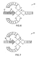
- Figure 6 is a schematic illustration of a visual interface that guides the user to achieve forward alignment, according to another embodiment of the present invention.
- Figure 7 is a schematic illustration of a visual interface that guides the user to achieve further forward alignment, according to another embodiment of the present invention.
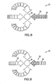
- Figure 8 is a schematic illustration of a visual interface that guides the user to achieve backward alignment, according to another embodiment of the present invention.
- Figure 9 is a schematic illustration of a visual interface that guides the user to achieve further backward alignment, according to another embodiment of the present invention.
- Figure 10 is a schematic illustration of a visual interface that informs the user that the alignment is complete, according to another embodiment of the present invention.
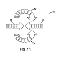
- Figure 11 is a schematic illustration of another visual interface that guides the user to achieve alignment, according to another embodiment of the present invention.
- the present invention provides a visual interface that guides the user towards a quick, accurate alignment.
- FIG. 1 illustrates projector alignment apparatus 2.
- Projector alignment apparatus 2 includes, in part, projector 4, microprocessor 5, projector lens 6, image 7, and conventional display surface 8.
- Projector 4 projects an image 7 out of projector lens 6 towards display surface 8.
- distance (dc) to the center of display surface 8
- distance (d1) to either the upper left-hand corner (A) or the distance (d2) to the lower right hand corner (B).
- passive or active distance measuring techniques can be employed.
- microprocessor 5 is utilized in order to determine what movement needs to take place to ensure proper display surface alignment and distance regiment within the system capability.
- the projection angle (f) is set by the optics design and projection settings. This angle value is utilized to compare the dc/d1 ratio to determine if the projector image 7 is skewed to the left or the right.
- the user interface will indicate to the user to rotate projector 4 in a clockwise manner. Conversely, if the ratio is larger than the expected value, the user interface will indicate to the user to rotate projector 4 in a counterclockwise manner.
- This provides a very accurate system of determining proper display surface aspect ratio/alignment without relying only on visual judgment. It is to be understood that the distance (dc) alone is utilized determine if the distance from the center of the intended projection image is within the auto focus adjustment range of the optics of projector 4. It is to be further understood that once the distance calculations have been made, the user interface will immediately provide guidance to the user on how to adjust the position and orientation of projector 4.
- a series of graphics lit by LEDs will guide the user to determine the proper distance from display surface 8 and the rotation of projector 4.
- the LEDs can be located on projector 4 and/or can be projected as part of the image upon display surface 8.
- rotation alignment is designated by a series of LEDs showing which direction to rotate ( Figures 2-5) and how far to move projector 4 towards/away from display surface 8 ( Figures 6-9). It is to be understood that the actual LED orientation can be accomplished in a number of ways, including multicolor LEDs. Also, various audio, sensory or a combination of visual, audio, and sensory indicators can be employed to accomplish the same goal.
- LED display 20 includes, in part, clockwise rotation indicators 22, 23, counterclockwise rotation indicator 24, movement towards display surface 8 indicator 26, movement away from display surface 8 indicator 28, and acceptable alignment indicator 30.
- LEDs 23 in clockwise rotation indicator 22 are illuminated in order to inform the user that projector 4 must be rotated in a clockwise direction with respect to display surface 8 in order to properly align the image 7 on display surface 8.
- LEDs 25 in counterclockwise rotation indicator 24 are illuminated in order to inform the user that projector 4 must be rotated in a counterclockwise direction with respect to display surface 8 in order to properly align the image 7 on display surface 8.
- distance indicators 26 and 28 are used to assist the user in properly determining the range of projector 4 with respect to display surface 8.
- forward distance indicator 26 includes LEDs 27. LEDs 27 in forward movement indicator 26 are illuminated in order to inform the user that projector 4 must be moved forward with respect to display surface 8 in order to properly focus the image 7 on display surface 8.
- backward distance indicator 28 includes LEDs 29. LEDs 29 in backward movement indicator 28 are illuminated in order to inform the user that projector 4 must be moved backward with respect to display surface 8 in order to properly focus the image 7 on display surface 8.
- LED display 50 includes, in part, clockwise rotation indicator 52, counterclockwise rotation indicator 54, movement towards display surface 8 indicator 56, and movement away from display surface 8 indicator 58.
- a single color LED indicator such as clockwise rotation indicator 52
- the user then rotates projector 4 in a clockwise manner with respect to display surface 8 and clockwise rotation indicator 52 will remain illuminated until projector 4 is properly rotated in the clockwise direction.
- the counterclockwise rotation indicator 54 is then selected and projector 4 is rotated in the counterclockwise direction with respect to display surface 8 until counterclockwise rotation indicator 54 becomes un-illuminated.
- the forward movement display indicator 56 is then selected and projector 4 is moved in the forward direction towards display surface 8 until forward movement display indicator 56 becomes un-illuminated.
- the backward movement display indicator 58 is selected and projector 4 is moved away from display surface 8 until backward movement display indicator 58 becomes un-illuminated.
- the present invention can be embodied in any computer-readable medium for use by or in connection with an instruction-execution system, apparatus or device such as a computer/processor based system, processor-containing system or other system that can fetch the instructions from the instruction-execution system, apparatus or device, and execute the instructions contained therein.
- a "computer-readable medium" can be any means that can store, communicate, propagate or transport a program for use by or in connection with the instruction-execution system, apparatus or device.
- the computer-readable medium can comprise any one of many physical media such as, for example, electronic, magnetic, optical, electromagnetic, infrared, or semiconductor media.
- a suitable computer-readable medium would include, but are not limited to, a portable magnetic computer diskette such as floppy diskettes or hard drives, a random access memory (RAM), a read-only memory (ROM), an erasable programmable read-only memory, or a portable compact disc.
- RAM random access memory
- ROM read-only memory
- the computer-readable medium could even be paper or another suitable medium upon which the program is printed, as the program can be electronically captured, via, for instance, optical scanning of the paper or other medium, then compiled, interpreted or otherwise processed in a single manner, if necessary, and then stored in a computer memory.
- the present invention can be implemented in hardware, software, firmware or combinations thereof. Separate embodiments of the present invention can be implemented using a combination of hardware and software or firmware that is stored in memory and executed by a suitable instruction-execution system. If implemented solely in hardware, as in an alternative embodiment, the present invention can be separately implemented with any or a combination of technologies which are well known in the art (for example, discrete-logic circuits, application-specific integrated circuits (ASICs), programmable-gate arrays (PGAs), field-programmable gate arrays (FPGAs), and/or other later developed technologies. In preferred embodiments, the present invention can be implemented in a combination of software and data executed and stored under the control of a computing device.
- ASICs application-specific integrated circuits
- PGAs programmable-gate arrays
- FPGAs field-programmable gate arrays
- the present invention can be implemented in a combination of software and data executed and stored under the control of a computing device.
Landscapes
- Engineering & Computer Science (AREA)
- Multimedia (AREA)
- Signal Processing (AREA)
- Physics & Mathematics (AREA)
- General Physics & Mathematics (AREA)
- Health & Medical Sciences (AREA)
- Biomedical Technology (AREA)
- General Health & Medical Sciences (AREA)
- Projection Apparatus (AREA)
- Automatic Focus Adjustment (AREA)
Abstract
Description
- This invention relates to a method for indicating required movement of a projector relative to a display surface, wherein the projector has an auto-focusing range, the method comprising; measuring the distance between the projector and the display surface, determining, from the measured distance and the auto focusing range, a required movement of the projector relative to the display surface, and providing feedback to indicate the required movement of the projector relative to the display surface.
- Prior to the present invention, as set forth in general terms above and more specifically below, it is known, in the projector art, to employ a projector system which automatically focuses the projector. While currently projectors are designed with auto focusing systems, the user must utilize trial and error in order to set up the projector within the allowable distance range of the optics/focusing system of the projector. Also, the user must employ his/her own visual feedback on the rotation of the image with respect to the display surface in order to achieve a rectangularly appropriate image. As can be seen, while these automatic focusing systems have met with a modicum of success, they do not provide feedback to the user to allow the user to focus/align the projector. Consequently, a more advantageous system, then, would be provided if the system provided feedback to the user to allow the user to focus/align the projector.
- It is apparent from the above that there exists a need in the projector art for a projector system that provides feedback to the user to allow the user to focus/align the projector. It is a purpose of this invention to fulfill this and other needs in the art in a manner more apparent to the skilled artisan once given the following disclosure.
- Generally speaking, an embodiment of this invention fulfills these needs by providing a method for indicating required movement of a projector relative to a display surface, wherein the projector has an auto-focusing range, the method comprising; measuring the distance between the projector and the display surface, determining, from the measured distance and the auto focusing range, a required movement of the projector relative to the display surface, and providing feedback to indicate the required movement of the projector relative to the display surface.
- In certain preferred embodiments, the feedback consists of utilizing various LED patterns to prompt the user to manually alter the screen aspect ratio/alignment of the projector.
- In another further preferred embodiment, the projector system provides an easy to use interface to quickly achieve alignment of a projector in a single try and can be used to reduce the overall optics/focusing systems range requirements.
- The preferred projector alignment system, according to various embodiment of the present invention, offers the following advantages: ease-of-use; excellent projector alignment characteristics; excellent projector range determination characteristics; good durability; and good economy. In fact, in many of the preferred embodiments, these factors of ease-of-use, excellent projector alignment characteristics, and excellent projector range determination characteristics are optimized to an extent that is considerably higher than heretofore achieved in prior, known projector alignment systems.
- The above and other features of the present invention, which will become more apparent as the description proceeds, are best understood by considering the following detailed description in conjunction with the accompanying drawings, wherein like characters represent like parts throughout the several views and in which:
- Figure 1 is a schematic illustration of a projector alignment method and user interface, according to one embodiment of the present invention;
- Figure 2 is a schematic illustration of a visual interface that guides the user to achieve clockwise alignment, according to another embodiment of the present invention;
- Figure 3 is a schematic illustration of a visual interface that guides the user to achieve further clockwise alignment, according to another embodiment of the present invention;
- Figure 4 is a schematic illustration of a visual interface that guides the user to achieve counterclockwise alignment, according to another embodiment of the present invention;
- Figure 5 is a schematic illustration of a visual interface that guides the user to achieve further counterclockwise alignment, according to another embodiment of the present invention;
- Figure 6 is a schematic illustration of a visual interface that guides the user to achieve forward alignment, according to another embodiment of the present invention;
- Figure 7 is a schematic illustration of a visual interface that guides the user to achieve further forward alignment, according to another embodiment of the present invention;
- Figure 8 is a schematic illustration of a visual interface that guides the user to achieve backward alignment, according to another embodiment of the present invention;
- Figure 9 is a schematic illustration of a visual interface that guides the user to achieve further backward alignment, according to another embodiment of the present invention;
- Figure 10 is a schematic illustration of a visual interface that informs the user that the alignment is complete, according to another embodiment of the present invention; and
- Figure 11 is a schematic illustration of another visual interface that guides the user to achieve alignment, according to another embodiment of the present invention.
- As discussed above, using a mobile projection system in many environments requires the user to determine by trial and error an appropriate distance from the display surface to allow focusing within the projector's range and rotation orientation to ensure that the projector is parallel to the display surface. To assist the user in quickly finding the optimal distance from the display surface as well as the rotation, the present invention provides a visual interface that guides the user towards a quick, accurate alignment.
- With reference first to Figure 1, there is illustrated one preferred embodiment for use of the concepts of this invention. Figure 1 illustrates
projector alignment apparatus 2.Projector alignment apparatus 2 includes, in part,projector 4, microprocessor 5,projector lens 6, image 7, and conventional display surface 8.Projector 4 projects an image 7 out ofprojector lens 6 towards display surface 8. It is to be understood that all the information necessary to guide the user to determine the proper distance and rotation can be obtained with two distance measurements referenced fromprojector 4; distance (dc) to the center of display surface 8, and distance (d1) to either the upper left-hand corner (A) or the distance (d2) to the lower right hand corner (B). It is to be further understood that passive or active distance measuring techniques can be employed. Once d1 (or d2) and dc are known, microprocessor 5 is utilized in order to determine what movement needs to take place to ensure proper display surface alignment and distance regiment within the system capability. - The projection angle (f) is set by the optics design and projection settings. This angle value is utilized to compare the dc/d1 ratio to determine if the projector image 7 is skewed to the left or the right. The relationship between the projection angle (f) and the two distances is given by the following equation (1):

- If the measured ratio is less than the expected value for the given value of dc/d 1, then the user interface will indicate to the user to rotate
projector 4 in a clockwise manner. Conversely, if the ratio is larger than the expected value, the user interface will indicate to the user to rotateprojector 4 in a counterclockwise manner. This provides a very accurate system of determining proper display surface aspect ratio/alignment without relying only on visual judgment. It is to be understood that the distance (dc) alone is utilized determine if the distance from the center of the intended projection image is within the auto focus adjustment range of the optics ofprojector 4. It is to be further understood that once the distance calculations have been made, the user interface will immediately provide guidance to the user on how to adjust the position and orientation ofprojector 4. - With respect to the user interface, a series of graphics lit by LEDs will guide the user to determine the proper distance from display surface 8 and the rotation of
projector 4. Preferably, the LEDs can be located onprojector 4 and/or can be projected as part of the image upon display surface 8. As discussed further, rotation alignment is designated by a series of LEDs showing which direction to rotate (Figures 2-5) and how far to moveprojector 4 towards/away from display surface 8 (Figures 6-9). It is to be understood that the actual LED orientation can be accomplished in a number of ways, including multicolor LEDs. Also, various audio, sensory or a combination of visual, audio, and sensory indicators can be employed to accomplish the same goal. - With respect to Figure 2, there is illustrated an
LED display 20.LED display 20 includes, in part, clockwiserotation indicators counterclockwise rotation indicator 24, movement towards display surface 8indicator 26, movement away from display surface 8indicator 28, andacceptable alignment indicator 30. As shown in Figure 2,LEDs 23 in clockwiserotation indicator 22 are illuminated in order to inform the user thatprojector 4 must be rotated in a clockwise direction with respect to display surface 8 in order to properly align the image 7 on display surface 8. - As can be seen in Figure 3,
fewer LEDs 23 are illuminated. As the user rotatesprojector 4 in a clockwise rotation towards the ideal orientation of the image 7 with respect to display surface 8,fewer LEDs 23 within clockwiserotation indicator 22 are illuminated. Once all of theLEDs 23 within clockwiserotation indicator 22 have been un-illuminated, the user can be assured thatprojector 4 has been properly aligned in the clockwise rotation with respect to display surface 8. - As shown in Figure 4,
LEDs 25 incounterclockwise rotation indicator 24 are illuminated in order to inform the user thatprojector 4 must be rotated in a counterclockwise direction with respect to display surface 8 in order to properly align the image 7 on display surface 8. - As shown in Figure 5,
fewer LEDs 25 are illuminated. As discussed above with respect to Figure 3, as the user rotatesprojector 4 in a counterclockwise rotation towards the ideal orientation of the image 7 with respect to display surface 8,fewer LEDs 25 withincounterclockwise rotation indicator 24 are illuminated. Once all of theLEDs 25 withincounterclockwise rotation indicator 24 have been un-illuminated, the user can be assured thatprojector 4 has been properly aligned in the counterclockwise rotation with respect to display surface 8. - With respect to Figure 6,
distance indicators 26 and 28 (Figures 8 and 9) are used to assist the user in properly determining the range ofprojector 4 with respect to display surface 8. As can be seen in Figure 6,forward distance indicator 26 includesLEDs 27.LEDs 27 inforward movement indicator 26 are illuminated in order to inform the user thatprojector 4 must be moved forward with respect to display surface 8 in order to properly focus the image 7 on display surface 8. - As shown in Figure 7,
fewer LEDs 27 are illuminated. As discussed above with respect to Figure 3, as the user movesprojector 4 towards display surface 8,fewer LEDs 27 withinforward movement indicator 26 are illuminated. Once all of theLEDs 27 withinforward movement indicator 26 have been un-illuminated, the user can be assured thatprojector 4 has been properly moved in a forward direction with respect to display surface 8. - With respect to Figure 8,
backward distance indicator 28 includesLEDs 29.LEDs 29 inbackward movement indicator 28 are illuminated in order to inform the user thatprojector 4 must be moved backward with respect to display surface 8 in order to properly focus the image 7 on display surface 8. - As shown in Figure 9,
fewer LEDs 29 are illuminated. As discussed above with respect to Figure 6, as the user movesprojector 4 away from display surface 8,fewer LEDs 29 withinbackward movemont indicator 28 are illuminated. Once all of theLEDs 29 withinbackward movement indicator 28 have been un-illuminated, the user can be assured thatprojector 4 has been properly moved in a backward direction with respect to display surface 8. - With respect to Figure 10, once
projector 4 has been properly aligned in the clockwise and counterclockwise directions with respect to display surface 8 andprojector 4 has properly focused the image 7 (with respect to the forward and backward distances betweenprojector 4 and display surface 8),LED 30 will become illuminated. In this manner, the user is assured thatprojector 4 is properly aligned with respect to display surface 8 and the image is properly focused on display surface 8. - With respect to Figure 11, there is illustrated another
LED display 50.LED display 50 includes, in part,clockwise rotation indicator 52,counterclockwise rotation indicator 54, movement towards display surface 8indicator 56, and movement away from display surface 8indicator 58. During the operation ofLED display 50, a single color LED indicator, such asclockwise rotation indicator 52, is selected. The user then rotatesprojector 4 in a clockwise manner with respect to display surface 8 andclockwise rotation indicator 52 will remain illuminated untilprojector 4 is properly rotated in the clockwise direction. Thecounterclockwise rotation indicator 54 is then selected andprojector 4 is rotated in the counterclockwise direction with respect to display surface 8 untilcounterclockwise rotation indicator 54 becomes un-illuminated. The forwardmovement display indicator 56 is then selected andprojector 4 is moved in the forward direction towards display surface 8 until forwardmovement display indicator 56 becomes un-illuminated. Finally, the backwardmovement display indicator 58 is selected andprojector 4 is moved away from display surface 8 until backwardmovement display indicator 58 becomes un-illuminated. - Also, the present invention can be embodied in any computer-readable medium for use by or in connection with an instruction-execution system, apparatus or device such as a computer/processor based system, processor-containing system or other system that can fetch the instructions from the instruction-execution system, apparatus or device, and execute the instructions contained therein. In the context of this disclosure, a "computer-readable medium" can be any means that can store, communicate, propagate or transport a program for use by or in connection with the instruction-execution system, apparatus or device. The computer-readable medium can comprise any one of many physical media such as, for example, electronic, magnetic, optical, electromagnetic, infrared, or semiconductor media. More specific examples of a suitable computer-readable medium would include, but are not limited to, a portable magnetic computer diskette such as floppy diskettes or hard drives, a random access memory (RAM), a read-only memory (ROM), an erasable programmable read-only memory, or a portable compact disc. It is to be understood that the computer-readable medium could even be paper or another suitable medium upon which the program is printed, as the program can be electronically captured, via, for instance, optical scanning of the paper or other medium, then compiled, interpreted or otherwise processed in a single manner, if necessary, and then stored in a computer memory.
- Those skilled in the art will understand that various embodiment of the present invention can be implemented in hardware, software, firmware or combinations thereof. Separate embodiments of the present invention can be implemented using a combination of hardware and software or firmware that is stored in memory and executed by a suitable instruction-execution system. If implemented solely in hardware, as in an alternative embodiment, the present invention can be separately implemented with any or a combination of technologies which are well known in the art (for example, discrete-logic circuits, application-specific integrated circuits (ASICs), programmable-gate arrays (PGAs), field-programmable gate arrays (FPGAs), and/or other later developed technologies. In preferred embodiments, the present invention can be implemented in a combination of software and data executed and stored under the control of a computing device.
- It will be well understood by one having ordinary skill in the art, after having become familiar with the teachings of the present invention, that software applications may be written in a number of programming languages now known or later developed.
- Once given the above disclosure, many other features, modifications or improvements will become apparent to the skilled artisan. Such features, modifications or improvements are, therefore, considered to be a part of this invention, the scope of which is to be determined by the following claims.
Claims (39)
- A method for indicating required movement of a projector (4) relative to a display surface (8), wherein the projector (4) has an auto-focusing range, the method comprising:measuring the distance (d1, d2, dc) between the projector and the display surface;determining, from the measured distance and the auto focusing range, a required movement of the projector (4) relative to the display surface (8); andproviding feedback to indicate the required movement of the projector (4) relative to the display surface (8).
- The method, as in Claim 1, wherein the measuring step is further comprised of:measuring a distance (dc) between the projector and a center of the display surface;measuring a distance (d1, d2) between the projector and at least one corner of the display surface.
- The method, as in Claim 2, wherein the determining step is further comprised of:determining a relationship between a projection angle and the measured distance between the projector (4) and the center of the display surface (8) and the distance between the projector and the at least one corner of the display surface in order to determine a proper screen aspect ratio/alignment.
- The method, as in Claim 2, wherein the determining step is further comprised of:utilizing the measured distance between the projector (4) and the center of the display surface (8) in order to determine a focal adjustment range.
- The method, as in Claim 1, wherein the providing feedback step is further comprised of: utilizing a plurality of LEDs (20) to provide Feedback to the user.
- The method, as in Claim 5, wherein the LEDs are further comprised of:at least one LED (22) that is utilized to properly Orient the projector in a clockwise manner with respect to the display surface.
- The method, as in Claim 5, wherein the LEDs are further comprised of:at least one LED (24) that is utilized to properly Orient the projector in a counterclockwise manner with respect to the display surface.
- The method, as in Claim 5, wherein the LEDs are further comprised of:at least one LED (26) that is utilized to properly locate the projector in a forward direction manner with respect to the display surface.
- The method, as in Claim 5, wherein the LEDs are further comprised of:at least one LED (28) that is utilized to properly locate the projector in a backward direction manner with respect to the display surface.
- The method, as in Claim 5, wherein the LEDs are further comprised of:at least one LED (30) that is utilized to inform the user that the projector is properly aligned with respect to the display surface.
- A projector (4) for projecting on to a display surface, comprising:a focusing system configured to automatically focus an image on the display device, while the distance between the projector (4) in the display surface (8) is within an auto-focusing range;an assessor continued to measure a distance between the projector and the display surface;a processor (5) configured to determine, from the measured distance and the auto-focusing range, a required movement of the projector relative to the display surface; anda user interface configured to provide feedback to indicate the required movement of the projector relative to the display surface.
- The projector, as in Claim 11, wherein the user Interface is further comprised of: a plurality of LEDs (20) to provide feedback to the user.
- The projector, as in Claim 12, wherein the LEDs are further comprised of:at least one LED (22) that is utilized to properly Orient the projector in a clockwise manner with respect to the display surface.
- The projector, as in Claim 12, wherein the LEDs are further comprised of:at least one LED (24) that is utilized to properly Orient the projector in a counterclockwise manner with respect to the display surface.
- The projector, as in Claim 12, wherein the LEDs are further comprised of:at least one LED (26) that is utilized to properly locate the projector in a forward direction manner with respect to the display surface.
- The projector, as in Claim 12, wherein the LEDs are further comprised of:at least one LED (28) that is utilized to properly locate the projector in a backward direction manner with respect to the display surface.
- The projector, as in Claim 12, wherein the LEDs are further comprised of:at least one LED (30) that is utilized to inform the user that the projector is properly aligned with respect to the display surface.
- The projector, as in Claim 11, wherein the user interface is further comprised of: an audio indicator to provide feedback to the user.
- The projector, as in Claim 11, wherein the user interface is further comprised of: a sensory indicator to provide feedback to the user.
- A system for projecting an to a display surface (8), the system comprising:measuring the distance (d1, d2, dc) between the projector (4) and the display surface (8);determining, from the measured distance and the auto focusing range, a required movement of the projector relative to the display surface; andproviding feedback to indicate the required movement of the projector (4) relative to the display surface (8).
- The system, as in Claim 20, wherein the measuring means is further comprised of:measuring a distance (dc) between the projector and a center of the display surface;measuring a distance (d1,d2) between the projector and at least one corner of the display surface.
- The system, as in Claim 21, wherein the determining means is further comprised of:determining a relationship between a projection angle and the measured distance between the projector and the center of the display surface and the distance between the projector and the at least one corner of the display surface in order to determine a proper screen aspect ratio/alignment.
- The system, as in Claim 21, wherein the determining means is further comprised of:utilizing the measured distance between the projector and the center of the display surface in order to determine a focal adjustment range.
- The system, as in Claim 20, wherein the feedback means is further comprised of: utilizing a plurality of LEDs (20) to provide feedback to the user.
- The system, as in Claim 24, wherein the LEDs are further comprised of:at least one LED (22) that is utilized to properly Orient the projector in a clockwise manner with respect to the display surface.
- The system, as in Claim 24, wherein the LEDs are further comprised of:at least one LED (24) that is utilized to properly Orient the projector in a counterclockwise manner with respect to the display surface.
- The system, as in Claim 24, wherein the LEDs are further comprised of:at least one LED (26) that is utilized to properly locate the projector in a forward direction manner with respect to the display surface.
- The system, as in Claim 24, wherein the LEDs are further comprised of:at least one LED (28) that is utilized to properly locate the projector in a backward direction manner with respect to the display surface.
- The System, as in Claim 24, wherein the LEDs are further comprised of:at least one LED (30) that is utilized to inform the user that the projector is properly aligned with respect to the display surface.
- A program storage System readable by a computer, tangibly embodying a program, applet, or instructions executable by the computer to perform method steps for indicating required movement of a projector relative to a display surface, wherein the projector has an auto-focusing range, the method comprising:measuring the distance (d1, d2, dc) between the projector (4) and the display surface (8); determining, from the measured distance and the auto focusing range,a required movement of the projector (4) relative to the display surface (8); and providing feedback to indicate the required movement of the projector (4) relative to the display surface (8).
- The method, as in Claim 30, wherein the measuring step is further comprised of:measuring a distance (dc) between the projector and a center of the display surface;measuring a distance (d1, d2) between the projector and at least one corner of the display surface.
- The method, as in Claim 31, wherein the determining step is further comprised of:determining a relationship between a projection angle and the measured distance between the projector (4) and the center of the display surface (8) and the distance between the projector (4) and the at least one corner of the display surface (8) in order to determine a proper screen aspect ratio/alignment.
- The method, as in Claim 31, wherein the determining step is further comprised of:utilizing the measured distance between the projector and the center of the display surface in order to determine a focal adjustment range.
- The method, as in Claim 30, wherein the providing feedback step is further comprised of: utilizing a plurality of LEDs (20) to provide feedback to the user.
- The method, as in Claim 30, wherein the LEDs are further comprised of:at least one LED (22) that is utilized to properly orient the projector in a clockwise manner with respect to the display surface.
- The method, as in Claim 30, wherein the LEDs are further comprised of:at least one LED (24) that is utilized to properly orient the projector in a counterclockwise manner with respect to the display surface.
- The method, as in Claim 34, wherein the LEDs are further comprised of:at least one LED (26) that is utilized to properly locate the projector in a forward direction manner with respect to the display surface.
- The method, as in Claim 34, wherein the LEDs are further comprised of:at least one LED (28) that is utilized to properly locate the projector in a backward direction manner with respect to the display surface.
- The method, as in Claim 34, wherein the LEDs are further comprised of:at least one LED (30) that is utilized to inform the user that the projector is properly aligned with respect to the display surface
Applications Claiming Priority (1)
| Application Number | Priority Date | Filing Date | Title |
|---|---|---|---|
| US10/971,965 US7241016B2 (en) | 2004-10-22 | 2004-10-22 | Projector alignment method and user interface |
Publications (2)
| Publication Number | Publication Date |
|---|---|
| EP1650966A2 true EP1650966A2 (en) | 2006-04-26 |
| EP1650966A3 EP1650966A3 (en) | 2008-07-23 |
Family
ID=35788838
Family Applications (1)
| Application Number | Title | Priority Date | Filing Date |
|---|---|---|---|
| EP05020784A Withdrawn EP1650966A3 (en) | 2004-10-22 | 2005-09-23 | Projector alignment method and user interface |
Country Status (4)
| Country | Link |
|---|---|
| US (1) | US7241016B2 (en) |
| EP (1) | EP1650966A3 (en) |
| JP (1) | JP2006119648A (en) |
| CN (1) | CN1763630A (en) |
Cited By (1)
| Publication number | Priority date | Publication date | Assignee | Title |
|---|---|---|---|---|
| US9762868B2 (en) | 2013-06-28 | 2017-09-12 | Thomson Licensing | Highlighting an object displayed by a pico projector |
Families Citing this family (10)
| Publication number | Priority date | Publication date | Assignee | Title |
|---|---|---|---|---|
| US20090153749A1 (en) * | 2007-12-14 | 2009-06-18 | Stephen Randall Mixon | Portable projector background color correction scheme |
| JP2010117514A (en) * | 2008-11-12 | 2010-05-27 | Seiko Epson Corp | Projector |
| JP5652596B2 (en) * | 2009-06-11 | 2015-01-14 | セイコーエプソン株式会社 | Projector, program, information storage medium, and image projection method |
| JPWO2011089684A1 (en) * | 2010-01-19 | 2013-05-20 | Necディスプレイソリューションズ株式会社 | Video display device and control method thereof |
| JP2013092542A (en) * | 2011-10-24 | 2013-05-16 | Seiko Epson Corp | Reflection type screen device |
| US20130249811A1 (en) * | 2012-03-23 | 2013-09-26 | Microsoft Corporation | Controlling a device with visible light |
| JP5999156B2 (en) * | 2014-09-25 | 2016-09-28 | セイコーエプソン株式会社 | projector |
| CN105573041A (en) * | 2014-10-09 | 2016-05-11 | 中兴通讯股份有限公司 | Method and device for realizing automatic focusing of projector, and projector |
| JP2016114956A (en) * | 2016-02-04 | 2016-06-23 | 株式会社リコー | Image projection device |
| CN109856902A (en) | 2017-11-30 | 2019-06-07 | 中强光电股份有限公司 | Projection arrangement and Atomatic focusing method |
Family Cites Families (34)
| Publication number | Priority date | Publication date | Assignee | Title |
|---|---|---|---|---|
| JPH02114250A (en) * | 1988-10-24 | 1990-04-26 | Nikon Corp | slide projector |
| JPH03141336A (en) * | 1989-10-27 | 1991-06-17 | Canon Inc | Projection type display device |
| JP2516486B2 (en) * | 1991-02-28 | 1996-07-24 | 株式会社エルモ社 | Projector |
| US5235363A (en) * | 1991-05-10 | 1993-08-10 | Nview Corporation | Method and apparatus for interacting with a computer generated projected image |
| JPH0548994A (en) * | 1991-08-19 | 1993-02-26 | Mitsubishi Electric Corp | Portable projection type projection TV |
| US5534991A (en) * | 1992-03-13 | 1996-07-09 | Canon Kabushiki Kaisha | Active distance measuring apparatus |
| US5547784A (en) * | 1993-01-18 | 1996-08-20 | Matsushita Electric Industrial Co., Ltd. | Alkaline storage battery and method for producing the same |
| US5459532A (en) * | 1993-03-29 | 1995-10-17 | Seiko Epson Corporation | Automatic focus adjuster for projection display systems having focus adjustment display symbols |
| US5386257A (en) * | 1993-09-27 | 1995-01-31 | Swartwood; Troy | Apparatus for aligning the optical system of a lamphouse and a movie projector |
| US5742358A (en) * | 1994-05-12 | 1998-04-21 | Casio Computer Co., Ltd. | Projection type displaying apparatus having screen |
| US5622417A (en) * | 1995-11-01 | 1997-04-22 | Lightware, Inc. | Invertible and orthoscopic liquid crystal display projector |
| KR100188218B1 (en) * | 1995-11-13 | 1999-06-01 | 전주범 | Asymmetric picture compensating control method for projector |
| JPH10341373A (en) * | 1997-06-06 | 1998-12-22 | Oki Electric Ind Co Ltd | Image-pickup device |
| US5847784A (en) | 1997-07-29 | 1998-12-08 | Hughes Electronics Corporation | Self adjusting tiled projector using test pattern and sensor |
| JP2000019638A (en) * | 1998-07-06 | 2000-01-21 | Nec Corp | Projector |
| JP3790064B2 (en) * | 1999-03-15 | 2006-06-28 | 株式会社東芝 | Projector device |
| US6554431B1 (en) * | 1999-06-10 | 2003-04-29 | Sony Corporation | Method and apparatus for image projection, and apparatus controlling image projection |
| JP3509652B2 (en) * | 1999-08-23 | 2004-03-22 | 日本電気株式会社 | Projector device |
| US6597410B1 (en) * | 1999-11-10 | 2003-07-22 | International Business Machines Corporation | System for the automatic adaptation of projector images and a method for the implementation thereof |
| JP3790079B2 (en) * | 1999-12-22 | 2006-06-28 | 株式会社東芝 | Projector device |
| WO2001048551A1 (en) * | 1999-12-24 | 2001-07-05 | Matsushita Electric Industrial Co., Ltd. | Projector |
| JP4242533B2 (en) * | 1999-12-27 | 2009-03-25 | オリンパス株式会社 | Bar code reader |
| US6431711B1 (en) | 2000-12-06 | 2002-08-13 | International Business Machines Corporation | Multiple-surface display projector with interactive input capability |
| JP2003029201A (en) * | 2001-07-11 | 2003-01-29 | Canon Inc | Image projection device and image correction method |
| US6785654B2 (en) * | 2001-11-30 | 2004-08-31 | Dictaphone Corporation | Distributed speech recognition system with speech recognition engines offering multiple functionalities |
| US6793351B2 (en) * | 2002-01-03 | 2004-09-21 | Eastman Kodak Company | Closed loop three color alignment system for a digital projector |
| EP1385335B1 (en) * | 2002-07-23 | 2009-04-22 | NEC Display Solutions, Ltd. | Image projector with image-feedback control |
| EP1426732A1 (en) * | 2002-11-29 | 2004-06-09 | Seiko Precision Inc. | Angle detection apparatus, projector including the same, and angle detection method |
| TW200412469A (en) * | 2003-01-02 | 2004-07-16 | Lite On Technology Corp | Automatically focusing method for projector and projector using this method |
| JP3849654B2 (en) * | 2003-02-21 | 2006-11-22 | 株式会社日立製作所 | Projection display |
| JP3844076B2 (en) * | 2003-03-07 | 2006-11-08 | セイコーエプソン株式会社 | Image processing system, projector, program, information storage medium, and image processing method |
| JP3951984B2 (en) * | 2003-08-22 | 2007-08-01 | 日本電気株式会社 | Image projection method and image projection apparatus |
| US7125122B2 (en) * | 2004-02-02 | 2006-10-24 | Sharp Laboratories Of America, Inc. | Projection system with corrective image transformation |
| JP2005227661A (en) * | 2004-02-16 | 2005-08-25 | Nec Viewtechnology Ltd | Projector and method of correcting distortion |
-
2004
- 2004-10-22 US US10/971,965 patent/US7241016B2/en not_active Expired - Fee Related
-
2005
- 2005-09-23 EP EP05020784A patent/EP1650966A3/en not_active Withdrawn
- 2005-10-20 JP JP2005305161A patent/JP2006119648A/en active Pending
- 2005-10-21 CN CN200510116488.5A patent/CN1763630A/en active Pending
Cited By (1)
| Publication number | Priority date | Publication date | Assignee | Title |
|---|---|---|---|---|
| US9762868B2 (en) | 2013-06-28 | 2017-09-12 | Thomson Licensing | Highlighting an object displayed by a pico projector |
Also Published As
| Publication number | Publication date |
|---|---|
| US20060087626A1 (en) | 2006-04-27 |
| US7241016B2 (en) | 2007-07-10 |
| JP2006119648A (en) | 2006-05-11 |
| CN1763630A (en) | 2006-04-26 |
| EP1650966A3 (en) | 2008-07-23 |
Similar Documents
| Publication | Publication Date | Title |
|---|---|---|
| US7241016B2 (en) | Projector alignment method and user interface | |
| US6310662B1 (en) | Display method and apparatus having distortion correction | |
| US7609458B2 (en) | Projection apparatus, elevation angle control method therefor and recording medium | |
| EP1517550A3 (en) | Projector with tilt angle measuring device | |
| US6433858B1 (en) | Autofocusing apparatus of a sighting telescope | |
| EP1583361A3 (en) | Image processing system, projector, information storage medium, and image processing method | |
| JP2005516716A5 (en) | ||
| EP1997585A1 (en) | Cup attaching apparatus | |
| US7258443B2 (en) | Ophthalomologic apparatus | |
| CN100412682C (en) | Projector and Zoom Adjustment Method | |
| US20080291342A1 (en) | Projection Type Video Display Apparatus | |
| EP1839948B1 (en) | Driving assistance device | |
| EP1607717A3 (en) | Position measuring system | |
| US8340371B2 (en) | Contactless biodetector | |
| EP1598687A3 (en) | Drive controller of lens apparatus | |
| JP2010149733A (en) | Head-up display | |
| US7407432B2 (en) | Lens suction jig installing apparatus and method of determining lens position using apparatus thereof | |
| US7245362B2 (en) | Lens meter | |
| JP4632826B2 (en) | Automatic mounting device for spectacle lenses | |
| JP2007155413A (en) | Lens meter | |
| EP1972982B1 (en) | Microscope equipped with automatic focusing mechanism and method of adjusting the same | |
| JPS5917108A (en) | Course guiding device | |
| US5761549A (en) | Distance measuring device for camera | |
| CN1764819A (en) | Device for visual positioning | |
| US4876568A (en) | Focusing method for printer |
Legal Events
| Date | Code | Title | Description |
|---|---|---|---|
| PUAI | Public reference made under article 153(3) epc to a published international application that has entered the european phase |
Free format text: ORIGINAL CODE: 0009012 |
|
| AK | Designated contracting states |
Kind code of ref document: A2 Designated state(s): AT BE BG CH CY CZ DE DK EE ES FI FR GB GR HU IE IS IT LI LT LU LV MC NL PL PT RO SE SI SK TR |
|
| AX | Request for extension of the european patent |
Extension state: AL BA HR MK YU |
|
| 17P | Request for examination filed |
Effective date: 20070126 |
|
| PUAL | Search report despatched |
Free format text: ORIGINAL CODE: 0009013 |
|
| AK | Designated contracting states |
Kind code of ref document: A3 Designated state(s): AT BE BG CH CY CZ DE DK EE ES FI FR GB GR HU IE IS IT LI LT LU LV MC NL PL PT RO SE SI SK TR |
|
| AX | Request for extension of the european patent |
Extension state: AL BA HR MK YU |
|
| AKX | Designation fees paid |
Designated state(s): DE FR GB |
|
| STAA | Information on the status of an ep patent application or granted ep patent |
Free format text: STATUS: THE APPLICATION IS DEEMED TO BE WITHDRAWN |
|
| 18D | Application deemed to be withdrawn |
Effective date: 20090331 |