EP1650846A1 - Power distribution network for a vehicle - Google Patents
Power distribution network for a vehicle Download PDFInfo
- Publication number
- EP1650846A1 EP1650846A1 EP05292133A EP05292133A EP1650846A1 EP 1650846 A1 EP1650846 A1 EP 1650846A1 EP 05292133 A EP05292133 A EP 05292133A EP 05292133 A EP05292133 A EP 05292133A EP 1650846 A1 EP1650846 A1 EP 1650846A1
- Authority
- EP
- European Patent Office
- Prior art keywords
- power
- connection
- station
- supplied
- stations
- Prior art date
- Legal status (The legal status is an assumption and is not a legal conclusion. Google has not performed a legal analysis and makes no representation as to the accuracy of the status listed.)
- Withdrawn
Links
- 238000000034 method Methods 0.000 claims abstract description 5
- 230000005540 biological transmission Effects 0.000 claims description 10
- 238000005259 measurement Methods 0.000 claims 1
- 230000010365 information processing Effects 0.000 description 6
- 210000000056 organ Anatomy 0.000 description 4
- 230000000694 effects Effects 0.000 description 1
- 235000021183 entrée Nutrition 0.000 description 1
Images

Classifications
-
- H—ELECTRICITY
- H02—GENERATION; CONVERSION OR DISTRIBUTION OF ELECTRIC POWER
- H02J—CIRCUIT ARRANGEMENTS OR SYSTEMS FOR SUPPLYING OR DISTRIBUTING ELECTRIC POWER; SYSTEMS FOR STORING ELECTRIC ENERGY
- H02J1/00—Circuit arrangements for dc mains or dc distribution networks
- H02J1/14—Balancing the load in a network
-
- B—PERFORMING OPERATIONS; TRANSPORTING
- B64—AIRCRAFT; AVIATION; COSMONAUTICS
- B64D—EQUIPMENT FOR FITTING IN OR TO AIRCRAFT; FLIGHT SUITS; PARACHUTES; ARRANGEMENT OR MOUNTING OF POWER PLANTS OR PROPULSION TRANSMISSIONS IN AIRCRAFT
- B64D47/00—Equipment not otherwise provided for
-
- B—PERFORMING OPERATIONS; TRANSPORTING
- B64—AIRCRAFT; AVIATION; COSMONAUTICS
- B64D—EQUIPMENT FOR FITTING IN OR TO AIRCRAFT; FLIGHT SUITS; PARACHUTES; ARRANGEMENT OR MOUNTING OF POWER PLANTS OR PROPULSION TRANSMISSIONS IN AIRCRAFT
- B64D2221/00—Electric power distribution systems onboard aircraft
-
- H—ELECTRICITY
- H02—GENERATION; CONVERSION OR DISTRIBUTION OF ELECTRIC POWER
- H02J—CIRCUIT ARRANGEMENTS OR SYSTEMS FOR SUPPLYING OR DISTRIBUTING ELECTRIC POWER; SYSTEMS FOR STORING ELECTRIC ENERGY
- H02J2310/00—The network for supplying or distributing electric power characterised by its spatial reach or by the load
- H02J2310/40—The network being an on-board power network, i.e. within a vehicle
- H02J2310/44—The network being an on-board power network, i.e. within a vehicle for aircrafts
-
- H—ELECTRICITY
- H02—GENERATION; CONVERSION OR DISTRIBUTION OF ELECTRIC POWER
- H02J—CIRCUIT ARRANGEMENTS OR SYSTEMS FOR SUPPLYING OR DISTRIBUTING ELECTRIC POWER; SYSTEMS FOR STORING ELECTRIC ENERGY
- H02J2310/00—The network for supplying or distributing electric power characterised by its spatial reach or by the load
- H02J2310/50—The network for supplying or distributing electric power characterised by its spatial reach or by the load for selectively controlling the operation of the loads
- H02J2310/56—The network for supplying or distributing electric power characterised by its spatial reach or by the load for selectively controlling the operation of the loads characterised by the condition upon which the selective controlling is based
- H02J2310/58—The condition being electrical
- H02J2310/60—Limiting power consumption in the network or in one section of the network, e.g. load shedding or peak shaving
Definitions
- Passenger transport vehicles such as airplanes, trains or coaches, are equipped with numerous electrical devices made available to passengers for their comfort.
- the vehicle seats are equipped with electric actuators for moving the various elements of the seat, and a night light is available to each passenger.
- one or more sockets for connecting personal electrical equipment, such as a laptop, are commonly available for each seat.
- each functional element disposed on the network be it an actuator, a lamp or a plug is connected to a power supply line of the vehicle via a connection station .
- the network described in this document is very complex and requires significant wiring between the different entities.
- the invention aims to provide a power distribution network for a vehicle that can have a very simple structure.
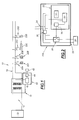
- FIG. 1 is shown an electric power distribution network 10 according to the invention.
- This network is supposed to be implanted in a vehicle and in particular in an airplane.
- the power input 12 is adapted to receive for example a current of a voltage of 115 volts and a frequency of 400 Hertz.
- a common converter 14 adapted to change the voltage and frequency of the current received from the input 12.
- This converter 14 is clean for example to output a voltage of 110 volts with a frequency of 60 Hertz or else a voltage of 220 Volts with a frequency of 50 Hertz.
- a supply line 16 formed for example of two son on which are connected in parallel a set of connection stations 20A, 20B, 20C, 20D each adapted to supply a functional body of the aircraft .
- connection stations 20A, 20B supply power to a power supply 22A, 22B allowing the connection of passenger personal equipment such as a personal computer.
- the connection station 20C supplies power to an actuator 22C while the connection station 20D supplies a lamp 22D.
- the connection stations are all identical.
- each connection station whose structure is shown in greater detail in FIG. 2 comprises an input 24 connected directly to the supply line 16 and an output 26 allowing the electrical connection of a functional element or to which is connected to remains a functional organ as in the case of the actuator 22C and the lamp 22D.
- the functional member is generally designated by reference 28 and is constituted by any type of load likely to consume electrical power.
- Each connection station comprises between the input 24 and the power supply output 26 of the functional member, means 30 for limiting the power supplied to the connected functional unit.
- these means 30 consist of controlled switching means making it possible to interrupt the power supply to the functional unit or to authorize the supply of power from the supply line 16.
- these means 30 are formed by a power limiting circuit provided to limit for example the power supplied to a predetermined value.
- these means 30 also provide a differential protection of the outlet 26.
- the means 30 are connected to a control unit 32 integrated in the connection stations.
- This unit 32 comprises communication means 33 for transmitting and receiving information between the connection station and the other network connection stations.
- these communication means 33 are connected by means of a filter adapted to the power supply line 16 and are suitable for implementing a two-way power-line communication protocol.
- the means 33 are, as known per se, adapted to effect a modulation of the information transmitted at a frequency much greater than the frequency of the electric current and to send or receive on the supply line 16 signals according to the predefined protocol.
- the control unit 32 further comprises an information processing unit 34 and a control unit 36 for controlling the power limiting means 30.
- each connection station comprises means for measuring the electrical power supplied P i to the functional unit 28 from the connection station considered.
- These means include, for example, a sensor 38 for measuring the current flowing between the input 24 and the output 26. They are connected to the information processing unit 34.
- connection stations have the same architecture and each information processing unit 34 is able to implement the algorithm of the flowchart shown in FIG. 3.
- the network 10 includes a unit 40 for defining the network with maximum available power P max .
- This unit 40 has an interface 42 for collecting this maximum available power.
- This interface is formed for example of a keyboard, or a connection interface to a central power management system of the aircraft may define a maximum power allocated to the network in question.
- the unit 40 furthermore comprises an information processing unit 44 and a powerline communication interface 46, which interface is directly connected by a filter adapted to the power supply line 16 for transmission to the various control stations. connection of information representative of the maximum available power P max .
- the power distribution network operates as follows.
- the unit 40 is clean when it is necessary to address to each distribution station 20A, 20B, 20C, 20D the same maximum available power value P max .
- This maximum available power is for example equal to 15 kW for the entire network.
- step 100 in case of reception from the unit 40 of a new maximum available power P max , the processing unit information 34 of each station stores this information.
- connection stations periodically sends on the network from their interface 33, information representative of the power supplied to the functional unit connected to the connection station.
- connection station considered receives and stores all the powers supplied P i by each of the other connection stations.
- step 104 the information processing unit 34 compares the sum of the powers supplied by all the other connection stations to the maximum available power P max .
- control means 36 act on the power limitation means 30 so that they stop feeding the functional element connected to the connection station in question or limit the power supplied to this functional unit in step 106 according to the embodiment considered.
- step 108 a new supplied power P n from the connection station in question is calculated. This is equal to 0 if the disconnection of the functional unit has been controlled or it is equal to the predetermined power P min allowed by the power limiting means 30.
- step 104 if in step 104, it is found that the sum of the powers consumed is less than the maximum available power P max , the means 30 are controlled by step 110 to allow a free consumption of power by the organ functional, however this power is limited by an individual maximum power.
- step 112 the information processing unit 34 determines from the information provided by the intensity sensor 38 the power P n actually supplied from the connection station considered.
- step 114 the power actually supplied P n is sent over the network by the interface 33 to all the other connection stations.
- each connection station knows the power actually supplied from the other connection stations and is able to limit the power it provides to the functional body connected to it so that the maximum power available P max not be exceeded.
- the network is devoid of power management unit so that its structure is very simple.
- the use of powerline transmission avoids heavy and complex wiring.
Landscapes
- Engineering & Computer Science (AREA)
- Aviation & Aerospace Engineering (AREA)
- Power Engineering (AREA)
- Remote Monitoring And Control Of Power-Distribution Networks (AREA)
- Small-Scale Networks (AREA)
Abstract
Description
La présente invention concerne un réseau de distribution de puissance électrique pour un véhicule, du type comportant :
- des postes de connexion au réseau propre chacun à fournir de la puissance à un organe fonctionnel ;
- une ligne d'alimentation sur laquelle chaque poste de connexion est connecté pour recevoir de la puissance et ;
- des moyens de limitation de la puissance fournie par les postes de connexion en fonction des puissances fournies par les différents postes de connexion, lesquels moyens de limitation comportent des moyens de mesure de la puissance fournie depuis chaque poste de connexion.
- network connection stations each clean to provide power to a functional organ;
- a power line on which each connection station is connected to receive power and;
- means for limiting the power supplied by the connection stations as a function of the powers provided by the different connection stations, which limiting means comprise means for measuring the power supplied from each connection station.
Les véhicules de transport de passagers, tel que les avions, les trains ou les autocars sont équipés de nombreux dispositifs électriques mis à la disposition des passagers pour leur confort. En particulier, il est fréquent que les sièges des véhicules soient équipés d'actionneurs électriques pour le déplacement des différents éléments du siège, et qu'une veilleuse soit mise à disposition de chaque passager. En outre, une ou plusieurs prises permettant la connexion d'un équipement électrique personnel, tel qu'un ordinateur portable sont couramment disponibles pour chaque siège.Passenger transport vehicles, such as airplanes, trains or coaches, are equipped with numerous electrical devices made available to passengers for their comfort. In particular, it is common that the vehicle seats are equipped with electric actuators for moving the various elements of the seat, and a night light is available to each passenger. In addition, one or more sockets for connecting personal electrical equipment, such as a laptop, are commonly available for each seat.
Ainsi, chaque organe fonctionnel disposé sur le réseau, qu'il s'agisse d'un actionneur, d'une lampe ou d'une prise est relié à une ligne d'alimentation du véhicule par l'intermédiaire d'un poste de connexion.Thus, each functional element disposed on the network, be it an actuator, a lamp or a plug is connected to a power supply line of the vehicle via a connection station .
Dans la mesure où la quantité de puissance électrique disponible pour l'ensemble des passagers est limitée, notamment pour des raisons de sécurité, il convient de gérer la puissance pouvant être consommée depuis chaque poste de connexion.Since the amount of electric power available to all passengers is limited, in particular for safety reasons, it is necessary to manage the power that can be consumed from each connection station.
Ainsi, il est connu de mettre en oeuvre sur le réseau, des moyens de limitation de la puissance distribuée par chaque poste de connexion en fonction de la puissance globale consommée et disponible sur le réseau.Thus, it is known to implement on the network means for limiting the power distributed by each connection station as a function of the total power consumed and available on the network.
Une telle solution est décrite par exemple dans le document EP-0 870 354 dans lequel une unité centrale de gestion de puissance est mise en oeuvre pour l'ensemble du réseau. Cette unité centrale reçoit de chaque poste de connexion une information représentative de la puissance effectivement fournie et, à partir des informations issues de chaque poste de connexion, l'unité centrale de gestion de puissance commande chaque poste de connexion pour l'autoriser ou non à fournir de la puissance supplémentaire.Such a solution is described for example in the document EP-0 870 354 in which a central power management unit is implemented for the entire network. This central unit receives from each connection station information representative of the power actually supplied and, from information from each connection station, the central power management unit controls each connection station to allow it or not to provide additional power.
Le réseau décrit dans ce document est très complexe et nécessite des câblages importants entre les différentes entités.The network described in this document is very complex and requires significant wiring between the different entities.
L'invention a pour but de proposer un réseau de distribution de puissance pour un véhicule qui puisse avoir une structure très simple.The invention aims to provide a power distribution network for a vehicle that can have a very simple structure.
A cet effet, l'invention a pour objet un réseau de distribution de puissance du type précité, caractérisé en ce que chaque poste de connexion comporte :
- des moyens d'émission, vers les autres postes de connexion du réseau, d'une information représentative de la puissance fournie depuis le poste de connexion ;
- des moyens de réception depuis chaque autre poste du réseau, de l'information émise représentative de la puissance fournie par ce poste ; et
- des moyens de commande de la puissance pouvant être fournie par le poste de connexion en fonction des informations reçues de chaque autre poste de connexion et représentatives de la puissance fournie par chaque autre poste de connexion.
- means for transmitting, to the other network connection stations, information representative of the power supplied from the connection station;
- reception means from each other station of the network, information emitted representative of the power supplied by this station; and
- means for controlling the power that can be supplied by the connection station as a function of the information received from each other connection station and representative of the power supplied by each other connection station.
Suivant des modes particuliers de réalisation, le réseau de distribution de puissance comporte l'une ou plusieurs des caractéristiques suivantes :
- les moyens d'émission et les moyens de réception comportent des moyens de transmission d'informations par courant porteur qui sont reliés à la ligne d'alimentation pour la transmission des informations représentatives de la puissance fournie sur la ligne d'alimentation ;
- il comporte pour l'ensemble des postes de connexion, un convertisseur de courant commun dont la sortie est reliée à la ligne d'alimentation et dont l'entrée est propre à être reliée à une source de puissance ;
- il comporte une unité centrale de fixation d'une puissance maximale disponible, laquelle unité comporte des moyens d'émission vers chaque poste de connexion d'une information représentative de la puissance maximale disponible, et les moyens de commande de la puissance pouvant être fournie par chaque poste de connexion comportent des moyens pour commander la puissance pouvant être fournie par le poste de connexion en fonction de l'information représentative de la puissance maximale disponible.
- au moins certains des postes de connexion comportent des prises d'alimentation permettant la connexion d'un équipement électrique indépendant.
- the transmission means and the reception means comprise power-line information transmission means which are connected to the power supply line for the transmission of information representative of the power supplied on the power supply line;
- it comprises for all connection stations, a common current converter whose output is connected to the power line and whose input is adapted to be connected to a power source;
- it includes a central unit for fixing a maximum available power, which unit comprises means for transmitting to each connection station information representative of the maximum power available, and the power control means that can be provided by each connection station comprises means for controlling the power that can be provided by the connection station according to the information representative of the maximum power available.
- at least some of the connection stations include power outlets for connecting an independent electrical equipment.
L'invention a également pour objet un procédé de distribution de puissance pour un véhicule comportant :
- des postes de connexion au réseau propre chacun à fournir de la puissance à un organe fonctionnel ;
- une ligne d'alimentation sur laquelle chaque poste de connexion est connecté pour recevoir de la puissance ;
le procédé comportant :- une mesure de la puissance fournie depuis chaque poste de connexion, et
- une limitation de la puissance fournie par les postes de connexion en fonction des puissances fournies par les différents postes de connexion,
- une émission, depuis chaque poste de connexion vers les autres postes de connexion du réseau, d'une information représentative de la puissance fournie depuis le poste de connexion ;
- une réception depuis chaque autre poste du réseau, de l'information émise représentative de la puissance fournie par chaque poste ; et
- une commande de la puissance pouvant être fournie par chaque poste de connexion en fonction des informations reçues de chaque autre poste et représentatives de la puissance fournie par chaque autre poste.
- network connection stations each clean to provide power to a functional organ;
- a power line on which each connection station is connected to receive power;
the process comprising:- a measure of the power supplied from each connection station, and
- a limitation of the power supplied by the connection stations according to the powers provided by the different connection stations,
- a transmission, from each connection station to the other network connection stations, of information representative of the power supplied from the connection station;
- a reception from each other station of the network, information emitted representative of the power provided by each station; and
- a control of the power that can be supplied by each connection station according to the information received from each other station and representative of the power supplied by each other station.
L'invention sera mieux comprise à la lecture de la description qui va suivre, donnée uniquement à titre d'exemple, et faite en se référant aux dessins sur lesquels :
- la figure 1 est une vue schématique d'un réseau de distribution de puissance selon l'invention ;
- la figure 2 est une vue schématique d'un poste de connexion du réseau de la figure 1 ; et
- la figure 3 est un organigramme de l'algorithme mis en oeuvre dans chaque poste de connexion au réseau.
- Figure 1 is a schematic view of a power distribution network according to the invention;
- Figure 2 is a schematic view of a connection station of the network of Figure 1; and
- Figure 3 is a flowchart of the algorithm implemented in each network connection station.
Sur la figure 1 est représenté un réseau de distribution de puissance électrique 10 selon l'invention. Ce réseau est supposé implanté dans un véhicule et notamment dans un avion.In Figure 1 is shown an electric
Il comporte une entrée d'alimentation de puissance 12 connectée à une source de puissance 13 telle que par exemple les génératrices de puissance électrique prévues dans les réacteurs de l'avion. Ainsi, l'entrée de puissance 12 est propre à recevoir par exemple un courant d'une tension de 115 Volts et d'une fréquence de 400 Hertz.It comprises a
En entrée du réseau, est prévu un convertisseur commun 14 propre à modifier la tension et la fréquence du courant reçues depuis l'entrée 12. Ce convertisseur 14 est propre par exemple à fournir en sortie une tension de 110 volts avec une fréquence de 60 Hertz ou encore une tension de 220 Volts avec une fréquence de 50 Hertz.At the input of the network, there is provided a
A la sortie du convertisseur 14 est reliée une ligne d'alimentation 16 formée par exemple de deux fils sur laquelle sont reliés en parallèle un ensemble de postes de connexion 20A, 20B, 20C, 20D chacun propre à alimenter un organe fonctionnel de l'avion.At the output of the
Dans l'exemple considéré, les postes de connexion 20A, 20B assurent l'alimentation d'une prise d'alimentation 22A, 22B permettant la connexion d'un équipement personnel du passager tel qu'un ordinateur personnel. Le poste de connexion 20C assure l'alimentation d'un actionneur 22C alors que le poste de connexion 20D assure l'alimentation d'une lampe 22D. Les postes de connexion sont tous identiques.In this example, the
Ainsi, chaque poste de connexion dont la structure est représentée plus en détails sur la figure 2 comporte une entrée 24 reliée directement à la ligne d'alimentation 16 et une sortie 26 permettant la liaison électrique d'un organe fonctionnel ou à laquelle est relié à demeure un organe fonctionnel comme dans le cas de l'actionneur 22C et de la lampe 22D.Thus, each connection station whose structure is shown in greater detail in FIG. 2 comprises an
Sur la figure 2, l'organe fonctionnel est désigné de manière générale par la référence 28 et est constitué par tout type de charge susceptible de consommer de la puissance électrique.In Figure 2, the functional member is generally designated by
Chaque poste de connexion comporte entre l'entrée 24 et la sortie 26 d'alimentation de l'organe fonctionnel, des moyens 30 de limitation de la puissance fournie à l'organe fonctionnel connecté.Each connection station comprises between the
Suivant un premier mode de réalisation, ces moyens 30 sont constitués de moyens de commutation commandés permettant d'interrompre la fourniture de puissance à l'organe fonctionnel ou d'autoriser la fourniture de puissance depuis la ligne d'alimentation 16. Suivant un second mode de réalisation ces moyens 30 sont formés par un circuit limiteur de la puissance fournie propre à limiter par exemple la puissance fournie à valeur prédéterminée.According to a first embodiment, these means 30 consist of controlled switching means making it possible to interrupt the power supply to the functional unit or to authorize the supply of power from the
Avantageusement, ces moyens 30 assurent en outre une protection différentielle de la sortie 26.Advantageously, these means 30 also provide a differential protection of the
Les moyens 30 sont reliés à une unité de pilotage 32 intégrée aux postes de connexion. Cette unité 32 comporte des moyens de communication 33 permettant l'émission et la réception d'informations entre le poste de connexion et les autres postes de connexion du réseau. Avantageusement, ces moyens de communication 33 sont reliés à l'aide d'un filtre adapté à la ligne d'alimentation 16 et sont propres à mettre en ceuvre un protocole de communication bidirectionnelle par courant porteur. Ainsi, les moyens 33 sont, comme connu en soi, propres à effectuer une modulation des informations transmises à une fréquence très supérieure à la fréquence du courant électrique et à envoyer ou recevoir sur la ligne d'alimentation 16 des signaux suivant le protocole prédéfini.The means 30 are connected to a
L'unité de pilotage 32 comporte en outre une unité de traitement d'informations 34 et une unité 36 de commande des moyens de limitation de puissance 30.The
Enfin, chaque poste de connexion comporte des moyens de mesure de la puissance électrique fournie Pi à l'organe fonctionnel 28 depuis le poste de connexion considéré.Finally, each connection station comprises means for measuring the electrical power supplied P i to the
Ces moyens comportent par exemple un capteur 38 de mesure de l'intensité circulant entre l'entrée 24 et la sortie 26. Ils sont reliés à l'unité de traitement d'informations 34.These means include, for example, a
Tous les postes de connexion ont la même architecture et chaque unité de traitement d'informations 34 est propre à mettre en oeuvre l'algorithme de l'organigramme est représenté sur la figure 3.All the connection stations have the same architecture and each
Par ailleurs, le réseau 10 comporte une unité 40 de définition pour le réseau d'une puissance maximale disponible Pmax. Cette unité 40 comporte une interface 42 de recueil de cette puissance maximum disponible. Cette interface est formée par exemple d'un clavier, ou d'une interface de connexion à un système central de gestion de puissance de l'avion susceptible de définir une puissance maximale allouée au réseau en cause.Furthermore, the
L'unité 40 comporte en outre une unité de traitement d'informations 44 et une interface de communication 46 par courant porteur, laquelle interface est reliée directement par un filtre adapté à la ligne d'alimentation 16 pour l'émission vers les différents postes de connexion d'une information représentative de la puissance maximale disponible Pmax.The
Le réseau de distribution de puissance fonctionne de la manière suivante.The power distribution network operates as follows.
L'unité 40 est propre lorsque cela est nécessaire à adresser à chaque poste de distribution 20A, 20B, 20C, 20D une même valeur de puissance maximale disponible Pmax. Cette puissance maximale disponible est par exemple égale à 15 kW pour l'ensemble du réseau.The
Chaque poste de connexion met en oeuvre en continu et en boucle l'algorithme de la figure 3. A l'étape 100, en cas de réception depuis l'unité 40 d'une nouvelle puissance maximale disponible Pmax, l'unité de traitement d'informations 34 de chaque poste mémorise cette information.Each connection station continuously and loops the algorithm of FIG. 3. In
Par ailleurs, l'ensemble des postes de connexion envoie périodiquement sur le réseau depuis leur interface 33, une information représentative de la puissance fournie à l'organe fonctionnel relié au poste de connexion.Furthermore, the set of connection stations periodically sends on the network from their
Ainsi, à l'étape 102, le poste de connexion considéré reçoit et mémorise l'ensemble des puissances fournies Pi par chacun des autres postes de connexion.Thus, in
A l'étape 104, l'unité de traitement d'informations 34 compare la somme des puissances fournies par l'ensemble des autres postes de connexion à la puissance maximale disponible Pmax.In
Si la somme des puissances fournies est supérieure à la puissance Pmax, les moyens de commande 36 agissent sur les moyens de limitation de la puissance 30 afin que ceux-ci cessent l'alimentation de l'organe fonctionnel relié au poste de connexion considéré ou limitent la puissance fournie à cet organe fonctionnel à l'étape 106 suivant le mode de réalisation considéré.If the sum of the powers supplied is greater than the power P max , the control means 36 act on the power limitation means 30 so that they stop feeding the functional element connected to the connection station in question or limit the power supplied to this functional unit in
A l'étape 108, une nouvelle puissance fournie Pn depuis le poste de connexion en cause est calculée. Celle-ci est égale à 0 si la déconnexion de l'organe fonctionnel a été commandée ou celle-ci est égale à la puissance prédéterminée Pmin autorisée imposée par les moyens de limitation de puissance 30.In
En revanche, si à l'étape 104, il est constaté que la somme des puissances consommées est inférieure à la puissance maximale disponible Pmax, les moyens 30 sont commandés par l'étape 110 pour autoriser une consommation libre de puissance par l'organe fonctionnel, cette puissance étant toutefois limitée par une puissance maximale individuelle.On the other hand, if in
A l'étape 112, l'unité de traitement d'informations 34 détermine à partir de l'information fournie par le capteur d'intensité 38 la puissance Pn effectivement fournie depuis le poste de connexion considéré.In
A l'étape 114, la puissance effectivement fournie Pn est envoyée sur le réseau par l'interface 33 à destination de l'ensemble des autres postes de connexion.In
Tous les postes de connexion mettent en oeuvre le même algorithme.All the connection stations implement the same algorithm.
Ainsi, avec un tel réseau, chaque poste de connexion connaît la puissance effectivement fournie depuis les autres postes de connexion et est propre à limiter la puissance qu'elle fournit à l'organe fonctionnel qui lui est connecté afin que la puissance maximale disponible Pmax ne soit pas dépassée.Thus, with such a network, each connection station knows the power actually supplied from the other connection stations and is able to limit the power it provides to the functional body connected to it so that the maximum power available P max not be exceeded.
Ainsi, le réseau est dépourvu d'unité centrale de gestion de puissance de sorte que sa structure est très simple. Par ailleurs, le recours à la transmission par courant porteur évite des câblages lourds et complexes.Thus, the network is devoid of power management unit so that its structure is very simple. In addition, the use of powerline transmission avoids heavy and complex wiring.
Claims (6)
Applications Claiming Priority (1)
| Application Number | Priority Date | Filing Date | Title |
|---|---|---|---|
| FR0411165A FR2876843B1 (en) | 2004-10-20 | 2004-10-20 | POWER DISTRIBUTION NETWORK FOR A VEHICLE |
Publications (1)
| Publication Number | Publication Date |
|---|---|
| EP1650846A1 true EP1650846A1 (en) | 2006-04-26 |
Family
ID=34950162
Family Applications (1)
| Application Number | Title | Priority Date | Filing Date |
|---|---|---|---|
| EP05292133A Withdrawn EP1650846A1 (en) | 2004-10-20 | 2005-10-12 | Power distribution network for a vehicle |
Country Status (2)
| Country | Link |
|---|---|
| EP (1) | EP1650846A1 (en) |
| FR (1) | FR2876843B1 (en) |
Cited By (11)
| Publication number | Priority date | Publication date | Assignee | Title |
|---|---|---|---|---|
| FR2911442A1 (en) * | 2007-01-16 | 2008-07-18 | Airbus France Sas | POWER SUPPLY SYSTEM AND METHOD FOR ACTUATORS ON BOARD AN AIRCRAFT |
| WO2009052305A2 (en) * | 2007-10-17 | 2009-04-23 | Be Intellectual Property, Inc. | Adaptive power management system for aircraft galleys |
| WO2010047902A3 (en) * | 2008-10-24 | 2010-08-12 | The Boeing Company | Intelligent energy management architecture |
| FR2974463A1 (en) * | 2011-04-21 | 2012-10-26 | Peugeot Citroen Automobiles Sa | Device for controlling e.g. restricted electrical power consumption mode of electrical equipment e.g. washing machine, in house, has processing unit deducing electrical power required for equipment in mode from determined electrical power |
| US8657227B1 (en) | 2009-09-11 | 2014-02-25 | The Boeing Company | Independent power generation in aircraft |
| WO2013136286A3 (en) * | 2012-03-13 | 2014-03-06 | Driessen Aerospace Group N.V. | Power management for galley with fuel cell |
| EP2725674A1 (en) | 2012-10-25 | 2014-04-30 | Ece | System for distributing electrical power to electrical outlets of a passenger vehicle |
| US8738268B2 (en) | 2011-03-10 | 2014-05-27 | The Boeing Company | Vehicle electrical power management and distribution |
| US9914548B1 (en) | 2017-02-22 | 2018-03-13 | Imagik International Corporation | USB power management and load distribution system |
| FR3074478A1 (en) * | 2017-12-01 | 2019-06-07 | Airbus Operations | ELECTRIC POWER SUPPLY LIMITATION CONTROL SYSTEM OF AN ELECTRICAL LOAD OF AN AIRCRAFT |
| EP3612910A4 (en) * | 2017-04-21 | 2021-05-19 | Ideal Industries, Inc. | Low voltage power distribution system |
Citations (5)
| Publication number | Priority date | Publication date | Assignee | Title |
|---|---|---|---|---|
| US4918690A (en) * | 1987-11-10 | 1990-04-17 | Echelon Systems Corp. | Network and intelligent cell for providing sensing, bidirectional communications and control |
| WO1998019223A1 (en) * | 1996-10-29 | 1998-05-07 | Castleman Neal J | Improved universal power-supply connection system for multiple electronic devices, and devices for use therewith |
| US5754445A (en) * | 1995-12-20 | 1998-05-19 | Primex Technologies, Inc. | Load distribution and management system |
| FR2823027A1 (en) * | 2001-03-30 | 2002-10-04 | Labinal | Installation for managing power supplied to aircraft passengers, comprises means to allocate to passenger a total power, to evaluate total power used by a passenger and to modify passenger loads |
| WO2002087053A1 (en) * | 2001-04-20 | 2002-10-31 | Jaguar Cars Limited | Motor vehicle electrical load management |
-
2004
- 2004-10-20 FR FR0411165A patent/FR2876843B1/en not_active Expired - Fee Related
-
2005
- 2005-10-12 EP EP05292133A patent/EP1650846A1/en not_active Withdrawn
Patent Citations (5)
| Publication number | Priority date | Publication date | Assignee | Title |
|---|---|---|---|---|
| US4918690A (en) * | 1987-11-10 | 1990-04-17 | Echelon Systems Corp. | Network and intelligent cell for providing sensing, bidirectional communications and control |
| US5754445A (en) * | 1995-12-20 | 1998-05-19 | Primex Technologies, Inc. | Load distribution and management system |
| WO1998019223A1 (en) * | 1996-10-29 | 1998-05-07 | Castleman Neal J | Improved universal power-supply connection system for multiple electronic devices, and devices for use therewith |
| FR2823027A1 (en) * | 2001-03-30 | 2002-10-04 | Labinal | Installation for managing power supplied to aircraft passengers, comprises means to allocate to passenger a total power, to evaluate total power used by a passenger and to modify passenger loads |
| WO2002087053A1 (en) * | 2001-04-20 | 2002-10-31 | Jaguar Cars Limited | Motor vehicle electrical load management |
Cited By (24)
| Publication number | Priority date | Publication date | Assignee | Title |
|---|---|---|---|---|
| FR2911442A1 (en) * | 2007-01-16 | 2008-07-18 | Airbus France Sas | POWER SUPPLY SYSTEM AND METHOD FOR ACTUATORS ON BOARD AN AIRCRAFT |
| US7923857B2 (en) | 2007-01-16 | 2011-04-12 | Airbus France | System and method for supplying power for actuators on board an aircraft |
| US8289670B2 (en) | 2007-10-17 | 2012-10-16 | B/E Intellectual Property | Adaptive power management system for aircraft galleys |
| WO2009052305A2 (en) * | 2007-10-17 | 2009-04-23 | Be Intellectual Property, Inc. | Adaptive power management system for aircraft galleys |
| WO2009052305A3 (en) * | 2007-10-17 | 2009-07-09 | Be Intellectual Pty Inc | Adaptive power management system for aircraft galleys |
| US8576530B2 (en) | 2007-10-17 | 2013-11-05 | B/E Intellectual Property | Adaptive power management system for aircraft galleys |
| AU2008312419B2 (en) * | 2007-10-17 | 2013-10-24 | Be Intellectual Property, Inc. | Adaptive power management system for aircraft galleys |
| CN102144344B (en) * | 2008-10-24 | 2014-02-19 | 波音公司 | Intelligent energy management architecture |
| CN102144344A (en) * | 2008-10-24 | 2011-08-03 | 波音公司 | Intelligent energy management architecture |
| US7872368B2 (en) | 2008-10-24 | 2011-01-18 | The Boeing Company | Intelligent energy management architecture |
| WO2010047902A3 (en) * | 2008-10-24 | 2010-08-12 | The Boeing Company | Intelligent energy management architecture |
| US8049360B2 (en) | 2008-10-24 | 2011-11-01 | The Boeing Company | Intelligent energy management architecture |
| US8657227B1 (en) | 2009-09-11 | 2014-02-25 | The Boeing Company | Independent power generation in aircraft |
| US8950703B2 (en) | 2009-09-11 | 2015-02-10 | The Boeing Company | Independent power generation in aircraft |
| US8738268B2 (en) | 2011-03-10 | 2014-05-27 | The Boeing Company | Vehicle electrical power management and distribution |
| FR2974463A1 (en) * | 2011-04-21 | 2012-10-26 | Peugeot Citroen Automobiles Sa | Device for controlling e.g. restricted electrical power consumption mode of electrical equipment e.g. washing machine, in house, has processing unit deducing electrical power required for equipment in mode from determined electrical power |
| WO2013136286A3 (en) * | 2012-03-13 | 2014-03-06 | Driessen Aerospace Group N.V. | Power management for galley with fuel cell |
| US9963240B2 (en) | 2012-03-13 | 2018-05-08 | Driessen Aerospace Group N.V. | Power management for galley with fuel cell |
| US20140117753A1 (en) * | 2012-10-25 | 2014-05-01 | Ece | System of distributing electric current to electrical outlets of a passenger vehicle |
| FR2997575A1 (en) * | 2012-10-25 | 2014-05-02 | Ece | SYSTEM FOR DISTRIBUTING ELECTRICAL CURRENT TO ELECTRICAL OUTLETS OF A PASSENGER TRANSPORT VEHICLE |
| EP2725674A1 (en) | 2012-10-25 | 2014-04-30 | Ece | System for distributing electrical power to electrical outlets of a passenger vehicle |
| US9914548B1 (en) | 2017-02-22 | 2018-03-13 | Imagik International Corporation | USB power management and load distribution system |
| EP3612910A4 (en) * | 2017-04-21 | 2021-05-19 | Ideal Industries, Inc. | Low voltage power distribution system |
| FR3074478A1 (en) * | 2017-12-01 | 2019-06-07 | Airbus Operations | ELECTRIC POWER SUPPLY LIMITATION CONTROL SYSTEM OF AN ELECTRICAL LOAD OF AN AIRCRAFT |
Also Published As
| Publication number | Publication date |
|---|---|
| FR2876843A1 (en) | 2006-04-21 |
| FR2876843B1 (en) | 2007-01-19 |
Similar Documents
| Publication | Publication Date | Title |
|---|---|---|
| EP1650846A1 (en) | Power distribution network for a vehicle | |
| EP0709254B1 (en) | Data communications system using carrier currents, in particular for a vehicle | |
| EP1560311B1 (en) | Power management arrangement in an aircraft | |
| EP2725674B1 (en) | System for distributing electrical power to electrical outlets of a passenger vehicle | |
| EP1582458B1 (en) | Aircraft cabin with seat actuator power management system | |
| WO2008015316A1 (en) | High availability network system | |
| EP3944982A1 (en) | Shared multipoint recharging system for electric vehicles | |
| EP3682594B1 (en) | System for managing a fibre-optic ethernet network of a vehicle | |
| FR2808630A1 (en) | MULTI-VOLTAGE ELECTRICAL SUPPLY CIRCUIT FOR MOTOR VEHICLE | |
| FR3013163A1 (en) | ELECTRIC POWER DISTRIBUTION NETWORK OF A TRANSPORT VEHICLE, SUCH AS AN AIRCRAFT, AND AN ELECTRICAL PLANT OF AN AIRCRAFT | |
| EP2073340B1 (en) | Electricity supply system for a satellite | |
| CA3064195A1 (en) | Electric power supply method and architecture for on-board domestic network | |
| CA2860286A1 (en) | Device for connecting two pieces of equipment via an ethernet link and a docking station for one of said pieces of equipment | |
| EP3179597B1 (en) | Improved device for supplying single-phase and three-phase electricity | |
| EP0970556B1 (en) | Low cost power supply device to a plurality of electronic modules installed in a compartment | |
| CA3178220A1 (en) | Distributed architecture of aircraft braking system | |
| FR3073099B1 (en) | ELECTRICAL DISTRIBUTION AND DATA CONCENTRATION BOX FOR AIRCRAFT. | |
| EP3776881B1 (en) | Data transmission device, data reception device and data transmission system | |
| EP2203913B1 (en) | Electrical device with wireless remote control and reduced consumption | |
| WO2017162946A1 (en) | Powerline communication modem, interface circuit and communication network for a motor vehicle | |
| EP1330047B1 (en) | Component for power and information distribution | |
| FR3068532A1 (en) | ELECTRICAL POWER DISTRIBUTION BOX FOR AN AIRCRAFT DRIVING NETWORK AND CORRESPONDING POWER SUPPLY SYSTEM | |
| EP3776882B1 (en) | Data transmission system | |
| EP3139485B1 (en) | Soft starting system for an electrical motor | |
| WO2007036428A1 (en) | Aircraft local multimedia network |
Legal Events
| Date | Code | Title | Description |
|---|---|---|---|
| PUAI | Public reference made under article 153(3) epc to a published international application that has entered the european phase |
Free format text: ORIGINAL CODE: 0009012 |
|
| AK | Designated contracting states |
Kind code of ref document: A1 Designated state(s): AT BE BG CH CY CZ DE DK EE ES FI FR GB GR HU IE IS IT LI LT LU LV MC NL PL PT RO SE SI SK TR |
|
| AX | Request for extension of the european patent |
Extension state: AL BA HR MK YU |
|
| RAP1 | Party data changed (applicant data changed or rights of an application transferred) |
Owner name: PRECILEC |
|
| 17P | Request for examination filed |
Effective date: 20061019 |
|
| AKX | Designation fees paid |
Designated state(s): DE FR GB IT |
|
| STAA | Information on the status of an ep patent application or granted ep patent |
Free format text: STATUS: THE APPLICATION IS DEEMED TO BE WITHDRAWN |
|
| 18D | Application deemed to be withdrawn |
Effective date: 20090505 |