EP1650832A2 - Electric connection box - Google Patents
Electric connection box Download PDFInfo
- Publication number
- EP1650832A2 EP1650832A2 EP05109912A EP05109912A EP1650832A2 EP 1650832 A2 EP1650832 A2 EP 1650832A2 EP 05109912 A EP05109912 A EP 05109912A EP 05109912 A EP05109912 A EP 05109912A EP 1650832 A2 EP1650832 A2 EP 1650832A2
- Authority
- EP
- European Patent Office
- Prior art keywords
- connectors
- case
- holding plate
- connector
- electric connection
- Prior art date
- Legal status (The legal status is an assumption and is not a legal conclusion. Google has not performed a legal analysis and makes no representation as to the accuracy of the status listed.)
- Granted
Links
- 230000007423 decrease Effects 0.000 claims description 4
- 238000009434 installation Methods 0.000 claims description 3
- XLYOFNOQVPJJNP-UHFFFAOYSA-N water Substances O XLYOFNOQVPJJNP-UHFFFAOYSA-N 0.000 description 9
- 238000003780 insertion Methods 0.000 description 3
- 230000037431 insertion Effects 0.000 description 3
- 230000008878 coupling Effects 0.000 description 2
- 238000010168 coupling process Methods 0.000 description 2
- 238000005859 coupling reaction Methods 0.000 description 2
- 238000010276 construction Methods 0.000 description 1
- 238000005192 partition Methods 0.000 description 1
Images



Classifications
-
- H—ELECTRICITY
- H01—ELECTRIC ELEMENTS
- H01R—ELECTRICALLY-CONDUCTIVE CONNECTIONS; STRUCTURAL ASSOCIATIONS OF A PLURALITY OF MUTUALLY-INSULATED ELECTRICAL CONNECTING ELEMENTS; COUPLING DEVICES; CURRENT COLLECTORS
- H01R13/00—Details of coupling devices of the kinds covered by groups H01R12/70 or H01R24/00 - H01R33/00
- H01R13/73—Means for mounting coupling parts to apparatus or structures, e.g. to a wall
-
- H—ELECTRICITY
- H01—ELECTRIC ELEMENTS
- H01R—ELECTRICALLY-CONDUCTIVE CONNECTIONS; STRUCTURAL ASSOCIATIONS OF A PLURALITY OF MUTUALLY-INSULATED ELECTRICAL CONNECTING ELEMENTS; COUPLING DEVICES; CURRENT COLLECTORS
- H01R13/00—Details of coupling devices of the kinds covered by groups H01R12/70 or H01R24/00 - H01R33/00
- H01R13/46—Bases; Cases
- H01R13/516—Means for holding or embracing insulating body, e.g. casing, hoods
- H01R13/518—Means for holding or embracing insulating body, e.g. casing, hoods for holding or embracing several coupling parts, e.g. frames
-
- H—ELECTRICITY
- H01—ELECTRIC ELEMENTS
- H01R—ELECTRICALLY-CONDUCTIVE CONNECTIONS; STRUCTURAL ASSOCIATIONS OF A PLURALITY OF MUTUALLY-INSULATED ELECTRICAL CONNECTING ELEMENTS; COUPLING DEVICES; CURRENT COLLECTORS
- H01R2201/00—Connectors or connections adapted for particular applications
- H01R2201/26—Connectors or connections adapted for particular applications for vehicles
Definitions
- This invention relates to an electric connection box in which connectors, used, for example, to join wire harnesses, are coupled together, and the coupled connectors are fixed within a case.
- this electric connection box 100 comprises a case 101, and this case 101 comprises an under case 103, and an upper case 102 attached to an upper side of the under case 103.
- Connector portions (not shown) are fixedly provided at suitable positions within the upper case 102.
- a connector fixing portion 104 comprising four retaining arms 104a, is provided within the under case 103. Harness inlet/outlet ports 105 are formed in opposed side walls of the under case 103, respectively.
- a first wire harness WH1 is divided at its end portion into two branches, and first connectors 106a and 106b are connected to ends of these branches, respectively.
- a second wire harness WH2 is divided at its end portion into three branches, and second connector 107a to 107c are connected to ends of these branches, respectively.
- the first and second wire harnesses WH1 and WH2 are passed respectively through the harness inlet/outlet ports 105 into the case 101, so that the first and second connectors 106a and 106b and 107a to 107c are introduced into the case 101.
- the first connector 106b and the second connectors 107b and 107c, introduced into the case 101, are connected respectively to the connector portions (not shown) of the upper case 102.
- One pair of first and second connectors 106a and 107a, introduced into the case 101, are coupled together, and the coupled first and second connectors 106a and 107a (hereinafter referred to as "coupled connectors") are fixed to the connector fixing portion 104.
- the first and second connectors 106b, 107b and 107c are fixed to the case 101 by fitting forces obtained by coupling these connectors to the respective connector portions (not shown).
- the coupled connectors 106a and 107a, joining the wire harnesses WH1 and WH2 are not fixed to the case 101 by coupling these connectors with each other, and therefore the coupled connectors 106a and 107a are fixed to the case 101 through the connector fixing portion 104.
- the coupled connectors 106a and 107a, joining the wire harnesses WH1 and WH2 are prevented from being moved within the case 101 by external vibrations and others.
- an object of the invention is to provide an electric connection box in which a plurality of pairs of coupled connectors can be received in a small space, and besides an operation for introducing the plurality of pairs of coupled connectors into the electric connection box, as well as an operation for removing these coupled connectors, can be carried out easily.
- the connector holding plate to which the plurality of pairs of coupled first and second connectors (hereinafter referred to as "coupled connectors") are fixed is slid along the slide rail portions, and by doing so, the plurality of pairs of coupled connectors can be fixed to the case.
- the coupled connectors and the end portions of the wire harnesses (connected to these connectors) can be taken out of the case.
- the plurality of pairs of coupled connectors can be received in a small space, and besides by sliding the connector holding plate, the plurality of pairs of coupled connectors can be simultaneously introduced into and withdrawn from the case, and therefore the operation for introducing the plurality of pairs of coupled connectors into the electric connection box, as well as the operation for removing these connectors, can be carried out easily.
- the hand of the operator can easily reach the plate locking device, and therefore the operator can easily carry out the operation for canceling the locked condition of the plate locking device.
- the wire harnesses and others will not become caught by a step formed between any two adjacent coupled connectors, and therefore this withdrawing operation is not prevented, so that the operation for withdrawing the connector holding plate can be carried out easily.
- the intrusion of water into the case can be prevented as much as possible.
- Figs. 1 to 5 show one preferred embodiment of the invention
- Fig. 1 is an exploded perspective view of an electric connection box 1
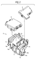
- Fig. 2 is an exploded perspective view of a case 2
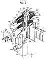
- Fig. 3 is an exploded perspective view of an important portion of the electric connection box 1
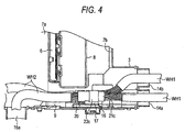
- Fig. 4 is a plan view showing a condition in which coupled connectors are received within the electric connection box
- Fig. 5 is a perspective view of a connector holding plate 17.
- the electric connection box 1 comprises the case 2 which is formed into a water-tight structure so as to prevent water from intruding into the case 2.
- the case 2 includes a case body 3 with an open top, and a first cover 4 and a second cover 5 which are attached to the case body 3 to close the open top of this case body 3.
- the interior of the case body 3 is broadly divided or partitioned into two part-receiving chambers 7a and 7b by a partition wall 6.
- Relay blocks 8 or the like are received in the two part-receiving chambers 7a and 7b, respectively.
- the two part-receiving chambers 7a and 7b communicate with each other via a communication passageway 9. Utilizing this communication passageway 9, second wire harnesses WH2 are installed over a region including the two part-receiving chambers 7a and 7b.
- harness notch grooves 10 and 11 (which are open upwardly) are formed in a side wall of the case body 3, and water stop covers 12 and 13 are slid from the upper side, and are attached respectively to the harness notch groove portions 10 and 11.
- harness inlet/outlet ports 14a, 14b, 15a and 15b for the passage of first and second wire harnesses WH1 and WH2 therethrough are formed respectively by those portions of the harness notch grooves 10 and 11 which are not closed by the water stop covers 12 and 13.
- the harness inlet/outlet ports 14a, 14b, 15a and 15b are so sized as to correspond respectively to cross-sectional areas of the first and second wire harnesses WH1 and WH2 (which are to be installed) so that water will not intrude through a gap between each of the harness inlet/outlet ports 14a, 14b, 15a and 15b and the corresponding wire harness WH1, WH2.
- a pair of slide rail portions 16 are formed on an inner surface of the side wall of the case body 3, and extend downwardly in a direction perpendicular to a direction of installation of the first and second wire harnesses WH1 and WH2, that is, extends downwardly from the vicinity of the open top (opening) of the case 2 toward the bottom of the case 2.
- the connector holding plate 17 is slidably mounted on the pair of slide rail portions 16.
- the connector holding plate 17 has a narrow elongate plate-like shape, and three connector fixing portions 18 are formed on one side (or surface) of the connector holding plate 17, and are spaced from one another in a direction of sliding of this plate 17.
- Each of the connector fixing portions 18 includes an elastic retaining portion 18a, and fitting guide plates 18b corresponding in size to each other in a right-left direction.
- Second connectors 22a, 22b and 22c (described later) are slid along the surface of the connector holding plate 17, and are fixed respectively to the corresponding connector fixing portions 18.
- the trailing-side connector and the central-side connector (with respect to the direction A of sliding insertion of the connector holding plate 17) have the same height, while the leading-side connector is smaller in height than these connectors. Namely, the three connectors are so arranged that these connectors decreases in height from the trailing side toward the leading side in the direction A of sliding insertion. Therefore, a step D is formed between the central-side second connector 22b and the leading-side second connector 22a.
- Plate locking device 20 includes an engagement portion 20a formed at that portion of the slide rail portion 16 disposed in a vicinity of the open top (opening) of the case body 3, and an elastic retaining portion 20b formed at a trailing end of the connector holding plate 17 in the sliding direction. Namely, the plate locking device 20 is provided in a vicinity of the open top (opening) of the case body 3. The plate locking device 20 locks the connector holding plate 17 against sliding movement when the connector holding plate 17 reaches a sliding-completed position.
- One or more first connectors 21a, 21b, 21c, etc. are connected to an end portion of each of the first wire harnesses WH1.
- the end portions of the first wire harnesses WH1 are passed respectively through the harness inlet/outlet ports 14a and 14b into the case 2, so that the first connectors 21a, 21b, 21c, etc., are received within the case 2.
- the three first connectors 21a, 21b and 21c for wire harness-joining purposes are coupled respectively with the second connectors 22a, 22b and 22c.
- the other first connectors (not shown) are coupled respectively with connector portions (not shown) formed integrally with the relay blocks 8 or the like.
- One or more second connectors 22a, 22b, 22c, etc. are connected to an end portion of each of the second wire harnesses WH2.
- the end portions of the second wire harnesses WH2 are passed respectively through the harness inlet/outlet ports 15a and 15b into the case 2, so that the second connectors 22a, 22b, 22c, etc., are received within the case 2.
- the three second connectors 22a, 22b and 22c have respective engagement portions (not shown) formed on their surfaces facing the connector holding plate 17, and these engagement portions are retainingly engaged respectively with the connector fixing portions 18, so that the second connectors 22a, 22b and 22c are fixed to the connector holding plate 17.
- the first connectors 21a, 21b and 21c for wire harness-joining purposes are coupled respectively with the second connectors 22a, 22b and 22c as described above.
- the other second connectors are coupled respectively with connector portions (not shown) formed integrally with the relay blocks or the like.
- the second connectors 22a, 22b and 22c are fixed to the connector fixing portions 18 of the connector holding plate 17, respectively.
- the second connectors 22a, 22b and 22c are fixed respectively in the predetermined positions on the basis of their heights as described above.
- the first connectors 21a, 21b and 21c are coupled with the second connectors 22a, 22b and 22c, respectively.
- first and second connectors are coupled respectively with the connector portions (not shown) of the relay blocks 8 or the like.
- the plurality of pairs of coupled first and second connectors 21a, 21b, 21c, 22a, 22b and 22c are fixed to the case body 3.
- the first and second wire harnesses WH1 and WH2 are located at lower portions of the harness notch grooves 10 and 11, and the water stop covers 12 and 13 are slid to be attached respectively to the harness notch grooves 10 and 11, so that the first and second wire harnesses WH1 and WH2 are disposed respectively in the harness inlet/outlet ports 14a, 14b, 15a and 15b.
- the first and second covers 4 and 5 are attached to the upper side of the case body 3.
- the first and second covers 4 and 5 are removed from the case body 3.
- the water stop covers 12 and 13 are slightly moved upwardly beyond the upper side of the case body 3, or are removed from the case body 3.
- the locked condition of the plate locking device 20 is cancelled, and the connector holding plate 17 is pulled out along the slide rail portions 16.
- the connector holding plate 17, together with the coupled connectors 21a, 21b, 21c, 22a, 22b and 22c is withdrawn from the case body 3.
- the end portions of the first and second wire harnesses WH1 and WH2 are also withdrawn.
- the three pairs of coupled connectors 21a, 21b, 21c, 22a, 22b and 22c can be received in a small space within the case 2. And besides, the operation for introducing the three pairs of coupled connectors 21a, 21b, 21c, 22a, 22b and 22c into the electric connection box, as well as the operation for removing these connectors, can be carried out easily.
- the plate locking device 20 is provided at that portion of the case body 3 disposed in a vicinity of the opening of the case body 3, and therefore the hand of the operator can easily reach the plate locking device 20, and therefore the operator can easily carry out the operation for canceling the locked condition of the plate locking device 20.
- the three pairs of coupled connectors 21a, 21b, 21c, 22a, 22b and 22c, fixed to the connector holding plate 17, are so arranged that these connectors decrease in height from the trailing side toward the leading side in the direction A of sliding insertion of the connector holding plate 17. Therefore, during the withdrawal of the connector holding plate 17, the first and second wire harnesses WH1 and WH2 and others will not become caught by the step formed between any two adjacent coupled connectors (21a, 21b, 21c, 22a, 22b and 22c), and therefore this withdrawing operation is not prevented, so that the operation for withdrawing the connector holding plate 17 can be carried out easily.
- any hole is not formed through the bottom of the case body 3, and therefore the intrusion of water into the case 2 can be prevented as much as possible.
- the number of the connector fixing portions 18 can be two or more than three.
Landscapes
- Connection Or Junction Boxes (AREA)
- Connector Housings Or Holding Contact Members (AREA)
Abstract
Description
- This invention relates to an electric connection box in which connectors, used, for example, to join wire harnesses, are coupled together, and the coupled connectors are fixed within a case.
- One conventional electric connection box of the type described is disclosed in Japanese Utility Model Publication No. JP S63-90920U, and is shown in Figs. 6 and 7. As shown in Figs. 6 and 7, this
electric connection box 100 comprises acase 101, and thiscase 101 comprises an undercase 103, and anupper case 102 attached to an upper side of the undercase 103. Connector portions (not shown) are fixedly provided at suitable positions within theupper case 102. Aconnector fixing portion 104, comprising fourretaining arms 104a, is provided within theunder case 103. Harness inlet/outlet ports 105 are formed in opposed side walls of theunder case 103, respectively. - A first wire harness WH1 is divided at its end portion into two branches, and
first connectors second connector 107a to 107c are connected to ends of these branches, respectively. - The first and second wire harnesses WH1 and WH2 are passed respectively through the harness inlet/
outlet ports 105 into thecase 101, so that the first andsecond connectors case 101. Thefirst connector 106b and thesecond connectors case 101, are connected respectively to the connector portions (not shown) of theupper case 102. One pair of first andsecond connectors case 101, are coupled together, and the coupled first andsecond connectors connector fixing portion 104. - Namely, the first and
second connectors case 101 by fitting forces obtained by coupling these connectors to the respective connector portions (not shown). However, the coupledconnectors case 101 by coupling these connectors with each other, and therefore the coupledconnectors case 101 through theconnector fixing portion 104. As a result, the coupledconnectors case 101 by external vibrations and others. - In the above conventional
electric connection box 100, however, when there are used a plurality of pairs of coupledconnectors connector fixing portions 104, corresponding in number to the plurality of pairs of coupled connectors, need to be provided within theunder cover 103, and therefore a large space need to be secured within the under cover. And besides, when there are used the plurality of coupledconnectors connector fixing portions 104, and therefore this removing operation is cumbersome. - Therefore, this invention has been made in order to solve the above problems, and an object of the invention is to provide an electric connection box in which a plurality of pairs of coupled connectors can be received in a small space, and besides an operation for introducing the plurality of pairs of coupled connectors into the electric connection box, as well as an operation for removing these coupled connectors, can be carried out easily.
- (1) The invention is directed to an electric connection box comprising:
- a case;
- first and second connectors received with in the case, which are provided at end portions of wire harnesses respectively, and which are coupled to each other;
- a slide rail portion formed on an inner surface of a wall of the case, and extending in a direction substantially perpendicular to a wire harness installation direction; and
- a connector holding plate on which at least one connector fixing portion is provided,
- wherein at least one pair of the first and second connectors coupled to each other are fixed at the connector fixing portion of the connector holding plate, which is slidably mounted into the slide rail portion.
- (2) The electric connection box of the invention may be characterized in that a plate locking device is provided in a vicinity of an opening of the case to lock the connector holding plate to the case when the connector holding plate reaches a sliding-completed position.
- (3) The electric connection box may be characterized in that plural pairs of the first and second connectors are fixed at a plurality of the connector fixing portions of the connector holding plate.
- (4) The electric connection box may be characterized in that the plural pairs of first and second connectors fixed to the connector holding plate are arranged so that heights of the pairs of the first and second connectors decrease toward a leading end of the connector holding plate.
- (5) The electric connection box of the invention may be characterized in that no hole is formed on a bottom of the case.
- In the invention, the connector holding plate to which the plurality of pairs of coupled first and second connectors (hereinafter referred to as "coupled connectors") are fixed is slid along the slide rail portions, and by doing so, the plurality of pairs of coupled connectors can be fixed to the case. By withdrawing the connector holding plate along the slide rail portions, the coupled connectors and the end portions of the wire harnesses (connected to these connectors) can be taken out of the case. With this construction, the plurality of pairs of coupled connectors can be received in a small space, and besides by sliding the connector holding plate, the plurality of pairs of coupled connectors can be simultaneously introduced into and withdrawn from the case, and therefore the operation for introducing the plurality of pairs of coupled connectors into the electric connection box, as well as the operation for removing these connectors, can be carried out easily.
- In the invention, the hand of the operator can easily reach the plate locking device, and therefore the operator can easily carry out the operation for canceling the locked condition of the plate locking device.
- In the invention, during the withdrawal of the connector holding plate, the wire harnesses and others will not become caught by a step formed between any two adjacent coupled connectors, and therefore this withdrawing operation is not prevented, so that the operation for withdrawing the connector holding plate can be carried out easily.
- In the invention, the intrusion of water into the case can be prevented as much as possible.
-
- Fig. 1 is an exploded perspective view of one preferred embodiment of an electric connection box of the present invention;
- Fig. 2 is an exploded perspective view of a case of the electric connection box;
- Fig. 3 is an exploded perspective view of an important portion of the electric connection box;
- Fig. 4 is a plan view showing a condition in which connectors are received within the electric connection box;
- Fig. 5 is a perspective view of a connector holding plate;
- Fig. 6 is an exploded perspective view of a conventional electric connection box; and
- Fig. 7 is a cross-sectional view of the conventional electric connection box.
- One preferred embodiment of the present invention will now be described with reference to the drawings.
- Figs. 1 to 5 show one preferred embodiment of the invention, and Fig. 1 is an exploded perspective view of an electric connection box 1, Fig. 2 is an exploded perspective view of a
case 2, Fig. 3 is an exploded perspective view of an important portion of the electric connection box 1, Fig. 4 is a plan view showing a condition in which coupled connectors are received within the electric connection box, and Fig. 5 is a perspective view of aconnector holding plate 17. - As shown in Figs. 1 and 2, the electric connection box 1 comprises the
case 2 which is formed into a water-tight structure so as to prevent water from intruding into thecase 2. Thecase 2 includes acase body 3 with an open top, and afirst cover 4 and asecond cover 5 which are attached to thecase body 3 to close the open top of thiscase body 3. - The interior of the
case body 3 is broadly divided or partitioned into two part-receiving chambers partition wall 6.Relay blocks 8 or the like are received in the two part-receivingchambers receiving chambers communication passageway 9. Utilizing thiscommunication passageway 9, second wire harnesses WH2 are installed over a region including the two part-receiving chambers - Two
harness notch grooves 10 and 11 (which are open upwardly) are formed in a side wall of thecase body 3, and water stop covers 12 and 13 are slid from the upper side, and are attached respectively to the harnessnotch groove portions outlet ports harness notch grooves outlet ports outlet ports - As shown in detail in Figs. 3 and 4, a pair of
slide rail portions 16 are formed on an inner surface of the side wall of thecase body 3, and extend downwardly in a direction perpendicular to a direction of installation of the first and second wire harnesses WH1 and WH2, that is, extends downwardly from the vicinity of the open top (opening) of thecase 2 toward the bottom of thecase 2. Theconnector holding plate 17 is slidably mounted on the pair ofslide rail portions 16. - As shown in detail in Figs. 3 to 5, the
connector holding plate 17 has a narrow elongate plate-like shape, and three connector fixing portions 18 are formed on one side (or surface) of theconnector holding plate 17, and are spaced from one another in a direction of sliding of thisplate 17. Each of the connector fixing portions 18 includes anelastic retaining portion 18a, andfitting guide plates 18b corresponding in size to each other in a right-left direction.Second connectors connector holding plate 17, and are fixed respectively to the corresponding connector fixing portions 18. With respect to the threesecond connectors connector holding plate 17, the trailing-side connector and the central-side connector (with respect to the direction A of sliding insertion of the connector holding plate 17) have the same height, while the leading-side connector is smaller in height than these connectors. Namely, the three connectors are so arranged that these connectors decreases in height from the trailing side toward the leading side in the direction A of sliding insertion. Therefore, a step D is formed between the central-sidesecond connector 22b and the leading-sidesecond connector 22a. -
Plate locking device 20 includes anengagement portion 20a formed at that portion of theslide rail portion 16 disposed in a vicinity of the open top (opening) of thecase body 3, and anelastic retaining portion 20b formed at a trailing end of theconnector holding plate 17 in the sliding direction. Namely, theplate locking device 20 is provided in a vicinity of the open top (opening) of thecase body 3. Theplate locking device 20 locks theconnector holding plate 17 against sliding movement when theconnector holding plate 17 reaches a sliding-completed position. - Any hole is not formed through the bottom of the
case body 3. - One or more
first connectors outlet ports case 2, so that thefirst connectors case 2. Among the first connectors received within thecase 2, the threefirst connectors second connectors - One or more
second connectors outlet ports case 2, so that thesecond connectors case 2. Among the second connectors received within thecase 2, the threesecond connectors connector holding plate 17, and these engagement portions are retainingly engaged respectively with the connector fixing portions 18, so that thesecond connectors connector holding plate 17. Thefirst connectors second connectors - Next, an operation for introducing the first and
second connectors second connectors - First, the
second connectors connector holding plate 17, respectively. At this time, thesecond connectors first connectors second connectors - Then, the leading end of the
connector holding plate 17 is engaged with upper ends of theslide rail portions 16, and in this condition theconnector holding plate 17 is slid along theslide rail portions 16, and is inserted toward the bottom of thecase body 3. Then, theconnector holding plate 17 is locked by theplate locking device 20, thus completing this operation. The other first and second connectors (not shown) are coupled respectively with the connector portions (not shown) of the relay blocks 8 or the like. - Thus, the plurality of pairs of coupled first and
second connectors case body 3. After this connector fixing operation, the first and second wire harnesses WH1 and WH2 are located at lower portions of theharness notch grooves harness notch grooves outlet ports second covers case body 3. - For removing the coupled
connectors second covers case body 3. Then, the water stop covers 12 and 13 are slightly moved upwardly beyond the upper side of thecase body 3, or are removed from thecase body 3. Then, the locked condition of theplate locking device 20 is cancelled, and theconnector holding plate 17 is pulled out along theslide rail portions 16. As a result, theconnector holding plate 17, together with the coupledconnectors case body 3. Similarly, the end portions of the first and second wire harnesses WH1 and WH2 are also withdrawn. As described above, the three pairs of coupledconnectors case 2. And besides, the operation for introducing the three pairs of coupledconnectors - In this embodiment, the
plate locking device 20 is provided at that portion of thecase body 3 disposed in a vicinity of the opening of thecase body 3, and therefore the hand of the operator can easily reach theplate locking device 20, and therefore the operator can easily carry out the operation for canceling the locked condition of theplate locking device 20. - In this embodiment, the three pairs of coupled
connectors connector holding plate 17, are so arranged that these connectors decrease in height from the trailing side toward the leading side in the direction A of sliding insertion of theconnector holding plate 17. Therefore, during the withdrawal of theconnector holding plate 17, the first and second wire harnesses WH1 and WH2 and others will not become caught by the step formed between any two adjacent coupled connectors (21a, 21b, 21c, 22a, 22b and 22c), and therefore this withdrawing operation is not prevented, so that the operation for withdrawing theconnector holding plate 17 can be carried out easily. - In this embodiment, any hole is not formed through the bottom of the
case body 3, and therefore the intrusion of water into thecase 2 can be prevented as much as possible. - In the above embodiment, although the three connector fixing portions 18 are formed on the
connector holding plate 17, the number of the connector fixing portions 18 can be two or more than three.
Claims (5)
- An electric connection box comprising:a case;first and second connectors received with in the case, which are provided at end portions of wire harnesses respectively, and which are coupled to each other;a slide rail portion formed on an inner surface of a wall of said case, and extending in a direction substantially perpendicular to a wire harness installation direction; anda connector holding plate on which at least one connector fixing portion is provided,wherein at least one pair of said first and second connectors coupled to each other are fixed at said connector fixing portion of said connector holding plate, which is slidably mounted into said slide rail portion.
- An electric connection box according to claim 1, wherein a plate locking device is provided in a vicinity of an opening of said case to lock said connector holding plate to said case when said connector holding plate reaches a sliding-completed position.
- An electric connection box according to claim 1, wherein a plural pairs of said first and second connectors are fixed at a plurality of the connector fixing portions of said connector holding plate.
- An electric connection box according to claim 3, wherein said plural pairs of first and second connectors fixed to said connector holding plate are arranged so that heights of said pairs of said first and second connectors decrease toward a leading end of said connector holding plate.
- An electric connection box according to claim 1, wherein no hole is formed on a bottom of said case.
Applications Claiming Priority (1)
| Application Number | Priority Date | Filing Date | Title |
|---|---|---|---|
| JP2004310111A JP4253632B2 (en) | 2004-10-25 | 2004-10-25 | Electrical junction box |
Publications (3)
| Publication Number | Publication Date |
|---|---|
| EP1650832A2 true EP1650832A2 (en) | 2006-04-26 |
| EP1650832A3 EP1650832A3 (en) | 2007-05-02 |
| EP1650832B1 EP1650832B1 (en) | 2011-07-27 |
Family
ID=35589540
Family Applications (1)
| Application Number | Title | Priority Date | Filing Date |
|---|---|---|---|
| EP05109912A Ceased EP1650832B1 (en) | 2004-10-25 | 2005-10-24 | Electric connection box |
Country Status (3)
| Country | Link |
|---|---|
| US (1) | US7122738B2 (en) |
| EP (1) | EP1650832B1 (en) |
| JP (1) | JP4253632B2 (en) |
Families Citing this family (22)
| Publication number | Priority date | Publication date | Assignee | Title |
|---|---|---|---|---|
| WO2008154028A1 (en) * | 2007-06-11 | 2008-12-18 | Byrne Norman R | Wire management system for modular electrical systems |
| US8819743B2 (en) | 2007-12-19 | 2014-08-26 | Dish Network L.L.C. | Transfer of data related to broadcast programming over a communication network |
| US7572976B1 (en) * | 2008-02-06 | 2009-08-11 | Victor Merrill | Quick connect electrical box |
| US8907862B2 (en) | 2011-04-12 | 2014-12-09 | Dish Network L.L.C. | Apparatus and systems for mounting an electrical switching device |
| US9337545B2 (en) | 2008-06-20 | 2016-05-10 | Dish Network L.L.C. | Apparatus and systems for mounting an electrical switching device |
| US8113874B2 (en) * | 2009-11-30 | 2012-02-14 | Copper Technologies Company | External quick connect modular plug for a wiring device |
| US8235748B2 (en) * | 2009-11-30 | 2012-08-07 | Cooper Technologies Company | External quick connect modular plug for a wiring device |
| JP5514528B2 (en) * | 2009-12-14 | 2014-06-04 | 矢崎総業株式会社 | Electrical junction box |
| US8462075B2 (en) | 2010-02-23 | 2013-06-11 | Dish Network L.L.C. | Apparatus for mounting an object to a railing |
| US8981220B2 (en) * | 2010-05-27 | 2015-03-17 | Qwest Communications International Inc. | Universal cable adapter |
| JP5608470B2 (en) * | 2010-08-23 | 2014-10-15 | 矢崎総業株式会社 | Electrical junction box |
| US8646186B2 (en) | 2010-12-16 | 2014-02-11 | Dish Network L.L.C. | Multi-angle levels and plumbing methods |
| US8802985B2 (en) * | 2011-09-07 | 2014-08-12 | Dish Network L.L.C. | In-wall extension apparatus |
| JP5881211B2 (en) * | 2012-04-02 | 2016-03-09 | 矢崎総業株式会社 | Wire harness wiring structure |
| US9123987B2 (en) | 2012-07-31 | 2015-09-01 | Dish Network L.L.C. | Antenna mounting systems and methods |
| JP5705812B2 (en) * | 2012-11-15 | 2015-04-22 | 古河電気工業株式会社 | Connector holder |
| JP6157960B2 (en) * | 2013-07-16 | 2017-07-05 | 矢崎総業株式会社 | Electrical junction box |
| US10103475B1 (en) | 2013-12-09 | 2018-10-16 | VCE IP Holding Company LLC | Optimized shipping of IP telephony devices |
| JP6810893B2 (en) * | 2017-06-14 | 2021-01-13 | 株式会社オートネットワーク技術研究所 | Wiring unit |
| US11623590B2 (en) | 2021-01-08 | 2023-04-11 | Lear Corporation | Electrical connector cover |
| JP7410103B2 (en) * | 2021-09-24 | 2024-01-09 | 矢崎総業株式会社 | wire harness |
| JP7602518B2 (en) * | 2022-09-21 | 2024-12-18 | 矢崎総業株式会社 | Wire Harness |
Citations (1)
| Publication number | Priority date | Publication date | Assignee | Title |
|---|---|---|---|---|
| JPS6390920U (en) | 1986-11-28 | 1988-06-13 |
Family Cites Families (14)
| Publication number | Priority date | Publication date | Assignee | Title |
|---|---|---|---|---|
| JPS55129384A (en) | 1978-12-29 | 1980-10-07 | Matsushita Electric Industrial Co Ltd | Vertical synchronization circuit for image tube display monitor |
| JPS5865781A (en) | 1981-09-10 | 1983-04-19 | Nec Corp | Liquid crystal substance and liquid crystal display element |
| JPS61103871A (en) | 1984-10-29 | 1986-05-22 | Nippon Steel Chem Co Ltd | Method for producing 5,6,7,8-tetrahydroisoquinoline |
| US4593960A (en) * | 1985-03-27 | 1986-06-10 | Amp Incorporated | Power entry connector |
| JPS6390920A (en) | 1986-10-06 | 1988-04-21 | Canon Inc | Galois field dividing circuit |
| KR890011148A (en) * | 1987-12-15 | 1989-08-12 | 구메 다다시 | Electrical connectors prevent incomplete mating |
| US5087757A (en) | 1987-12-16 | 1992-02-11 | The Dow Chemical Company | Preparation of alkylthioethylamine salts |
| DE19546952C2 (en) * | 1994-12-17 | 1999-06-17 | Horiba Ltd | Gas analyzer rack assembly |
| JPH08289439A (en) * | 1995-04-17 | 1996-11-01 | Yazaki Corp | Waterproof box for fixing connectors |
| US5664955A (en) * | 1995-09-26 | 1997-09-09 | Lucent Technologies Inc. | Protective hood |
| JP3287535B2 (en) * | 1996-07-22 | 2002-06-04 | 矢崎総業株式会社 | Connector mounting structure |
| JP3341820B2 (en) * | 1997-10-17 | 2002-11-05 | 矢崎総業株式会社 | Coupling type connector |
| JP2004312793A (en) * | 2003-04-02 | 2004-11-04 | Yazaki Corp | Electrical junction box and method of assembling the same |
| DE102004026569B4 (en) * | 2003-05-30 | 2011-02-10 | Sumitomo Wiring Systems, Ltd., Yokkaichi-shi | Connector support structure and clamped degree calculation method |
-
2004
- 2004-10-25 JP JP2004310111A patent/JP4253632B2/en not_active Expired - Fee Related
-
2005
- 2005-10-24 EP EP05109912A patent/EP1650832B1/en not_active Ceased
- 2005-10-25 US US11/257,100 patent/US7122738B2/en not_active Expired - Lifetime
Patent Citations (1)
| Publication number | Priority date | Publication date | Assignee | Title |
|---|---|---|---|---|
| JPS6390920U (en) | 1986-11-28 | 1988-06-13 |
Also Published As
| Publication number | Publication date |
|---|---|
| US7122738B2 (en) | 2006-10-17 |
| EP1650832A3 (en) | 2007-05-02 |
| JP4253632B2 (en) | 2009-04-15 |
| EP1650832B1 (en) | 2011-07-27 |
| US20060089029A1 (en) | 2006-04-27 |
| JP2006121878A (en) | 2006-05-11 |
Similar Documents
| Publication | Publication Date | Title |
|---|---|---|
| EP1650832B1 (en) | Electric connection box | |
| US5725397A (en) | Divisional type connector | |
| CN110581467B (en) | Locking structure, electrical connection box and wire harness | |
| US7559779B1 (en) | Electrical connector | |
| US7195515B2 (en) | Wire harness leading-out structure | |
| EP1303009B1 (en) | A cover, a joint connector and a method for mounting a joint connector | |
| CN108604758B (en) | Connector | |
| DE102004016152B4 (en) | Electrical connection box and method for assembling an electrical connection box | |
| CN104648279A (en) | Obd connector protective cover | |
| JP6836889B2 (en) | Electrical junction box and wire harness | |
| EP3766740B1 (en) | Protector and wire harness | |
| US10720718B2 (en) | Branch connector and communication network | |
| JP4058889B2 (en) | connector | |
| KR100659184B1 (en) | Joint connector | |
| EP0945928B1 (en) | Connector fitting structure | |
| KR101930622B1 (en) | Cover box for wire extraction, floor panel and panel assembly comprising the same | |
| DE102020131739A1 (en) | DUST COVER FOR AN ELECTRICAL CONNECTOR IN AN ELECTRONIC CONTROL UNIT (ECU) ASSEMBLY | |
| US6203351B1 (en) | Connector locking structure | |
| JP5075537B2 (en) | Cover mounting structure, connector, and cover | |
| US6676453B1 (en) | Locking element for electrical connector assembly | |
| JP7810574B2 (en) | Electrical junction box | |
| EP1420494B1 (en) | Electric mechanism adapter for surface installations | |
| EP4641751A1 (en) | Battery pack and electronic device | |
| US6857885B2 (en) | Cable from connector comprising a compact locking element in a vibration-proof and water-tight design | |
| CN216720721U (en) | Power distribution control cabinet |
Legal Events
| Date | Code | Title | Description |
|---|---|---|---|
| PUAI | Public reference made under article 153(3) epc to a published international application that has entered the european phase |
Free format text: ORIGINAL CODE: 0009012 |
|
| AK | Designated contracting states |
Kind code of ref document: A2 Designated state(s): AT BE BG CH CY CZ DE DK EE ES FI FR GB GR HU IE IS IT LI LT LU LV MC NL PL PT RO SE SI SK TR |
|
| AX | Request for extension of the european patent |
Extension state: AL BA HR MK YU |
|
| PUAL | Search report despatched |
Free format text: ORIGINAL CODE: 0009013 |
|
| AK | Designated contracting states |
Kind code of ref document: A3 Designated state(s): AT BE BG CH CY CZ DE DK EE ES FI FR GB GR HU IE IS IT LI LT LU LV MC NL PL PT RO SE SI SK TR |
|
| AX | Request for extension of the european patent |
Extension state: AL BA HR MK YU |
|
| RIC1 | Information provided on ipc code assigned before grant |
Ipc: H01R 13/73 20060101AFI20070329BHEP Ipc: H01R 13/518 20060101ALI20070329BHEP |
|
| RAP1 | Party data changed (applicant data changed or rights of an application transferred) |
Owner name: YAZAKI CORPORATION |
|
| 17P | Request for examination filed |
Effective date: 20071022 |
|
| AKX | Designation fees paid |
Designated state(s): DE FR GB |
|
| GRAP | Despatch of communication of intention to grant a patent |
Free format text: ORIGINAL CODE: EPIDOSNIGR1 |
|
| GRAS | Grant fee paid |
Free format text: ORIGINAL CODE: EPIDOSNIGR3 |
|
| GRAA | (expected) grant |
Free format text: ORIGINAL CODE: 0009210 |
|
| AK | Designated contracting states |
Kind code of ref document: B1 Designated state(s): DE FR GB |
|
| REG | Reference to a national code |
Ref country code: GB Ref legal event code: FG4D |
|
| REG | Reference to a national code |
Ref country code: DE Ref legal event code: R096 Ref document number: 602005029162 Country of ref document: DE Effective date: 20110915 |
|
| PLBE | No opposition filed within time limit |
Free format text: ORIGINAL CODE: 0009261 |
|
| STAA | Information on the status of an ep patent application or granted ep patent |
Free format text: STATUS: NO OPPOSITION FILED WITHIN TIME LIMIT |
|
| 26N | No opposition filed |
Effective date: 20120502 |
|
| REG | Reference to a national code |
Ref country code: DE Ref legal event code: R097 Ref document number: 602005029162 Country of ref document: DE Effective date: 20120502 |
|
| REG | Reference to a national code |
Ref country code: FR Ref legal event code: PLFP Year of fee payment: 12 |
|
| REG | Reference to a national code |
Ref country code: FR Ref legal event code: PLFP Year of fee payment: 13 |
|
| REG | Reference to a national code |
Ref country code: FR Ref legal event code: PLFP Year of fee payment: 14 |
|
| PGFP | Annual fee paid to national office [announced via postgrant information from national office to epo] |
Ref country code: FR Payment date: 20200914 Year of fee payment: 16 |
|
| PGFP | Annual fee paid to national office [announced via postgrant information from national office to epo] |
Ref country code: GB Payment date: 20201014 Year of fee payment: 16 Ref country code: DE Payment date: 20201013 Year of fee payment: 16 |
|
| REG | Reference to a national code |
Ref country code: DE Ref legal event code: R119 Ref document number: 602005029162 Country of ref document: DE |
|
| GBPC | Gb: european patent ceased through non-payment of renewal fee |
Effective date: 20211024 |
|
| PG25 | Lapsed in a contracting state [announced via postgrant information from national office to epo] |
Ref country code: GB Free format text: LAPSE BECAUSE OF NON-PAYMENT OF DUE FEES Effective date: 20211024 Ref country code: DE Free format text: LAPSE BECAUSE OF NON-PAYMENT OF DUE FEES Effective date: 20220503 |
|
| PG25 | Lapsed in a contracting state [announced via postgrant information from national office to epo] |
Ref country code: FR Free format text: LAPSE BECAUSE OF NON-PAYMENT OF DUE FEES Effective date: 20211031 |