EP1650623A1 - Method for managing machine tool data - Google Patents
Method for managing machine tool data Download PDFInfo
- Publication number
- EP1650623A1 EP1650623A1 EP05109130A EP05109130A EP1650623A1 EP 1650623 A1 EP1650623 A1 EP 1650623A1 EP 05109130 A EP05109130 A EP 05109130A EP 05109130 A EP05109130 A EP 05109130A EP 1650623 A1 EP1650623 A1 EP 1650623A1
- Authority
- EP
- European Patent Office
- Prior art keywords
- machining
- machining operation
- machine tool
- data
- cycle
- Prior art date
- Legal status (The legal status is an assumption and is not a legal conclusion. Google has not performed a legal analysis and makes no representation as to the accuracy of the status listed.)
- Ceased
Links
Images




Classifications
-
- G—PHYSICS
- G05—CONTROLLING; REGULATING
- G05B—CONTROL OR REGULATING SYSTEMS IN GENERAL; FUNCTIONAL ELEMENTS OF SUCH SYSTEMS; MONITORING OR TESTING ARRANGEMENTS FOR SUCH SYSTEMS OR ELEMENTS
- G05B19/00—Program-control systems
- G05B19/02—Program-control systems electric
- G05B19/18—Numerical control [NC], i.e. automatically operating machines, in particular machine tools, e.g. in a manufacturing environment, so as to execute positioning, movement or co-ordinated operations by means of program data in numerical form
- G05B19/406—Numerical control [NC], i.e. automatically operating machines, in particular machine tools, e.g. in a manufacturing environment, so as to execute positioning, movement or co-ordinated operations by means of program data in numerical form characterised by monitoring or safety
- G05B19/4065—Monitoring tool breakage, life or condition
Definitions
- the present invention relates to a method for managing machine tool data.
- Such systems may include a scheduled tool change based on a number of parts produced, or scheduled machine down time, during which bearings and other components may be replaced prior to their having an adverse effect on product quality.
- decision-makers need information.
- information that is indicative of historical trends is useful, so that accurate predictions can be made regarding future production runs.
- the ability to isolate particular problem areas is also useful; this helps to concentrate efforts where they will have the most impact and produce the most benefit.
- vibration analysis Information gathered from this type of analysis may be indicative of a variety of different production problems.
- a machine tool during non-machining operations, may see vibrations which are many times higher than those seen during a cutting operation, it may be desirable to isolate non-machining data for separate evaluation from the machining data. This data could then be used as an indicator of the health of the machine tool itself, rather than indicating the health of a particular machining process.
- the present invention provides a method for managing machine tool data that isolates non-machining data from machining data, thereby providing an indicator of the health of the machine tool.
- the invention also provides a method for managing machine tool data, where the machine tool is operable to perform at least one operation cycle which includes at least one machining operation and at least one non-machining operation.
- the machine tool has at least one sensor operatively connected thereto for sensing a machine operation parameter, and further has a controller configured to output data related to the at least one operation cycle.
- the method includes operating the machine tool to perform at least a portion of an operation cycle which includes a non-machining operation.
- Data from signals output from the at least one sensor and from the controller are processed to define a non-machining operation-specific data profile for the non-machining operation.
- An algorithm is applied to the non-machining operation-specific data profile to generate a non-machining operation-specific data point. This facilitates generation of a non-machining operation-specific trend line.
- a method for managing machine tool data for a machine tool that is operable to perform at least one operation cycle, including at least one machining operation and at least one non-machining operation.
- the machine tool has at least one sensor operatively connected thereto for sensing a machine operation parameter.
- the machine tool also has a controller configured to output data related to the at least one operation cycle.
- the method includes sensing a machine operation parameter for the machine tool for at least a portion of at least one operation cycle including a plurality of non-machining operations.
- Data related to the sensed parameter is stored, as is data from signals output from the controller.
- the data from the sensor is associated with the data from the controller, which facilitates defining corresponding non-machining operation-specific data profiles for at least some of the non-machining operations.
- An algorithm is applied to at least some of the non-machining operation-specific data profiles to generate corresponding non-machining operation-specific data points.
- the non-machining operation-specific data points are stored, which facilities their subsequent retrieval.
- a method for managing machine tool data where the machine tool has a controller operatively connected thereto for outputting data related to operation of the machine tool.
- the method includes performing at least one machining operation, and performing at least one non-machining operation.
- a machine operation parameter for the machine tool is sensed when it is performing the at least one machining operation and the at least one non-machining operation.
- the sensed machine operation parameter is associated with data output from the controller, which facilitates defining corresponding machining operation-specific data profiles and non-machining operation-specific data profiles.
- An algorithm is applied to at least some of the associated data to generate corresponding machining operation-specific data points and non-machining operation-specific data points, which facilitates generation of machining operation-specific trend lines and non-machining operation-specific trend lines.
- FIG 1 illustrates a data management system 10 for a machine tool 11.
- the machine tool 11 includes a bed 12 and a spindle 14.
- the machine tool 11, shown in Figure 1, is a computer numerical control (CNC) milling machine.
- CNC computer numerical control
- the present invention can be used with virtually any type of machine tool, including manual as well as CNC machines.
- a cutting tool 16 which is used to machine a workpiece 18.
- a vibration sensor 20 Attached to the spindle 14 is a vibration sensor 20 that is configured to sense vibrations in the spindle 14 and output signals related to the vibrations to a processing unit 22.
- the vibration sensor 20 may be chosen from any one of a number of types of vibration sensors, such as an accelerometer, a velocity sensor, or any other suitable sensor capable of sensing vibrations.
- a current sensor may be used to measure changes in the amount of current the machine tool 11 draws during various operations.
- a thermocouple or other type of temperature sensor, could be used to detect changes in temperature of some portion of the machine tool 11. The spindle speed, torque, or feed rate could also be sensed to provide information relating to the operations.
- any sensor capable of sensing a machine operation parameter can be used to send signals to the processing unit 22.
- the processing unit 22 may be conveniently mounted directly on a portion of the machine tool 11, and includes a processor 24 and a memory 26.
- the processor 24 may be programmed to perform specific instruction sets on data, such as vibration data received from the sensor 20.
- a controller such as a programmable logic controller (PLC) 28, is also attached to the machine tool 11, and may be programmed with information specific to the machine tool 11, or specific to a machining operation, non-machining operation, or operation cycle performed by the machine tool 11.
- PLC programmable logic controller
- the PLC 28 may be programmed with information regarding particular machining and non-machining operations. It is configured to output signals related to the operations to the processing unit 22. For example, if a set of machining operations are being performed on the workpiece 18, and this set of operations is part of an operation cycle, the PLC 28 can, among other things, output signals to the processing unit 22 delineating different portions of the operation cycle.
- the operation cycle may include machining and non-machining operations, and the PLC 28 can provide a signal whenever machining starts or finishes. As explained below, this allows vibration signals from the sensor 20 to be associated with particular machining and non-machining operations.
- the PLC 28 may send a tool pickup signal each time a different tool is used in a set of machining operations.
- the PLC 28 may also send signals indicating when a particular cutting tool, such as the cutting tool 16, is performing a particular machining operation.
- the PLC 28 may communicate to the processing unit 22 when the machine tool 11 is idling, and may further communicate time related data such as the number of machining cycles performed or the number of the workpiece being machined.
- time related data such as the number of machining cycles performed or the number of the workpiece being machined.
- the PLC 28 may communicate to the processing unit 22 tool-specific data, idling data, machining and non-machining data, and time related data, just to name a few.
- the specific information output from the PLC 28 to the processing unit 22 may vary, depending on the type and quantity of information desired.
- FIG. 2 shows a flowchart 30 illustrating one embodiment of a method in accordance with the present invention.
- an operation cycle can include both machining and non-machining operations.
- the sensor 20 and the PLC 28 both provide signals which are used in the subsequent data collection.
- the start of the cycle at block 32 can be indicated by an audible or visual indicator, such as the cycle LED 34, which may be conveniently integrated into the processing unit 22.
- a machining or non-machining operation, or event is started.
- raw data is acquired, which in the example shown in Figure 2, includes raw vibration data measured by the sensor 20.
- an algorithm is applied to the raw vibration data to generate a parametric representation of the vibration data, which is then output at block 42.
- the PLC 28 provides signals which can indicate, among other things, whether the machine tool 11 is within an operation cycle, or outside an operation cycle. In addition, if machine tool 11 is within an operation cycle, the PLC 28 can provide more specific information, such as when the machine tool is performing a machining operation or a non-machining operation.
- the PLC 28 can also provide signals indicating when these operations start and stop, which cutting tool is in the spindle 14, and other information about the operations.
- the raw data can be associated with the data from the PLC 28 to define machining operation-specific data profiles, and non-machining operation-specific data profiles.
- the algorithm can be used to generate machining operation-specific data points and non-machining operation-specific data points which can later be used to generate corresponding trend lines for analysis purposes.
- the parametric representation of the raw data helps to significantly reduce the size of the data being transferred and stored.
- the algorithm can be programmed to calculate any of a number of different parametric representations of the raw data. For example, the algorithm may calculate a maximum, a minimum, an average, an average root means square (RMS), a maximum RMS, a minimum RMS, and an RMS summation. Similarly, the algorithm can be programmed to calculate a kurtosis, a kurtosis average, a kurtosis maximum, a kurtosis minimum, a kurtosis standard deviation, and a modified kurtosis formulation. Like the RMS values, the kurtosis values are readily calculated using known statistical formulas, which can be programmed into the algorithm.
- the raw data is dumped, thereby conserving storage space and bandwidth as the data is transferred.
- the method loops back to block 38 until the particular event is complete. After completion of the particular event, by performing steps 38-46, the process moves on to the next event at step 48. Then the process loops back to blocks 36-50 until all machining and non-machining events are completed in the particular cycle.
- step 48 information from the completed machining or non-machining operation can be collected at block 52, where the operation-specific data points can be collected into an operation-specific trend line, which can then be used to analyze the specific operations.
- the trend line may provide an indication of the performance of the machining; whereas, in the case of a non-machining operation, the trend line may indicate the health of the machine tool 11 itself, in real time.
- an alarm condition can be applied to a trend line, and an indicator provided, such as shown at block 54, to alert an operator that an alarm condition has be reached.
- Figure 3 shows a sample of machining and non-machining operation data and machine operation parameter data that can be collected from a machine tool, such as the machine tool 11 shown in Figure 1, which is used here for reference. As shown in Figure 3, this data ranges over an entire operation cycle.
- the upper portion of Figure 3 shows a signal provided by the PLC 28 that indicates machining operations performed by eight different tools.
- the waveform of the signal provided by the PLC 28 also shows when the machining operation is between tools.
- the spindle 14 may be accelerating, decelerating, or both.
- the cutting tool 16 may be removed from the spindle 14, and replaced with another cutting tool.
- Other non-machining operations could include rapid feeding of the spindle 14 to position, and part positioning/indexing. Each of these processes constitutes a part of the non-machining operations.
- the data collected during the non-machining operations may be particularly important as an indicator of the health of the machine tool 11 itself, including specific portions of the machine tool 11, such as the spindle 14, and the bearings (not shown).
- the non-machining data may also provide information regarding the cross transmissivity between various slides (not shown) on the machine tool 11. This data provides information regarding how much vibration is transferred from one slide to another as the spindle 14 is being moved. As discussed below, the non-machining operations not only occur during tool changes, but also occur between specific machining operations which take place with the same cutting tool.
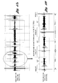
- Figures 4A and 4B provide an additional level of detail for PLC signals and vibration data, such as the data shown in Figure 3.
- Figure 4A shows raw vibration data over the course of an operation cycle for a number of different cutting tools.
- Figure 4B shows a detail of a portion of the raw vibration data broken down into machining operations (cut) and non-machining operations (non cut) for three different cutting tools used in the spindle 14.
- the amplitude of the vibrations during the non-machining operations is much higher than the vibrations during the machining operations. This is because the spindle 14 will often move much faster when it is not cutting a workpiece. Moreover, the interaction of the cutting tool 16 and the workpiece 18 may provide stability to the machine tool 11, thereby reducing overall vibrations. This is one of the reasons that tracking the non-machining operations is an important predictor of the health of a machine tool, such as the machine tool 11.
- Figures 5A and 5B illustrate such data.
- Figure 5A shows raw vibration data for a portion of an operation cycle
- Figure 5B isolates a portion of that data for a single cutting tool.
- Figure 5B includes both machining operations (cut) and non-machining operations (non cut).
- the non-machining operations occurring between specific cuts of the same cutting tool also have much higher vibration amplitudes than the measured vibrations during machining operations.
- the data shown in Figure 5B could represent, for example, four holes drilled with a single drill bit. Therefore, unlike the data shown in Figure 4B, the data shown in Figure 5B includes no tool changes.
- Figure 4B shows raw vibration data from machining operations and non-machining operations for three different cutting tools.
- the non-machining operation data can be analyzed by application of the algorithm to output a parametric representation of the vibration data, which can later be plotted as a non-machining operation-specific trend line.
- One method is to combine all of the non-machining operation data regardless of the particular spindle movement or which cutting tool is installed.
- all of the non-machining operation data (non cut) shown in Figure 4B could be combined to generate a single non-machining operation-specific data point for the operation cycle.
- all of the non-machining operation data for a given operation cycle could be aggregated to output a single point for that operation cycle.
- the individual points generated for each of the operation cycles could then be plotted on a graph, such as shown in Figure 6.
- the parametric representation of the vibration data is a kurtosis, which is shown along the ordinate.
- the abscissa is the cycle number that was performed on the machine tool.
- the abscissa could also be a time value, or alternatively, could be transformed into a frequency domain.
- a non-machining operation-specific trend line such as shown in Figure 6, could be generated for specific cutting tools, or even specific movements of portions of the machine tool, such as the spindle 14 on the machine tool 11.
- each of the non-machining portions of the data represent movement of the spindle 14 between cutting operations for the same cutting tool.
- the non-machining operation data for a single cutting tool could be combined and output into a trend line, such as shown in Figure 6. This would provide a manufacturing manager with an even greater level of detail than aggregating by operation cycle.
- a non-machining operation-specific trend line may be generated, is to choose a particular non-machining operation, such as an acceleration of the spindle 14.
- This particular non-machining operation--e.g., the spindle acceleration--could have vibration data collected on it for a number of different operation cycles. For each of the different operation cycles, a single data point could be generated from only the spindle acceleration data. In this way, the data points could be combined and plotted to generate a trend line, such as the trend line shown in Figure 6. Such a trend line would then represent a very specific non-machining operation analyzed over many cycles. This is another way in which a greater level of detail can be provided to a manufacturing manager.
- an alarm indicator may be provided to alert an operator or manager of a problem with the machine tool 11.
- the alarm can be applied to a trend line, such as the trend line shown in Figure 6.
- the trend line is generally increasing over time. This may be an indication that certain components of the machine tool 11 are becoming worn.
- An alarm could then be applied to the trend line as an upper limit, so that if the trend line exceeded the alarm condition the indicator would provide notice.
- the alarm condition could be set so that a single data point exceeding the alarm condition would set off the indicator. Alternatively, the alarm condition could be set such that it would take a number of data points, or a number of concurrent data points, exceeding the alarm condition to set off the indicator.
- the present invention also contemplates gathering information outside of an operation cycle.
- the vibration sensor 20 and the PLC 28 may still be used to provide data to the processing unit 22.
- Information from the PLC 28 would indicate when the machine tool 11 is outside of an operation cycle, so that this data could be associated with the vibration data collected during this time to define an out-of-cycle data profile.
- the algorithm could then be applied to this out-of-cycle data profile to generate a corresponding out-of-cycle data point.
- a collection of these data points could then be plotted in a trend line, such as the trend line shown in Figure 6.
- an alarm condition could be set for the out-of-cycle data, so that an indicator would alert an operator or manager if the parametric representation of the vibration data exceeded some predetermined alarm condition.
- the maximum vibration amplitude value can be collected and analyzed at a first predetermined frequency, for example, every 12 milliseconds.
- One maximum amplitude value can then archived at a second predetermined frequency, for example, every hour. This regular analysis will likely capture both machining and non-machining data, and can be used to detect crashes in the machine tool 11.
- a "crash" is defined as any event that causes a vibration at the sensor 20 that is greater than a predefined limit value.
- the predefined limit value can be changed for different types of machine applications.
- Crash detection is an overall absolute alarm limit in vibration amplitudes--e.g., measured in multiples of the acceleration due to gravity (g's). It can be active over some time interval, for example, whenever the machine tool 11 is on, or during some shorter time interval. It can be used to collect data in a continuous, real time fashion, regardless of what the machine tool 11 doing.
- the present invention not only provides a method for determining the health of particular components of a machine tool, but also provides a method for detecting crashes before they occur. This type of preventive maintenance can lead to significant savings, both in terms of equipment, and downtime.
Landscapes
- Engineering & Computer Science (AREA)
- Human Computer Interaction (AREA)
- Manufacturing & Machinery (AREA)
- Physics & Mathematics (AREA)
- General Physics & Mathematics (AREA)
- Automation & Control Theory (AREA)
- Numerical Control (AREA)
Abstract
Description
- The present invention relates to a method for managing machine tool data.
- The ever-increasing emphasis on product quality continues to put pressure on manufacturers to find new ways to produce high quality products without increasing production time or otherwise increasing manufacturing costs. Inherent in this high quality, low cost dichotomy is a need to reduce scrap, while obtaining the longest possible life from manufacturing tools and equipment. Thus, increasing the number of tooling changes and/or decreasing the time between machine tool maintenance may increase product quality, but it may result in an unnecessary increase in tooling costs and/or lost production time.
- Over time, manufacturers have developed systems and methods of predictive and preventative maintenance. Such systems may include a scheduled tool change based on a number of parts produced, or scheduled machine down time, during which bearings and other components may be replaced prior to their having an adverse effect on product quality. In order to implement these systems in a cost effective manner, or to reduce the frequency of these preventative maintenance tasks, decision-makers need information. In particular, information that is indicative of historical trends is useful, so that accurate predictions can be made regarding future production runs. In addition, the ability to isolate particular problem areas is also useful; this helps to concentrate efforts where they will have the most impact and produce the most benefit.
- Toward this end, manufacturers have continued to analyze machine tools and their associated components in an effort to gather information they can use to make efficacious decisions regarding their production systems and processes. One type of machine tool analysis used is a vibration analysis. Information gathered from this type of analysis may be indicative of a variety of different production problems.
- One system and method of characterizing a machining process using vibrational signatures of machines is described in U.S. Patent No. 5,663,894, issued to Seth et al. on September 2, 1997. Seth et al. describes characterizing the vibrational signatures of machines by discriminating vibrational activity at various positions on the machines. This is done both with and without machining loads. Both time and frequency domain analysis may then be stored in a database for future comparison and tracking.
- Because a machine tool, during non-machining operations, may see vibrations which are many times higher than those seen during a cutting operation, it may be desirable to isolate non-machining data for separate evaluation from the machining data. This data could then be used as an indicator of the health of the machine tool itself, rather than indicating the health of a particular machining process.
- The present invention provides a method for managing machine tool data that isolates non-machining data from machining data, thereby providing an indicator of the health of the machine tool.
- The invention also provides a method for managing machine tool data, where the machine tool is operable to perform at least one operation cycle which includes at least one machining operation and at least one non-machining operation. The machine tool has at least one sensor operatively connected thereto for sensing a machine operation parameter, and further has a controller configured to output data related to the at least one operation cycle. The method includes operating the machine tool to perform at least a portion of an operation cycle which includes a non-machining operation. Data from signals output from the at least one sensor and from the controller are processed to define a non-machining operation-specific data profile for the non-machining operation. An algorithm is applied to the non-machining operation-specific data profile to generate a non-machining operation-specific data point. This facilitates generation of a non-machining operation-specific trend line.
- A method for managing machine tool data for a machine tool that is operable to perform at least one operation cycle, including at least one machining operation and at least one non-machining operation. The machine tool has at least one sensor operatively connected thereto for sensing a machine operation parameter. The machine tool also has a controller configured to output data related to the at least one operation cycle. The method includes sensing a machine operation parameter for the machine tool for at least a portion of at least one operation cycle including a plurality of non-machining operations. Data related to the sensed parameter is stored, as is data from signals output from the controller. The data from the sensor is associated with the data from the controller, which facilitates defining corresponding non-machining operation-specific data profiles for at least some of the non-machining operations. An algorithm is applied to at least some of the non-machining operation-specific data profiles to generate corresponding non-machining operation-specific data points. The non-machining operation-specific data points are stored, which facilities their subsequent retrieval.
- A method for managing machine tool data, where the machine tool has a controller operatively connected thereto for outputting data related to operation of the machine tool. The method includes performing at least one machining operation, and performing at least one non-machining operation. A machine operation parameter for the machine tool is sensed when it is performing the at least one machining operation and the at least one non-machining operation. The sensed machine operation parameter is associated with data output from the controller, which facilitates defining corresponding machining operation-specific data profiles and non-machining operation-specific data profiles. An algorithm is applied to at least some of the associated data to generate corresponding machining operation-specific data points and non-machining operation-specific data points, which facilitates generation of machining operation-specific trend lines and non-machining operation-specific trend lines.
- The invention will now be described further, by way of example, with reference to the accompanying drawings, in which:
- Figure 1 is a schematic representation of a data management system for a machine tool;
- Figure 2 is a flowchart illustrating an embodiment of a method of the present invention;
- Figure 3 shows raw vibration data collected from a machine tool for eight different cutting tools and associated cycle events;
- Figures 4A and 4B show vibration data for a portion of an operation cycle of a machine tool for different cutting tools;
- Figures 5A and 5B show raw vibration data for a portion of an operation cycle of a machine tool for a single cutting tool; and
- Figure 6 shows a trend line of a parametric representation of vibration data.
- Figure 1 illustrates a
data management system 10 for amachine tool 11. Themachine tool 11 includes abed 12 and aspindle 14. Themachine tool 11, shown in Figure 1, is a computer numerical control (CNC) milling machine. As will readily be discerned from the description below, the present invention can be used with virtually any type of machine tool, including manual as well as CNC machines. - Mounted in the
spindle 14 is acutting tool 16 which is used to machine aworkpiece 18. Attached to thespindle 14 is avibration sensor 20 that is configured to sense vibrations in thespindle 14 and output signals related to the vibrations to aprocessing unit 22. Thevibration sensor 20 may be chosen from any one of a number of types of vibration sensors, such as an accelerometer, a velocity sensor, or any other suitable sensor capable of sensing vibrations. - Of course, other types of sensors may be used--i.e., ones that sense machine operation parameters other than vibrations. For example, a current sensor may be used to measure changes in the amount of current the
machine tool 11 draws during various operations. Similarly, a thermocouple, or other type of temperature sensor, could be used to detect changes in temperature of some portion of themachine tool 11. The spindle speed, torque, or feed rate could also be sensed to provide information relating to the operations. Indeed, any sensor capable of sensing a machine operation parameter can be used to send signals to theprocessing unit 22. - The
processing unit 22 may be conveniently mounted directly on a portion of themachine tool 11, and includes aprocessor 24 and amemory 26. Theprocessor 24 may be programmed to perform specific instruction sets on data, such as vibration data received from thesensor 20. A controller, such as a programmable logic controller (PLC) 28, is also attached to themachine tool 11, and may be programmed with information specific to themachine tool 11, or specific to a machining operation, non-machining operation, or operation cycle performed by themachine tool 11. Theprocessor 24 and thememory 26 are both operatively connected to thesensor 20 and thePLC 28, such that data may be transferred among them. - As noted above, the
PLC 28 may be programmed with information regarding particular machining and non-machining operations. It is configured to output signals related to the operations to theprocessing unit 22. For example, if a set of machining operations are being performed on theworkpiece 18, and this set of operations is part of an operation cycle, thePLC 28 can, among other things, output signals to theprocessing unit 22 delineating different portions of the operation cycle. The operation cycle may include machining and non-machining operations, and thePLC 28 can provide a signal whenever machining starts or finishes. As explained below, this allows vibration signals from thesensor 20 to be associated with particular machining and non-machining operations. - The
PLC 28 may send a tool pickup signal each time a different tool is used in a set of machining operations. ThePLC 28 may also send signals indicating when a particular cutting tool, such as the cuttingtool 16, is performing a particular machining operation. In addition, thePLC 28 may communicate to theprocessing unit 22 when themachine tool 11 is idling, and may further communicate time related data such as the number of machining cycles performed or the number of the workpiece being machined. Thus, by outputting signals related to the machining and non-machining operations, thePLC 28 may communicate to theprocessing unit 22 tool-specific data, idling data, machining and non-machining data, and time related data, just to name a few. Of course, the specific information output from thePLC 28 to theprocessing unit 22 may vary, depending on the type and quantity of information desired. - Figure 2 shows a
flowchart 30 illustrating one embodiment of a method in accordance with the present invention. Atblock 32 an operation cycle is started. As noted above, an operation cycle can include both machining and non-machining operations. As shown in Figure 2, thesensor 20 and thePLC 28 both provide signals which are used in the subsequent data collection. The start of the cycle atblock 32 can be indicated by an audible or visual indicator, such as thecycle LED 34, which may be conveniently integrated into theprocessing unit 22. Atblock 36, a machining or non-machining operation, or event, is started. Atblock 38, raw data is acquired, which in the example shown in Figure 2, includes raw vibration data measured by thesensor 20. - At
block 40 an algorithm is applied to the raw vibration data to generate a parametric representation of the vibration data, which is then output atblock 42. As noted above, thePLC 28 provides signals which can indicate, among other things, whether themachine tool 11 is within an operation cycle, or outside an operation cycle. In addition, ifmachine tool 11 is within an operation cycle, thePLC 28 can provide more specific information, such as when the machine tool is performing a machining operation or a non-machining operation. - The
PLC 28 can also provide signals indicating when these operations start and stop, which cutting tool is in thespindle 14, and other information about the operations. In this way, the raw data can be associated with the data from thePLC 28 to define machining operation-specific data profiles, and non-machining operation-specific data profiles. Thus, when the parametric representation of the raw data is computed atblock 40, the algorithm can be used to generate machining operation-specific data points and non-machining operation-specific data points which can later be used to generate corresponding trend lines for analysis purposes. - The parametric representation of the raw data helps to significantly reduce the size of the data being transferred and stored. The algorithm can be programmed to calculate any of a number of different parametric representations of the raw data. For example, the algorithm may calculate a maximum, a minimum, an average, an average root means square (RMS), a maximum RMS, a minimum RMS, and an RMS summation. Similarly, the algorithm can be programmed to calculate a kurtosis, a kurtosis average, a kurtosis maximum, a kurtosis minimum, a kurtosis standard deviation, and a modified kurtosis formulation. Like the RMS values, the kurtosis values are readily calculated using known statistical formulas, which can be programmed into the algorithm.
- At
step 44, the raw data is dumped, thereby conserving storage space and bandwidth as the data is transferred. As shown inblock 46, the method loops back to block 38 until the particular event is complete. After completion of the particular event, by performing steps 38-46, the process moves on to the next event atstep 48. Then the process loops back to blocks 36-50 until all machining and non-machining events are completed in the particular cycle. - Also at
step 48, information from the completed machining or non-machining operation can be collected atblock 52, where the operation-specific data points can be collected into an operation-specific trend line, which can then be used to analyze the specific operations. In the case of a machining operation, the trend line may provide an indication of the performance of the machining; whereas, in the case of a non-machining operation, the trend line may indicate the health of themachine tool 11 itself, in real time. As described below, an alarm condition can be applied to a trend line, and an indicator provided, such as shown atblock 54, to alert an operator that an alarm condition has be reached. After completion of all machining and non-machining events in the particular cycle, the process moves to the next cycle atblock 55, and loops back to block 32. - As noted above, vibration data can be collected within an operation cycle for both machining operations and non-machining operations. Figure 3 shows a sample of machining and non-machining operation data and machine operation parameter data that can be collected from a machine tool, such as the
machine tool 11 shown in Figure 1, which is used here for reference. As shown in Figure 3, this data ranges over an entire operation cycle. The upper portion of Figure 3 shows a signal provided by thePLC 28 that indicates machining operations performed by eight different tools. - The waveform of the signal provided by the
PLC 28 also shows when the machining operation is between tools. These are examples of non-machining operations. During the non-machining operations, thespindle 14 may be accelerating, decelerating, or both. In addition, the cuttingtool 16 may be removed from thespindle 14, and replaced with another cutting tool. Other non-machining operations could include rapid feeding of thespindle 14 to position, and part positioning/indexing. Each of these processes constitutes a part of the non-machining operations. - The data collected during the non-machining operations may be particularly important as an indicator of the health of the
machine tool 11 itself, including specific portions of themachine tool 11, such as thespindle 14, and the bearings (not shown). The non-machining data may also provide information regarding the cross transmissivity between various slides (not shown) on themachine tool 11. This data provides information regarding how much vibration is transferred from one slide to another as thespindle 14 is being moved. As discussed below, the non-machining operations not only occur during tool changes, but also occur between specific machining operations which take place with the same cutting tool. - Figures 4A and 4B provide an additional level of detail for PLC signals and vibration data, such as the data shown in Figure 3. For example, Figure 4A shows raw vibration data over the course of an operation cycle for a number of different cutting tools. Again using the
machine tool 11 shown in Figure 1 for reference, Figure 4B shows a detail of a portion of the raw vibration data broken down into machining operations (cut) and non-machining operations (non cut) for three different cutting tools used in thespindle 14. - As shown in Figure 4B, the amplitude of the vibrations during the non-machining operations is much higher than the vibrations during the machining operations. This is because the
spindle 14 will often move much faster when it is not cutting a workpiece. Moreover, the interaction of thecutting tool 16 and theworkpiece 18 may provide stability to themachine tool 11, thereby reducing overall vibrations. This is one of the reasons that tracking the non-machining operations is an important predictor of the health of a machine tool, such as themachine tool 11. - As noted above, it may also be of interest to track machining operations, and non-machining operations for a single cutting tool. Figures 5A and 5B illustrate such data. Figure 5A shows raw vibration data for a portion of an operation cycle, and Figure 5B isolates a portion of that data for a single cutting tool. As with Figure 4B, Figure 5B includes both machining operations (cut) and non-machining operations (non cut). Just as with the non-machining operations occurring during tool changes, the non-machining operations occurring between specific cuts of the same cutting tool also have much higher vibration amplitudes than the measured vibrations during machining operations. The data shown in Figure 5B could represent, for example, four holes drilled with a single drill bit. Therefore, unlike the data shown in Figure 4B, the data shown in Figure 5B includes no tool changes.
- As discussed above, application of an algorithm programmed into the
processing unit 22 provides a convenient means for reducing the amount of data gathered from thesensor 20. For example, Figure 4B shows raw vibration data from machining operations and non-machining operations for three different cutting tools. In order to track the health of themachine tool 11, the non-machining operation data can be analyzed by application of the algorithm to output a parametric representation of the vibration data, which can later be plotted as a non-machining operation-specific trend line. - This can be performed in a number of different ways. One method is to combine all of the non-machining operation data regardless of the particular spindle movement or which cutting tool is installed. Thus, for example, all of the non-machining operation data (non cut) shown in Figure 4B could be combined to generate a single non-machining operation-specific data point for the operation cycle. When other operation cycles are run on the
machine tool 11, all of the non-machining operation data for a given operation cycle could be aggregated to output a single point for that operation cycle. The individual points generated for each of the operation cycles could then be plotted on a graph, such as shown in Figure 6. - In the example shown in Figure 6, the parametric representation of the vibration data is a kurtosis, which is shown along the ordinate. Along the abscissa is the cycle number that was performed on the machine tool. The abscissa could also be a time value, or alternatively, could be transformed into a frequency domain. Similarly, a non-machining operation-specific trend line, such as shown in Figure 6, could be generated for specific cutting tools, or even specific movements of portions of the machine tool, such as the
spindle 14 on themachine tool 11. - Using Figure 5B as an example, each of the non-machining portions of the data (non cut) represent movement of the
spindle 14 between cutting operations for the same cutting tool. Rather than aggregating all of the non-machining operation data for an entire operation cycle, the non-machining operation data for a single cutting tool could be combined and output into a trend line, such as shown in Figure 6. This would provide a manufacturing manager with an even greater level of detail than aggregating by operation cycle. - Another way in which a non-machining operation-specific trend line may be generated, is to choose a particular non-machining operation, such as an acceleration of the
spindle 14. This particular non-machining operation--e.g., the spindle acceleration--could have vibration data collected on it for a number of different operation cycles. For each of the different operation cycles, a single data point could be generated from only the spindle acceleration data. In this way, the data points could be combined and plotted to generate a trend line, such as the trend line shown in Figure 6. Such a trend line would then represent a very specific non-machining operation analyzed over many cycles. This is another way in which a greater level of detail can be provided to a manufacturing manager. - As noted in Figure 2, an alarm indicator may be provided to alert an operator or manager of a problem with the
machine tool 11. The alarm can be applied to a trend line, such as the trend line shown in Figure 6. As shown in Figure 6, the trend line is generally increasing over time. This may be an indication that certain components of themachine tool 11 are becoming worn. An alarm could then be applied to the trend line as an upper limit, so that if the trend line exceeded the alarm condition the indicator would provide notice. The alarm condition could be set so that a single data point exceeding the alarm condition would set off the indicator. Alternatively, the alarm condition could be set such that it would take a number of data points, or a number of concurrent data points, exceeding the alarm condition to set off the indicator. - In addition to gathering information from within an operation cycle, the present invention also contemplates gathering information outside of an operation cycle. Thus, when the
machine tool 11 is idling, or otherwise moving without a cutting tool, thevibration sensor 20 and thePLC 28 may still be used to provide data to theprocessing unit 22. Information from thePLC 28 would indicate when themachine tool 11 is outside of an operation cycle, so that this data could be associated with the vibration data collected during this time to define an out-of-cycle data profile. - The algorithm could then be applied to this out-of-cycle data profile to generate a corresponding out-of-cycle data point. A collection of these data points could then be plotted in a trend line, such as the trend line shown in Figure 6. Just as with the other non-machining data, an alarm condition could be set for the out-of-cycle data, so that an indicator would alert an operator or manager if the parametric representation of the vibration data exceeded some predetermined alarm condition.
- Using the output from the
sensor 20 and thePLC 28, the maximum vibration amplitude value can be collected and analyzed at a first predetermined frequency, for example, every 12 milliseconds. One maximum amplitude value can then archived at a second predetermined frequency, for example, every hour. This regular analysis will likely capture both machining and non-machining data, and can be used to detect crashes in themachine tool 11. As used herein, a "crash" is defined as any event that causes a vibration at thesensor 20 that is greater than a predefined limit value. - The predefined limit value can be changed for different types of machine applications. Crash detection is an overall absolute alarm limit in vibration amplitudes--e.g., measured in multiples of the acceleration due to gravity (g's). It can be active over some time interval, for example, whenever the
machine tool 11 is on, or during some shorter time interval. It can be used to collect data in a continuous, real time fashion, regardless of what themachine tool 11 doing. Thus, the present invention not only provides a method for determining the health of particular components of a machine tool, but also provides a method for detecting crashes before they occur. This type of preventive maintenance can lead to significant savings, both in terms of equipment, and downtime.
Claims (11)
- A method for managing machine tool data, the machine tool (11) being operable to perform at least one operation cycle which includes at least one machining operation and at least one non-machining operation, the machine tool 911) having at least one sensor (20) operatively connected thereto for sensing a machine operation parameter, and a controller (28) configured to output data related to the at least one operation cycle, the method comprising:operating the machine tool (11) to perform at least a portion of an operation cycle which includes a non-machining operation;processing data from signals output from the at least one sensor (20) and from the controller (28) to define a non-machining operation-specific data profile for the non-machining operation; andapplying an algorithm to the non-machining operation-specific data profile to generate a non-machining operation-specific data point, thereby facilitating generation of a non-machining operation-specific trend line.
- A method as claimed in claim 1, further comprising:operating the machine tool (11) to perform at least a portion of at least one operation cycle including a plurality of non-machining operations;processing data from signals output from the at least one sensor (20) and from the controller (28) to define a corresponding non-machining operation-specific data profile for at least some of the non-machining operations, thereby facilitating generation of a plurality of non-machining operation-specific data points when the algorithm is applied; andplotting at least some of the non-machining operation-specific data points to generate a non-machining operation-specific trend line.
- A method as claimed in claim 2, wherein the non-machining operations include a certain non-machining operation performed more than once, thereby facilitating generation of a plurality of non-machining operation-specific data points for the certain non-machining operation, and
wherein plotting at least some of the non-machining operation-specific data points includes plotting at least some of the data points for the certain non-machining operation together, thereby generating a non-machining operation-specific trend line for the certain non-machining operation. - A method as claimed in claim 2 or 3, the machine tool (11) including a spindle (14), and wherein the non-machining operations include a spindle acceleration, a spindle deceleration, or both.
- A method as claimed in any of claims 2 to 4, further comprising:determining an alarm condition for the certain non-machining operation;applying the alarm condition to the non-machining operation-specific trend line; andindicating the alarm condition when the non-machining operation-specific trend line reaches the alarm condition.
- A method as claimed in any preceding claim, wherein the at least one sensor (20) is configured to sense at least one of vibrations, current, temperature, torque or speed.
- A method as claimed in claim 1, wherein operating the machine tool (11) to perform at least a portion of an operation cycle includes performing first and second machining operations with a first cutting tool (16), and wherein the at least one non-machining operation includes operating the machine tool (11) between the first and second machining operations.
- A method as claimed in claim 1, wherein operating the machine tool (11) to perform at least a portion of an operation cycle includes operating the machine tool (11) with at least a first and second cutting tool to perform respective machining operations, and wherein the at least one non-machining operation includes changing the cutting tool from the first cutting tool (16) to the second cutting tool.
- A method as claimed in claim 1, further comprising:operating the machine tool (11) outside of an operation cycle;processing data from signals output from the at least one sensor (20) and from the controller (28) to define at least one out-of-cycle data profile; andapplying the algorithm to the at least one out-of-cycle data profile to generate a corresponding out-of-cycle data point.
- A method as claimed in any preceding claim, wherein applying the algorithm to the non-machining operation-specific data profile includes generating a parametric representation of the non-machining operation-specific data profile, the parametric representation including at least one of a maximum, a minimum, an average, an average root mean square, a maximum root mean square, a minimum root mean square, a root mean square summation, a kurtosis, a kurtosis average, a kurtosis maximum, a kurtosis minimum, a kurtosis standard deviation.
- A method as claimed in claim 1, wherein the machine operation parameter for the machine tool (11) is continuously sensed over some time interval, the method further comprising:determining a maximum value of the machine operation parameter at a first predetermined frequency;storing the maximum value of the determined machine operation parameter at a second predetermined frequency; andcomparing the stored maximum values to a predetermined limit value.
Applications Claiming Priority (2)
| Application Number | Priority Date | Filing Date | Title |
|---|---|---|---|
| US10/904,119 US7409261B2 (en) | 2004-10-25 | 2004-10-25 | Data management and networking system and method |
| US11/161,377 US7383097B2 (en) | 2004-10-25 | 2005-08-01 | Method for managing machine tool data |
Publications (1)
| Publication Number | Publication Date |
|---|---|
| EP1650623A1 true EP1650623A1 (en) | 2006-04-26 |
Family
ID=35781450
Family Applications (1)
| Application Number | Title | Priority Date | Filing Date |
|---|---|---|---|
| EP05109130A Ceased EP1650623A1 (en) | 2004-10-25 | 2005-10-02 | Method for managing machine tool data |
Country Status (2)
| Country | Link |
|---|---|
| US (1) | US7383097B2 (en) |
| EP (1) | EP1650623A1 (en) |
Cited By (2)
| Publication number | Priority date | Publication date | Assignee | Title |
|---|---|---|---|---|
| WO2016128709A1 (en) * | 2015-02-12 | 2016-08-18 | Edwards Limited | Processing tool monitoring |
| US11604456B2 (en) * | 2020-03-11 | 2023-03-14 | Ford Global Technologies, Llc | System for monitoring machining processes of a computer numerical control machine |
Families Citing this family (15)
| Publication number | Priority date | Publication date | Assignee | Title |
|---|---|---|---|---|
| US7571022B2 (en) * | 2004-10-25 | 2009-08-04 | Ford Motor Company | System and method for monitoring machine health |
| US20070088454A1 (en) * | 2004-10-25 | 2007-04-19 | Ford Motor Company | System and method for troubleshooting a machine |
| US8380462B2 (en) * | 2010-09-16 | 2013-02-19 | Ford Motor Company | System and method for setting machine limits |
| US8786455B2 (en) | 2011-06-23 | 2014-07-22 | Ford Motor Company | Tool lubrication delivery monitoring system and method |
| US20130158912A1 (en) * | 2011-12-15 | 2013-06-20 | Chung-Shan Institute of Science and Technology, Armaments, Bureau, Ministry of National Defence | Apparatus for Measuring the State of Health of a Cell Pack |
| JP5462296B2 (en) * | 2012-02-13 | 2014-04-02 | ファナック株式会社 | Machine tool warm-up operation control device |
| US9260943B2 (en) * | 2013-10-23 | 2016-02-16 | Schlumberger Technology Corporation | Tool health evaluation system and methodology |
| JP5890467B2 (en) * | 2014-05-26 | 2016-03-22 | ファナック株式会社 | Machine tool with warm-up operation function |
| US10365633B2 (en) | 2017-06-14 | 2019-07-30 | Ford Motor Company | Method for generating CNC machine offset based on thermal model |
| US10753823B2 (en) | 2017-10-10 | 2020-08-25 | Ford Motor Company | Dynamic characterization system for measuring a dynamic response |
| WO2019083565A1 (en) * | 2017-10-23 | 2019-05-02 | Johnson Controls Technology Company | Building management system with automated vibration data analysis |
| US10895873B2 (en) * | 2018-04-25 | 2021-01-19 | Aktiebolaget Skf | Machine health monitoring of rotating machinery |
| US10739754B2 (en) | 2018-05-11 | 2020-08-11 | Ford Motor Company | Method and system for monitoring machine health to improve machine cycle time impact |
| CN115415848B (en) * | 2022-08-26 | 2023-09-19 | 重庆长安汽车股份有限公司 | Method and system for detecting precision of machining center equipment |
| CN117798390B (en) * | 2023-12-29 | 2024-10-15 | 新昌合旸汽车零部件有限公司 | Automatic production device for automobile bearings |
Citations (3)
| Publication number | Priority date | Publication date | Assignee | Title |
|---|---|---|---|---|
| US5181898A (en) * | 1991-09-16 | 1993-01-26 | Cincinnati Milacron, Inc. | Cover assembly for multi-configurable machine tool |
| US5663894A (en) * | 1995-09-06 | 1997-09-02 | Ford Global Technologies, Inc. | System and method for machining process characterization using mechanical signature analysis |
| US20040176926A1 (en) * | 2003-03-06 | 2004-09-09 | Edie Paul Charles | System and method for machining data management |
Family Cites Families (53)
| Publication number | Priority date | Publication date | Assignee | Title |
|---|---|---|---|---|
| US4723219A (en) * | 1985-06-21 | 1988-02-02 | Amca International Corporation | Programmed path for automatic tool retraction and return responsive to degradation threshold |
| US4823061A (en) * | 1985-12-16 | 1989-04-18 | Delapena Honing Equipment Limited | Stone expansion control for a honing machine |
| US4985857A (en) * | 1988-08-19 | 1991-01-15 | General Motors Corporation | Method and apparatus for diagnosing machines |
| US5119318A (en) * | 1989-04-17 | 1992-06-02 | Del Partners L.P. | Expert control system for real time management of automated factory equipment |
| JP3224226B2 (en) * | 1989-09-22 | 2001-10-29 | 株式会社リコー | Fault diagnosis expert system |
| US5339257A (en) * | 1991-05-15 | 1994-08-16 | Automated Technology Associates Inc. | Real-time statistical process monitoring system |
| US5407265A (en) * | 1992-07-06 | 1995-04-18 | Ford Motor Company | System and method for detecting cutting tool failure |
| JPH0866893A (en) * | 1994-08-24 | 1996-03-12 | Fanuc Ltd | Collision detecting method |
| KR960043307A (en) * | 1995-05-11 | 1996-12-23 | 김광호 | Chemical processing device central management system |
| US5662568A (en) * | 1995-05-12 | 1997-09-02 | Ingersoll Milling Machine Co. | Symmetrical multi-axis linear motor machine tool |
| US5694596A (en) * | 1995-05-25 | 1997-12-02 | Kangaroo, Inc. | On-line database updating network system and method |
| US6240451B1 (en) * | 1995-05-25 | 2001-05-29 | Punch Networks Corporation | Method and apparatus for automatically disseminating information over a network |
| US5896292A (en) * | 1995-06-05 | 1999-04-20 | Canon Kabushiki Kaisha | Automated system for production facility |
| JPH09244728A (en) * | 1996-03-13 | 1997-09-19 | Fanuc Ltd | Data display and input method of cnc device utilized as on-line terminal |
| US5857166A (en) * | 1996-08-30 | 1999-01-05 | Kim; Nam H. | Tool monitoring apparatus |
| JPH10124131A (en) * | 1996-10-22 | 1998-05-15 | Fanuc Ltd | Method for managing equipment connected to controller |
| US6470377B1 (en) * | 1997-12-19 | 2002-10-22 | Rockwell Automation Technologies, Inc. | Networked file operations for computer numerical controls |
| US6161051A (en) * | 1998-05-08 | 2000-12-12 | Rockwell Technologies, Llc | System, method and article of manufacture for utilizing external models for enterprise wide control |
| US6484109B1 (en) * | 1998-05-20 | 2002-11-19 | Dli Engineering Coporation | Diagnostic vibration data collector and analyzer |
| US6289735B1 (en) * | 1998-09-29 | 2001-09-18 | Reliance Electric Technologies, Llc | Machine diagnostic system and method for vibration analysis |
| US6697894B1 (en) * | 1999-03-29 | 2004-02-24 | Siemens Dematic Postal Automation, L.P. | System, apparatus and method for providing maintenance instructions to a user at a remote location |
| US6947797B2 (en) * | 1999-04-02 | 2005-09-20 | General Electric Company | Method and system for diagnosing machine malfunctions |
| JP2003502771A (en) * | 1999-06-22 | 2003-01-21 | ブルックス オートメーション インコーポレイテッド | Run-to-run controller used for microelectronics fabrication |
| US6606665B2 (en) * | 1999-09-27 | 2003-08-12 | Rockwell Automation Technologies, Inc. | Multiple connection architecture for communication with a computer numerical control resident in a workstation and other networked computer numerical controls |
| US6324659B1 (en) * | 1999-10-28 | 2001-11-27 | General Electric Company | Method and system for identifying critical faults in machines |
| US6741265B2 (en) * | 1999-11-24 | 2004-05-25 | General Electric Company | Network-based design systems and methods |
| DE10007126B4 (en) * | 2000-02-17 | 2006-06-22 | Paul Müller GmbH & Co. KG Unternehmensbeteiligungen | Spindle with a data storage element |
| EP1162029B1 (en) * | 2000-05-15 | 2003-03-19 | Prometec GmbH | Method and device for monitoring the wear of a tool |
| US6474913B2 (en) * | 2000-05-31 | 2002-11-05 | Toshiba Kikai Kabushiki Kaisha | Tool management system |
| JP2001350510A (en) * | 2000-06-06 | 2001-12-21 | Mori Seiki Co Ltd | Machine tool maintenance management system |
| JP2002063240A (en) * | 2000-06-06 | 2002-02-28 | Mori Seiki Co Ltd | production management system |
| US6219895B1 (en) * | 2000-06-27 | 2001-04-24 | Davenport Industries, Llc | Machine tool with servo drive mechanism |
| EP1303797B1 (en) * | 2000-07-22 | 2007-05-23 | Abb Research Ltd. | System for support of an error cause analysis |
| US6643592B1 (en) * | 2000-10-05 | 2003-11-04 | General Electric Company | System and method for fault diagnosis |
| US6738748B2 (en) * | 2001-04-03 | 2004-05-18 | Accenture Llp | Performing predictive maintenance on equipment |
| US6496789B2 (en) * | 2000-12-16 | 2002-12-17 | Ford Global Technologies, Inc. | Spindle characterization system |
| US6882961B2 (en) * | 2000-12-20 | 2005-04-19 | Caterpillar Inc | Method and system for providing diagnostics for a work machines |
| US6575034B2 (en) * | 2001-01-30 | 2003-06-10 | Ford Global Technologies, L.L.C. | Characterization of environmental and machinery induced vibration transmissivity |
| DE10195976T5 (en) * | 2001-02-22 | 2004-04-29 | Mitsubishi Denki K.K. | Numerical control method and device |
| TW559706B (en) * | 2001-06-08 | 2003-11-01 | Hon Hai Prec Ind Co Ltd | Method and system for collecting and monitoring shop floor information |
| DE10152765B4 (en) * | 2001-07-13 | 2015-11-12 | Siemens Aktiengesellschaft | A method for electronically providing services to machines via a data communication link |
| US7552203B2 (en) * | 2001-10-17 | 2009-06-23 | The Boeing Company | Manufacturing method and software product for optimizing information flow |
| US7054761B2 (en) * | 2002-01-18 | 2006-05-30 | Spm Instrument Ab | Analysis system for analyzing the condition of a machine |
| JP2003242271A (en) * | 2002-02-13 | 2003-08-29 | Toshiba Corp | Plant diagnostic method and diagnostic system |
| JP2004295348A (en) * | 2003-03-26 | 2004-10-21 | Mori Seiki Co Ltd | Machine tool maintenance management system |
| JP4171363B2 (en) * | 2003-07-11 | 2008-10-22 | 西部電機株式会社 | High-speed curved surface machining method that cuts a workpiece into an arbitrary curved surface |
| DE10348608B4 (en) * | 2003-10-20 | 2016-05-19 | Siemens Aktiengesellschaft | Monitoring system and method for a spindle |
| US20050097405A1 (en) * | 2003-11-03 | 2005-05-05 | Robert Sesek | Systems and methods for reporting device problems |
| US20050218192A1 (en) * | 2004-03-31 | 2005-10-06 | Jeff Lovin | Method and system of inertia friction welding |
| US7831704B2 (en) * | 2004-04-22 | 2010-11-09 | General Electric Company | Methods and systems for monitoring and diagnosing machinery |
| US7409261B2 (en) * | 2004-10-25 | 2008-08-05 | Ford Motor Company | Data management and networking system and method |
| US7571022B2 (en) * | 2004-10-25 | 2009-08-04 | Ford Motor Company | System and method for monitoring machine health |
| JP5043839B2 (en) * | 2005-07-11 | 2012-10-10 | ブルックス オートメーション インコーポレイテッド | Intelligent condition monitoring and fault diagnosis system for predictive maintenance |
-
2005
- 2005-08-01 US US11/161,377 patent/US7383097B2/en not_active Expired - Lifetime
- 2005-10-02 EP EP05109130A patent/EP1650623A1/en not_active Ceased
Patent Citations (3)
| Publication number | Priority date | Publication date | Assignee | Title |
|---|---|---|---|---|
| US5181898A (en) * | 1991-09-16 | 1993-01-26 | Cincinnati Milacron, Inc. | Cover assembly for multi-configurable machine tool |
| US5663894A (en) * | 1995-09-06 | 1997-09-02 | Ford Global Technologies, Inc. | System and method for machining process characterization using mechanical signature analysis |
| US20040176926A1 (en) * | 2003-03-06 | 2004-09-09 | Edie Paul Charles | System and method for machining data management |
Cited By (5)
| Publication number | Priority date | Publication date | Assignee | Title |
|---|---|---|---|---|
| WO2016128709A1 (en) * | 2015-02-12 | 2016-08-18 | Edwards Limited | Processing tool monitoring |
| GB2535456A (en) * | 2015-02-12 | 2016-08-24 | Edwards Ltd | Processing tool monitoring |
| TWI688845B (en) * | 2015-02-12 | 2020-03-21 | 英商愛德華有限公司 | Processing tool monitoring |
| US10802941B2 (en) | 2015-02-12 | 2020-10-13 | Edwards Limited | Processing tool monitoring |
| US11604456B2 (en) * | 2020-03-11 | 2023-03-14 | Ford Global Technologies, Llc | System for monitoring machining processes of a computer numerical control machine |
Also Published As
| Publication number | Publication date |
|---|---|
| US7383097B2 (en) | 2008-06-03 |
| US20060089744A1 (en) | 2006-04-27 |
Similar Documents
| Publication | Publication Date | Title |
|---|---|---|
| US6845340B2 (en) | System and method for machining data management | |
| EP1650624B1 (en) | System and method for monitoring machine health | |
| US7383097B2 (en) | Method for managing machine tool data | |
| CN115922442B (en) | Real-time monitoring method and related device for tool wear and damage based on spindle vibration signal | |
| TWI640390B (en) | Tool wear monitoring and predicting method | |
| US20070088454A1 (en) | System and method for troubleshooting a machine | |
| US7341410B2 (en) | Dynamical instrument for machining | |
| WO2008142386A1 (en) | Machining process monitor | |
| JP7342444B2 (en) | Processing tool abnormality detection device | |
| EP1650622B1 (en) | Data management and networking system and method | |
| JP6717795B2 (en) | Integrated processing system, integrated processing method and program | |
| CN114800040A (en) | Cutter wear monitoring method and system based on process-state data correlation | |
| JP2023510463A (en) | Methods for monitoring and/or predicting machining processes and/or machining results | |
| JP7036763B2 (en) | Tool change timing management system | |
| US11226613B2 (en) | Anomaly detection device, anomaly detection server and anomaly detection method | |
| JP6629672B2 (en) | Processing equipment | |
| JP2001205545A (en) | Tool replacement timing judging system | |
| JP7310195B2 (en) | Diagnostic device, diagnostic system and diagnostic program | |
| Dornfeld | Monitoring of the machining process by means of acoustic emission sensors | |
| KR101170323B1 (en) | Monitoring method for condition of machining system with current value of spindle motor | |
| JP2025015081A (en) | Abnormality detection device and abnormality detection method of cutting tool | |
| Ogedengbe et al. | Feasibility of tool condition monitoring on micro-milling using current signals | |
| EP4394533A1 (en) | Methods and systems for monitoring a process of manufacturing a workpiece by a machining tool | |
| JP7783297B2 (en) | Abnormality diagnosis device, abnormality diagnosis system, and storage medium | |
| JP7576594B2 (en) | Cutting system and cutting method |
Legal Events
| Date | Code | Title | Description |
|---|---|---|---|
| PUAI | Public reference made under article 153(3) epc to a published international application that has entered the european phase |
Free format text: ORIGINAL CODE: 0009012 |
|
| AK | Designated contracting states |
Kind code of ref document: A1 Designated state(s): AT BE BG CH CY CZ DE DK EE ES FI FR GB GR HU IE IS IT LI LT LU LV MC NL PL PT RO SE SI SK TR |
|
| AX | Request for extension of the european patent |
Extension state: AL BA HR MK YU |
|
| 17P | Request for examination filed |
Effective date: 20060824 |
|
| 17Q | First examination report despatched |
Effective date: 20060925 |
|
| AKX | Designation fees paid |
Designated state(s): DE GB SE |
|
| STAA | Information on the status of an ep patent application or granted ep patent |
Free format text: STATUS: THE APPLICATION HAS BEEN REFUSED |
|
| 18R | Application refused |
Effective date: 20100324 |
|
| P01 | Opt-out of the competence of the unified patent court (upc) registered |
Effective date: 20230620 |