EP1650610A1 - Control of cooling in induction image heating apparatus - Google Patents
Control of cooling in induction image heating apparatus Download PDFInfo
- Publication number
- EP1650610A1 EP1650610A1 EP05023038A EP05023038A EP1650610A1 EP 1650610 A1 EP1650610 A1 EP 1650610A1 EP 05023038 A EP05023038 A EP 05023038A EP 05023038 A EP05023038 A EP 05023038A EP 1650610 A1 EP1650610 A1 EP 1650610A1
- Authority
- EP
- European Patent Office
- Prior art keywords
- induction coil
- heat
- temperature
- rotation member
- magnetic flux
- Prior art date
- Legal status (The legal status is an assumption and is not a legal conclusion. Google has not performed a legal analysis and makes no representation as to the accuracy of the status listed.)
- Granted
Links
- 230000006698 induction Effects 0.000 title claims abstract description 104
- 238000001816 cooling Methods 0.000 title claims abstract description 55
- 238000010438 heat treatment Methods 0.000 title claims abstract description 46
- 230000004907 flux Effects 0.000 claims abstract description 35
- 239000000463 material Substances 0.000 claims description 13
- 238000001514 detection method Methods 0.000 claims description 5
- 230000001276 controlling effect Effects 0.000 claims description 4
- 230000001105 regulatory effect Effects 0.000 claims description 4
- 230000000694 effects Effects 0.000 abstract description 5
- 230000017525 heat dissipation Effects 0.000 description 7
- 230000003247 decreasing effect Effects 0.000 description 6
- 230000007246 mechanism Effects 0.000 description 5
- 239000002184 metal Substances 0.000 description 5
- 229910052736 halogen Inorganic materials 0.000 description 4
- 150000002367 halogens Chemical class 0.000 description 4
- 239000010410 layer Substances 0.000 description 4
- 229920005989 resin Polymers 0.000 description 4
- 239000011347 resin Substances 0.000 description 4
- 239000003570 air Substances 0.000 description 3
- 239000011248 coating agent Substances 0.000 description 3
- 238000000576 coating method Methods 0.000 description 3
- 238000002844 melting Methods 0.000 description 3
- 230000008018 melting Effects 0.000 description 3
- 239000012080 ambient air Substances 0.000 description 2
- 238000006243 chemical reaction Methods 0.000 description 2
- 230000020169 heat generation Effects 0.000 description 2
- 230000006872 improvement Effects 0.000 description 2
- 239000002344 surface layer Substances 0.000 description 2
- 238000010792 warming Methods 0.000 description 2
- KXGFMDJXCMQABM-UHFFFAOYSA-N 2-methoxy-6-methylphenol Chemical compound [CH]OC1=CC=CC([CH])=C1O KXGFMDJXCMQABM-UHFFFAOYSA-N 0.000 description 1
- REEBJQTUIJTGAL-UHFFFAOYSA-N 3-pyridin-1-ium-1-ylpropane-1-sulfonate Chemical compound [O-]S(=O)(=O)CCC[N+]1=CC=CC=C1 REEBJQTUIJTGAL-UHFFFAOYSA-N 0.000 description 1
- YCKRFDGAMUMZLT-UHFFFAOYSA-N Fluorine atom Chemical compound [F] YCKRFDGAMUMZLT-UHFFFAOYSA-N 0.000 description 1
- 239000004696 Poly ether ether ketone Substances 0.000 description 1
- 239000004734 Polyphenylene sulfide Substances 0.000 description 1
- JUPQTSLXMOCDHR-UHFFFAOYSA-N benzene-1,4-diol;bis(4-fluorophenyl)methanone Chemical compound OC1=CC=C(O)C=C1.C1=CC(F)=CC=C1C(=O)C1=CC=C(F)C=C1 JUPQTSLXMOCDHR-UHFFFAOYSA-N 0.000 description 1
- 230000015572 biosynthetic process Effects 0.000 description 1
- 238000007664 blowing Methods 0.000 description 1
- 238000004140 cleaning Methods 0.000 description 1
- 239000011247 coating layer Substances 0.000 description 1
- 239000004020 conductor Substances 0.000 description 1
- 230000008094 contradictory effect Effects 0.000 description 1
- 229920001971 elastomer Polymers 0.000 description 1
- 230000005674 electromagnetic induction Effects 0.000 description 1
- 229910052731 fluorine Inorganic materials 0.000 description 1
- 239000011737 fluorine Substances 0.000 description 1
- 230000009191 jumping Effects 0.000 description 1
- 230000004048 modification Effects 0.000 description 1
- 238000012986 modification Methods 0.000 description 1
- 230000002093 peripheral effect Effects 0.000 description 1
- 229920001568 phenolic resin Polymers 0.000 description 1
- 239000005011 phenolic resin Substances 0.000 description 1
- 229920002530 polyetherether ketone Polymers 0.000 description 1
- 229920000069 polyphenylene sulfide Polymers 0.000 description 1
- 239000004810 polytetrafluoroethylene Substances 0.000 description 1
- 229920001343 polytetrafluoroethylene Polymers 0.000 description 1
- 230000002035 prolonged effect Effects 0.000 description 1
- 230000005855 radiation Effects 0.000 description 1
- 229920006395 saturated elastomer Polymers 0.000 description 1
- 229920002379 silicone rubber Polymers 0.000 description 1
- 239000004945 silicone rubber Substances 0.000 description 1
Images





Classifications
-
- G—PHYSICS
- G03—PHOTOGRAPHY; CINEMATOGRAPHY; ANALOGOUS TECHNIQUES USING WAVES OTHER THAN OPTICAL WAVES; ELECTROGRAPHY; HOLOGRAPHY
- G03G—ELECTROGRAPHY; ELECTROPHOTOGRAPHY; MAGNETOGRAPHY
- G03G15/00—Apparatus for electrographic processes using a charge pattern
- G03G15/20—Apparatus for electrographic processes using a charge pattern for fixing, e.g. by using heat
- G03G15/2003—Apparatus for electrographic processes using a charge pattern for fixing, e.g. by using heat using heat
- G03G15/2014—Apparatus for electrographic processes using a charge pattern for fixing, e.g. by using heat using heat using contact heat
- G03G15/2039—Apparatus for electrographic processes using a charge pattern for fixing, e.g. by using heat using heat using contact heat with means for controlling the fixing temperature
- G03G15/205—Apparatus for electrographic processes using a charge pattern for fixing, e.g. by using heat using heat using contact heat with means for controlling the fixing temperature specially for the mode of operation, e.g. standby, warming-up, error
-
- G—PHYSICS
- G03—PHOTOGRAPHY; CINEMATOGRAPHY; ANALOGOUS TECHNIQUES USING WAVES OTHER THAN OPTICAL WAVES; ELECTROGRAPHY; HOLOGRAPHY
- G03G—ELECTROGRAPHY; ELECTROPHOTOGRAPHY; MAGNETOGRAPHY
- G03G15/00—Apparatus for electrographic processes using a charge pattern
- G03G15/20—Apparatus for electrographic processes using a charge pattern for fixing, e.g. by using heat
- G03G15/2003—Apparatus for electrographic processes using a charge pattern for fixing, e.g. by using heat using heat
- G03G15/2014—Apparatus for electrographic processes using a charge pattern for fixing, e.g. by using heat using heat using contact heat
- G03G15/2017—Structural details of the fixing unit in general, e.g. cooling means, heat shielding means
- G03G15/2021—Plurality of separate fixing and/or cooling areas or units, two step fixing
-
- G—PHYSICS
- G03—PHOTOGRAPHY; CINEMATOGRAPHY; ANALOGOUS TECHNIQUES USING WAVES OTHER THAN OPTICAL WAVES; ELECTROGRAPHY; HOLOGRAPHY
- G03G—ELECTROGRAPHY; ELECTROPHOTOGRAPHY; MAGNETOGRAPHY
- G03G15/00—Apparatus for electrographic processes using a charge pattern
- G03G15/20—Apparatus for electrographic processes using a charge pattern for fixing, e.g. by using heat
- G03G15/2003—Apparatus for electrographic processes using a charge pattern for fixing, e.g. by using heat using heat
- G03G15/2014—Apparatus for electrographic processes using a charge pattern for fixing, e.g. by using heat using heat using contact heat
- G03G15/2064—Apparatus for electrographic processes using a charge pattern for fixing, e.g. by using heat using heat using contact heat combined with pressure
-
- G—PHYSICS
- G03—PHOTOGRAPHY; CINEMATOGRAPHY; ANALOGOUS TECHNIQUES USING WAVES OTHER THAN OPTICAL WAVES; ELECTROGRAPHY; HOLOGRAPHY
- G03G—ELECTROGRAPHY; ELECTROPHOTOGRAPHY; MAGNETOGRAPHY
- G03G2215/00—Apparatus for electrophotographic processes
- G03G2215/20—Details of the fixing device or porcess
- G03G2215/2003—Structural features of the fixing device
- G03G2215/2016—Heating belt
- G03G2215/2025—Heating belt the fixing nip having a rotating belt support member opposing a pressure member
Definitions
- the present invention relates to an image heating apparatus for heating an image on a recording material.
- the image heating apparatus there are a fixation apparatus for fixing a unfixed image on the recording material, a gloss-imparting apparatus for improving a gloss of an image by heating the image fixed on the recording material.
- FIG. 2 is a schematic sectional view of an electrophotographic apparatus.
- a photosensitive drum 1 is electrically charged by a charging apparatus 2 and an original or data are converted into light L by an original-supporting plate or a laser scanner.
- the photosensitive drum is exposed to the light L, so that an electric potential is lowered at an exposed portion, thus being different from that an unexposed portion.
- a manner of jumping of toner t in a developing apparatus to the photosensitive drum 1 varies, so that an image is formed.
- the resultant toner image formed on the photosensitive drum is transferred onto a recording material P by a transfer apparatus 5.
- toner remaining on the photosensitive drum 1 without being transferred is recovered by a cleaning apparatus 6.
- the recording material P onto which the toner image is transferred is conveyed to a fixing apparatus 7 by which the toner image is fixed.
- FIG 3 is a schematic sectional view of a conventional fixing apparatus usable in the electrophotographic apparatus.
- the fixing apparatus 7 includes a fixation roller 8 for melting the toner t on the recording material P and a pressure roller 9 for pressing the recording material P against the fixation roller 9.
- the fixation roller 8 is formed in a hollow shape and is provided with a halogen lamp at the inside thereof. A predetermined voltage is applied to the halogen lamp to generate heat.
- an induction heating-type heating apparatus utilizing high-frequency induction as a heating source has been proposed (e.g., Japanese Laid-Open Patent Application (JP-A) Sho 59-33787).
- JP-A Japanese Laid-Open Patent Application
- a coil is concentrically disposed inside a hollow fixation roller formed o a metal conductor and is supplied with a high-frequency current to generate a high-frequency magnetic field, whereby an induction eddy current is generated on the fixation roller to cause the fixation roller per se to generate Joule heat by a skin resistance of the fixation roller itself.
- an electrothermal conversion efficiency is considerably improved, so that it becomes possible to reduce a warm-up time.
- heat dissipation is also performed during the warming up which is not required to dissipate heat by the heat dissipation plate, so that the warm-up time is prolonged to increase an amount of power consumption during fixation standby when compared with the case where the heat dissipation plate is not disposed.
- An object of the present invention is to provide an image heating apparatus capable of cooling a coil by a simple constitution.
- an image heating apparatus comprising:
- an image heating apparatus comprising:
- FIG 4 is a schematic sectional view of an induction heating apparatus in this embodiment of the present invention.
- a constitution of an electrophotographic apparatus including the induction heating apparatus as a fixation apparatus is the same as that described above with reference to Figure 2 except that the constitution of the fixation apparatus is different, thus being omitted from specific explanation.
- a fixation roller 8 as a heat rotation member which generates heat by electromagnetic induction comprises an iron-made core metal cylinder having an outer diameter of 40 mm, a thickness of 0.7 mm, and a length of 340 mm and a surface layer of a fluorine-containing resin, such as PFA or PTFE, for improving a surface releasability.
- a fluorine-containing resin such as PFA or PTFE
- a pressure roller 9 as a nip forming member is constituted by a hollow core metal having an outer diameter of 35 mm, a thickness of 3 mm, and a length of 340 mm, and a heat insulating layer which is formed as a heat-resistant rubber layer having a surface releasability at a peripheral surface of the core metal.
- the fixation roller 8 and the pressure roller 9 are rotatably supported and pressed against each other by an unshown pressure mechanism, thus forming a fixation nip N having a width of about 5 mm.
- the fixation roller 8 is driven at a speed of 300 mm/sec by an unshown rotation motor, and the pressure roller 9 is rotated by a frictional force with the fixation roller 8 at the fixation nip N.
- a recording sheet P is introduced in the fixation nip N while carrying thereon unfixed toner image t, and the toner image t is heated under pressure to become a fixed image.
- An induction coil 13 is held by a core 12 (12a, 12b) in an unshown holder formed of a heat-resistant magnetic resin, such as PPS, PEEK, phenolic resin, etc., and by a stay (not shown).
- a heat-resistant magnetic resin such as PPS, PEEK, phenolic resin, etc.
- an AC current of 10 - 100 kHz is applied, whereby an eddy current is generated at an inner surface, which is an electroconductive layer, of the fixation roller 8 by a magnetic field induced by the AC current, thus generating Joule heat.
- the induction coil per se also generates heat by an internal resistance thereof.
- this state is such a state that the temperature of the induction coil in the fixation roller at its central portion is predicted that it reaches 230 °C on the basis of previous study as shown in Figure 5.
- a coating resin of the induction coil is formed of a material which is melted at 235 °C, so that there is a possibility that the induction coil becomes electrically shorted.
- Figure 1 is a time-line chart showing progressions of a induction coil temperature and a fixation roller temperature with time in a pre-stage of the cooling sequence, in an execution stage of the cooling sequence, and after completion of the cooling sequence.
- Figure 1 also shows progressions of energization of the induction coil a rotation speed of the fixation roller, a position of a magnetic flux shielding plate, a nip pressure between the fixation roller and the pressure roller, and the cooling sequence.
- the cooling sequence when the temperature of the induction coil reaches 230 °C (predetermined temperature) (or is predicted that it reaches 230 °C), the image forming job is temporarily stopped and power supply to the induction coil by a control apparatus (energization control means) 100 is turned off. In this state, the cooling sequence is started by rotating the fixation roller 8 and the pressure roller 9 by using a rotation control means 16.
- the power supply to the induction coil is turned off, so that there is no heat generation due to the internal resistance of the induction coil. Further, by idle rotation of the fixation roller, a high-temperature ambient air between the fixation roller and the induction coil is dissipated outside the fixation roller.
- the fixation roller is rotated at idle in contact with the pressure roller, so that the heat of the fixation roller is also released into the pressure roller. This is because the pressure roller is not provided with a heat source, thus having a lower temperature. Further, by the idle rotation of the fixation roller, the heat is also released into ambient air. As described above, the cooling sequence has two cooling functions.
- the induction coil temperature is lowered to a restore set temperature of 200 °C.
- a time required to resume the sheet passing operation was about 180 sec as shown in Figure 6 in the case where both of the fixation roller and the pressure roller are rotated while temperature-controlling the fixation roller so as to be kept at a certain temperature by a conventional temperature detection means 11. Further, in the case of using a fan, the time was 120 sec.
- the induction coil temperature is gradually lowered but an irregularity in temperature particularly between the fixation nip portion and another (non-nip) portion (e.g., at a lowest temperature position) is caused to occur, so that irregularities in fixability and gloss are caused to occur if left uncontrolled. Further, the fixation roller is not rotated, so that an amount of heat released into air is also decreased. For this reason, the above described time which also including a time required for removal of the irregularities is 130 sec for resumption of the sheet passing operation.
- the induction coil temperature is measured by disposing a thermocouple in the neighborhood of the induction coil.
- the time for the resumption is 75 sec without using a particular cooling mechanism.
- the temperature of induction coil is predicted by the temperature detection means of the fixation roller and the continuous energization time of the induction coil but may also be predicted by other conditions or be directly detected to performed the cooling sequence.
- the continuous energization time is measured by a timer provided in the control apparatus.
- the continuous energization time of the induction coil refers to a time period during which energization of the induction coil is continued when a plurality of recording sheets are continuously subjected to image formation.
- counting of the energization time is not stopped by "energization off" but is continued as it is.
- a basic constitution is the same as in Embodiment 1 except that the fixation apparatus further includes a magnetic flux shielding means which can be disposed between the induction coil and the fixation roller to shield generated magnetic flux at both end portions of the fixation roller in its axial direction. More specifically, as shown in Figure 4, by a magnetic flux shielding means drive means 15, the magnetic flux shielding means is moved, in a circumferential direction of the fixation roller, to a position 14b as needed and a position 14a if it is not required.
- the magnetic flux shielding means is disposed between the induction coil and the fixation roller as a heat generation member at the longitudinal end portions of the fixation roller.
- the fixation roller does not substantially generate heat at the both end portions thereof. WIth respect to the induction coil, an effective length of the fixation roller is decreased, so that an electrical resistance of the fixation roller is lowered, thus reducing a power factor.
- the induction coil is liable to be increased in temperature by disposing the magnetic flux shielding means between the induction coil and the fixation roller.
- the temperature of the induction coil reaches 230 °C on the basis of previous study, so that the cooling sequence is performed to cool the induction coil and then the job is resumed. The job is completed without causing melting of the coating layer of the induction coil.
- a basic constitution is the same as in Embodiment 1 except that the fixation roller is rotationally driven at a speed of 200 mm/sec.
- the induction coil temperature is saturated at 220 °C, so that the constitution in this embodiment does not require the cooling sequence.
- a fixation temperature of the fixation roller is set to 210 °C in order to ensure a fixability of the thick paper.
- the thick paper has a heat capacity larger than the plain paper. For these two reasons, a power supplied to the induction coil during the job of the thick paper is increased compared with the case of the job of the plain paper, so that the induction coil is liable to be increased in temperature.
- the induction coil temperature reaches 230 °C after a lapse of 4 minutes from the start of the job of the thick paper. Accordingly, the image forming job is interrupted after 4 minutes from the start of the job of the thick paper and the cooling sequence is performed. After the induction coil is cooled by the cooling sequence, the image forming job is resumed. As a result, the image forming job was capable of being completed to the end without causing melting of the coating resin of the induction coil. (Embodiment 4)
- a basic constitution is the same as Embodiment 1 except that the fixation roller has three rotation speeds including a speed (V1) of 300 mm/s during an ordinary white/black job, a speed (V2) of 75 mm/s during a full-color job, and a speed (V3) of 50 mm/s for suppressing heat dissipation in standby state during the sheet passing operation, and that a pressure of the fixation roller with respect to the pressure roller can be changed into three levels including no pressure (P0) for decreasing a start-up time of the fixation roller, a pressure (P1) for the plain paper job, and a pressure (P2) for meeting a job of a recording material on which it is difficult to fix a toner image.
- These pressures satisfy the following relationships: P0 ⁇ P1 ⁇ P2.
- corresponding nip widths are 1 mm, 5 mm and 7 mm, respectively.
- the selected job is the full-color job for plain paper and the fixation roller is set to have the rotation speed (V2) and the pressure (P1).
- the fixation roller is placed, during the sheet passing operation, in such a state that the induction coil temperature reaches 230 °C for some reason.
- the rotation speed of the fixation roller is changed to the fastest rotation speed (V1) and as shown in Figure 1, the pressure of the fixation roller is changed to the largest pressure (P2) at the nip width of 7 mm to perform the cooling sequence.
- an amount of heat released into air and the pressure roller is increased by increasing the rotation speed of the fixation roller and the amount of heat released into the pressure roller is further increased by increasing the nip width, so that the time required for resumption of the job was capable of being described from 40 sec under the conditions of V2 and P1 to 25 sec under the conditions of V1 and P2.
- a basic constitution is the same as in Embodiment 2 except that the position of the magnetic flux shielding means is changed.
- a job of a small-sized paper is selected and as shown in Figure 10, the fixation roller is placed in such a state that the induction coil temperature reaches 230 °C when the magnetic flux shielding (adjusting) means is located at the position 14b.
- the magnetic flux shielding means is spaced apart from the induction coil and moved to the position 14a and at the same time, the cooling sequence is performed.
- the magnetic flux shielding means per se is also increased in temperature, so that the time required to resume the job is decreased from 35 sec at the position 14b to 30 sec at the position 14a because an amount of heat released into the induction coil can be reduced by moving the magnetic flux shielding means to the position 14a.
- a time period during which the magnetic flux shielding (adjusting) means is located at the magnetic flux shielding position is counted by a CPU 101 and the induction coil temperature is judged that it reaches a predetermined temperature when the time period exceeds a predetermined time period.
- the cooling sequence may be performed.
- a basic constitution is the same as in Embodiment 2 except that the shape of the magnetic flux shielding means is changed to those shown in Figures 11(a) and 11(b). More specifically, the magnetic flux shielding means is designed so that it can shield magnetic flux at both end portions thereof at two stages in order to meet papers of various sizes.
- the magnetic flux shielding means is a one-stage shielding plate (member) for shielding the magnetic flux over a length corresponding to an intermediary length between those of A4 (short side) and B5 (long side), temperature rise at end portions of the fixation roller is caused to occur at non-sheet passing portion. For this reason, the magnetic flux shielding means is required to be disposed at the magnetic flux shielding position. In this case, when the magnetic flux shielding is effected, end portions of the B5-sized paper in the axial direction is rather less liable to generate heat. As a result, it is difficult to effect fixation at the non-heating area.
- the magnetic flux is excessively shielded, so that the temperature rise of the induction coil is more liable to occur.
- a two-stage shielding plate member which meets the respective sized papers of A4 (short side) and B5 (long side) as shown in Figure 11(b)
- a coil center core 12b shown in FIgure 4 is shielded at a position shown in Figure 11(b).
- the number of execution of the cooling sequence can be decreased. More specifically, with respect to type one-stage shielding plate, the number of execution of the cooling sequence is 4 in a job for 1000 sheets. On the other hand, with respect to the two-stage shielding plate, the number of execution of the cooling sequence is decreased to 2, so that the job for 1000 sheets was capable of being completed about 1 minute higher than the case of the one-stage shielding plate.
- a cooling sequence is performed, after an output of a magnetic flux generation member is terminated, to quickly effect cooling of an induction coil when needed without disposing a particular member.
Landscapes
- Physics & Mathematics (AREA)
- General Physics & Mathematics (AREA)
- Fixing For Electrophotography (AREA)
- General Induction Heating (AREA)
Abstract
A cooling operation is executed for the induction coil of the image heating apparatus if the temperature of the induction coil is higher than a predetermined temperature despite the temperature of the rotating heating member being within a predetermined range.
Description
- The present invention relates to an image heating apparatus for heating an image on a recording material. As the image heating apparatus, there are a fixation apparatus for fixing a unfixed image on the recording material, a gloss-imparting apparatus for improving a gloss of an image by heating the image fixed on the recording material.
- Figure 2 is a schematic sectional view of an electrophotographic apparatus. In the electrophotographic apparatus, a
photosensitive drum 1 is electrically charged by a charging apparatus 2 and an original or data are converted into light L by an original-supporting plate or a laser scanner. The photosensitive drum is exposed to the light L, so that an electric potential is lowered at an exposed portion, thus being different from that an unexposed portion. Depending on this difference in electric potential, a manner of jumping of toner t in a developing apparatus to thephotosensitive drum 1 varies, so that an image is formed. The resultant toner image formed on the photosensitive drum is transferred onto a recording material P by atransfer apparatus 5. At this time, toner remaining on thephotosensitive drum 1 without being transferred is recovered by a cleaning apparatus 6. Further, the recording material P onto which the toner image is transferred is conveyed to afixing apparatus 7 by which the toner image is fixed. - Figure 3 is a schematic sectional view of a conventional fixing apparatus usable in the electrophotographic apparatus. The
fixing apparatus 7 includes afixation roller 8 for melting the toner t on the recording material P and apressure roller 9 for pressing the recording material P against thefixation roller 9. Thefixation roller 8 is formed in a hollow shape and is provided with a halogen lamp at the inside thereof. A predetermined voltage is applied to the halogen lamp to generate heat. - However, in the case of using the halogen lamp as a heat source, radiation heat from the halogen lamp is utilized, so that a considerable time is required for warming up and an energy efficiency is not high.
- In recent years, with respect to the heating apparatus, realization of compatibility between energy saving (low power consumption) and improvement in usability (quick print performance) has further received attention and has become importance.
- As an apparatus for realizing such compatibility, an induction heating-type heating apparatus utilizing high-frequency induction as a heating source has been proposed (e.g., Japanese Laid-Open Patent Application (JP-A) Sho 59-33787). In this induction heating-type heating apparatus, a coil is concentrically disposed inside a hollow fixation roller formed o a metal conductor and is supplied with a high-frequency current to generate a high-frequency magnetic field, whereby an induction eddy current is generated on the fixation roller to cause the fixation roller per se to generate Joule heat by a skin resistance of the fixation roller itself. According to the induction heating-type heating apparatus, an electrothermal conversion efficiency is considerably improved, so that it becomes possible to reduce a warm-up time. However, in such a heating apparatus of the induction heating-type, a large current of several amperes to several ten amperes passes through the induction coil, so that the heating apparatus has been accompanied with a temperature rise problem due to the Joule heating of the induction coil itself. Further, in the case where the induction coil is disposed in an inner space of a heating member, efficient heat dissipation cannot be effected to increase a degree of temperature rise of the induction coil.
- In the case where such a temperature rise of the induction coil is caused to occur, e.g., three has arisen such a problem that a coating of the induction coil is melted by heat to lose insulating properties.
- For this reason, in order to suppress the temperature rise of the induction coil, such a proposal that a heat dissipation plate for releasing heat from the induction coil is disposed has been made (e.g., JP-A Sho 54-39645). Further, such a proposal that a heat dissipation plate is disposed in contact with the induction coil in order to suppress the temperature rise of the induction coil has also been proposed (e.g., JP-A Hei 09-16006).
- In the induction heating-type heating apparatus proposed in JP-A Sho 59-33787, however, a cooling mechanism is operated while adjusting a temperature of an induction heating member by using the cooling mechanism such as air blowing. For this reason, in an actual operation, the cooling is performed while effecting heating which is contradictory to the cooling, thus failing to save energy. Further, there is also such a problem that a resultant cooling effect is low. In addition, it is necessary to newly provide the cooling mechanism, thus resulting in an increase in cost.
- Further, in JP-A Sho 54-39645, heat dissipation is also performed during the warming up which is not required to dissipate heat by the heat dissipation plate, so that the warm-up time is prolonged to increase an amount of power consumption during fixation standby when compared with the case where the heat dissipation plate is not disposed.
- An object of the present invention is to provide an image heating apparatus capable of cooling a coil by a simple constitution.
- According to an aspect of the present invention, there is provided an image heating apparatus, comprising:
- a heat rotation member for heating an image on a recording material;
- an induction coil for causing the heat rotation member to generate heat by induction heating;
- control means for controlling a temperature of the heat rotation member by regulating energization of the induction coil; and
- execution means for executing a cooling operation for the induction coil, when the induction coil is increased in temperature beyond a predetermined level by the energization of the induction coil despite the temperature of the heat rotation member being normal, by stopping an image heating operation and rotating the heat rotation member .
- According to another aspect of the present invention, there is provided an image heating apparatus, comprising:
- a heat rotation member for heating an image on a recording material;
- an induction coil for causing the heat rotation member to generate heat by induction heating;
- control means for controlling a temperature of the heat rotation member by regulating energization of the induction coil;
- temperature detection means for detecting a temperature of the induction coil; and
- execution means for executing a cooling operation for the induction coil, when the detected temperature of the induction coil reaches a predetermined temperature.
- These and other objects, features and advantages of the present invention will become more apparent upon a consideration of the following description of the preferred embodiments of the present invention taken in conjunction with the accompanying drawings.
-
- Figure 1 is a time chart schematically showing a cooling sequence.
- Figure 2 is a schematic sectional view of an electrophotographic apparatus.
- Figure 3 is a schematic sectional view of a conventional fixation apparatus.
- Figure 4 is a schematic sectional view of an induction heating apparatus according to
Embodiment 1. - Figure 5 is a time chart showing a temperature rise of an induction coil used in
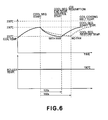
Embodiment 1. - Figure 6 is a time chart schematically showing a conventional cooling sequence.
- Figure 7 is a time chart schematically showing a cooling sequence in
Embodiment 1. - Figure 8 is a time chart in the case where a fixation roller is not rotated in
Embodiment 1. - Figure 9 is a time chart schematically showing a cooling sequence in Embodiment 3.
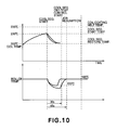
- Figure 10 is a time chart schematically showing a cooling sequence in
Embodiment 5. - Figures 11(a) and 11(b) are schematic views each showing a magnetic flux shielding means in Embodiment 6.
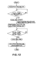
- Figure 12 is a flow chart schematically showing a cooling operation.
- Figure 4 is a schematic sectional view of an induction heating apparatus in this embodiment of the present invention. Incidentally, a constitution of an electrophotographic apparatus including the induction heating apparatus as a fixation apparatus is the same as that described above with reference to Figure 2 except that the constitution of the fixation apparatus is different, thus being omitted from specific explanation.
- Referring to Figure 4, a
fixation roller 8 as a heat rotation member which generates heat by electromagnetic induction comprises an iron-made core metal cylinder having an outer diameter of 40 mm, a thickness of 0.7 mm, and a length of 340 mm and a surface layer of a fluorine-containing resin, such as PFA or PTFE, for improving a surface releasability. In order to obtain a high-quality fixation image such as a color image, between the core metal cylinder and the surface layer, it is also possible to dispose a heat-resistant elastic layer of silicone rubber or the like. - A
pressure roller 9 as a nip forming member is constituted by a hollow core metal having an outer diameter of 35 mm, a thickness of 3 mm, and a length of 340 mm, and a heat insulating layer which is formed as a heat-resistant rubber layer having a surface releasability at a peripheral surface of the core metal. - The
fixation roller 8 and thepressure roller 9 are rotatably supported and pressed against each other by an unshown pressure mechanism, thus forming a fixation nip N having a width of about 5 mm. Thefixation roller 8 is driven at a speed of 300 mm/sec by an unshown rotation motor, and thepressure roller 9 is rotated by a frictional force with thefixation roller 8 at the fixation nip N. A recording sheet P is introduced in the fixation nip N while carrying thereon unfixed toner image t, and the toner image t is heated under pressure to become a fixed image. - An
induction coil 13 is held by a core 12 (12a, 12b) in an unshown holder formed of a heat-resistant magnetic resin, such as PPS, PEEK, phenolic resin, etc., and by a stay (not shown). To theinduction coil 13, an AC current of 10 - 100 kHz is applied, whereby an eddy current is generated at an inner surface, which is an electroconductive layer, of thefixation roller 8 by a magnetic field induced by the AC current, thus generating Joule heat. At this time, the induction coil per se also generates heat by an internal resistance thereof. - Now, assuming that a temperature-controlled state in which a surface temperature of the fixation roller is kept at a normal fixing temperature of 200 °C by a temperature detection means 11 when paper having a A4 size which is a maximum width of plain paper in an axial direction of the fixation roller is continuously passed through the fixation nip is continued for 1 hour, this state is such a state that the temperature of the induction coil in the fixation roller at its central portion is predicted that it reaches 230 °C on the basis of previous study as shown in Figure 5. A coating resin of the induction coil is formed of a material which is melted at 235 °C, so that there is a possibility that the induction coil becomes electrically shorted.
- For this reason, in the present invention, in the case where such a temperature rise of the induction coil is caused to occur although the temperature of the fixation roller is kept at a normal fixing temperature, an image forming job is interrupted and a cooling sequence of the induction coil as shown in Figure 12 is executed. Incidentally, Figure 1 is a time-line chart showing progressions of a induction coil temperature and a fixation roller temperature with time in a pre-stage of the cooling sequence, in an execution stage of the cooling sequence, and after completion of the cooling sequence. Figure 1 also shows progressions of energization of the induction coil a rotation speed of the fixation roller, a position of a magnetic flux shielding plate, a nip pressure between the fixation roller and the pressure roller, and the cooling sequence.
- In the cooling sequence, when the temperature of the induction coil reaches 230 °C (predetermined temperature) (or is predicted that it reaches 230 °C), the image forming job is temporarily stopped and power supply to the induction coil by a control apparatus (energization control means) 100 is turned off. In this state, the cooling sequence is started by rotating the
fixation roller 8 and thepressure roller 9 by using a rotation control means 16. - In the cooling sequence, the power supply to the induction coil is turned off, so that there is no heat generation due to the internal resistance of the induction coil. Further, by idle rotation of the fixation roller, a high-temperature ambient air between the fixation roller and the induction coil is dissipated outside the fixation roller.
- Further, the fixation roller is rotated at idle in contact with the pressure roller, so that the heat of the fixation roller is also released into the pressure roller. This is because the pressure roller is not provided with a heat source, thus having a lower temperature. Further, by the idle rotation of the fixation roller, the heat is also released into ambient air. As described above, the cooling sequence has two cooling functions.
- By the above described cooling sequence, the induction coil temperature is lowered to a restore set temperature of 200 °C. A time required to resume the sheet passing operation was about 180 sec as shown in Figure 6 in the case where both of the fixation roller and the pressure roller are rotated while temperature-controlling the fixation roller so as to be kept at a certain temperature by a conventional temperature detection means 11. Further, in the case of using a fan, the time was 120 sec. When the induction heating is stopped without rotating the fixation roller, as shown in Figure 8, the induction coil temperature is gradually lowered but an irregularity in temperature particularly between the fixation nip portion and another (non-nip) portion (e.g., at a lowest temperature position) is caused to occur, so that irregularities in fixability and gloss are caused to occur if left uncontrolled. Further, the fixation roller is not rotated, so that an amount of heat released into air is also decreased. For this reason, the above described time which also including a time required for removal of the irregularities is 130 sec for resumption of the sheet passing operation. Here, the induction coil temperature is measured by disposing a thermocouple in the neighborhood of the induction coil.
- Compared with the above described conventional cooling sequence, in the cooling sequence in the present invention, as shown in Figure 7, the time for the resumption is 75 sec without using a particular cooling mechanism. In the case of using a fan in combination, it is possible to resume the sheet passing operation (image forming operation) in 30 sec.
- In this embodiment, the temperature of induction coil is predicted by the temperature detection means of the fixation roller and the continuous energization time of the induction coil but may also be predicted by other conditions or be directly detected to performed the cooling sequence. Incidentally, the continuous energization time is measured by a timer provided in the control apparatus.
- The continuous energization time of the induction coil refers to a time period during which energization of the induction coil is continued when a plurality of recording sheets are continuously subjected to image formation. Incidentally, in such a constitution that the energization of the induction coil is on-off controlled depending on a detected temperature of the fixation roller, counting of the energization time is not stopped by "energization off" but is continued as it is.
- In this embodiment, a basic constitution is the same as in
Embodiment 1 except that the fixation apparatus further includes a magnetic flux shielding means which can be disposed between the induction coil and the fixation roller to shield generated magnetic flux at both end portions of the fixation roller in its axial direction. More specifically, as shown in Figure 4, by a magnetic flux shielding means drive means 15, the magnetic flux shielding means is moved, in a circumferential direction of the fixation roller, to aposition 14b as needed and aposition 14a if it is not required. - Now, when a sheet passing operation job of B5-sized paper which has a smaller size in a longitudinal direction of the fixation roller is selected by a user, the magnetic flux shielding means is disposed between the induction coil and the fixation roller as a heat generation member at the longitudinal end portions of the fixation roller. As a result, the fixation roller does not substantially generate heat at the both end portions thereof. WIth respect to the induction coil, an effective length of the fixation roller is decreased, so that an electrical resistance of the fixation roller is lowered, thus reducing a power factor. Accordingly, due to a reduced heat conversion efficiency, in the case where the surface of the fixation roller is used and temperature-controlled at the same temperature, the induction coil is liable to be increased in temperature by disposing the magnetic flux shielding means between the induction coil and the fixation roller.
- After a lapse of 5 minutes from the start of magnetic flux shielding, the temperature of the induction coil reaches 230 °C on the basis of previous study, so that the cooling sequence is performed to cool the induction coil and then the job is resumed. The job is completed without causing melting of the coating layer of the induction coil.
- In this embodiment, a basic constitution is the same as in
Embodiment 1 except that the fixation roller is rotationally driven at a speed of 200 mm/sec. In the case where thin paper having a smaller thickness than plain paper is used, the induction coil temperature is saturated at 220 °C, so that the constitution in this embodiment does not require the cooling sequence. - Now, when a sheet passing operation job of thick paper thicker than plain paper is selected by a user, as shown in Figure 9, a fixation temperature of the fixation roller is set to 210 °C in order to ensure a fixability of the thick paper. Further, the thick paper has a heat capacity larger than the plain paper. For these two reasons, a power supplied to the induction coil during the job of the thick paper is increased compared with the case of the job of the plain paper, so that the induction coil is liable to be increased in temperature.
- According to previous study, the induction coil temperature reaches 230 °C after a lapse of 4 minutes from the start of the job of the thick paper. Accordingly, the image forming job is interrupted after 4 minutes from the start of the job of the thick paper and the cooling sequence is performed. After the induction coil is cooled by the cooling sequence, the image forming job is resumed. As a result, the image forming job was capable of being completed to the end without causing melting of the coating resin of the induction coil. (Embodiment 4)
- In this embodiment, a basic constitution is the same as
Embodiment 1 except that the fixation roller has three rotation speeds including a speed (V1) of 300 mm/s during an ordinary white/black job, a speed (V2) of 75 mm/s during a full-color job, and a speed (V3) of 50 mm/s for suppressing heat dissipation in standby state during the sheet passing operation, and that a pressure of the fixation roller with respect to the pressure roller can be changed into three levels including no pressure (P0) for decreasing a start-up time of the fixation roller, a pressure (P1) for the plain paper job, and a pressure (P2) for meeting a job of a recording material on which it is difficult to fix a toner image. These pressures satisfy the following relationships: P0 < P1 < P2. In this case, corresponding nip widths are 1 mm, 5 mm and 7 mm, respectively. - Now, the selected job is the full-color job for plain paper and the fixation roller is set to have the rotation speed (V2) and the pressure (P1). Under these conditions, the fixation roller is placed, during the sheet passing operation, in such a state that the induction coil temperature reaches 230 °C for some reason. In this state, the rotation speed of the fixation roller is changed to the fastest rotation speed (V1) and as shown in Figure 1, the pressure of the fixation roller is changed to the largest pressure (P2) at the nip width of 7 mm to perform the cooling sequence. As described above, an amount of heat released into air and the pressure roller is increased by increasing the rotation speed of the fixation roller and the amount of heat released into the pressure roller is further increased by increasing the nip width, so that the time required for resumption of the job was capable of being described from 40 sec under the conditions of V2 and P1 to 25 sec under the conditions of V1 and P2.
- In this embodiment, a basic constitution is the same as in Embodiment 2 except that the position of the magnetic flux shielding means is changed.
- More specifically, a job of a small-sized paper is selected and as shown in Figure 10, the fixation roller is placed in such a state that the induction coil temperature reaches 230 °C when the magnetic flux shielding (adjusting) means is located at the
position 14b. In this case, the magnetic flux shielding means is spaced apart from the induction coil and moved to theposition 14a and at the same time, the cooling sequence is performed. The magnetic flux shielding means per se is also increased in temperature, so that the time required to resume the job is decreased from 35 sec at theposition 14b to 30 sec at theposition 14a because an amount of heat released into the induction coil can be reduced by moving the magnetic flux shielding means to theposition 14a. - Alternatively, a time period during which the magnetic flux shielding (adjusting) means is located at the magnetic flux shielding position is counted by a
CPU 101 and the induction coil temperature is judged that it reaches a predetermined temperature when the time period exceeds a predetermined time period. When this judgement is made, the cooling sequence may be performed. - In this embodiment, a basic constitution is the same as in Embodiment 2 except that the shape of the magnetic flux shielding means is changed to those shown in Figures 11(a) and 11(b). More specifically, the magnetic flux shielding means is designed so that it can shield magnetic flux at both end portions thereof at two stages in order to meet papers of various sizes.
- Now, a job of 05-sized paper is selected by a user. In the case where the magnetic flux shielding means is a one-stage shielding plate (member) for shielding the magnetic flux over a length corresponding to an intermediary length between those of A4 (short side) and B5 (long side), temperature rise at end portions of the fixation roller is caused to occur at non-sheet passing portion. For this reason, the magnetic flux shielding means is required to be disposed at the magnetic flux shielding position. In this case, when the magnetic flux shielding is effected, end portions of the B5-sized paper in the axial direction is rather less liable to generate heat. As a result, it is difficult to effect fixation at the non-heating area. In addition, the magnetic flux is excessively shielded, so that the temperature rise of the induction coil is more liable to occur. However, when a two-stage shielding plate (member) which meets the respective sized papers of A4 (short side) and B5 (long side) as shown in Figure 11(b) is used, a
coil center core 12b shown in FIgure 4 is shielded at a position shown in Figure 11(b). As a result, magnetic flux at only a necessary portion can be shielded, so that the temperature rise of the induction coil can be considerably suppressed. Accordingly, the number of execution of the cooling sequence can be decreased. More specifically, with respect to type one-stage shielding plate, the number of execution of the cooling sequence is 4 in a job for 1000 sheets. On the other hand, with respect to the two-stage shielding plate, the number of execution of the cooling sequence is decreased to 2, so that the job for 1000 sheets was capable of being completed about 1 minute higher than the case of the one-stage shielding plate. - As described hereinabove, according to the present invention, it is possible to efficiently effect cooling of the induction coil with a simple constitution.
- While the invention has been described with reference to the structures disclosed herein, it is not confined to the details set forth and this application is intended to cover such modifications or changes as may come within the purpose of the improvements or the scope of the following claims.
- In a fixation apparatus using induction heating, a cooling sequence is performed, after an output of a magnetic flux generation member is terminated, to quickly effect cooling of an induction coil when needed without disposing a particular member.
Claims (9)
- An image heating apparatus, comprising:a heat rotation member for heating an image on a recording material;an induction coil for causing said heat rotation member to generate heat by induction heating;control means for controlling a temperature of said heat rotation member by regulating energization of said induction coil; andexecution means for executing a cooling operation for said induction coil, when said induction coil is increased in temperature beyond a predetermined level by the energization of said induction coil despite the temperature of said heat rotation member being normal, by stopping an image heating operation and rotating said heat rotation member.
- An apparatus according to Claim 1, wherein said execution means executes the cooling operation when a continuous energization time of said induction coil is a predetermined time.
- An apparatus according to Claim 1, said apparatus further comprises magnetic flux adjusting member for adjusting magnetic flux, generated from said induction coil, acting on said heat rotation member; and said execution means executes the cooling operation when a time of continuous presence of said magnetic flux adjusting member at a magnetic flux adjusting position is a predetermined time.
- An apparatus according to Claim 3, wherein said execution means executes the cooling operation in a state in which said magnetic flux adjusting member is moved from the magnetic flux adjusting position to a position spaced apart from the magnetic flux adjusting position.
- An apparatus according to Claim 1, wherein said apparatus further comprises a nip forming member for forming a heat nip between said nip forming member and said heat rotation member, and a width of the heat nip during the cooling operation is longer than that during an ordinary image heat treatment.
- An apparatus according to Claim 1, wherein said apparatus further comprises a nip forming member for forming a heat nip between said nip forming member and said heat rotation member, and a pressure of the heat nip during the cooling operation is larger than that during an ordinary image heat treatment.
- An apparatus according to Claim 1, wherein said induction coil is disposed inside said heat rotation member.
- An image heating apparatus, comprising:a heat rotation member for heating an image on a recording material;an induction coil for causing said heat rotation member to generate heat by induction heating;control means for controlling a temperature of said heat rotation member by regulating energization of said induction coil;temperature detection means for detecting a temperature of said induction coil; andexecution means for executing a cooling operation for said induction coil, when the detected temperature of said induction coil reaches a predetermined temperature.
- An apparatus according to Claim 8, wherein said execution means executes the cooling operation for said induction coil despite the temperature of said heat rotation member being normal by stopping an image heating operation.
Applications Claiming Priority (1)
| Application Number | Priority Date | Filing Date | Title |
|---|---|---|---|
| JP2004308336A JP4652769B2 (en) | 2004-10-22 | 2004-10-22 | Induction heating fixing device |
Publications (2)
| Publication Number | Publication Date |
|---|---|
| EP1650610A1 true EP1650610A1 (en) | 2006-04-26 |
| EP1650610B1 EP1650610B1 (en) | 2012-03-07 |
Family
ID=35613646
Family Applications (1)
| Application Number | Title | Priority Date | Filing Date |
|---|---|---|---|
| EP05023038A Expired - Lifetime EP1650610B1 (en) | 2004-10-22 | 2005-10-21 | Control of cooling in induction image heating apparatus |
Country Status (5)
| Country | Link |
|---|---|
| US (1) | US20060086720A1 (en) |
| EP (1) | EP1650610B1 (en) |
| JP (1) | JP4652769B2 (en) |
| KR (1) | KR100762855B1 (en) |
| CN (1) | CN1763648B (en) |
Families Citing this family (11)
| Publication number | Priority date | Publication date | Assignee | Title |
|---|---|---|---|---|
| US7238924B2 (en) * | 2004-10-22 | 2007-07-03 | Canon Kabushiki Kaisha | Magnetic flux image heating apparatus with control of movement of magnetic flux shield |
| DE602005014838D1 (en) | 2004-10-22 | 2009-07-23 | Canon Kk | Temperature control in induction image heating device with magnetic flux adjustment element |
| JP4208815B2 (en) * | 2004-10-22 | 2009-01-14 | キヤノン株式会社 | Image heating device |
| CN100444049C (en) | 2004-10-22 | 2008-12-17 | 佳能株式会社 | image forming device |
| JP4208816B2 (en) | 2004-10-22 | 2009-01-14 | キヤノン株式会社 | Image heating device |
| JP4731982B2 (en) * | 2005-04-28 | 2011-07-27 | キヤノン株式会社 | Image heating device |
| JP4756967B2 (en) * | 2005-09-14 | 2011-08-24 | キヤノン株式会社 | Image heating device |
| JP4498407B2 (en) | 2006-12-22 | 2010-07-07 | キヤノン株式会社 | Process cartridge, electrophotographic image forming apparatus, and electrophotographic photosensitive drum unit |
| JP2010019906A (en) * | 2008-07-08 | 2010-01-28 | Ricoh Co Ltd | Fixing device and image forming apparatus |
| JP6052598B2 (en) * | 2012-01-30 | 2016-12-27 | 株式会社リコー | Fixing apparatus and image forming apparatus |
| US11701800B2 (en) * | 2019-01-04 | 2023-07-18 | Roller Labz, LLC | Systems and methods for reconditioning polymeric wheels |
Citations (7)
| Publication number | Priority date | Publication date | Assignee | Title |
|---|---|---|---|---|
| JPH10161446A (en) * | 1996-11-29 | 1998-06-19 | Ricoh Co Ltd | Induction heating roller |
| JPH10307514A (en) | 1997-05-02 | 1998-11-17 | Ricoh Co Ltd | Image forming device |
| JP2001307862A (en) | 2000-04-21 | 2001-11-02 | Canon Inc | Heating device and image forming device |
| US6347201B1 (en) * | 1999-07-23 | 2002-02-12 | Canon Kabushiki Kaisha | Image heating apparatus |
| JP2004171013A (en) | 2004-01-13 | 2004-06-17 | Ricoh Co Ltd | Fixing device |
| JP2004265670A (en) * | 2003-02-28 | 2004-09-24 | Canon Inc | Heating equipment |
| JP2004272157A (en) * | 2003-03-12 | 2004-09-30 | Canon Inc | Image heating device |
Family Cites Families (13)
| Publication number | Priority date | Publication date | Assignee | Title |
|---|---|---|---|---|
| JPH04235583A (en) * | 1991-01-11 | 1992-08-24 | Toshiba Corp | Temperature controller |
| DE69217436T2 (en) * | 1991-09-24 | 1997-07-10 | Canon Kk | Image heater with multiple temperature detectors |
| JPH08146616A (en) * | 1994-11-18 | 1996-06-07 | Konica Corp | Drum type transfer device |
| JPH08146803A (en) * | 1994-11-24 | 1996-06-07 | Mita Ind Co Ltd | Fixing device |
| GB2319583B (en) * | 1996-11-25 | 1999-09-22 | Ricoh Kk | Device with induction heating roller |
| JP4319299B2 (en) * | 1999-09-24 | 2009-08-26 | 東芝テック株式会社 | Image forming apparatus and fixing device |
| JP2002056960A (en) * | 2000-08-08 | 2002-02-22 | Canon Inc | Heating device and image forming device |
| JP2002083676A (en) * | 2000-09-08 | 2002-03-22 | Canon Inc | Heating device and image forming device |
| US6643476B1 (en) * | 2000-10-31 | 2003-11-04 | Kabushiki Kaisha Toshiba | Image forming apparatus with accurate temperature control for various media having different thickness |
| JP3737049B2 (en) * | 2001-03-30 | 2006-01-18 | シャープ株式会社 | Heating apparatus and image forming apparatus using the same |
| JP3880334B2 (en) * | 2001-05-28 | 2007-02-14 | キヤノン株式会社 | Image heating apparatus and image forming apparatus |
| JP2004126103A (en) * | 2002-10-01 | 2004-04-22 | Canon Inc | Fixing device and image forming device |
| JP4110046B2 (en) * | 2003-06-10 | 2008-07-02 | キヤノン株式会社 | Image heating device |
-
2004
- 2004-10-22 JP JP2004308336A patent/JP4652769B2/en not_active Expired - Fee Related
-
2005
- 2005-10-21 US US11/254,718 patent/US20060086720A1/en not_active Abandoned
- 2005-10-21 EP EP05023038A patent/EP1650610B1/en not_active Expired - Lifetime
- 2005-10-21 KR KR1020050099424A patent/KR100762855B1/en not_active Expired - Fee Related
- 2005-10-21 CN CN2005101163670A patent/CN1763648B/en not_active Expired - Fee Related
Patent Citations (7)
| Publication number | Priority date | Publication date | Assignee | Title |
|---|---|---|---|---|
| JPH10161446A (en) * | 1996-11-29 | 1998-06-19 | Ricoh Co Ltd | Induction heating roller |
| JPH10307514A (en) | 1997-05-02 | 1998-11-17 | Ricoh Co Ltd | Image forming device |
| US6347201B1 (en) * | 1999-07-23 | 2002-02-12 | Canon Kabushiki Kaisha | Image heating apparatus |
| JP2001307862A (en) | 2000-04-21 | 2001-11-02 | Canon Inc | Heating device and image forming device |
| JP2004265670A (en) * | 2003-02-28 | 2004-09-24 | Canon Inc | Heating equipment |
| JP2004272157A (en) * | 2003-03-12 | 2004-09-30 | Canon Inc | Image heating device |
| JP2004171013A (en) | 2004-01-13 | 2004-06-17 | Ricoh Co Ltd | Fixing device |
Non-Patent Citations (3)
| Title |
|---|
| PATENT ABSTRACTS OF JAPAN vol. 1998, no. 11 30 September 1998 (1998-09-30) * |
| PATENT ABSTRACTS OF JAPAN vol. 2002, no. 03 3 April 2002 (2002-04-03) * |
| PATENT ABSTRACTS OF JAPAN vol. 2003, no. 12 5 December 2003 (2003-12-05) * |
Also Published As
| Publication number | Publication date |
|---|---|
| JP2006119455A (en) | 2006-05-11 |
| KR20060049113A (en) | 2006-05-18 |
| US20060086720A1 (en) | 2006-04-27 |
| CN1763648A (en) | 2006-04-26 |
| CN1763648B (en) | 2010-07-14 |
| KR100762855B1 (en) | 2007-10-02 |
| EP1650610B1 (en) | 2012-03-07 |
| JP4652769B2 (en) | 2011-03-16 |
Similar Documents
| Publication | Publication Date | Title |
|---|---|---|
| JP3527442B2 (en) | Image heating device and image forming device | |
| JP4163993B2 (en) | Heating device and driving method of heating device | |
| US8606160B2 (en) | Image heating apparatus heating a toner image on a sheet by the magnetic flux from an excitation coil and controlling the electric power supply to the coil | |
| JPH07295414A (en) | Fixing device of image formation device | |
| JP2000221830A (en) | Fixing device and image forming device | |
| US20060157475A1 (en) | Image heating apparatus having a heat generation member generating heat by magnetic flux and heating an image on a recording material | |
| JP5518238B2 (en) | Image heating device | |
| EP1650610B1 (en) | Control of cooling in induction image heating apparatus | |
| JP4047644B2 (en) | Fixing device | |
| US6882808B2 (en) | Fixing device and control method therefor | |
| JP2005121899A (en) | Fixing apparatus and image forming apparatus | |
| JPWO2001048559A1 (en) | Image forming apparatus and fixing device | |
| JP2001203072A (en) | Heating device, image heating device and image forming device | |
| US20060289482A1 (en) | Image heating apparatus | |
| JP2004272157A (en) | Image heating device | |
| JPH07114294A (en) | Fixing device | |
| JPH07253731A (en) | Heating device and image forming apparatus | |
| JP4353120B2 (en) | Fixing device | |
| JP4585700B2 (en) | Image forming apparatus | |
| JPH11167307A (en) | Image forming device | |
| JP2006267180A (en) | Fixing device and image forming apparatus | |
| JP2001102163A (en) | Heating device, image heating device and image forming device | |
| JP2000321903A (en) | Induction heating type fixing device | |
| JP2004333621A (en) | Heating equipment | |
| JP2002116644A (en) | Heat fixing-device and image forming device |
Legal Events
| Date | Code | Title | Description |
|---|---|---|---|
| PUAI | Public reference made under article 153(3) epc to a published international application that has entered the european phase |
Free format text: ORIGINAL CODE: 0009012 |
|
| 17P | Request for examination filed |
Effective date: 20051021 |
|
| AK | Designated contracting states |
Kind code of ref document: A1 Designated state(s): AT BE BG CH CY CZ DE DK EE ES FI FR GB GR HU IE IS IT LI LT LU LV MC NL PL PT RO SE SI SK TR |
|
| AX | Request for extension of the european patent |
Extension state: AL BA HR MK YU |
|
| AKX | Designation fees paid |
Designated state(s): DE FR GB |
|
| GRAP | Despatch of communication of intention to grant a patent |
Free format text: ORIGINAL CODE: EPIDOSNIGR1 |
|
| GRAS | Grant fee paid |
Free format text: ORIGINAL CODE: EPIDOSNIGR3 |
|
| GRAA | (expected) grant |
Free format text: ORIGINAL CODE: 0009210 |
|
| AK | Designated contracting states |
Kind code of ref document: B1 Designated state(s): DE FR GB |
|
| REG | Reference to a national code |
Ref country code: GB Ref legal event code: FG4D |
|
| REG | Reference to a national code |
Ref country code: DE Ref legal event code: R096 Ref document number: 602005032991 Country of ref document: DE Effective date: 20120503 |
|
| PLBE | No opposition filed within time limit |
Free format text: ORIGINAL CODE: 0009261 |
|
| STAA | Information on the status of an ep patent application or granted ep patent |
Free format text: STATUS: NO OPPOSITION FILED WITHIN TIME LIMIT |
|
| 26N | No opposition filed |
Effective date: 20121210 |
|
| REG | Reference to a national code |
Ref country code: DE Ref legal event code: R097 Ref document number: 602005032991 Country of ref document: DE Effective date: 20121210 |
|
| GBPC | Gb: european patent ceased through non-payment of renewal fee |
Effective date: 20121021 |
|
| REG | Reference to a national code |
Ref country code: FR Ref legal event code: ST Effective date: 20130628 |
|
| PG25 | Lapsed in a contracting state [announced via postgrant information from national office to epo] |
Ref country code: GB Free format text: LAPSE BECAUSE OF NON-PAYMENT OF DUE FEES Effective date: 20121021 |
|
| PG25 | Lapsed in a contracting state [announced via postgrant information from national office to epo] |
Ref country code: FR Free format text: LAPSE BECAUSE OF NON-PAYMENT OF DUE FEES Effective date: 20121031 |
|
| PGFP | Annual fee paid to national office [announced via postgrant information from national office to epo] |
Ref country code: DE Payment date: 20141031 Year of fee payment: 10 |
|
| REG | Reference to a national code |
Ref country code: DE Ref legal event code: R119 Ref document number: 602005032991 Country of ref document: DE |
|
| PG25 | Lapsed in a contracting state [announced via postgrant information from national office to epo] |
Ref country code: DE Free format text: LAPSE BECAUSE OF NON-PAYMENT OF DUE FEES Effective date: 20160503 |