EP1650406A2 - Locking assembly for a gas turbine rotor stage - Google Patents
Locking assembly for a gas turbine rotor stage Download PDFInfo
- Publication number
- EP1650406A2 EP1650406A2 EP04257439A EP04257439A EP1650406A2 EP 1650406 A2 EP1650406 A2 EP 1650406A2 EP 04257439 A EP04257439 A EP 04257439A EP 04257439 A EP04257439 A EP 04257439A EP 1650406 A2 EP1650406 A2 EP 1650406A2
- Authority
- EP
- European Patent Office
- Prior art keywords
- plate
- locking
- disc
- retaining plate
- locking assembly
- Prior art date
- Legal status (The legal status is an assumption and is not a legal conclusion. Google has not performed a legal analysis and makes no representation as to the accuracy of the status listed.)
- Granted
Links
- 238000011144 upstream manufacturing Methods 0.000 claims abstract description 12
- 238000000034 method Methods 0.000 claims description 8
- 238000005452 bending Methods 0.000 claims description 6
- 238000002485 combustion reaction Methods 0.000 description 3
- 230000001141 propulsive effect Effects 0.000 description 3
- 230000001133 acceleration Effects 0.000 description 1
- 239000002131 composite material Substances 0.000 description 1
- 230000006835 compression Effects 0.000 description 1
- 238000007906 compression Methods 0.000 description 1
- 230000008602 contraction Effects 0.000 description 1
- 238000005336 cracking Methods 0.000 description 1
- 239000000446 fuel Substances 0.000 description 1
- 230000005484 gravity Effects 0.000 description 1
- 239000000463 material Substances 0.000 description 1
- 239000000203 mixture Substances 0.000 description 1
- 230000000717 retained effect Effects 0.000 description 1
- 238000007493 shaping process Methods 0.000 description 1
- XLYOFNOQVPJJNP-UHFFFAOYSA-N water Substances O XLYOFNOQVPJJNP-UHFFFAOYSA-N 0.000 description 1
Images


Classifications
-
- F—MECHANICAL ENGINEERING; LIGHTING; HEATING; WEAPONS; BLASTING
- F01—MACHINES OR ENGINES IN GENERAL; ENGINE PLANTS IN GENERAL; STEAM ENGINES
- F01D—NON-POSITIVE DISPLACEMENT MACHINES OR ENGINES, e.g. STEAM TURBINES
- F01D5/00—Blades; Blade-carrying members; Heating, heat-insulating, cooling or antivibration means on the blades or the members
- F01D5/30—Fixing blades to rotors; Blade roots ; Blade spacers
- F01D5/32—Locking, e.g. by final locking blades or keys
- F01D5/326—Locking of axial insertion type blades by other means
-
- F—MECHANICAL ENGINEERING; LIGHTING; HEATING; WEAPONS; BLASTING
- F01—MACHINES OR ENGINES IN GENERAL; ENGINE PLANTS IN GENERAL; STEAM ENGINES
- F01D—NON-POSITIVE DISPLACEMENT MACHINES OR ENGINES, e.g. STEAM TURBINES
- F01D5/00—Blades; Blade-carrying members; Heating, heat-insulating, cooling or antivibration means on the blades or the members
- F01D5/30—Fixing blades to rotors; Blade roots ; Blade spacers
- F01D5/3007—Fixing blades to rotors; Blade roots ; Blade spacers of axial insertion type
- F01D5/3015—Fixing blades to rotors; Blade roots ; Blade spacers of axial insertion type with side plates
-
- F—MECHANICAL ENGINEERING; LIGHTING; HEATING; WEAPONS; BLASTING
- F05—INDEXING SCHEMES RELATING TO ENGINES OR PUMPS IN VARIOUS SUBCLASSES OF CLASSES F01-F04
- F05D—INDEXING SCHEME FOR ASPECTS RELATING TO NON-POSITIVE-DISPLACEMENT MACHINES OR ENGINES, GAS-TURBINES OR JET-PROPULSION PLANTS
- F05D2250/00—Geometry
- F05D2250/60—Structure; Surface texture
- F05D2250/61—Structure; Surface texture corrugated
-
- F—MECHANICAL ENGINEERING; LIGHTING; HEATING; WEAPONS; BLASTING
- F05—INDEXING SCHEMES RELATING TO ENGINES OR PUMPS IN VARIOUS SUBCLASSES OF CLASSES F01-F04
- F05D—INDEXING SCHEME FOR ASPECTS RELATING TO NON-POSITIVE-DISPLACEMENT MACHINES OR ENGINES, GAS-TURBINES OR JET-PROPULSION PLANTS
- F05D2250/00—Geometry
- F05D2250/70—Shape
- F05D2250/75—Shape given by its similarity to a letter, e.g. T-shaped
-
- F—MECHANICAL ENGINEERING; LIGHTING; HEATING; WEAPONS; BLASTING
- F05—INDEXING SCHEMES RELATING TO ENGINES OR PUMPS IN VARIOUS SUBCLASSES OF CLASSES F01-F04
- F05D—INDEXING SCHEME FOR ASPECTS RELATING TO NON-POSITIVE-DISPLACEMENT MACHINES OR ENGINES, GAS-TURBINES OR JET-PROPULSION PLANTS
- F05D2260/00—Function
- F05D2260/30—Retaining components in desired mutual position
- F05D2260/33—Retaining components in desired mutual position with a bayonet coupling
-
- F—MECHANICAL ENGINEERING; LIGHTING; HEATING; WEAPONS; BLASTING
- F05—INDEXING SCHEMES RELATING TO ENGINES OR PUMPS IN VARIOUS SUBCLASSES OF CLASSES F01-F04
- F05D—INDEXING SCHEME FOR ASPECTS RELATING TO NON-POSITIVE-DISPLACEMENT MACHINES OR ENGINES, GAS-TURBINES OR JET-PROPULSION PLANTS
- F05D2260/00—Function
- F05D2260/30—Retaining components in desired mutual position
- F05D2260/38—Retaining components in desired mutual position by a spring, i.e. spring loaded or biased towards a certain position
Definitions
- the present invention relates to apparatus for securing and retaining components of a rotor assembly in a turbine engine.
- annular array of blades is radially retained, via cooperating dovetail or fir-tree features, to a rotor disc. It is desirable to provide an annular seal plate to at least the downstream face of the rotor to axially retain the blades.
- the seal plate also provides a seal to prevent or limit undesirable gas leakage passing therethrough.
- US4019833 discloses such a retaining plate and rotor disc, each comprising a cooperating annular array of interlocking bayonet features that hold the retaining ring to the rotor disc. The blades engage with the plate to prevent its rotation with respect to the disc and consequent undesirable disconnection.
- the blades are not used for locking the plate as the blades are critical components and any damage caused could compromise their integrity and that of the engine. Furthermore, this prior art arrangement necessitates the fitting of a front retaining plate last and such fitting is difficult and time consuming.
- US5622475 recites the use of a split-locking ring to secure an annular retaining plate.
- the split-locking ring which contacts the disc and the retaining plate, is prone to movement during engine operation and causes fretting against the contact surfaces thus reducing the life of the parts. In certain circumstance, this fretting could initiate undesirable cracking.
- This arrangement is further disadvantaged in that a full annular locking ring incurs a significant weight penalty, particularly considering it is part of a high-speed rotating assembly.
- the Trent 500 aero-engine of Rolls-Royce plc which entered into service August 2002, comprised a bayoneted retaining ring and a number of locking plugs as shown in Figure 2.
- the locking plugs are inserted between castellations on the disc and a retaining plate to prevent relative rotation therebetween.
- a wire is used to secure the locking plugs in place.
- the wire is prone to failure partly due to high centrifugal forces and high temperatures.
- a locking assembly for a rotor stage of a gas turbine engine, the rotor stage comprising an annular array of radially extending blades secured to a rotor disc via an attachment and an annular retaining plate capable of preventing axial movement of the blades, the retaining plate is secured to an axial face of the disc via a bayonet arrangement, the bayonet arrangement comprising engagable and complimentary castellations on the disc and lands on the retaining plate, characterised in that the locking assembly comprises a locking plug having an arm and a leg part and when assembled the arm engages upstream of a radially inner region of the retaining plate and the leg part is configured to span between and abut both circumferentially adjacent castellations and lands, thereby preventing relative rotation between the disc and the retaining plate.
- the locking plug is configured in a generally Y-shaped cross section having a channel portion defined by arms and the leg part and when assembled the arms engage upstream and downstream of a radially inner region of the retaining plate.
- the assembly comprises a securing plate, the securing plate configured to span between circumferentially adjacent castellations thereby preventing the locking plug from disengaging the disc and retaining plate.
- the securing plate extends across a gap between castellations and is captured at each end within recesses defined in the disc.
- the securing plate is longer than the gap between recesses such that the locking plate cannot be completely flattened against the locking plug.
- the securing plate is configured to provided a biasing force to urge its ends into the recesses.
- the securing plate is formed in any one of the group comprising a W-, V- or U-shape.
- a gap is defined between the securing plate and the locking plug.
- a method of assembling a rotor stage comprising the locking assembly as claimed in claim 3 comprising the steps of; inserting the locking plug to engage the circumferentially adjacent castellations and lands thereby preventing relative rotation between the disc and the retaining plate, presenting a securing plate in a first bent form so that each end of the plate is presented near to the recesses, and flattening the plate so that the projections engage the recesses thereby preventing the securing plate and importantly the locking plug from falling out during use.
- a method of disassembling a rotor stage comprising the locking assembly as claimed in claim 3 comprising the steps of; bending the flattened plate so that the projections disengage the recesses and remove the plate, removing the locking plug from engagement with the circumferentially adjacent castellations and lands.
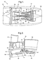
- a ducted fan gas turbine engine generally indicated at 10 has a principal and rotational axis 11.
- the engine 10 comprises, in axial flow series, an air intake 12, a propulsive fan 13, an intermediate pressure compressor 14, a high-pressure compressor 15, combustion equipment 16, a high-pressure turbine 17, and intermediate pressure turbine 18, a low-pressure turbine 19 and a core exhaust nozzle 20.
- a nacelle 21 generally surrounds the engine 10 and defines both the intake 12 and a final exhaust nozzle 22.
- the gas turbine engine 10 works in the conventional manner so that air entering the intake 11 is accelerated by the fan 13 to produce two air flows: a first air flow into the intermediate pressure compressor 14 and a second air flow which passes through a bypass duct 23 to provide propulsive thrust.
- the intermediate pressure compressor 14 compresses the air flow directed into it before delivering that air to the high pressure compressor 15 where further compression takes place.
- the compressed air exhausted from the high-pressure compressor 15 is directed into the combustion equipment 16 where it is mixed with fuel and the mixture combusted.
- the resultant hot combustion products then expand through, and thereby drive the high, intermediate and low-pressure turbines 17, 18, 19 before being exhausted through the nozzle 20 to provide additional propulsive thrust.
- the high, intermediate and low-pressure turbines 17, 18, 19 respectively drive the high and intermediate pressure compressors 15, 14 and the fan 13 by suitable interconnecting shafts 24, 25, 26.
- the fan 13 is circumferentially surrounded by a structural member in the form of a fan casing 28, which is supported by an annular array of outlet guide vanes 27.
- the general direction of gas flow through the engine 10 is from left to right as shown by arrow A and the terms downstream and upstream refer to this gas flow direction.
- FIG 2 shows a stage of the high-pressure turbine 17 (HPT) of a Trent 500 aeroengine of Rolls-Royce plc, which entered into service August 2002.
- the HPT 17 comprises an annular array of blades 30 (only one of which is shown), secured to a rotor disc 32 via complimentary fir-tree root 34 and slot 36 features respectively.
- From a downstream (axial) surface 66 of the disc 32 extends an annular array of castellations 40, each formed in a hook shape.
- An annular retaining plate 38 sometimes referred to as a seal plate, comprises similarly spaced lands 42 extending from a radially inner part thereof.
- This type of arrangement is commonly referred to as a bayonet arrangement 49, such that the lands 42 may engage the hooked castellations 40 on a partial rotation of the plate 38 relative to the disc 32.
- the plate 38 is prevented from axial movement in the upstream direction by the downstream surface 66 of the disc 32 and in the downstream direction by the bayonet arrangement 40, 42.
- this arrangement may be used on an upstream (axial) surface 68 of the disc 32 to prevent the blades 30 from moving upstream.
- the disc surfaces 66, 68 are substantially perpendicular to the main engine axis 11.
- a number of locking plugs 44 are inserted between castellations 40 on the disc and retaining plate 38.
- the plugs 44 abut between circumferentially adjacent lands 42 and hooks 40, thereby preventing relative rotation between the disc 32 and retaining plate 38.
- a bent wire 46 is arranged through holes defined in the plugs 44 and is looped radially inwardly and then upstream of the retaining plate 38 and between the disc 32. The wire 46 is used to secure the locking plugs 44 in place, but does not assist in preventing relative rotation of the plate 38 and disc 32 directly.
- the present invention relates to a locking assembly 48 comprising a locking plug 50 and a securing plate 52.
- the locking plug 50 is generally Y-shaped in cross section having a channel portion defined by first and second arms 56, 57 and a leg part 58.
- first and second arms 56, 57 engage upstream and downstream respectively of a radially inner region 60 of the retaining plate 38.
- leg part 58 is configured to span between and abut circumferentially adjacent castellations 40 and abut the lands 42 of the retaining plate 38. Thus the retaining plate 38 and disc 32 are prevented from relative rotation therebetween.
- the purpose of the second arm 57 is to prevent the plug 50 from "falling" upstream and contacting the disc 32, as such contact could cause undesirable fretting therebetween, and subsequently limit the service life of the disc 32.
- the purpose of the first arm 56 although mechanically redundant, is to engage the and further improve the plug's stability against flutter and frettage.
- the arm 56 also provides an increased abutment area against the castellations 40 and the lands 42 and therefore reduces wear at these positions. Where the plug 50 is adequately chocked by the securing plate 52, the first arm 56 is not included enabling the plug 50 to be lighter and cheaper to produce.
- the locking plug 50 When assembled to a rotor assembly, such as the HPT 17, the locking plug 50 is itself prevented from falling downstream and radially inwardly via the securing plate 52.
- the securing plate 52 extends across the gap between castellations 40 and is captured at each end within recesses 54 defined in the disc 32.
- the recesses 54 are defined in the castellations 40.
- the securing plate 52 is assembled from a first bent form ( Figure 4) so that projections 62 at each end of the plate 52 are presented near to the recesses 54 and then the plate 52 is flattened ( Figure 5) so that the projections 62 engage the recesses 54 thereby preventing the securing plate 52 and importantly the locking plug 50 from falling out during use.
- the length of the securing plate 52 in its flattened form is greater than the circumferential length of the gap between the castellations 40.
- this assembly 48 is capable of thermal expansion and contraction movements without compromising integrity.
- the locking plug 50 is further improved by bevelling and shaping edges and corners of the plug, particularly the arms 56 to minimise turbulence and windage.
- the leg 58 of the plug 50 is shaped to minimise weight and provide a conformal surface to the surrounding geometry 40, 42 again to minimise windage.
- the plug 50 is preferably metallic, alternatively part or all of plug 50 may be hollow or made from foamed or composite material to reduce weight whilst retaining strength.
- a channel or other feature may be formed in a surface of the leg 58 of the plug 50 or the securing plate itself.
- a chamfer 64 is formed in a lower edge of the downstream facing surface of the leg 58. This chamfer 64 forms a gap between the leg 58 and the securing plate 52 offering purchase for a tool to remove the securing plate 52.
- the securing plate 52 is formed with at least one waist 70 to enable the securing plate 52 to be bent more easily into substantially flat or slightly arcuate shape for improved removal. This is particularly useful where the plate is thickened to produce a close, aerodynamic fit profile across the bayonet gap.
- the securing plate 52 may be made slightly longer than the extent between recesses 62 such that when installed it cannot be perfectly flattened. This prevents over-bending of the plate 52 such that it is bent away from the plug 50 thereby defining a removal gap for engagement by a removal tool. Although, this would be not ideal in terms of locking, it does provide the benefit that differential temperature growth will be taken up by increased bending of the securing plate 52 in a known and controllable manner without putting excess strain on the bayonet features.
- the assembly 48 is configured so that its centre of gravity is axially aligned with that of the lock ring 38, i.e. it is in the same radial path. Thus there are no unbalanced forces to cause the assembly 48 to dislocate in service.
- the assembly 48 is substantially aerodynamically unobtrusive which reduces windage losses.
- the securing plate 52 is its inherent radial stiffness (in its inserted location and position), which is sufficiently stiff to prevent it bending out of location. Consideration of the required radial stiffness comprises the securing plate's 52 radial thickness, the properties of the material throughout the temperature range and centrifugal forces experienced.
- an alternative securing device 72 is formed generally in a W-shape and is biased to provide a force to engage each of its ends 74 in the recesses 62 and thereby prevent the locking plug 50 disengaging the rotor assembly.
- Engagement features such as holes 76, are formed in the ends 74 such that a tool is capable of engaging the device 72.
- the ends 74 of the compressed device 72 are presented to the recesses 62 and release of the tool allows the ends 74 to engage the recesses 62.
- alternative shapes of securing device 72 are possible, each biased for an engagement force. For example, U- or V-shapes are equally adaptable.
- the leg 58 further comprises a hook portion 78, generally extending in the downstream direction, arranged to prevent rotation and possible failure of the securing device 72.
- the present invention also lends itself to a method of assembling a rotor stage 17 comprising the locking assembly 48 as hereinbefore described.
- the method comprises the steps of;
- a further aspect of the present invention is a method of disassembling a rotor stage 17 comprising the locking assembly 48 hereinbefore described comprising the steps of;
- the retaining plate 38 is rotated so that the lands 42 are aligned with the gap between castellations 40 and then removed from the disc 32.
- the individual blades may then be removed from their fir-tree attachments.
- the present invention is simpler and faster to assemble and disassemble without requiring the specialist tooling needed for the prior art bent wire arrangement.
- the present invention is equally applicable to any of the rotor arrangements 13, 14, 15, 17, 18, 19 of a gas turbine engine 10 and the engine 10 may be any one of the group comprising an aero, an industrial, a marine engine or a steam or water turbine.
Landscapes
- Engineering & Computer Science (AREA)
- Mechanical Engineering (AREA)
- General Engineering & Computer Science (AREA)
- Turbine Rotor Nozzle Sealing (AREA)
Abstract
Description
- The present invention relates to apparatus for securing and retaining components of a rotor assembly in a turbine engine.
- In a known rotor assembly of a gas turbine engine, an annular array of blades is radially retained, via cooperating dovetail or fir-tree features, to a rotor disc. It is desirable to provide an annular seal plate to at least the downstream face of the rotor to axially retain the blades. The seal plate also provides a seal to prevent or limit undesirable gas leakage passing therethrough. US4019833 discloses such a retaining plate and rotor disc, each comprising a cooperating annular array of interlocking bayonet features that hold the retaining ring to the rotor disc. The blades engage with the plate to prevent its rotation with respect to the disc and consequent undesirable disconnection. However, it is preferable that the blades are not used for locking the plate as the blades are critical components and any damage caused could compromise their integrity and that of the engine. Furthermore, this prior art arrangement necessitates the fitting of a front retaining plate last and such fitting is difficult and time consuming.
- US5622475 recites the use of a split-locking ring to secure an annular retaining plate. However, the split-locking ring, which contacts the disc and the retaining plate, is prone to movement during engine operation and causes fretting against the contact surfaces thus reducing the life of the parts. In certain circumstance, this fretting could initiate undesirable cracking. This arrangement is further disadvantaged in that a full annular locking ring incurs a significant weight penalty, particularly considering it is part of a high-speed rotating assembly.
- The Trent 500 aero-engine of Rolls-Royce plc, which entered into service August 2002, comprised a bayoneted retaining ring and a number of locking plugs as shown in Figure 2. The locking plugs are inserted between castellations on the disc and a retaining plate to prevent relative rotation therebetween. A wire is used to secure the locking plugs in place. However, in service it has been found that the wire is prone to failure partly due to high centrifugal forces and high temperatures.
- Therefore it is an object of the present invention to provide a lock plug and retaining plate assembly, which is lightweight, does not fret against the critical components it touches and does not significantly deform or break under centrifugal and other in-service loads. It is also an object of the present invention to provide a lock plug assembly that is simple and quick to assemble and disassemble.
- In accordance with the present invention a locking assembly for a rotor stage of a gas turbine engine, the rotor stage comprising an annular array of radially extending blades secured to a rotor disc via an attachment and an annular retaining plate capable of preventing axial movement of the blades, the retaining plate is secured to an axial face of the disc via a bayonet arrangement, the bayonet arrangement comprising engagable and complimentary castellations on the disc and lands on the retaining plate, characterised in that the locking assembly comprises a locking plug having an arm and a leg part and when assembled the arm engages upstream of a radially inner region of the retaining plate and the leg part is configured to span between and abut both circumferentially adjacent castellations and lands, thereby preventing relative rotation between the disc and the retaining plate.
- Preferably, the locking plug is configured in a generally Y-shaped cross section having a channel portion defined by arms and the leg part and when assembled the arms engage upstream and downstream of a radially inner region of the retaining plate.
- Preferably, the assembly comprises a securing plate, the securing plate configured to span between circumferentially adjacent castellations thereby preventing the locking plug from disengaging the disc and retaining plate.
- Preferably, the securing plate extends across a gap between castellations and is captured at each end within recesses defined in the disc.
- Preferably, the securing plate is longer than the gap between recesses such that the locking plate cannot be completely flattened against the locking plug.
- Preferably, the securing plate is configured to provided a biasing force to urge its ends into the recesses.
- Preferably, the securing plate is formed in any one of the group comprising a W-, V- or U-shape.
- Preferably, a gap is defined between the securing plate and the locking plug.
- According to a further aspect of the present invention, there is provided a method of assembling a rotor stage comprising the locking assembly as claimed in claim 3 comprising the steps of; inserting the locking plug to engage the circumferentially adjacent castellations and lands thereby preventing relative rotation between the disc and the retaining plate, presenting a securing plate in a first bent form so that each end of the plate is presented near to the recesses, and flattening the plate so that the projections engage the recesses thereby preventing the securing plate and importantly the locking plug from falling out during use.
- Accordingly there is also provided a method of disassembling a rotor stage comprising the locking assembly as claimed in claim 3 comprising the steps of; bending the flattened plate so that the projections disengage the recesses and remove the plate, removing the locking plug from engagement with the circumferentially adjacent castellations and lands.
- The present invention will be more fully described by way of example with reference to the accompanying drawings in which:
- Figure 1 is a schematic section of part of a ducted fan gas turbine engine incorporating the present invention;
- Figure 2 is a cut away view of a prior art lock plug and retaining plate.
- Figures 3 to 5 are cut away views of the lock plug and retaining plate and method of assembly of the present invention.
- Figure 6A and B are views on arrow A in Figure 5 and show detail of the lock plate of the present invention.
- Figure 7A is a view of an alternative embodiment of the lock plate of the present invention.
- Figure 7B is a section through B-B on Figure 7A.
- With reference to Figure 1, a ducted fan gas turbine engine generally indicated at 10 has a principal and
rotational axis 11. Theengine 10 comprises, in axial flow series, anair intake 12, apropulsive fan 13, anintermediate pressure compressor 14, a high-pressure compressor 15,combustion equipment 16, a high-pressure turbine 17, andintermediate pressure turbine 18, a low-pressure turbine 19 and acore exhaust nozzle 20. Anacelle 21 generally surrounds theengine 10 and defines both theintake 12 and afinal exhaust nozzle 22. - The
gas turbine engine 10 works in the conventional manner so that air entering theintake 11 is accelerated by thefan 13 to produce two air flows: a first air flow into theintermediate pressure compressor 14 and a second air flow which passes through abypass duct 23 to provide propulsive thrust. Theintermediate pressure compressor 14 compresses the air flow directed into it before delivering that air to thehigh pressure compressor 15 where further compression takes place. - The compressed air exhausted from the high-
pressure compressor 15 is directed into thecombustion equipment 16 where it is mixed with fuel and the mixture combusted. The resultant hot combustion products then expand through, and thereby drive the high, intermediate and low-pressure turbines nozzle 20 to provide additional propulsive thrust. The high, intermediate and low-pressure turbines intermediate pressure compressors fan 13 by suitable interconnectingshafts - The
fan 13 is circumferentially surrounded by a structural member in the form of afan casing 28, which is supported by an annular array ofoutlet guide vanes 27. - The general direction of gas flow through the
engine 10 is from left to right as shown by arrow A and the terms downstream and upstream refer to this gas flow direction. - Referring now to Figure 2, which shows a stage of the high-pressure turbine 17 (HPT) of a Trent 500 aeroengine of Rolls-Royce plc, which entered into service August 2002. The HPT 17 comprises an annular array of blades 30 (only one of which is shown), secured to a
rotor disc 32 via complimentary fir-tree root 34 andslot 36 features respectively. From a downstream (axial)surface 66 of thedisc 32 extends an annular array ofcastellations 40, each formed in a hook shape. Anannular retaining plate 38, sometimes referred to as a seal plate, comprises similarly spacedlands 42 extending from a radially inner part thereof. This type of arrangement is commonly referred to as abayonet arrangement 49, such that thelands 42 may engage the hookedcastellations 40 on a partial rotation of theplate 38 relative to thedisc 32. Thus theplate 38 is prevented from axial movement in the upstream direction by thedownstream surface 66 of thedisc 32 and in the downstream direction by thebayonet arrangement surface 68 of thedisc 32 to prevent theblades 30 from moving upstream. It should be appreciated that thedisc surfaces main engine axis 11. - To prevent the retaining plate or
ring 38 rotating relative to thedisc 32 and thereby disengaging, particularly during acceleration and deceleration of theengine 10, a number oflocking plugs 44 are inserted betweencastellations 40 on the disc and retainingplate 38. Theplugs 44 abut between circumferentiallyadjacent lands 42 andhooks 40, thereby preventing relative rotation between thedisc 32 and retainingplate 38. To secure thelocking plugs 44, abent wire 46 is arranged through holes defined in theplugs 44 and is looped radially inwardly and then upstream of theretaining plate 38 and between thedisc 32. Thewire 46 is used to secure thelocking plugs 44 in place, but does not assist in preventing relative rotation of theplate 38 anddisc 32 directly. - One problem with this prior art arrangement is that during
engine 10 operations, thewire 46 is prone to failure partly due to engine vibrations, the high centrifugal forces and high temperatures. Thus it is possible for theplugs 44 to be released from the assembly, which is clearly undesirable. - It should be appreciated that although the present invention is described with reference to the
blades 30 secured to thedisc 32 via complimentary fir-tree attachments 36 a dovetail attachment, as known in the art, may be provided instead. - Referring now to figures 3 to 5, where like components are given the same reference numbers as in Figure 2, the present invention relates to a
locking assembly 48 comprising alocking plug 50 and asecuring plate 52. - The
locking plug 50 is generally Y-shaped in cross section having a channel portion defined by first andsecond arms leg part 58. When assembled, the first andsecond arms inner region 60 of theretaining plate 38. When assembled, theleg part 58 is configured to span between and abut circumferentiallyadjacent castellations 40 and abut thelands 42 of theretaining plate 38. Thus theretaining plate 38 anddisc 32 are prevented from relative rotation therebetween. - The purpose of the
second arm 57 is to prevent theplug 50 from "falling" upstream and contacting thedisc 32, as such contact could cause undesirable fretting therebetween, and subsequently limit the service life of thedisc 32. The purpose of thefirst arm 56, although mechanically redundant, is to engage the and further improve the plug's stability against flutter and frettage. Thearm 56 also provides an increased abutment area against thecastellations 40 and thelands 42 and therefore reduces wear at these positions. Where theplug 50 is adequately chocked by the securingplate 52, thefirst arm 56 is not included enabling theplug 50 to be lighter and cheaper to produce. - When assembled to a rotor assembly, such as the
HPT 17, the lockingplug 50 is itself prevented from falling downstream and radially inwardly via the securingplate 52. The securingplate 52 extends across the gap betweencastellations 40 and is captured at each end withinrecesses 54 defined in thedisc 32. Preferably, therecesses 54 are defined in thecastellations 40. The securingplate 52 is assembled from a first bent form (Figure 4) so thatprojections 62 at each end of theplate 52 are presented near to therecesses 54 and then theplate 52 is flattened (Figure 5) so that theprojections 62 engage therecesses 54 thereby preventing the securingplate 52 and importantly the lockingplug 50 from falling out during use. Thus it should be appreciated that the length of the securingplate 52 in its flattened form is greater than the circumferential length of the gap between thecastellations 40. - It is an advantage of this
assembly 48 that when theprojections 62 engage therecesses 54, they also abut and force the lockingplug 50 against the retainingplate 38. Alternatively, the lockingplug 50 is forced against thedisc 32. Thus the lockingplug 50 is prevented from movement and potential frettage against thedisc 32 or retainingplate 38 during use. It should be appreciated that theassembly 48 is capable of thermal expansion and contraction movements without compromising integrity. - The locking
plug 50 is further improved by bevelling and shaping edges and corners of the plug, particularly thearms 56 to minimise turbulence and windage. Theleg 58 of theplug 50 is shaped to minimise weight and provide a conformal surface to the surroundinggeometry plug 50 is preferably metallic, alternatively part or all ofplug 50 may be hollow or made from foamed or composite material to reduce weight whilst retaining strength. - To assist in the removal (disassembly) of the securing
plate 52, a channel or other feature may be formed in a surface of theleg 58 of theplug 50 or the securing plate itself. For example, achamfer 64 is formed in a lower edge of the downstream facing surface of theleg 58. Thischamfer 64 forms a gap between theleg 58 and the securingplate 52 offering purchase for a tool to remove the securingplate 52. Alternatively, as shown in Figure 6A and B, the securingplate 52 is formed with at least onewaist 70 to enable the securingplate 52 to be bent more easily into substantially flat or slightly arcuate shape for improved removal. This is particularly useful where the plate is thickened to produce a close, aerodynamic fit profile across the bayonet gap. - The securing
plate 52 may be made slightly longer than the extent betweenrecesses 62 such that when installed it cannot be perfectly flattened. This prevents over-bending of theplate 52 such that it is bent away from theplug 50 thereby defining a removal gap for engagement by a removal tool. Although, this would be not ideal in terms of locking, it does provide the benefit that differential temperature growth will be taken up by increased bending of the securingplate 52 in a known and controllable manner without putting excess strain on the bayonet features. - One advantage of the present invention is that the
assembly 48 is configured so that its centre of gravity is axially aligned with that of thelock ring 38, i.e. it is in the same radial path. Thus there are no unbalanced forces to cause theassembly 48 to dislocate in service. A further advantage is that theassembly 48 is substantially aerodynamically unobtrusive which reduces windage losses. - One important aspect of the securing
plate 52 is its inherent radial stiffness (in its inserted location and position), which is sufficiently stiff to prevent it bending out of location. Consideration of the required radial stiffness comprises the securing plate's 52 radial thickness, the properties of the material throughout the temperature range and centrifugal forces experienced. - Referring now to Figure 7A, an
alternative securing device 72 is formed generally in a W-shape and is biased to provide a force to engage each of itsends 74 in therecesses 62 and thereby prevent the lockingplug 50 disengaging the rotor assembly. Engagement features, such asholes 76, are formed in theends 74 such that a tool is capable of engaging thedevice 72. Thus to insert the securingdevice 72, the ends 74 of thecompressed device 72 are presented to therecesses 62 and release of the tool allows theends 74 to engage therecesses 62. It should be apparent to the skilled person that alternative shapes of securingdevice 72 are possible, each biased for an engagement force. For example, U- or V-shapes are equally adaptable. - In Figure 7B, the
leg 58 further comprises ahook portion 78, generally extending in the downstream direction, arranged to prevent rotation and possible failure of the securingdevice 72. - The present invention also lends itself to a method of assembling a
rotor stage 17 comprising the lockingassembly 48 as hereinbefore described. The method comprises the steps of; - a) inserting the locking
plug 50 to engage the circumferentiallyadjacent castellations 40 and lands 42 thereby preventing relative rotation between thedisc 32 and the retainingplate 38, - b) presenting a securing
plate 52 in a firstbent form 52 so that each end of theplate 52 is presented near to therecesses 54, - c) and flattening the
plate 52 so that theprojections 62 engage therecesses 54 thereby preventing the securing plate 52-52' and importantly the lockingplug 50 from falling out during use. - It should therefore be appreciated that a further aspect of the present invention is a method of disassembling a
rotor stage 17 comprising the lockingassembly 48 hereinbefore described comprising the steps of; - a) bending the flattened plate 52' so that the
projections 62 disengage therecesses 54 and remove theplate 52, - b) removing the locking
plug 50 from engagement with the circumferentiallyadjacent castellations 40 and lands 42. - Once the locking assembly has been disassembled and removed the retaining
plate 38 is rotated so that thelands 42 are aligned with the gap betweencastellations 40 and then removed from thedisc 32. The individual blades may then be removed from their fir-tree attachments. - The present invention is simpler and faster to assemble and disassemble without requiring the specialist tooling needed for the prior art bent wire arrangement.
- The present invention is equally applicable to any of the
rotor arrangements gas turbine engine 10 and theengine 10 may be any one of the group comprising an aero, an industrial, a marine engine or a steam or water turbine.
Claims (10)
- A locking assembly (48) for a rotor stage (17) of a gas turbine engine (10), the rotor stage (17) comprising an annular array of radially extending blades (30) secured to a rotor disc (32) via an attachment (36) and an annular retaining plate (38) capable of preventing axial movement of the blades (30), the retaining plate (38) is secured to an axial face (66, 68) of the disc (32) via a bayonet arrangement (49), the bayonet arrangement (49) comprising engagable and complimentary castellations (40) on the disc (32) and lands (42) on the retaining plate (38), characterised in that the locking assembly (48) comprises a locking plug (50) having an arm (57) and a leg part (58) and when assembled the arm (57) engages upstream of a radially inner region (60) of the retaining plate (38) and the leg part (58) is configured to span between and abut both circumferentially adjacent castellations (40) and lands (42), thereby preventing relative rotation between the disc (32) and the retaining plate (38).
- A locking assembly (48) as claimed in claim 1 wherein the locking plug (50) is configured in a generally Y-shaped cross section having a channel portion defined by arms (56, 57) and the leg part (58) and when assembled the arms (56, 57) engage upstream and downstream of a radially inner region (60) of the retaining plate (38).
- A locking assembly (48) as claimed in claim 1 wherein the assembly (48) comprises a securing plate (52), the securing plate (52) configured to span between circumferentially adjacent castellations (40) thereby preventing the locking plug (50) from disengaging the disc (32) and retaining plate (38).
- A locking assembly (48) as claimed in claim 3 wherein the securing plate (52) extends across a gap between castellations (40) and is captured at each end within recesses (54) defined in the disc.
- A locking assembly (48) as claimed in claim 4 wherein the securing plate (52) is longer than the gap between recesses (62) such that the locking plate (52) cannot be completely flattened against the locking plug (50).
- A locking assembly (48) as claimed in claim 3-5 wherein the securing plate (52) is configured to provided a biasing force to urge its ends into the recesses (62).
- A locking assembly (48) as claimed in claim 6 wherein the securing plate (52) is formed in any one of the group comprising a W-, V- or U-shape.
- A locking assembly (48) as claimed in any one of claims 3-7 wherein a gap is defined between the securing plate (52) and the locking plug (50).
- A method of assembling a rotor stage (17) comprising the locking assembly (48) as claimed in claim 3 comprising the steps of;a) inserting the locking plug (50) to engage the circumferentially adjacent castellations (40) and lands (42) thereby preventing relative rotation between the disc (32) and the retaining plate (38),b) presenting a securing plate (52) in a first bent form (52) so that each end of the plate (52) is presented near to the recesses (54),c) and flattening the plate (52) so that the projections (62) engage the recesses (54) thereby preventing the securing plate (52') and importantly the locking plug (50) from falling out during use.
- A method of disassembling a rotor stage (17) comprising the locking assembly (48) as claimed in claim 3 comprising the steps of;a) bending the flattened plate (52') so that the projections (62) disengage the recesses (54) and remove the plate (52),b) removing the locking plug (50) from engagement with the circumferentially adjacent castellations (40) and lands (42).
Applications Claiming Priority (1)
| Application Number | Priority Date | Filing Date | Title |
|---|---|---|---|
| GBGB0423363.1A GB0423363D0 (en) | 2004-10-21 | 2004-10-21 | Rotor assembly retaining apparatus |
Publications (3)
| Publication Number | Publication Date |
|---|---|
| EP1650406A2 true EP1650406A2 (en) | 2006-04-26 |
| EP1650406A3 EP1650406A3 (en) | 2012-10-24 |
| EP1650406B1 EP1650406B1 (en) | 2016-01-20 |
Family
ID=33484934
Family Applications (1)
| Application Number | Title | Priority Date | Filing Date |
|---|---|---|---|
| EP04257439.2A Ceased EP1650406B1 (en) | 2004-10-21 | 2004-11-30 | Locking assembly for a gas turbine rotor stage |
Country Status (3)
| Country | Link |
|---|---|
| US (1) | US7229252B2 (en) |
| EP (1) | EP1650406B1 (en) |
| GB (1) | GB0423363D0 (en) |
Cited By (12)
| Publication number | Priority date | Publication date | Assignee | Title |
|---|---|---|---|---|
| FR2913064A1 (en) * | 2007-02-22 | 2008-08-29 | Snecma Sa | Sectorized annular sealing flange for rotor disc in aircraft jet engine, has inner radial annular part cut to present support legs that are uniformly distributed on circumference of hub and separated by hallow parts to reduce flange weight |
| FR2928406A1 (en) * | 2008-03-07 | 2009-09-11 | Snecma Sa | Rotor disk for aeronautical turbomachine, has projections provided at downstream end of clamp of disk, where each projection axially cooperates with another projection of flange when clamp of flange is placed around clamp of disk |
| WO2010049196A1 (en) * | 2008-10-30 | 2010-05-06 | Siemens Aktiengesellschaft | Gas turbine having sealing plates on the turbine disc |
| WO2011092439A1 (en) * | 2010-01-29 | 2011-08-04 | Snecma | Means for locking a sealing ring on a turbine wheel |
| EP2696035A1 (en) | 2012-08-09 | 2014-02-12 | MTU Aero Engines GmbH | Retention device for rotor blades of a fluid flow engine and corresponding assembly process |
| GB2511584A (en) * | 2013-05-31 | 2014-09-10 | Rolls Royce Plc | A lock plate |
| EP2503098A3 (en) * | 2011-03-21 | 2015-02-25 | United Technologies Corporation | Rotor disk assembly and lock assembly therefor |
| EP2855895A4 (en) * | 2012-06-05 | 2015-06-24 | United Technologies Corp | TURBINE ROTOR RECOVERY PLATE LOCKING ASSEMBLY |
| EP2975218A1 (en) * | 2014-07-17 | 2016-01-20 | Siemens Aktiengesellschaft | Wheel disc assembly |
| EP3006675A1 (en) * | 2014-10-07 | 2016-04-13 | Rolls-Royce plc | Locking member |
| EP3095967A1 (en) * | 2015-05-22 | 2016-11-23 | United Technologies Corporation | Support assembly for a gas turbine engine |
| FR3082550A1 (en) * | 2018-06-13 | 2019-12-20 | Safran Aircraft Engines | TURBOMACHINE ASSEMBLY |
Families Citing this family (12)
| Publication number | Priority date | Publication date | Assignee | Title |
|---|---|---|---|---|
| ATE363585T1 (en) * | 2005-03-17 | 2007-06-15 | Siemens Ag | BENDING DEVICE AND METHOD FOR BENDING A LOCK PLATE IN A COMPRESSOR OR TURBINE |
| US7597542B2 (en) * | 2005-08-30 | 2009-10-06 | General Electric Company | Methods and apparatus for controlling contact within stator assemblies |
| FR2900437B1 (en) * | 2006-04-27 | 2008-07-25 | Snecma Sa | SYSTEM FOR RETENTING AUBES IN A ROTOR |
| US20090053064A1 (en) * | 2006-09-01 | 2009-02-26 | Ress Jr Robert A | Fan blade retention system |
| DE502007001344D1 (en) * | 2007-01-09 | 2009-10-01 | Siemens Ag | Bending device for bending a locking plate of a rotor of a turbine |
| US8313289B2 (en) * | 2007-12-07 | 2012-11-20 | United Technologies Corp. | Gas turbine engine systems involving rotor bayonet coverplates and tools for installing such coverplates |
| FR2963383B1 (en) * | 2010-07-27 | 2016-09-09 | Snecma | DUST OF TURBOMACHINE, ROTOR, LOW PRESSURE TURBINE AND TURBOMACHINE EQUIPPED WITH SUCH A DAWN |
| EP2940249A1 (en) * | 2014-04-29 | 2015-11-04 | Siemens Aktiengesellschaft | Wheel disc assembly and method for mounting a wheel disc assembly |
| KR102182102B1 (en) * | 2014-11-27 | 2020-11-23 | 한화에어로스페이스 주식회사 | A turbine apparatus |
| US11021974B2 (en) | 2018-10-10 | 2021-06-01 | Rolls-Royce North American Technologies Inc. | Turbine wheel assembly with retainer rings for ceramic matrix composite material blades |
| CN114458391A (en) * | 2022-02-22 | 2022-05-10 | 中国联合重型燃气轮机技术有限公司 | A turbine blade locking assembly |
| JP7414941B1 (en) * | 2022-11-29 | 2024-01-16 | 株式会社東芝 | Fixed structure of turbine rotor blades |
Citations (4)
| Publication number | Priority date | Publication date | Assignee | Title |
|---|---|---|---|---|
| US4019833A (en) | 1974-11-06 | 1977-04-26 | Rolls-Royce (1971) Limited | Means for retaining blades to a disc or like structure |
| US4846628A (en) | 1988-12-23 | 1989-07-11 | United Technologies Corporation | Rotor assembly for a turbomachine |
| EP0761930A1 (en) | 1995-08-24 | 1997-03-12 | ROLLS-ROYCE plc | Seal and retention segments for the blades of an axial turbomachine |
| US5622475A (en) | 1994-08-30 | 1997-04-22 | General Electric Company | Double rabbet rotor blade retention assembly |
Family Cites Families (4)
| Publication number | Priority date | Publication date | Assignee | Title |
|---|---|---|---|---|
| GB928349A (en) | 1960-12-06 | 1963-06-12 | Rolls Royce | Improvements in or relating to bladed rotors of fluid flow machines |
| US4344740A (en) | 1979-09-28 | 1982-08-17 | United Technologies Corporation | Rotor assembly |
| GB2258273B (en) * | 1991-08-02 | 1994-08-10 | Ruston Gas Turbines Ltd | Rotor blade locking arrangement |
| GB9925261D0 (en) | 1999-10-27 | 1999-12-29 | Rolls Royce Plc | Locking devices |
-
2004
- 2004-10-21 GB GBGB0423363.1A patent/GB0423363D0/en not_active Ceased
- 2004-11-30 EP EP04257439.2A patent/EP1650406B1/en not_active Ceased
- 2004-12-01 US US10/999,978 patent/US7229252B2/en not_active Expired - Fee Related
Patent Citations (4)
| Publication number | Priority date | Publication date | Assignee | Title |
|---|---|---|---|---|
| US4019833A (en) | 1974-11-06 | 1977-04-26 | Rolls-Royce (1971) Limited | Means for retaining blades to a disc or like structure |
| US4846628A (en) | 1988-12-23 | 1989-07-11 | United Technologies Corporation | Rotor assembly for a turbomachine |
| US5622475A (en) | 1994-08-30 | 1997-04-22 | General Electric Company | Double rabbet rotor blade retention assembly |
| EP0761930A1 (en) | 1995-08-24 | 1997-03-12 | ROLLS-ROYCE plc | Seal and retention segments for the blades of an axial turbomachine |
Cited By (25)
| Publication number | Priority date | Publication date | Assignee | Title |
|---|---|---|---|---|
| FR2913064A1 (en) * | 2007-02-22 | 2008-08-29 | Snecma Sa | Sectorized annular sealing flange for rotor disc in aircraft jet engine, has inner radial annular part cut to present support legs that are uniformly distributed on circumference of hub and separated by hallow parts to reduce flange weight |
| FR2928406A1 (en) * | 2008-03-07 | 2009-09-11 | Snecma Sa | Rotor disk for aeronautical turbomachine, has projections provided at downstream end of clamp of disk, where each projection axially cooperates with another projection of flange when clamp of flange is placed around clamp of disk |
| WO2010049196A1 (en) * | 2008-10-30 | 2010-05-06 | Siemens Aktiengesellschaft | Gas turbine having sealing plates on the turbine disc |
| US8573943B2 (en) | 2008-10-30 | 2013-11-05 | Siemens Aktiengesellschaft | Gas turbine having sealing plates on the turbine disc |
| US9033666B2 (en) | 2010-01-29 | 2015-05-19 | Snecma | Means for locking a sealing ring on a turbine disk |
| WO2011092439A1 (en) * | 2010-01-29 | 2011-08-04 | Snecma | Means for locking a sealing ring on a turbine wheel |
| CN102713161A (en) * | 2010-01-29 | 2012-10-03 | 斯奈克玛 | Means for locking a sealing ring on a turbine wheel |
| JP2013518212A (en) * | 2010-01-29 | 2013-05-20 | スネクマ | Means for locking the seal ring to the turbine disk |
| RU2563411C2 (en) * | 2010-01-29 | 2015-09-20 | Снекма | Device locking ring seal on turbine disk of gas turbine engine, ring seal of blades cooling circuit, turbine module of gas turbine engine and gas turbine engine |
| CN102713161B (en) * | 2010-01-29 | 2015-08-19 | 斯奈克玛 | Device for locking sealing rings on turbine discs |
| EP2503098A3 (en) * | 2011-03-21 | 2015-02-25 | United Technologies Corporation | Rotor disk assembly and lock assembly therefor |
| EP2855895A4 (en) * | 2012-06-05 | 2015-06-24 | United Technologies Corp | TURBINE ROTOR RECOVERY PLATE LOCKING ASSEMBLY |
| US9249676B2 (en) | 2012-06-05 | 2016-02-02 | United Technologies Corporation | Turbine rotor cover plate lock |
| EP2696035A1 (en) | 2012-08-09 | 2014-02-12 | MTU Aero Engines GmbH | Retention device for rotor blades of a fluid flow engine and corresponding assembly process |
| US9695700B2 (en) | 2013-05-31 | 2017-07-04 | Rolls-Royce Plc | Lock plate |
| GB2511584A (en) * | 2013-05-31 | 2014-09-10 | Rolls Royce Plc | A lock plate |
| GB2511584B (en) * | 2013-05-31 | 2015-03-11 | Rolls Royce Plc | A lock plate |
| EP2975218A1 (en) * | 2014-07-17 | 2016-01-20 | Siemens Aktiengesellschaft | Wheel disc assembly |
| WO2016008789A1 (en) * | 2014-07-17 | 2016-01-21 | Siemens Aktiengesellschaft | Wheel disk assembly |
| US10378367B2 (en) | 2014-07-17 | 2019-08-13 | Siemens Aktiengesellschaft | Wheel disk assembly |
| EP3006675A1 (en) * | 2014-10-07 | 2016-04-13 | Rolls-Royce plc | Locking member |
| US9995155B2 (en) | 2014-10-07 | 2018-06-12 | Rolls-Royce Plc | Locking member |
| US9896956B2 (en) | 2015-05-22 | 2018-02-20 | United Technologies Corporation | Support assembly for a gas turbine engine |
| EP3095967A1 (en) * | 2015-05-22 | 2016-11-23 | United Technologies Corporation | Support assembly for a gas turbine engine |
| FR3082550A1 (en) * | 2018-06-13 | 2019-12-20 | Safran Aircraft Engines | TURBOMACHINE ASSEMBLY |
Also Published As
| Publication number | Publication date |
|---|---|
| US20060088419A1 (en) | 2006-04-27 |
| GB0423363D0 (en) | 2004-11-24 |
| US7229252B2 (en) | 2007-06-12 |
| EP1650406B1 (en) | 2016-01-20 |
| EP1650406A3 (en) | 2012-10-24 |
Similar Documents
| Publication | Publication Date | Title |
|---|---|---|
| US7229252B2 (en) | Rotor assembly retaining apparatus | |
| CA2601934C (en) | Gas turbine combustor exit duct and hp vane interface | |
| EP3118417A1 (en) | Shroud assembly for gas turbine engine | |
| EP0531133A1 (en) | Flow activated flowpath liner seal | |
| EP1512841B1 (en) | Seal assembly for gas turbine engine | |
| KR101665701B1 (en) | Turbine airfoil clocking | |
| US20130004316A1 (en) | Multi-piece centrifugal impellers and methods for the manufacture thereof | |
| EP4001596B1 (en) | Gas turbine engine | |
| US11692444B2 (en) | Gas turbine engine rotor blade having a root section with composite and metallic portions | |
| CA2950720C (en) | Cmc thermal clamps | |
| CA2941818A1 (en) | Ceramic matrix composite ring shroud retention methods - cmc pin-head | |
| JP2017061926A (en) | Ceramic matrix composite ring shroud retention method and finger seal with stepped shroud interface | |
| EP3693541B1 (en) | Gas turbine rotor disk having scallop shield feature | |
| US10161266B2 (en) | Nozzle and nozzle assembly for gas turbine engine | |
| US20200200019A1 (en) | Turbomachine disc cover mounting arrangement | |
| EP2855896B1 (en) | Stator vane mistake proofing | |
| US11686202B1 (en) | Rotor damper with contact biasing feature for turbine engines | |
| US11225872B2 (en) | Turbine blade with tip shroud cooling passage | |
| MacNamara et al. | lI2~ United StateS Patent | |
| EP3594450A1 (en) | Blade for a gas turbine engine | |
| EP4353954B1 (en) | ROTOR WITH SPRING SEALS | |
| US10641108B2 (en) | Turbine blade shroud for gas turbine engine with power turbine and method of manufacturing same | |
| EP3249166A1 (en) | Turbine shroud | |
| DE FR | Verriegelungsvorrichtung für die Rotorstufe einer Gasturbine Dispositif de verrouillage pour un étage rotorique d’une turbine à gaz |
Legal Events
| Date | Code | Title | Description |
|---|---|---|---|
| PUAI | Public reference made under article 153(3) epc to a published international application that has entered the european phase |
Free format text: ORIGINAL CODE: 0009012 |
|
| AK | Designated contracting states |
Kind code of ref document: A2 Designated state(s): AT BE BG CH CY CZ DE DK EE ES FI FR GB GR HU IE IS IT LI LU MC NL PL PT RO SE SI SK TR |
|
| AX | Request for extension of the european patent |
Extension state: AL HR LT LV MK YU |
|
| PUAL | Search report despatched |
Free format text: ORIGINAL CODE: 0009013 |
|
| AK | Designated contracting states |
Kind code of ref document: A3 Designated state(s): AT BE BG CH CY CZ DE DK EE ES FI FR GB GR HU IE IS IT LI LU MC NL PL PT RO SE SI SK TR |
|
| AX | Request for extension of the european patent |
Extension state: AL HR LT LV MK YU |
|
| RIC1 | Information provided on ipc code assigned before grant |
Ipc: F01D 5/30 20060101ALN20120917BHEP Ipc: F01D 5/32 20060101AFI20120917BHEP |
|
| 17P | Request for examination filed |
Effective date: 20121102 |
|
| 17Q | First examination report despatched |
Effective date: 20130502 |
|
| AKX | Designation fees paid |
Designated state(s): DE FR GB |
|
| RAP1 | Party data changed (applicant data changed or rights of an application transferred) |
Owner name: ROLLS-ROYCE PLC |
|
| GRAP | Despatch of communication of intention to grant a patent |
Free format text: ORIGINAL CODE: EPIDOSNIGR1 |
|
| INTG | Intention to grant announced |
Effective date: 20150922 |
|
| GRAS | Grant fee paid |
Free format text: ORIGINAL CODE: EPIDOSNIGR3 |
|
| GRAA | (expected) grant |
Free format text: ORIGINAL CODE: 0009210 |
|
| AK | Designated contracting states |
Kind code of ref document: B1 Designated state(s): DE FR GB |
|
| REG | Reference to a national code |
Ref country code: GB Ref legal event code: FG4D |
|
| REG | Reference to a national code |
Ref country code: DE Ref legal event code: R096 Ref document number: 602004048545 Country of ref document: DE |
|
| REG | Reference to a national code |
Ref country code: DE Ref legal event code: R082 Ref document number: 602004048545 Country of ref document: DE Representative=s name: HERNANDEZ, YORCK, DIPL.-ING., DE |
|
| REG | Reference to a national code |
Ref country code: DE Ref legal event code: R097 Ref document number: 602004048545 Country of ref document: DE |
|
| REG | Reference to a national code |
Ref country code: FR Ref legal event code: PLFP Year of fee payment: 13 |
|
| PLBE | No opposition filed within time limit |
Free format text: ORIGINAL CODE: 0009261 |
|
| STAA | Information on the status of an ep patent application or granted ep patent |
Free format text: STATUS: NO OPPOSITION FILED WITHIN TIME LIMIT |
|
| 26N | No opposition filed |
Effective date: 20161021 |
|
| REG | Reference to a national code |
Ref country code: FR Ref legal event code: PLFP Year of fee payment: 14 |
|
| PGFP | Annual fee paid to national office [announced via postgrant information from national office to epo] |
Ref country code: DE Payment date: 20171129 Year of fee payment: 14 Ref country code: FR Payment date: 20171127 Year of fee payment: 14 |
|
| PGFP | Annual fee paid to national office [announced via postgrant information from national office to epo] |
Ref country code: GB Payment date: 20171127 Year of fee payment: 14 |
|
| REG | Reference to a national code |
Ref country code: DE Ref legal event code: R119 Ref document number: 602004048545 Country of ref document: DE |
|
| GBPC | Gb: european patent ceased through non-payment of renewal fee |
Effective date: 20181130 |
|
| PG25 | Lapsed in a contracting state [announced via postgrant information from national office to epo] |
Ref country code: DE Free format text: LAPSE BECAUSE OF NON-PAYMENT OF DUE FEES Effective date: 20190601 Ref country code: FR Free format text: LAPSE BECAUSE OF NON-PAYMENT OF DUE FEES Effective date: 20181130 |
|
| PG25 | Lapsed in a contracting state [announced via postgrant information from national office to epo] |
Ref country code: GB Free format text: LAPSE BECAUSE OF NON-PAYMENT OF DUE FEES Effective date: 20181130 |