EP1650017B1 - Resin pipe - Google Patents
Resin pipe Download PDFInfo
- Publication number
- EP1650017B1 EP1650017B1 EP05023007.7A EP05023007A EP1650017B1 EP 1650017 B1 EP1650017 B1 EP 1650017B1 EP 05023007 A EP05023007 A EP 05023007A EP 1650017 B1 EP1650017 B1 EP 1650017B1
- Authority
- EP
- European Patent Office
- Prior art keywords
- resin
- resin pipe
- silicon
- oxide film
- silicon oxide
- Prior art date
- Legal status (The legal status is an assumption and is not a legal conclusion. Google has not performed a legal analysis and makes no representation as to the accuracy of the status listed.)
- Expired - Lifetime
Links
Images

Classifications
-
- B—PERFORMING OPERATIONS; TRANSPORTING
- B32—LAYERED PRODUCTS
- B32B—LAYERED PRODUCTS, i.e. PRODUCTS BUILT-UP OF STRATA OF FLAT OR NON-FLAT, e.g. CELLULAR OR HONEYCOMB, FORM
- B32B25/00—Layered products comprising a layer of natural or synthetic rubber
- B32B25/04—Layered products comprising a layer of natural or synthetic rubber comprising rubber as the main or only constituent of a layer, which is next to another layer of the same or of a different material
- B32B25/042—Layered products comprising a layer of natural or synthetic rubber comprising rubber as the main or only constituent of a layer, which is next to another layer of the same or of a different material of natural rubber or synthetic rubber
-
- B—PERFORMING OPERATIONS; TRANSPORTING
- B32—LAYERED PRODUCTS
- B32B—LAYERED PRODUCTS, i.e. PRODUCTS BUILT-UP OF STRATA OF FLAT OR NON-FLAT, e.g. CELLULAR OR HONEYCOMB, FORM
- B32B1/00—Layered products having a non-planar shape
- B32B1/08—Tubular products
-
- B—PERFORMING OPERATIONS; TRANSPORTING
- B32—LAYERED PRODUCTS
- B32B—LAYERED PRODUCTS, i.e. PRODUCTS BUILT-UP OF STRATA OF FLAT OR NON-FLAT, e.g. CELLULAR OR HONEYCOMB, FORM
- B32B25/00—Layered products comprising a layer of natural or synthetic rubber
- B32B25/04—Layered products comprising a layer of natural or synthetic rubber comprising rubber as the main or only constituent of a layer, which is next to another layer of the same or of a different material
- B32B25/08—Layered products comprising a layer of natural or synthetic rubber comprising rubber as the main or only constituent of a layer, which is next to another layer of the same or of a different material of synthetic resin
-
- B—PERFORMING OPERATIONS; TRANSPORTING
- B32—LAYERED PRODUCTS
- B32B—LAYERED PRODUCTS, i.e. PRODUCTS BUILT-UP OF STRATA OF FLAT OR NON-FLAT, e.g. CELLULAR OR HONEYCOMB, FORM
- B32B27/00—Layered products comprising a layer of synthetic resin
- B32B27/06—Layered products comprising a layer of synthetic resin as the main or only constituent of a layer, which is next to another layer of the same or of a different material
- B32B27/08—Layered products comprising a layer of synthetic resin as the main or only constituent of a layer, which is next to another layer of the same or of a different material of synthetic resin
-
- B—PERFORMING OPERATIONS; TRANSPORTING
- B32—LAYERED PRODUCTS
- B32B—LAYERED PRODUCTS, i.e. PRODUCTS BUILT-UP OF STRATA OF FLAT OR NON-FLAT, e.g. CELLULAR OR HONEYCOMB, FORM
- B32B27/00—Layered products comprising a layer of synthetic resin
- B32B27/34—Layered products comprising a layer of synthetic resin comprising polyamides
-
- F—MECHANICAL ENGINEERING; LIGHTING; HEATING; WEAPONS; BLASTING
- F16—ENGINEERING ELEMENTS AND UNITS; GENERAL MEASURES FOR PRODUCING AND MAINTAINING EFFECTIVE FUNCTIONING OF MACHINES OR INSTALLATIONS; THERMAL INSULATION IN GENERAL
- F16L—PIPES; JOINTS OR FITTINGS FOR PIPES; SUPPORTS FOR PIPES, CABLES OR PROTECTIVE TUBING; MEANS FOR THERMAL INSULATION IN GENERAL
- F16L11/00—Hoses, i.e. flexible pipes
- F16L11/04—Hoses, i.e. flexible pipes made of rubber or flexible plastics
-
- B—PERFORMING OPERATIONS; TRANSPORTING
- B32—LAYERED PRODUCTS
- B32B—LAYERED PRODUCTS, i.e. PRODUCTS BUILT-UP OF STRATA OF FLAT OR NON-FLAT, e.g. CELLULAR OR HONEYCOMB, FORM
- B32B2250/00—Layers arrangement
- B32B2250/24—All layers being polymeric
-
- B—PERFORMING OPERATIONS; TRANSPORTING
- B32—LAYERED PRODUCTS
- B32B—LAYERED PRODUCTS, i.e. PRODUCTS BUILT-UP OF STRATA OF FLAT OR NON-FLAT, e.g. CELLULAR OR HONEYCOMB, FORM
- B32B2255/00—Coating on the layer surface
- B32B2255/10—Coating on the layer surface on synthetic resin layer or on natural or synthetic rubber layer
-
- B—PERFORMING OPERATIONS; TRANSPORTING
- B32—LAYERED PRODUCTS
- B32B—LAYERED PRODUCTS, i.e. PRODUCTS BUILT-UP OF STRATA OF FLAT OR NON-FLAT, e.g. CELLULAR OR HONEYCOMB, FORM
- B32B2255/00—Coating on the layer surface
- B32B2255/20—Inorganic coating
-
- B—PERFORMING OPERATIONS; TRANSPORTING
- B32—LAYERED PRODUCTS
- B32B—LAYERED PRODUCTS, i.e. PRODUCTS BUILT-UP OF STRATA OF FLAT OR NON-FLAT, e.g. CELLULAR OR HONEYCOMB, FORM
- B32B2255/00—Coating on the layer surface
- B32B2255/28—Multiple coating on one surface
-
- B—PERFORMING OPERATIONS; TRANSPORTING
- B32—LAYERED PRODUCTS
- B32B—LAYERED PRODUCTS, i.e. PRODUCTS BUILT-UP OF STRATA OF FLAT OR NON-FLAT, e.g. CELLULAR OR HONEYCOMB, FORM
- B32B2274/00—Thermoplastic elastomer material
-
- B—PERFORMING OPERATIONS; TRANSPORTING
- B32—LAYERED PRODUCTS
- B32B—LAYERED PRODUCTS, i.e. PRODUCTS BUILT-UP OF STRATA OF FLAT OR NON-FLAT, e.g. CELLULAR OR HONEYCOMB, FORM
- B32B2307/00—Properties of the layers or laminate
- B32B2307/70—Other properties
- B32B2307/714—Inert, i.e. inert to chemical degradation, corrosion
-
- B—PERFORMING OPERATIONS; TRANSPORTING
- B32—LAYERED PRODUCTS
- B32B—LAYERED PRODUCTS, i.e. PRODUCTS BUILT-UP OF STRATA OF FLAT OR NON-FLAT, e.g. CELLULAR OR HONEYCOMB, FORM
- B32B2307/00—Properties of the layers or laminate
- B32B2307/70—Other properties
- B32B2307/718—Weight, e.g. weight per square meter
-
- B—PERFORMING OPERATIONS; TRANSPORTING
- B32—LAYERED PRODUCTS
- B32B—LAYERED PRODUCTS, i.e. PRODUCTS BUILT-UP OF STRATA OF FLAT OR NON-FLAT, e.g. CELLULAR OR HONEYCOMB, FORM
- B32B2307/00—Properties of the layers or laminate
- B32B2307/70—Other properties
- B32B2307/724—Permeability to gases, adsorption
- B32B2307/7242—Non-permeable
-
- B—PERFORMING OPERATIONS; TRANSPORTING
- B32—LAYERED PRODUCTS
- B32B—LAYERED PRODUCTS, i.e. PRODUCTS BUILT-UP OF STRATA OF FLAT OR NON-FLAT, e.g. CELLULAR OR HONEYCOMB, FORM
- B32B2307/00—Properties of the layers or laminate
- B32B2307/70—Other properties
- B32B2307/726—Permeability to liquids, absorption
- B32B2307/7265—Non-permeable
-
- B—PERFORMING OPERATIONS; TRANSPORTING
- B32—LAYERED PRODUCTS
- B32B—LAYERED PRODUCTS, i.e. PRODUCTS BUILT-UP OF STRATA OF FLAT OR NON-FLAT, e.g. CELLULAR OR HONEYCOMB, FORM
- B32B2597/00—Tubular articles, e.g. hoses, pipes
-
- B—PERFORMING OPERATIONS; TRANSPORTING
- B32—LAYERED PRODUCTS
- B32B—LAYERED PRODUCTS, i.e. PRODUCTS BUILT-UP OF STRATA OF FLAT OR NON-FLAT, e.g. CELLULAR OR HONEYCOMB, FORM
- B32B2605/00—Vehicles
- B32B2605/08—Cars
-
- F—MECHANICAL ENGINEERING; LIGHTING; HEATING; WEAPONS; BLASTING
- F16—ENGINEERING ELEMENTS AND UNITS; GENERAL MEASURES FOR PRODUCING AND MAINTAINING EFFECTIVE FUNCTIONING OF MACHINES OR INSTALLATIONS; THERMAL INSULATION IN GENERAL
- F16L—PIPES; JOINTS OR FITTINGS FOR PIPES; SUPPORTS FOR PIPES, CABLES OR PROTECTIVE TUBING; MEANS FOR THERMAL INSULATION IN GENERAL
- F16L11/00—Hoses, i.e. flexible pipes
- F16L11/04—Hoses, i.e. flexible pipes made of rubber or flexible plastics
- F16L2011/047—Hoses, i.e. flexible pipes made of rubber or flexible plastics with a diffusion barrier layer
Definitions
- the present invention relates to a resin pipe for an automotive fuel line and, more particularly, to a resin pipe coated with a silicon film.
- Metal pipes having an outside surface plated or coated with a resin film have been generally used as fuel pipes on automobiles. Efforts have been made for the improvement of coating materials and structure of coating layers to improve the corrosion resistance and chemical resistance of pipes.
- Resin pipes have many advantages over metal pipes. Resin pipes are not rusted, can be easily processed, are lightweight and increase the degree of freedom of design. The permeability to fuel of resins is the most serious problem in using resin pipes as fuel pipes. Environmental problems have necessitated imposing severe legal controls on fuel lines in Europe in recent years. Conventional resin pipes are unable to meet low permeability required by regulations.
- low-permeability resin is used to indicate resins meeting a quality determined by the following permeability test methods.
- a CARB DBL method which is carried out by a SHED testing machine is a representative permeability test method of testing resins for fuel pipes.
- a resin pipe 2 having an inside diameter of 6 mm, an outside diameter of 8 mm and a length of 5 m or above is tested.
- the opposite ends of the resin pipe 2 are connected by sealing joints 5 to a sealed container 4 made of a stainless steel.
- the resin pipe 2 filled up with test fuel is held at 40°C for fifty days or longer for pretreatment.
- the pretreated resin pipe 2 is connected to a SHED testing machine, not shown.
- the SHED testing machine measures the quantity of hydrocarbons permeated the resin pipe 2 and contained in the test fuel contained in the resin pipe 2. When the measured quantity of hydrocarbons is 50 mg/m ⁇ day or below, the resin forming the resin pipe 2 is called a low-permeability resin.
- a conventional resin pipe is provided with a functional layer having low permeability and made of a low-permeability resin. Since the permeation-resisting ability of such a resin pipe to resist the permeation of fuel is dependent on the permeation-resisting ability of the low-permeability resin forming the functional layer, the permeation-resisting ability of the resin pipe to resist the permeation of fuel cannot exceed that of the low-permeability resin.
- FR-A-2 820 805 discloses a flexible tube in thermoplastic resin material, comprising a nozzle and a body.
- Said body is a structure of one or more thermoplastic layers, whereby the outermost layer has been coated externally with a layer of varnish, and whereby a silicon oxide film is coated in between said outermost layer and said varnish coating.
- a method of making said flexible tube involves submitting a rotating tube to a flame treatment in which the combustion gas in enriched with a silane gas before applying the varnish.
- the present invention provides a resin pipe of multilayer construction including a plurality of resin layers respectively made of thermoplastic resins, wherein the surface of any one of the plurality of resin layers is coated with a silicon oxide film according to claim 1.
- the resin layer having the surface coated with the silicon oxide film may be the outermost one of the plurality of resin layers.
- the silicon oxide film may be formed between the adjacent resin layers of the plurality of resin layers.
- the resin pipe according to the present invention may further include a protective layer coating the outside surface of the silicon oxide film to protect the silicon oxide film.
- the protective layer may be made of rubber or a thermoplastic elastomer.
- the silicon oxide film is formed by a burning reaction of an organic silicon compound in flames.
- the flames are projected by two combustors disposed beside a feed path along which the resin pipe is fed to form the silicon oxide film thereon.
- Said two combustors are disposed obliquely opposite to each other on the opposite sides of the feed path, respectively.
- the combustor may have a flat flame projecting opening, through which flames are projected, elongated in a direction in which the resin pipe is fed to form the silicon oxide film thereon.
- a liquefied petroleum gas supply pipe for carrying a liquefied petroleum gas (an LPG) and a silicon adding material supply pipe for carrying a silicon adding material containing an organic silicon compound
- the combustor may be provided with a combustion chamber in which the LPG and the silicon adding material are burned.
- the resin pipe according to the present invention may be intended for use in an automotive fuel line.
- the resin pipe of the present invention Since the outside surface of the outermost layer of the resin pipe of the present invention is coated with the silicon film, the fuel permeated the resin layers is stopped by the silicon film. Thus the resin pipe has a remarkably improved permeation-resisting ability.
- the resin pipe has three resin layers.
- the three layers are a first layer, namely, an inner layer, a second layer, namely, an adhesive layer, and a third layer, namely, an outer layer.
- the outside surface of the third layer is coated with a silicon oxide film.
- the first and the third layer are made of any one of resins generally used for making fuel pipes of this type, such as polyamide resins including nylon 11, nylon 12 and nylon 6.
- the resin pipe manufacturing line is formed by arranging an extruder 10, a cooling device 11, a take-up device 12, a coating device 13, a cooling device 14 and a take-up device 15 in that order in a direction in which a resin pipe is carried.
- the extruder 10 extrudes molten resins respectively for forming the first, the second and the third layer to form the resin pipe.
- the resin pipe is passed through a water tank included in the cooling device 11 to cool and set the resin pipe.
- the take-up device 12 takes up the resin pipe and delivers the resin pipe to the coating device 13.
- the coating device d13 burns an organic silicon compound and an LPG in a space surrounding the resin pipe to coat the third layer with a silicon oxide film.
- Fig. 3 shows combustors 16 included in the coating device 13.
- indicated at 30 is the resin pipe delivered from the take-up device 12.
- the combustors 16 are disposed near a feed path along which the resin pipe 30 is moved obliquely opposite to each other respectively on the opposite sides of the feed path.
- the two combustors 16 are disposed obliquely opposite to each other to coat the resin pipe 30 uniformly with a silicon oxide film.
- the coating device 13 may be provided with three or four combustors instead of the two combustors 16.
- An LPG supply pipe 31 for carrying an LPG and a silicon adding material supply pipe 32 for carrying a silicon adding material containing an organic silicon compound, such as carbon silicate (SiC) are connected to each combustor 16.
- Each combustor 16 is provided with a flat flame projecting opening 17.
- a flat flame 34 is projected through the flame projecting opening 17.
- the combustor 16 is provided with a combustion chamber.
- the LPG and the organic silicon compound are burned in the combustion chamber to cause reactions between the organic silicon compound and a hydrocarbon represented by chemical formula (1) or (2).
- the flame 34 is projected through the flame projecting opening 17 toward the resin pipe 30 to coat the resin pipe 30 passing through the flame 34 with a silicon dioxide film or a silicon monoxide film.
- the resin pipe of the present invention having the outside surface coated with the silicon dioxide film or the silicon monoxide film exercises the following effects when used for forming an automotive fuel line.
- An ethylene-vinyl alcohol resin is an example of a functional resin used as a material for resin pipes.
- An EvOH is a functional resin having an excellent gas-barrier characteristic.
- Table 1 shows the results of the permeability test of a silicon film and an EvOH film. As obvious from Table 1, the permeability to ethanol and steam of the silicon film is lower than that of the EvOH film having a comparatively low permeability among resin films.
- the resin pipe in this embodiment is a composite multilayer structure having a resin body made of a resin inferior in permeation-resisting ability but inexpensive and excellent in workability, such as a polyamide resin and a silicon film coating the outside surface of the body. Fuel permeated the resin body is stopped by the silicon film.
- the resin pipe of the present invention has an improved permeation-resisting ability far higher than that of the conventional resin pipe made of a low-permeability resin.
- a first silicon film containing silicon monoxide as a principal component and a second silicon film containing silicon dioxide as a principal component are superior in permeation-resisting ability to resin films, the first and the second silicon film differ from each other in permeability to a gas (oxygen gas) as shown in Fig. 4.
- Fig 4 comparatively shows the variation of the respective permeabilities to oxygen gas of a silicon monoxide film and a silicon dioxide film with temperature. It is obvious from Fig. 4 that both the respective permeabilities of the silicon monoxide film and the silicon dioxide film in crease as temperature rises and the permeability to gas of the silicon dioxide film is far lower than that of the silicon monoxide film.
- Either the silicon monoxide film or the silicon dioxide film can be selectively formed over the outside surface of the resin tube in this embodiment by properly adjusting the flame temperature in the combustors 16 of the coating device 13.
- the outside surface of the resin pipe can be coated with a silicon dioxide film when the LPG is supplied at a comparatively high rate to the combustors 16 and the flames in the combustors 16 have a comparatively high frame temperature between 1300 and 1600°C.
- the outside surface of the resin pipe can be coated with a silicon monoxide film when the LPG is supplied at a comparatively low rate to the combustors 16 and the flames in the combustors 16 have a comparatively low frame temperature on the order of 800°C.
- Either of a silicon monoxide film and the silicon dioxide film can be formed by properly adjusting the flame temperature in the combustors. Therefore, a resin pipe required to have a high permeation-resisting ability is coated with a silicon dioxide film, while a resin pipe required to have a moderate permeation-resisting ability is coated with a silicon monoxide film.
- the resin pipe has three resin layers.
- the three layers are a first layer, namely, an inner layer to be exposed to fuel, a second layer, namely, an adhesive layer, and a third layer, namely, an outer layer.
- the outside surface of the third layer similarly to that of the third layer of the resin pipe in the first embodiment, is coated with a silicon oxide film.
- the resin pipe in the second embodiment differs from the resin pipe in the first embodiment in that the silicon oxide film is coated with a fourth layer, namely, a protective layer.
- the fourth layer as a protective layer is made of a thermoplastic elastomer or rubber, such as an EPDM.
- the fourth layer protects the silicon oxide film and increases the impact resistance of the resin pipe.
- the silicon oxide film is protected from external damaging actions to maintain the low permeability of the resin pipe for a long period of use.
- Table 1 Permeability test of a silicon film and an EvOH film Silicon film EvOH film Ethanol 0.007g.mm/m 2 .24h 0.26.mm/m 2 .24h Steam 0.003g.mm/m 2 .24h 2.00.mm/m 2 .24h
Landscapes
- Engineering & Computer Science (AREA)
- General Engineering & Computer Science (AREA)
- Mechanical Engineering (AREA)
- Rigid Pipes And Flexible Pipes (AREA)
- Laminated Bodies (AREA)
Description
- The present invention relates to a resin pipe for an automotive fuel line and, more particularly, to a resin pipe coated with a silicon film.
- Metal pipes having an outside surface plated or coated with a resin film have been generally used as fuel pipes on automobiles. Efforts have been made for the improvement of coating materials and structure of coating layers to improve the corrosion resistance and chemical resistance of pipes.
- Recently, resin pipes have been used as well as metal pipes for fuel lines. Resin pipes have many advantages over metal pipes. Resin pipes are not rusted, can be easily processed, are lightweight and increase the degree of freedom of design. The permeability to fuel of resins is the most serious problem in using resin pipes as fuel pipes. Environmental problems have necessitated imposing severe legal controls on fuel lines in Europe in recent years. Conventional resin pipes are unable to meet low permeability required by regulations.
- The term "low-permeability resin" is used to indicate resins meeting a quality determined by the following permeability test methods. A CARB DBL method which is carried out by a SHED testing machine is a representative permeability test method of testing resins for fuel pipes.
- Referring to
Fig. 6 , aresin pipe 2 having an inside diameter of 6 mm, an outside diameter of 8 mm and a length of 5 m or above is tested. The opposite ends of theresin pipe 2 are connected bysealing joints 5 to a sealedcontainer 4 made of a stainless steel. Theresin pipe 2 filled up with test fuel is held at 40°C for fifty days or longer for pretreatment. Then, the pretreatedresin pipe 2 is connected to a SHED testing machine, not shown. The SHED testing machine measures the quantity of hydrocarbons permeated theresin pipe 2 and contained in the test fuel contained in theresin pipe 2. When the measured quantity of hydrocarbons is 50 mg/m·day or below, the resin forming theresin pipe 2 is called a low-permeability resin. - A conventional resin pipe is provided with a functional layer having low permeability and made of a low-permeability resin. Since the permeation-resisting ability of such a resin pipe to resist the permeation of fuel is dependent on the permeation-resisting ability of the low-permeability resin forming the functional layer, the permeation-resisting ability of the resin pipe to resist the permeation of fuel cannot exceed that of the low-permeability resin.
-
FR-A-2 820 805 - Accordingly, it is an object of the present invention to solve problems in the foregoing prior art and to provide a multilayer-wall resin pipe having an outside surface coated with a silicon film for improving the permeation-resisting ability of the resin pipe.
- The present invention provides a resin pipe of multilayer construction including a plurality of resin layers respectively made of thermoplastic resins, wherein the surface of any one of the plurality of resin layers is coated with a silicon oxide film according to claim 1.
- In the resin pipe according to the present invention, the resin layer having the surface coated with the silicon oxide film may be the outermost one of the plurality of resin layers.
- In the resin pipe according to the present invention, the silicon oxide film may be formed between the adjacent resin layers of the plurality of resin layers.
- The resin pipe according to the present invention may further include a protective layer coating the outside surface of the silicon oxide film to protect the silicon oxide film.
- In the resin pipe according to the present invention, the protective layer may be made of rubber or a thermoplastic elastomer.
- In the resin pipe according to the present invention, the silicon oxide film is formed by a burning reaction of an organic silicon compound in flames.
- The flames are projected by two combustors disposed beside a feed path along which the resin pipe is fed to form the silicon oxide film thereon.
- Said two combustors are disposed obliquely opposite to each other on the opposite sides of the feed path, respectively.
- In the resin pipe according to the present invention, the combustor may have a flat flame projecting opening, through which flames are projected, elongated in a direction in which the resin pipe is fed to form the silicon oxide film thereon.
- In the resin pipe according to the present invention, a liquefied petroleum gas supply pipe (an LPG supply pipe) for carrying a liquefied petroleum gas (an LPG) and a silicon adding material supply pipe for carrying a silicon adding material containing an organic silicon compound may be connected to the combustor, and the combustor may be provided with a combustion chamber in which the LPG and the silicon adding material are burned.
- The resin pipe according to the present invention may be intended for use in an automotive fuel line.
- Since the outside surface of the outermost layer of the resin pipe of the present invention is coated with the silicon film, the fuel permeated the resin layers is stopped by the silicon film. Thus the resin pipe has a remarkably improved permeation-resisting ability.
-
-
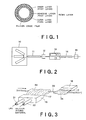
Fig. 1 is a cross-sectional view of a resin pipe in a first embodiment according to the present invention; -
Fig. 2 is a schematic plan view of a resin pipe manufacturing line for manufacturing the resin pipe shown inFig. 1 ; -
Fig. 3 is a schematic perspective view of assistance in explaining a silicon oxide film forming process; -
Fig. 4 is a graph comparatively showing the respective permeation-resisting abilities of a silicon dioxide film and a silicon monoxide film; -
Fig. 5 is a cross-sectional view of a resin pipe in a second embodiment according to the present invention; and -
Fig. 6 is a diagrammatic view of assistance in explaining a method of testing the permeation-resisting ability of resin pipes. - Resin pipes in preferred embodiments according to the present invention will be described with reference to the accompanying drawings.
- Referring to
Fig. 1 showing a resin pipe in a first embodiment according to the present invention in a cross-sectional view, the resin pipe has three resin layers. The three layers are a first layer, namely, an inner layer, a second layer, namely, an adhesive layer, and a third layer, namely, an outer layer. The outside surface of the third layer is coated with a silicon oxide film. The first and the third layer are made of any one of resins generally used for making fuel pipes of this type, such as polyamideresins including nylon 11,nylon 12 andnylon 6. - Referring to
Fig. 2 showing a resin pipe manufacturing line for manufacturing the resin pipe by a coextrusion process, the resin pipe manufacturing line is formed by arranging anextruder 10, acooling device 11, a take-up device 12, acoating device 13, acooling device 14 and a take-up device 15 in that order in a direction in which a resin pipe is carried. - The
extruder 10 extrudes molten resins respectively for forming the first, the second and the third layer to form the resin pipe. The resin pipe is passed through a water tank included in thecooling device 11 to cool and set the resin pipe. After the resins forming the first, the second and the third layer have been thus solidified, the take-updevice 12 takes up the resin pipe and delivers the resin pipe to thecoating device 13. The coating device d13 burns an organic silicon compound and an LPG in a space surrounding the resin pipe to coat the third layer with a silicon oxide film. -
Fig. 3 showscombustors 16 included in thecoating device 13. InFig. 3 , indicated at 30 is the resin pipe delivered from the take-updevice 12. Thecombustors 16 are disposed near a feed path along which theresin pipe 30 is moved obliquely opposite to each other respectively on the opposite sides of the feed path. The twocombustors 16 are disposed obliquely opposite to each other to coat theresin pipe 30 uniformly with a silicon oxide film. Thecoating device 13 may be provided with three or four combustors instead of the twocombustors 16. AnLPG supply pipe 31 for carrying an LPG and a silicon addingmaterial supply pipe 32 for carrying a silicon adding material containing an organic silicon compound, such as carbon silicate (SiC) are connected to eachcombustor 16. Eachcombustor 16 is provided with a flatflame projecting opening 17. Aflat flame 34 is projected through theflame projecting opening 17. Thecombustor 16 is provided with a combustion chamber. The LPG and the organic silicon compound are burned in the combustion chamber to cause reactions between the organic silicon compound and a hydrocarbon represented by chemical formula (1) or (2). Theflame 34 is projected through theflame projecting opening 17 toward theresin pipe 30 to coat theresin pipe 30 passing through theflame 34 with a silicon dioxide film or a silicon monoxide film.
SiC + C3H8 + 7O2 → SiO2 + 4H2O + 4CO2 (1)
2SiC + C3H8 + 7O2 → 2SiO + 4H2O + 4CO2 (2)
- The resin pipe of the present invention having the outside surface coated with the silicon dioxide film or the silicon monoxide film exercises the following effects when used for forming an automotive fuel line.
- A very small amount of fuel flowing through a resin pipe in an automotive fuel line permeates the resin pipe and is discharged outside. All kinds of resins are permeable to fuel in greater or lesser degrees. An ethylene-vinyl alcohol resin (EvOH) is an example of a functional resin used as a material for resin pipes. An EvOH is a functional resin having an excellent gas-barrier characteristic.
- Table 1 shows the results of the permeability test of a silicon film and an EvOH film. As obvious from Table 1, the permeability to ethanol and steam of the silicon film is lower than that of the EvOH film having a comparatively low permeability among resin films.
- The resin pipe in this embodiment is a composite multilayer structure having a resin body made of a resin inferior in permeation-resisting ability but inexpensive and excellent in workability, such as a polyamide resin and a silicon film coating the outside surface of the body. Fuel permeated the resin body is stopped by the silicon film. Thus the resin pipe of the present invention has an improved permeation-resisting ability far higher than that of the conventional resin pipe made of a low-permeability resin.
- There are two types of silicon films; a first silicon film containing silicon monoxide as a principal component and a second silicon film containing silicon dioxide as a principal component. Although both the first and the second silicon film are superior in permeation-resisting ability to resin films, the first and the second silicon film differ from each other in permeability to a gas (oxygen gas) as shown in
Fig. 4. Fig 4 comparatively shows the variation of the respective permeabilities to oxygen gas of a silicon monoxide film and a silicon dioxide film with temperature. It is obvious fromFig. 4 that both the respective permeabilities of the silicon monoxide film and the silicon dioxide film in crease as temperature rises and the permeability to gas of the silicon dioxide film is far lower than that of the silicon monoxide film. - Either the silicon monoxide film or the silicon dioxide film can be selectively formed over the outside surface of the resin tube in this embodiment by properly adjusting the flame temperature in the
combustors 16 of thecoating device 13. The outside surface of the resin pipe can be coated with a silicon dioxide film when the LPG is supplied at a comparatively high rate to thecombustors 16 and the flames in thecombustors 16 have a comparatively high frame temperature between 1300 and 1600°C. The outside surface of the resin pipe can be coated with a silicon monoxide film when the LPG is supplied at a comparatively low rate to thecombustors 16 and the flames in thecombustors 16 have a comparatively low frame temperature on the order of 800°C. - Either of a silicon monoxide film and the silicon dioxide film can be formed by properly adjusting the flame temperature in the combustors. Therefore, a resin pipe required to have a high permeation-resisting ability is coated with a silicon dioxide film, while a resin pipe required to have a moderate permeation-resisting ability is coated with a silicon monoxide film.
- Referring to
Fig. 5 showing a resin pipe in a second embodiment according to the present invention in a cross-sectional view, the resin pipe has three resin layers. The three layers are a first layer, namely, an inner layer to be exposed to fuel, a second layer, namely, an adhesive layer, and a third layer, namely, an outer layer. The outside surface of the third layer, similarly to that of the third layer of the resin pipe in the first embodiment, is coated with a silicon oxide film. The resin pipe in the second embodiment differs from the resin pipe in the first embodiment in that the silicon oxide film is coated with a fourth layer, namely, a protective layer. Preferably, the fourth layer as a protective layer is made of a thermoplastic elastomer or rubber, such as an EPDM. The fourth layer protects the silicon oxide film and increases the impact resistance of the resin pipe. Thus the silicon oxide film is protected from external damaging actions to maintain the low permeability of the resin pipe for a long period of use.Table 1 Permeability test of a silicon film and an EvOH film Silicon film EvOH film Ethanol 0.007g.mm/m2.24h 0.26.mm/m2.24h Steam 0.003g.mm/m2.24h 2.00.mm/m2.24h
Claims (8)
- A resin pipe of multilayer construction comprising a plurality of resin layers respectively made of thermoplastic resins,
wherein the surface of any one of the plurality of resin layers is coated with a silicon oxide film by a burning reaction of an organic silicon compound in flames according to one of chemical reactionsi)
SiC+C3H8+7O2→SiO2+4H2O+4CO2;
andii)wherein the flames are projected by two combustors disposed obliquely opposite to each other on the opposite sides of the feed path along which the resin pipe is fed to form the silicon oxide film thereon.
2SiC+C3H8+7O2→2SiO+4H2O+4CO2,
and - The resin pipe according to claim 1, wherein the resin layer having the surface coated with the silicon oxide film is the outermost one of the plurality of resin layers.
- The resin pipe according to claim 1, wherein the silicon oxide film is formed between the adjacent resin layers of the plurality of resin layers.
- The resin pipe according to claim 1 further comprising a protective layer coating the outside surface of the silicon oxide film to protect the silicon oxide film.
- The resin pipe according to claim 4, wherein the protective layer is made of rubber or a thermoplastic elastomer.
- The resin pipe according to Claim 1, wherein each combustor has a flat flame projecting opening through which flames are projected and the flat flame projecting opening is elongated in a direction in which the resin pipe is fed to form the silicon oxide film thereon.
- The resin pipe according to claim 6, wherein a liquefied petroleum gas supply pipe for carrying a liquefied petroleum gas and a silicon adding material supply pipe for carrying a silicon adding material containing an organic silicon compound are connected to the combustor, and the combustor is provided with a combustion chamber in which the liquid petroleum gas and the silicon adding material are burned.
- The resin pipe according to any one of claims 1 - 7, intended for use in an automotive fuel line.
Applications Claiming Priority (1)
| Application Number | Priority Date | Filing Date | Title |
|---|---|---|---|
| JP2004309698A JP2006118669A (en) | 2004-10-25 | 2004-10-25 | Resin tube |
Publications (2)
| Publication Number | Publication Date |
|---|---|
| EP1650017A1 EP1650017A1 (en) | 2006-04-26 |
| EP1650017B1 true EP1650017B1 (en) | 2014-01-22 |
Family
ID=35462410
Family Applications (1)
| Application Number | Title | Priority Date | Filing Date |
|---|---|---|---|
| EP05023007.7A Expired - Lifetime EP1650017B1 (en) | 2004-10-25 | 2005-10-21 | Resin pipe |
Country Status (4)
| Country | Link |
|---|---|
| US (1) | US20060086401A1 (en) |
| EP (1) | EP1650017B1 (en) |
| JP (1) | JP2006118669A (en) |
| CN (1) | CN100355559C (en) |
Families Citing this family (12)
| Publication number | Priority date | Publication date | Assignee | Title |
|---|---|---|---|---|
| JP2006118669A (en) * | 2004-10-25 | 2006-05-11 | Sanoh Industrial Co Ltd | Resin tube |
| CN100393456C (en) * | 2006-06-24 | 2008-06-11 | 中国科学技术大学 | Nano polycrystalline noble metal hollow sphere particle chain and preparation method thereof |
| US20100300574A1 (en) * | 2007-11-29 | 2010-12-02 | Yutaka Jinnouchi | Multiwall steel tube |
| WO2009095941A1 (en) * | 2008-01-30 | 2009-08-06 | Dayco Fluid Technologies S.P.A. | Multilayer hose for conveying an aqueous solution containing urea |
| JP5421664B2 (en) * | 2009-06-15 | 2014-02-19 | 有限会社コンタミネーション・コントロール・サービス | Coated molded article for storage or transfer of hydrocarbon compounds |
| KR100959242B1 (en) * | 2010-04-06 | 2010-05-20 | 전정자 | A resin tube with multiple inner conduits |
| CA2893843C (en) | 2012-12-21 | 2018-09-04 | Gilead Sciences, Inc. | Polycyclic-carbamoylpyridone compounds and their pharmaceutical use |
| WO2015047022A1 (en) * | 2013-09-30 | 2015-04-02 | 코오롱인더스트리 주식회사 | Film for vacuum thermal insulator |
| TWI677489B (en) | 2014-06-20 | 2019-11-21 | 美商基利科學股份有限公司 | Synthesis of polycyclic-carbamoylpyridone compounds |
| NO2717902T3 (en) | 2014-06-20 | 2018-06-23 | ||
| TW201613936A (en) | 2014-06-20 | 2016-04-16 | Gilead Sciences Inc | Crystalline forms of(2R,5S,13aR)-8-hydroxy-7,9-dioxo-n-(2,4,6-trifluorobenzyl)-2,3,4,5,7,9,13,13a-octahydro-2,5-methanopyrido[1',2':4,5]pyrazino[2,1-b][1,3]oxazepine-10-carboxamide |
| US20200347992A1 (en) * | 2019-05-02 | 2020-11-05 | Agility Fuel Systems Llc | Polymeric liner based gas cylinder with reduced permeability |
Citations (1)
| Publication number | Priority date | Publication date | Assignee | Title |
|---|---|---|---|---|
| EP1650017A1 (en) * | 2004-10-25 | 2006-04-26 | Sanoh Kogyo Kabushiki Kaisha | Resin pipe |
Family Cites Families (54)
| Publication number | Priority date | Publication date | Assignee | Title |
|---|---|---|---|---|
| US3442686A (en) * | 1964-03-13 | 1969-05-06 | Du Pont | Low permeability transparent packaging films |
| US4495907A (en) * | 1983-01-18 | 1985-01-29 | Cummins Engine Company, Inc. | Combustion chamber components for internal combustion engines |
| US4478874A (en) * | 1983-12-09 | 1984-10-23 | Cosden Technology, Inc. | Methods for improving the gas barrier properties of polymeric containers |
| DE3576802D1 (en) * | 1984-12-30 | 1990-05-03 | Ajinomoto Kk | TRANSPARENT PLASTIC MATERIAL BUSH. |
| US5100720A (en) * | 1987-10-07 | 1992-03-31 | Mitsubishi Monsanto Chemical Company Limited | Laminated film having gas barrier properties |
| US4934595A (en) * | 1988-08-19 | 1990-06-19 | Plastic Flamecoat Systems, Inc. | Method and aparatus for spray coating |
| JP2870784B2 (en) * | 1989-02-10 | 1999-03-17 | 株式会社ブリヂストン | Low permeability rubber hose |
| JP2890599B2 (en) * | 1990-02-06 | 1999-05-17 | ソニー株式会社 | Processing method |
| JPH0454842U (en) * | 1990-09-14 | 1992-05-11 | ||
| DE4122119A1 (en) * | 1991-07-04 | 1993-01-07 | Hoechst Ag | MULTILAYER OXYGEN BARRIER FILM, THESE PLASTIC PIPES AND USE THEREOF |
| JP2737527B2 (en) * | 1992-04-08 | 1998-04-08 | 豊田合成株式会社 | Multilayer rubber hose and method for producing the same |
| MX9303141A (en) * | 1992-05-28 | 1994-04-29 | Polar Materials Inc | METHODS AND DEVICES FOR DEPOSITING BARRIER COATINGS. |
| US5308649A (en) * | 1992-06-26 | 1994-05-03 | Polar Materials, Inc. | Methods for externally treating a container with application of internal bias gas |
| US5520334A (en) * | 1993-01-21 | 1996-05-28 | White; Randall R. | Air and fuel mixing chamber for a tuneable high velocity thermal spray gun |
| JP3335766B2 (en) * | 1994-06-22 | 2002-10-21 | ローム株式会社 | Resin molding method and resin molding apparatus for electronic components |
| WO1996028299A1 (en) * | 1995-03-14 | 1996-09-19 | Daicel Chemical Industries, Ltd. | Barrier composite film and process for the production thereof |
| JPH09133266A (en) * | 1995-11-09 | 1997-05-20 | Sekisui Chem Co Ltd | Fire resistant piping material |
| US5716683A (en) * | 1996-01-30 | 1998-02-10 | Becton, Dickinson And Company | Blood collection tube assembly |
| JPH1073226A (en) * | 1996-08-30 | 1998-03-17 | Hideo Kameyama | Manufacture of continuous catalyst body |
| US5900317A (en) * | 1996-09-13 | 1999-05-04 | Minnesota Mining & Manufacturing Company | Flame-treating process |
| US5985385A (en) * | 1997-05-23 | 1999-11-16 | No Fire Technologies, Inc. | Fire and heat protection wrap for conduits, cable trays, other electrical transmission lines and gas and oil pipelines |
| JP4268230B2 (en) * | 1997-07-04 | 2009-05-27 | 大日本印刷株式会社 | Laminate tube forming laminate and laminating tube container using the same |
| JPH11105151A (en) * | 1997-10-03 | 1999-04-20 | Tokai Rubber Ind Ltd | Hose with bellows protector and method of manufacturing the same |
| DE29822212U1 (en) * | 1998-01-17 | 1999-03-18 | Hewing GmbH, 48607 Ochtrup | Sanitary and / or heating installation items |
| DE19801861C2 (en) * | 1998-01-20 | 2001-10-18 | Schott Glas | Process for producing a hollow, internally coated molded glass body |
| US6214473B1 (en) * | 1998-05-13 | 2001-04-10 | Andrew Tye Hunt | Corrosion-resistant multilayer coatings |
| US6376093B1 (en) * | 1998-05-26 | 2002-04-23 | Toyo Boseki Kabushiki Kaisha | Polyamide film and polyamide laminate film |
| DE19850227C1 (en) * | 1998-10-26 | 2000-06-21 | Siegfried Schwert | Hose for lining pipes |
| US6433993B1 (en) * | 1998-11-23 | 2002-08-13 | Microcoating Technologies, Inc. | Formation of thin film capacitors |
| US6240970B1 (en) * | 1999-04-01 | 2001-06-05 | Itt Manufacturing Enterprises, Inc. | Tubing for handling hydrocarbon materials and having an outer jacket layer adhered thereto |
| SE520491C2 (en) * | 1999-04-07 | 2003-07-15 | Tetra Laval Holdings & Finance | Packaging laminate with barrier properties against gas and flavorings |
| FI118804B (en) * | 1999-12-03 | 2008-03-31 | Asm Int | Process for making oxide films |
| AU2001236043A1 (en) * | 2000-03-03 | 2001-09-12 | Toyoda Gosei Co. Ltd. | Resin hose for fuel |
| JP2001248972A (en) * | 2000-03-03 | 2001-09-14 | Nippon Steel Corp | Highly durable heat insulating material, its manufacturing method, its use and its construction method |
| US6368899B1 (en) * | 2000-03-08 | 2002-04-09 | Maxwell Electronic Components Group, Inc. | Electronic device packaging |
| JP2002079614A (en) * | 2000-06-19 | 2002-03-19 | Yokohama Rubber Co Ltd:The | Rubber/resin composite and low permeable hose using the same |
| FR2812666B1 (en) * | 2000-08-01 | 2003-08-08 | Sidel Sa | BARRIER COATING COMPRISING A PROTECTIVE LAYER, METHOD FOR OBTAINING SUCH A COATING AND CONTAINER PROVIDED WITH SUCH A COATING |
| JP2003080583A (en) * | 2000-08-31 | 2003-03-19 | Tokai Rubber Ind Ltd | Fuel hose manufacturing method and ultraviolet crosslinking composition used for the same |
| KR100387850B1 (en) * | 2000-12-29 | 2003-06-18 | 현대자동차주식회사 | Polyamide resin composition and synthetic resin product |
| FR2820805A1 (en) * | 2001-02-12 | 2002-08-16 | Cebal | A flexible thermoplastic tube for the packaging of cosmetic materials in which reduced oxygen permeability is obtained by the application of a coating of silicon oxide during flame treatment before application of the varnish |
| JP2002248702A (en) * | 2001-02-23 | 2002-09-03 | Tokai Rubber Ind Ltd | Low permeability membrane and low permeability hose |
| US6884482B2 (en) * | 2001-03-27 | 2005-04-26 | Kuraray Co., Ltd. | Fuel container having excellent gasoline barrier properties |
| US6467508B1 (en) * | 2001-10-12 | 2002-10-22 | Atofina Chemicals, Inc. | Low precipitate polyamide based tubing |
| US20030207103A1 (en) * | 2002-05-03 | 2003-11-06 | Zvosec Charles M. | System and method for protecting surfaces against corrosive compounds |
| JP3671966B2 (en) * | 2002-09-20 | 2005-07-13 | 日新電機株式会社 | Thin film forming apparatus and method |
| TWI322176B (en) * | 2002-10-17 | 2010-03-21 | Polymers Australia Pty Ltd | Fire resistant compositions |
| US7122234B2 (en) * | 2002-11-13 | 2006-10-17 | Tetra Laval Holding & Finance S.A. | Transparent plastic gas barrier packaging laminate |
| JP2004169851A (en) * | 2002-11-21 | 2004-06-17 | Sanoh Industrial Co Ltd | Multi-layer tube |
| EP1629901A4 (en) * | 2003-05-06 | 2006-06-07 | Yasuhiro Mori | Method for surface preparation of solid substances and surface-prepared solid substances |
| DE20307499U1 (en) * | 2003-05-13 | 2003-07-24 | Wegner, Werner, 78355 Hohenfels | Pipe-bending machine for automotive fuel lines, brakes, ventilation and cooling |
| US20050019580A1 (en) * | 2003-06-10 | 2005-01-27 | Mori Yasuhiro | Method for modifying surface of solid substrate, surface modified solid substrate and apparatus for modifying surface of solid substrate |
| ATE424288T1 (en) * | 2004-04-16 | 2009-03-15 | Advanced Plastics Technologies | PREFORM AND METHOD FOR PRODUCING THE PREFORM AND A BOTTLE |
| US7597938B2 (en) * | 2004-11-29 | 2009-10-06 | Guardian Industries Corp. | Method of making coated article with color suppression coating including flame pyrolysis deposited layer(s) |
| JP4479552B2 (en) * | 2005-03-22 | 2010-06-09 | 東海ゴム工業株式会社 | Hose and its manufacturing method |
-
2004
- 2004-10-25 JP JP2004309698A patent/JP2006118669A/en active Pending
-
2005
- 2005-10-11 US US11/247,546 patent/US20060086401A1/en not_active Abandoned
- 2005-10-21 EP EP05023007.7A patent/EP1650017B1/en not_active Expired - Lifetime
- 2005-10-25 CN CNB2005101180727A patent/CN100355559C/en not_active Expired - Lifetime
Patent Citations (1)
| Publication number | Priority date | Publication date | Assignee | Title |
|---|---|---|---|---|
| EP1650017A1 (en) * | 2004-10-25 | 2006-04-26 | Sanoh Kogyo Kabushiki Kaisha | Resin pipe |
Also Published As
| Publication number | Publication date |
|---|---|
| CN100355559C (en) | 2007-12-19 |
| JP2006118669A (en) | 2006-05-11 |
| US20060086401A1 (en) | 2006-04-27 |
| CN1765622A (en) | 2006-05-03 |
| EP1650017A1 (en) | 2006-04-26 |
Similar Documents
| Publication | Publication Date | Title |
|---|---|---|
| EP1650017A1 (en) | Resin pipe | |
| EP1741549B1 (en) | Multilayer hose for transporting high-temperature chemical and/or gas | |
| US6289915B1 (en) | Permeation and leak preventative design for fuel tank attachments | |
| US6555243B2 (en) | Thermoplastic multilayer composites | |
| US20050217747A1 (en) | Thermoplastic pipe and liners | |
| CN100537228C (en) | Multilayer structure | |
| US20040009315A1 (en) | Low permeation polymer fuel tank | |
| US20070104907A1 (en) | Multilayer structure and multilayer shaped article | |
| US8273432B2 (en) | Automotive fuel hose | |
| KR20090094771A (en) | Multilayer structure comprising one or more stabilized layers | |
| JP2004256096A (en) | Multi-layer fuel tank | |
| DE112022003981T5 (en) | MULTILAYER STRUCTURE WITH AN IMPROVED HYDROGEN BARRIER | |
| RU2319887C2 (en) | Flexible pipe made of material including thermoplastic polymer and polyolefin and used in oil or gas field development (variants) | |
| KR20010076420A (en) | Multilayer plastic pipe with good layer adhesion | |
| KR20150046790A (en) | Hydrogen transfer tube | |
| US7828334B2 (en) | Joint part for resin fuel tank | |
| US10065400B2 (en) | Fuel hose | |
| BR112012031367B1 (en) | hose and hose system | |
| US20060099367A1 (en) | Multilayer structure with excellent fuel barrier performance | |
| JP2004169851A (en) | Multi-layer tube | |
| CN106641493A (en) | Rubber pipe and preparation method and application thereof | |
| TW200732576A (en) | Steel pipe for automobile piping | |
| JP4249912B2 (en) | Multi-layer plastic container | |
| CN109268583A (en) | A kind of grain catcher system pressure difference sensor pipeline and preparation method thereof | |
| EP1285746A1 (en) | Emission reducing patch for multilayer plastic vessels |
Legal Events
| Date | Code | Title | Description |
|---|---|---|---|
| PUAI | Public reference made under article 153(3) epc to a published international application that has entered the european phase |
Free format text: ORIGINAL CODE: 0009012 |
|
| AK | Designated contracting states |
Kind code of ref document: A1 Designated state(s): AT BE BG CH CY CZ DE DK EE ES FI FR GB GR HU IE IS IT LI LT LU LV MC NL PL PT RO SE SI SK TR |
|
| AX | Request for extension of the european patent |
Extension state: AL BA HR MK YU |
|
| 17P | Request for examination filed |
Effective date: 20060705 |
|
| 17Q | First examination report despatched |
Effective date: 20060817 |
|
| AKX | Designation fees paid |
Designated state(s): DE GB |
|
| REG | Reference to a national code |
Ref country code: DE Ref legal event code: R079 Ref document number: 602005042551 Country of ref document: DE Free format text: PREVIOUS MAIN CLASS: B32B0001080000 Ipc: B32B0025080000 |
|
| RIC1 | Information provided on ipc code assigned before grant |
Ipc: B32B 1/08 20060101ALI20130717BHEP Ipc: B32B 25/08 20060101AFI20130717BHEP Ipc: F16L 11/04 20060101ALI20130717BHEP |
|
| GRAP | Despatch of communication of intention to grant a patent |
Free format text: ORIGINAL CODE: EPIDOSNIGR1 |
|
| INTG | Intention to grant announced |
Effective date: 20130906 |
|
| RAP1 | Party data changed (applicant data changed or rights of an application transferred) |
Owner name: SANOH KOGYO KABUSHIKI KAISHA |
|
| GRAS | Grant fee paid |
Free format text: ORIGINAL CODE: EPIDOSNIGR3 |
|
| GRAA | (expected) grant |
Free format text: ORIGINAL CODE: 0009210 |
|
| AK | Designated contracting states |
Kind code of ref document: B1 Designated state(s): DE GB |
|
| REG | Reference to a national code |
Ref country code: GB Ref legal event code: FG4D |
|
| REG | Reference to a national code |
Ref country code: DE Ref legal event code: R096 Ref document number: 602005042551 Country of ref document: DE Effective date: 20140306 |
|
| REG | Reference to a national code |
Ref country code: DE Ref legal event code: R097 Ref document number: 602005042551 Country of ref document: DE |
|
| PLBE | No opposition filed within time limit |
Free format text: ORIGINAL CODE: 0009261 |
|
| STAA | Information on the status of an ep patent application or granted ep patent |
Free format text: STATUS: NO OPPOSITION FILED WITHIN TIME LIMIT |
|
| 26N | No opposition filed |
Effective date: 20141023 |
|
| REG | Reference to a national code |
Ref country code: DE Ref legal event code: R097 Ref document number: 602005042551 Country of ref document: DE Effective date: 20141023 |
|
| GBPC | Gb: european patent ceased through non-payment of renewal fee |
Effective date: 20141021 |
|
| PG25 | Lapsed in a contracting state [announced via postgrant information from national office to epo] |
Ref country code: GB Free format text: LAPSE BECAUSE OF NON-PAYMENT OF DUE FEES Effective date: 20141021 |
|
| PGFP | Annual fee paid to national office [announced via postgrant information from national office to epo] |
Ref country code: DE Payment date: 20240828 Year of fee payment: 20 |
|
| REG | Reference to a national code |
Ref country code: DE Ref legal event code: R071 Ref document number: 602005042551 Country of ref document: DE |