EP1649831A1 - Injector - Google Patents
Injector Download PDFInfo
- Publication number
- EP1649831A1 EP1649831A1 EP04745341A EP04745341A EP1649831A1 EP 1649831 A1 EP1649831 A1 EP 1649831A1 EP 04745341 A EP04745341 A EP 04745341A EP 04745341 A EP04745341 A EP 04745341A EP 1649831 A1 EP1649831 A1 EP 1649831A1
- Authority
- EP
- European Patent Office
- Prior art keywords
- intraocular lens
- indicating means
- injector
- position indicating
- cartridge
- Prior art date
- Legal status (The legal status is an assumption and is not a legal conclusion. Google has not performed a legal analysis and makes no representation as to the accuracy of the status listed.)
- Granted
Links
Images


Classifications
-
- A—HUMAN NECESSITIES
- A61—MEDICAL OR VETERINARY SCIENCE; HYGIENE
- A61F—FILTERS IMPLANTABLE INTO BLOOD VESSELS; PROSTHESES; DEVICES PROVIDING PATENCY TO, OR PREVENTING COLLAPSING OF, TUBULAR STRUCTURES OF THE BODY, e.g. STENTS; ORTHOPAEDIC, NURSING OR CONTRACEPTIVE DEVICES; FOMENTATION; TREATMENT OR PROTECTION OF EYES OR EARS; BANDAGES, DRESSINGS OR ABSORBENT PADS; FIRST-AID KITS
- A61F2/00—Filters implantable into blood vessels; Prostheses, i.e. artificial substitutes or replacements for parts of the body; Appliances for connecting them with the body; Devices providing patency to, or preventing collapsing of, tubular structures of the body, e.g. stents
- A61F2/02—Prostheses implantable into the body
- A61F2/14—Eye parts, e.g. lenses, corneal implants; Implanting instruments specially adapted therefor; Artificial eyes
- A61F2/16—Intraocular lenses
- A61F2/1662—Instruments for inserting intraocular lenses into the eye
- A61F2/1678—Instruments for inserting intraocular lenses into the eye with a separate cartridge or other lens setting part for storage of a lens, e.g. preloadable for shipping
-
- A—HUMAN NECESSITIES
- A61—MEDICAL OR VETERINARY SCIENCE; HYGIENE
- A61F—FILTERS IMPLANTABLE INTO BLOOD VESSELS; PROSTHESES; DEVICES PROVIDING PATENCY TO, OR PREVENTING COLLAPSING OF, TUBULAR STRUCTURES OF THE BODY, e.g. STENTS; ORTHOPAEDIC, NURSING OR CONTRACEPTIVE DEVICES; FOMENTATION; TREATMENT OR PROTECTION OF EYES OR EARS; BANDAGES, DRESSINGS OR ABSORBENT PADS; FIRST-AID KITS
- A61F2/00—Filters implantable into blood vessels; Prostheses, i.e. artificial substitutes or replacements for parts of the body; Appliances for connecting them with the body; Devices providing patency to, or preventing collapsing of, tubular structures of the body, e.g. stents
- A61F2/02—Prostheses implantable into the body
- A61F2/14—Eye parts, e.g. lenses, corneal implants; Implanting instruments specially adapted therefor; Artificial eyes
- A61F2/16—Intraocular lenses
- A61F2/1662—Instruments for inserting intraocular lenses into the eye
- A61F2/167—Instruments for inserting intraocular lenses into the eye with pushable plungers
Definitions
- the present invention relates to an injector which is used at the time of inserting an intraocular lens into a capsula lentis.
- a soft material such as a silicon resin, an acrylate resin, or a hydrogel, is recently used as the material of the intraocular lens 7, and a surgery of inserting the intraocular lens from a small incision with that lens rolled or folded is performed.
- the method of the surgery there is a method of folding the intraocular lens 7 front side out by a forceps, inserting the lens in such a way that the loop 72 inserted in first becomes parallel to an eye of a patient, after which the intraocular lens 7 is released with the loop 72 kept in parallel, while being rotated clockwise as viewed from an operator in such a way that the back side of the intraocular lens 7 faces the vitreous-body side.
- an injector comprising a cartridge in which an intraocular lens 7 can be loaded with the front side thereof folded inwardly, a cylindrical injector main body with mount means on which the cartridge is detachably mounted, and ejection means which is fitted into the injector main body and can eject the intraocular lens 7, loaded in the cartridge, out of the cartridge (see, for example, Patent Literature 2).
- the loop 72 on the ejection side of the intraocular lens 7 loaded in the cartridge is tilted, if the intraocular lens 7 is inserted as it is, the loop 72 may harm a cornea or the like. To prevent this, the lens has only to be inserted in such a way that the loop 72 on the ejection side of the intraocular lens 72 loaded in the cartridge is in parallel to an eye of a patient. Since the loop 72 is very small, however, there is a problem such that it is difficult to figure out a location where the loop 72 becomes parallel.
- the intraocular lens 7 may be turned upside down if the intraocular lens 7 is released as it is, making it necessary to rotate the lens counterclockwise as viewed from an operator so that the front side of the intraocular lens 7 faces the surface of the eye.
- this rotation direction is opposite to the direction in the case where the forceps is used, however, there is a problem such that the operator is liable to mishandle the work.
- a cartridge in which the intraocular lens 7 can be loaded front side out may be used. Even in this case, however, there are problems such that the operator would wonder in which direction the injector should be rotated, and would have a difficulty in determining how much it should be rotated.
- the present invention has been made in view of the circumstances, and it is an object of the invention to provide an injector which enables an operator to safely insert an intraocular lens without a mishandling.
- an injector as set forth in claim 1 is an injector for inserting an intraocular lens which has a loop loaded in a cartridge into an eye by pushing out the lens while rotating the lens, characterized by comprising insertion-start-position indicating means for indicating a position at a time of starting inserting said intraocular lens, and insertion-complete-position indicating means for indicating a position at a time of completing the insertion of said intraocular lens.
- a cornea or the like can be prevented from being harmed by the loop of the intraocular lens.
- the injector as set forth in claim 2 is characterized in that the insertion-start-position indicating means is formed at a location which inclines with respect to the insertion-complete-position indicating means by an angle greater than 0° and less than 90°with a straight line, as a rotation axis, along which the intraocular lens moves when pushed out.
- a cornea or the like can be prevented from being harmed by the loop of the intraocular lens.
- the injector as set forth in claim 3 is characterized in that the insertion-start-position indicating means is formed at a location which inclines with respect to said insertion-complete-position indicating means by an angle greater than 0° and less than 45° with a straight line, as a rotation axis, along which said intraocular lens moves when inserted.
- a cornea or the like can be prevented from being harmed by the loop of the intraocular lens.
- the injector as set forth in claim 4 is characterized in that the insertion-start-position indicating means is formed at a location inclined at a clockwise angle with respect to the insertion-complete-position indicating means with a straight line, as a rotation axis, along which the intraocular lens moves when inserted in a case where the intraocular lens is inserted from a near side toward a far side.
- the injector which folds the intraocular lens front side out and rotates the lens in the same direction as that in the case of using a forceps, it is possible to easily figure out an angle at which the ejection-side loop of the intraocular lens loaded in the cartridge becomes in parallel to the surface of the eye. It is also possible to easily figure out the direction of rotating the cartridge when the intraocular lens is ejected into the eye, thus preventing the inserted intraocular lens from turning upside down.
- the injector according to claim 5 is characterized by comprising rotation-direction indicating means for indicating a direction in which the cartridge is rotated when the intraocular lens is inserted in the eye.
- a first embodiment of the invention is an injector provided with insertion-start-position indicating means.
- an injector 1 comprises an injector main body 4 having insertion-complete-position indicating means 2 on which a cartridge 6 is detachably mounted, and which indicates a position as a measure of completing insertion of an intraocular lens and insertion-start-position indicating means 3 which indicates a position as a measure of starting the insertion of the intraocular lens 7, and ejection means 5 which can eject the intraocular lens 7, loaded in the cartridge 6, out of the cartridge 6.
- Various materials can be used for the injector 1 unless they cause a trouble in the insertion of the intraocular lens 7 into an eye; for example, metals, such as stainless steel and titanium, can be used.
- the ejection means 5 comprises a base 51 which is fitted into the injector main body 4, a pushrod 52 which is formed on one end side of the base 51, and pushes out the intraocular lens 7 loaded in the cartridge 6, and a latch portion 53 which is so formed on the other end side of the base 51 as to be larger than the diameter of the injector main body 4.
- a hoe-like shaped push-out portion 54 Formed on the leading end of the pushrod 52 is a hoe-like shaped push-out portion 54 which, in abutment on the side face of the folded intraocular lens 7, can push the lens out.
- the injector main body 4 is formed like a cylinder so as to have a fitting channel inside into which the base 51 of the ejection means 5 can be fitted from one end side.
- Support means 41 by which the fingers or the like of an operator are fixed at the time of the insertion of the intraocular lens 7 is fixed on the exterior surface of the injector main body 4 by fixing means like a screw.
- the other end side of the injector main body 4 is provided with the insertion-complete-position indicating means 2 on which the cartridge 6 is detachably mounted, and which indicates the measure of completing the insertion of the intraocular lens.
- the insertion-complete-position indicating means 2 is formed with a guide section 22 hemi-arcuate in cross section which has two guide channels 21 for guiding a wing portion 66 of the cartridge and protrudes from the injector main body 4, and the two guide channels 21 indicate the measure of completing the insertion of the intraocular lens 7.
- Formed on the leading-end side of the guide section 22 are a front-side latch piece 23 which protrudes upward and can latch the front side of the wing portion 66, and a top-side latch piece 24 which protrudes toward the injector main body 4 from the upper part of the front-side latch piece 23, and can latch the top side of the wing portion 66.
- the insertion-complete-position indicating means 2 is not limited to that as long as the cartridge 6 can be mounted thereon, and may take other structures.
- the insertion-start-position indicating means 3 is constituted by a flat-surface portion 31 which is notched in the side of the injector main body 4, and indicates the position where a loop 72 on the ejection side at the time of starting the insertion of the intraocular lens 7 becomes horizontal in a case where the orientation of the insertion-start-position indicating means 3 is set horizontal.
- the flat-surface portion 31 may be formed at a location inclined by an angle greater than 0° and less than 90° with respect to the insertion-complete-position indicating means 2 with a straight line, as the rotation axis, along which the intraocular lens 7 moves when pushed out, and it is preferable that the flat-surface portion should be formed at a location by an angle greater than 0° and less than 45°. Accordingly, arranging the flat-surface portion 31 in parallel with an eye can make the loop 72 on the ejection side parallel to the surface of the eye at the time of starting the insertion.
- the insertion-start-position indicating means 3 is not limited to one formed in a planar shape by notching the curved surface of the injector main body 4, and, for example, other methods like coloring may be applicable.
- the cartridge 6 which is mounted on the injector 1 comprises, as illustrated in, for example, FIG. 4, a cartridge main body 65 which has an introduction tube 61, an inlet portion 62, an outlet portion 63, and insertion grooves 64, and the wing portion 66 which is so formed as to protrude from both sides of the cartridge main body 65 and be attachable to and detachable from the insertion-complete-position indicating means 2.
- the inlet portion 62 is for loading the folded intraocular lens 7, and its upper and bottom parts are provided with the insertion grooves 64.
- the insertion grooves 64 are for loading the intraocular lens 7 held by a forceps, and the insertion of the forceps into the insertion grooves 64 facilitates the insertion of the folded intraocular lens 7 into the inlet portion 62.
- the interior of the introduction tube 61 is formed like a tubular shape through which the folded and loaded intraocular lens 7 can pass from the inlet portion 62 toward the outlet portion 63.
- the outlet portion 63 is formed angled to the longitudinal axis, i.e., the cut surface is oblique.
- the leading end part of the outlet portion is so formed as to incline with respect to the longitudinal axis at the same angle as that of the insertion-start-position indicating means 3 when the cartridge is mounted on the injector. This can facilitate insertion of the outlet portion 63 into the incision of the eye.
- the intraocular lens 7 is folded and picked up by a forceps or the like in such a way that the front of that lens faces outward, and is inserted into the inlet portion 62 of the cartridge 6 in such a way that the loop 72 on the ejection side comes above the other loop 73.
- the bottom face of the wing portion 66 of the cartridge 6 is made to abut on the guide paths 21 of the insertion-complete-position indicating means 2, slid toward the front-side latch piece 23 in that state, and the wing portion 66 is sandwiched and supported between the top-side latch piece 24 and the guide channels 21.
- the push-out portion 54 of the ejection means 5 is made to abut on the side of an optical part 71 of the intraocular lens 7 to push out the lens until the leading end of the loop 72 on the ejection side reaches the outlet portion 63. This will finish preparation of the injector 1.
- the ejection nozzle 63 of the cartridge 6 is inserted into an incision 8 of the eyeball, and the loop 72 on the ejection side is pushed out into the eye. Accordingly, the loop 72 can be inserted while being kept in parallel to the eye (see FIG. 5(a)).
- an operator gradually pushes out the intraocular lens 7 into the eye though the ejection means 5 while keeping the loop 72 on the ejection side in parallel to the surface of the eye (see FIG. 4(b) or (d)), and releases the optical part (see FIG. 4(e)). That is, the injector 1 is rotated clockwise to the direction of insertion, at which time the insertion-complete-position indicating means 2 becomes the measure of the insertion-complete position, and it is preferable that the injector should be rotated beyond the insertion-complete position to safely insert the intraocular lens 7 without turning around that lens in the eye. Because the operator has only to rotate the injector 1 in a direction in which the insertion-complete-position indicating means 2 becomes horizontal, it is possible to safely insert the intraocular lens 7 without making the rotation in the wrong direction.
- the injector 1 is so operated as to set the rear loop 73 in a capsula, and the outlet portion 63 is pulled off from the incision, thereby finishing the operation.
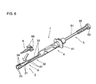
- a second embodiment of the invention is an injector provided with rotation-direction indicating means.
- insertion-start-position indicating means 32 is formed in a hemi-arcuate shape in cross section by cutting the injector main body 4 in half at an arbitrary width, and is formed in such a way that the loop 72 on the ejection side becomes parallel to the surface of an eye when two insertion-position indication portions 33 are arranged in parallel to the surface of the eye.
- Rotation-direction indicating means 9 is so formed in a hemi-arcuate shape in cross section as to have a rotation-direction indication channels 91 which connect the insertion-position indication portions 33 of the insertion-start-position indicating means 32 to the guide channels 21 of the insertion-complete-position indicating means 2, and is so formed as to turn the insertion-complete-position indicating means 2 counterclockwise from the insertion-start-position indicating means 32 with respect to the direction of inserting the intraocular lens 7 into the eye.
- the insertion-complete-position indicating means 2 may be formed at a location counterclockwise from the insertion-start-position indicating means 32 by an angle greater than 0° and less than 90°, and preferably formed at a location counterclockwise from the insertion-start-position indicating means 32 by an angle greater than 0° and less than 45°.
- rotation-direction indicating means 9 is structured in this manner, an operator has only to rotate the injector 1 along the rotation-direction indication channels 91 after ejecting the loop 72 on the ejection side in the eye, and can therefore easily figure out the direction of rotating the injector 1, and surely fit the inserted intraocular lens 7 without turning it upside down.
- a quadruple thread portion 55 is provided between the base 51 and the latch portion 53, and an engagement portion (not illustrated) which can engage with a groove 56 of the quadruple thread portion is provided on the interior surface of the injector main body 4. Accordingly, the ejection means can be pushed forward while being rotated with the groove 56 of the quadruple thread 55 engaged with the engagement portion, and fitting the base 51, pushrod 52, and the push-out portion 54 of the ejection means 5 can be slacked, and the intraocular lens 7 can be ejected safely.
- the injector 1 uses the cartridge 6 in which the intraocular lens 7 folded front side out is loaded
- the embodiments are not restrictive, and needless to say, the invention is also applicable to a case where the injector 1 uses the cartridge 6 in which the intraocular lens 7 folded front side in is loaded.
- the insertion-complete-position indicating means 2 may be formed at a location rotated clockwise from the insertion-start-position indicating means 3 by an angle greater than 0° and less than 90° if the orientation of the intraocular lens 7 is toward the far side from the near side with the straight line, as a rotation axis, along which the intraocular lens 7 moves at the time of the insertion, and the insertion-complete-position indicating means 2 should preferably be formed at a location inclined clockwise from the insertion-start-position indicating means 3 by an angle greater than 0° and less than 45°.
Abstract
Description
- The present invention relates to an injector which is used at the time of inserting an intraocular lens into a capsula lentis.
- There is a method of implanting an
intraocular lens 7 which has, as illustrated in FIG. 7, anoptical part 71, and twoloops optical part 71 and supporting theoptical part 71 from an incision formed in an eyeball instead of a crystalline lens which has lost its function due to cataract, thereby recovering a vision (see, for example, Patent Literature 1). - From the standpoint of hastening the recovery of a patient, it is desired that the incision is as small as possible. Because of this demand, a soft material, such as a silicon resin, an acrylate resin, or a hydrogel, is recently used as the material of the
intraocular lens 7, and a surgery of inserting the intraocular lens from a small incision with that lens rolled or folded is performed. - As the method of the surgery, there is a method of folding the
intraocular lens 7 front side out by a forceps, inserting the lens in such a way that theloop 72 inserted in first becomes parallel to an eye of a patient, after which theintraocular lens 7 is released with theloop 72 kept in parallel, while being rotated clockwise as viewed from an operator in such a way that the back side of theintraocular lens 7 faces the vitreous-body side. - According to the method, however, handling the forceps is difficult, and there are risks such as dropping the
intraocular lens 7 and enlarging the incision, which brings about a problem such that the surgery largely depends on the skill of the operator. - Recently, as means of solving such a problem, there is an injector comprising a cartridge in which an
intraocular lens 7 can be loaded with the front side thereof folded inwardly, a cylindrical injector main body with mount means on which the cartridge is detachably mounted, and ejection means which is fitted into the injector main body and can eject theintraocular lens 7, loaded in the cartridge, out of the cartridge (see, for example, Patent Literature 2). - Patent Literature 1: Japanese Unexamined Patent Publication No. H7-255757 (p. 2, FIG. 3)
- Patent Literature 2: Japanese Unexamined Patent Publication No. 2003-70830 (p. 3, FIG. 1)
- With the injector in use, because the
loop 72 on the ejection side of theintraocular lens 7 loaded in the cartridge is tilted, if theintraocular lens 7 is inserted as it is, theloop 72 may harm a cornea or the like. To prevent this, the lens has only to be inserted in such a way that theloop 72 on the ejection side of theintraocular lens 72 loaded in the cartridge is in parallel to an eye of a patient. Since theloop 72 is very small, however, there is a problem such that it is difficult to figure out a location where theloop 72 becomes parallel. - In a case where the lens is inserted in such a way that the
loop 72 becomes parallel to the surface of the eye, theintraocular lens 7 may be turned upside down if theintraocular lens 7 is released as it is, making it necessary to rotate the lens counterclockwise as viewed from an operator so that the front side of theintraocular lens 7 faces the surface of the eye. As this rotation direction is opposite to the direction in the case where the forceps is used, however, there is a problem such that the operator is liable to mishandle the work. To resolve this, a cartridge in which theintraocular lens 7 can be loaded front side out may be used. Even in this case, however, there are problems such that the operator would wonder in which direction the injector should be rotated, and would have a difficulty in determining how much it should be rotated. - The present invention has been made in view of the circumstances, and it is an object of the invention to provide an injector which enables an operator to safely insert an intraocular lens without a mishandling.
- To achieve the object, an injector as set forth in
claim 1 is an injector for inserting an intraocular lens which has a loop loaded in a cartridge into an eye by pushing out the lens while rotating the lens, characterized by comprising insertion-start-position indicating means for indicating a position at a time of starting inserting said intraocular lens, and insertion-complete-position indicating means for indicating a position at a time of completing the insertion of said intraocular lens. - Accordingly, as it is possible to easily figure out the orientation of the intraocular lens loaded in the cartridge at the time the intraocular lens is inserted, a cornea or the like can be prevented from being harmed by the loop of the intraocular lens.
- The injector as set forth in
claim 2 is characterized in that the insertion-start-position indicating means is formed at a location which inclines with respect to the insertion-complete-position indicating means by an angle greater than 0° and less than 90°with a straight line, as a rotation axis, along which the intraocular lens moves when pushed out. - Accordingly, as it is possible to easily figure out the orientation of the intraocular lens loaded in the cartridge at the time the intraocular lens is inserted, a cornea or the like can be prevented from being harmed by the loop of the intraocular lens.
- The injector as set forth in
claim 3 is characterized in that the insertion-start-position indicating means is formed at a location which inclines with respect to said insertion-complete-position indicating means by an angle greater than 0° and less than 45° with a straight line, as a rotation axis, along which said intraocular lens moves when inserted. - Accordingly, as it is possible to easily figure out the orientation of the intraocular lens loaded in the cartridge at the time the intraocular lens is inserted, a cornea or the like can be prevented from being harmed by the loop of the intraocular lens.
- The injector as set forth in
claim 4 is characterized in that the insertion-start-position indicating means is formed at a location inclined at a clockwise angle with respect to the insertion-complete-position indicating means with a straight line, as a rotation axis, along which the intraocular lens moves when inserted in a case where the intraocular lens is inserted from a near side toward a far side. - Accordingly, also in the injector which folds the intraocular lens front side out and rotates the lens in the same direction as that in the case of using a forceps, it is possible to easily figure out an angle at which the ejection-side loop of the intraocular lens loaded in the cartridge becomes in parallel to the surface of the eye. It is also possible to easily figure out the direction of rotating the cartridge when the intraocular lens is ejected into the eye, thus preventing the inserted intraocular lens from turning upside down.
- The injector according to
claim 5 is characterized by comprising rotation-direction indicating means for indicating a direction in which the cartridge is rotated when the intraocular lens is inserted in the eye. - This makes it possible to easily figure out the direction of the rotation and the amount of the rotation, so that the inserted intraocular lens does not turn upside down.
-
- [FIG. 1] A perspective view illustrating an injector according to a first embodiment of the invention.
- [FIG. 2] A front view illustrating ejection means of the invention.
- [FIG. 3] A schematic perspective view illustrating mount means of the invention.
- [FIG. 4] A perspective view illustrating a cartridge.
- [FIG. 5] An explanatory diagram illustrating how to use the injector of the invention.
- [FIG. 6] A perspective diagram illustrating an injector according to a second embodiment of the invention.
- [FIG. 7] A front view of an intraocular lens as viewed from the front side.
- Best Mode for Carrying Out the Invention
- Embodiments of the invention will now be explained with reference to the accompanying drawings.
- A first embodiment of the invention is an injector provided with insertion-start-position indicating means.
- As illustrated in FIG. 1, an
injector 1 comprises an injectormain body 4 having insertion-complete-position indicating means 2 on which acartridge 6 is detachably mounted, and which indicates a position as a measure of completing insertion of an intraocular lens and insertion-start-position indicating means 3 which indicates a position as a measure of starting the insertion of theintraocular lens 7, and ejection means 5 which can eject theintraocular lens 7, loaded in thecartridge 6, out of thecartridge 6. Various materials can be used for theinjector 1 unless they cause a trouble in the insertion of theintraocular lens 7 into an eye; for example, metals, such as stainless steel and titanium, can be used. - As illustrated in FIG. 2, the ejection means 5 comprises a
base 51 which is fitted into the injectormain body 4, apushrod 52 which is formed on one end side of thebase 51, and pushes out theintraocular lens 7 loaded in thecartridge 6, and alatch portion 53 which is so formed on the other end side of thebase 51 as to be larger than the diameter of the injectormain body 4. Formed on the leading end of thepushrod 52 is a hoe-like shaped push-outportion 54 which, in abutment on the side face of the foldedintraocular lens 7, can push the lens out. - The injector
main body 4 is formed like a cylinder so as to have a fitting channel inside into which thebase 51 of the ejection means 5 can be fitted from one end side. Support means 41 by which the fingers or the like of an operator are fixed at the time of the insertion of theintraocular lens 7 is fixed on the exterior surface of the injectormain body 4 by fixing means like a screw. The other end side of the injectormain body 4 is provided with the insertion-complete-position indicating means 2 on which thecartridge 6 is detachably mounted, and which indicates the measure of completing the insertion of the intraocular lens. - As illustrated in FIG. 3, the insertion-complete-
position indicating means 2 is formed with aguide section 22 hemi-arcuate in cross section which has twoguide channels 21 for guiding awing portion 66 of the cartridge and protrudes from the injectormain body 4, and the twoguide channels 21 indicate the measure of completing the insertion of theintraocular lens 7. Formed on the leading-end side of theguide section 22 are a front-side latch piece 23 which protrudes upward and can latch the front side of thewing portion 66, and a top-side latch piece 24 which protrudes toward the injectormain body 4 from the upper part of the front-side latch piece 23, and can latch the top side of thewing portion 66. The insertion-complete-position indicating means 2 is not limited to that as long as thecartridge 6 can be mounted thereon, and may take other structures. - As illustrated in FIG. 1, the insertion-start-
position indicating means 3 is constituted by a flat-surface portion 31 which is notched in the side of the injectormain body 4, and indicates the position where aloop 72 on the ejection side at the time of starting the insertion of theintraocular lens 7 becomes horizontal in a case where the orientation of the insertion-start-position indicating means 3 is set horizontal. For example, in a case where thecartridge 6 in which theintraocular lens 7 is loaded while being folded front side out is used, the flat-surface portion 31 may be formed at a location inclined by an angle greater than 0° and less than 90° with respect to the insertion-complete-position indicating means 2 with a straight line, as the rotation axis, along which theintraocular lens 7 moves when pushed out, and it is preferable that the flat-surface portion should be formed at a location by an angle greater than 0° and less than 45°. Accordingly, arranging the flat-surface portion 31 in parallel with an eye can make theloop 72 on the ejection side parallel to the surface of the eye at the time of starting the insertion. - The insertion-start-
position indicating means 3 is not limited to one formed in a planar shape by notching the curved surface of the injectormain body 4, and, for example, other methods like coloring may be applicable. - The
cartridge 6 which is mounted on theinjector 1 comprises, as illustrated in, for example, FIG. 4, a cartridgemain body 65 which has anintroduction tube 61, aninlet portion 62, anoutlet portion 63, andinsertion grooves 64, and thewing portion 66 which is so formed as to protrude from both sides of the cartridgemain body 65 and be attachable to and detachable from the insertion-complete-position indicating means 2. - The
inlet portion 62 is for loading the foldedintraocular lens 7, and its upper and bottom parts are provided with theinsertion grooves 64. Theinsertion grooves 64 are for loading theintraocular lens 7 held by a forceps, and the insertion of the forceps into theinsertion grooves 64 facilitates the insertion of the foldedintraocular lens 7 into theinlet portion 62. The interior of theintroduction tube 61 is formed like a tubular shape through which the folded and loadedintraocular lens 7 can pass from theinlet portion 62 toward theoutlet portion 63. - Given that the lengthwise direction of the
introduction tube 61 is a longitudinal axis, theoutlet portion 63 is formed angled to the longitudinal axis, i.e., the cut surface is oblique. The leading end part of the outlet portion is so formed as to incline with respect to the longitudinal axis at the same angle as that of the insertion-start-position indicating means 3 when the cartridge is mounted on the injector. This can facilitate insertion of theoutlet portion 63 into the incision of the eye. - Next, how to use the
injector 1 will be explained with reference to FIG. 5. - First, the
intraocular lens 7 is folded and picked up by a forceps or the like in such a way that the front of that lens faces outward, and is inserted into theinlet portion 62 of thecartridge 6 in such a way that theloop 72 on the ejection side comes above theother loop 73. Next, the bottom face of thewing portion 66 of thecartridge 6 is made to abut on theguide paths 21 of the insertion-complete-position indicating means 2, slid toward the front-side latch piece 23 in that state, and thewing portion 66 is sandwiched and supported between the top-side latch piece 24 and theguide channels 21. Subsequently, the push-outportion 54 of the ejection means 5 is made to abut on the side of anoptical part 71 of theintraocular lens 7 to push out the lens until the leading end of theloop 72 on the ejection side reaches theoutlet portion 63. This will finish preparation of theinjector 1. - Next, with the flat-
surface portion 31 of the insertion-start-position indicating means 2 so supported as to be parallel to the surface of the eye, theejection nozzle 63 of thecartridge 6 is inserted into anincision 8 of the eyeball, and theloop 72 on the ejection side is pushed out into the eye. Accordingly, theloop 72 can be inserted while being kept in parallel to the eye (see FIG. 5(a)). - After that, an operator gradually pushes out the
intraocular lens 7 into the eye though the ejection means 5 while keeping theloop 72 on the ejection side in parallel to the surface of the eye (see FIG. 4(b) or (d)), and releases the optical part (see FIG. 4(e)). That is, theinjector 1 is rotated clockwise to the direction of insertion, at which time the insertion-complete-position indicating means 2 becomes the measure of the insertion-complete position, and it is preferable that the injector should be rotated beyond the insertion-complete position to safely insert theintraocular lens 7 without turning around that lens in the eye. Because the operator has only to rotate theinjector 1 in a direction in which the insertion-complete-position indicating means 2 becomes horizontal, it is possible to safely insert theintraocular lens 7 without making the rotation in the wrong direction. - Finally, the
injector 1 is so operated as to set therear loop 73 in a capsula, and theoutlet portion 63 is pulled off from the incision, thereby finishing the operation. - A second embodiment of the invention is an injector provided with rotation-direction indicating means.
- As illustrated in FIG. 6, insertion-start-position indicating means 32 is formed in a hemi-arcuate shape in cross section by cutting the injector
main body 4 in half at an arbitrary width, and is formed in such a way that theloop 72 on the ejection side becomes parallel to the surface of an eye when two insertion-position indication portions 33 are arranged in parallel to the surface of the eye. - Rotation-direction indicating means 9 is so formed in a hemi-arcuate shape in cross section as to have a rotation-
direction indication channels 91 which connect the insertion-position indication portions 33 of the insertion-start-position indicating means 32 to theguide channels 21 of the insertion-complete-position indicating means 2, and is so formed as to turn the insertion-complete-position indicating means 2 counterclockwise from the insertion-start-position indicating means 32 with respect to the direction of inserting theintraocular lens 7 into the eye. In this case, if the orientation of inserting theintraocular lens 7 is toward the far side from the near side with respect to the direction of inserting theintraocular lens 7 into the eye, the insertion-complete-position indicating means 2 may be formed at a location counterclockwise from the insertion-start-position indicating means 32 by an angle greater than 0° and less than 90°, and preferably formed at a location counterclockwise from the insertion-start-position indicating means 32 by an angle greater than 0° and less than 45°. As the rotation-direction indicating means 9 is structured in this manner, an operator has only to rotate theinjector 1 along the rotation-direction indication channels 91 after ejecting theloop 72 on the ejection side in the eye, and can therefore easily figure out the direction of rotating theinjector 1, and surely fit the insertedintraocular lens 7 without turning it upside down. - In the ejection means 5, a
quadruple thread portion 55 is provided between the base 51 and thelatch portion 53, and an engagement portion (not illustrated) which can engage with a groove 56 of the quadruple thread portion is provided on the interior surface of the injectormain body 4. Accordingly, the ejection means can be pushed forward while being rotated with the groove 56 of thequadruple thread 55 engaged with the engagement portion, and fitting the base 51,pushrod 52, and the push-outportion 54 of the ejection means 5 can be slacked, and theintraocular lens 7 can be ejected safely. - In FIG. 5, the same portions as those of the first embodiment are denoted by the same reference numerals to omit their explanations.
- In the embodiments, although explanations have been given of the case where the
injector 1 uses thecartridge 6 in which theintraocular lens 7 folded front side out is loaded, the embodiments are not restrictive, and needless to say, the invention is also applicable to a case where theinjector 1 uses thecartridge 6 in which theintraocular lens 7 folded front side in is loaded. In this case, for example, the insertion-complete-position indicating means 2 may be formed at a location rotated clockwise from the insertion-start-position indicating means 3 by an angle greater than 0° and less than 90° if the orientation of theintraocular lens 7 is toward the far side from the near side with the straight line, as a rotation axis, along which theintraocular lens 7 moves at the time of the insertion, and the insertion-complete-position indicating means 2 should preferably be formed at a location inclined clockwise from the insertion-start-position indicating means 3 by an angle greater than 0° and less than 45°.
Claims (5)
- An injector for inserting an intraocular lens which has a loop loaded in a cartridge into an eye by pushing out said lens while rotating said lens, comprising insertion-start-position indicating means for indicating a position at a time of starting inserting said intraocular lens, and insertion-complete-position indicating means for indicating a position at a time of completing the insertion of said intraocular lens.
- The injector according to claim 1, wherein said insertion-start-position indicating means is formed at a location which inclines with respect to said insertion-complete-position indicating means by an angle greater than 0° and less than 90°with a straight line, as a rotation axis, along which said intraocular lens moves when pushed out.
- The injector according to claim 1, wherein said insertion-start-position indicating means is formed at a location which inclines with respect to said insertion-complete-position indicating means by an angle greater than 0° and less than 45° with a straight line, as a rotation axis, along which said intraocular lens moves when inserted.
- The injector according to claim 1, wherein said insertion-start-position indicating means is formed at a location inclined at a clockwise angle with respect to said insertion-complete-position indicating means with a straight line, as a rotation axis, along which said intraocular lens moves when inserted in a case where said intraocular lens is inserted from a near side toward a far side.
- The injector according to claim 1, comprising rotation-direction indicating means for indicating a direction in which said cartridge is rotated when said intraocular lens is inserted in the eye.
Applications Claiming Priority (2)
| Application Number | Priority Date | Filing Date | Title |
|---|---|---|---|
| JP2003149215 | 2003-05-27 | ||
| PCT/JP2004/007189 WO2004105648A1 (en) | 2003-05-27 | 2004-05-26 | Injector |
Publications (3)
| Publication Number | Publication Date |
|---|---|
| EP1649831A1 true EP1649831A1 (en) | 2006-04-26 |
| EP1649831A4 EP1649831A4 (en) | 2006-10-18 |
| EP1649831B1 EP1649831B1 (en) | 2009-04-22 |
Family
ID=33487145
Family Applications (1)
| Application Number | Title | Priority Date | Filing Date |
|---|---|---|---|
| EP04745341A Active EP1649831B1 (en) | 2003-05-27 | 2004-05-26 | Injector for intraocular lens |
Country Status (7)
| Country | Link |
|---|---|
| US (1) | US20060293694A1 (en) |
| EP (1) | EP1649831B1 (en) |
| JP (1) | JPWO2004105648A1 (en) |
| AT (1) | ATE429193T1 (en) |
| DE (1) | DE602004020775D1 (en) |
| ES (1) | ES2322957T3 (en) |
| WO (1) | WO2004105648A1 (en) |
Cited By (3)
| Publication number | Priority date | Publication date | Assignee | Title |
|---|---|---|---|---|
| CN102283741A (en) * | 2011-07-14 | 2011-12-21 | 广州卫视博生物科技有限公司 | Folding artificial vitreous body injector |
| US8926628B2 (en) | 2005-04-15 | 2015-01-06 | Abbott Medical Optics Inc. | Multi-action device for inserting an intraocular lens into an eye |
| EP2301478A4 (en) * | 2008-06-17 | 2017-06-21 | Hoya Corporation | Intraocular lens insertion instrument |
Families Citing this family (39)
| Publication number | Priority date | Publication date | Assignee | Title |
|---|---|---|---|---|
| FR2833154B1 (en) | 2001-12-12 | 2004-11-19 | Ioltechnologie Production | CASSETTE AND FLEXIBLE INTRAOCULAR LENS INJECTOR AND METHOD FOR INJECTING SUCH LENSES |
| WO2006070628A1 (en) | 2004-12-27 | 2006-07-06 | Hoya Corporation | Intraocular lens implanting device |
| US8545512B2 (en) | 2005-01-26 | 2013-10-01 | Hoya Corporation | Intraocular lens insertion device |
| JP4836046B2 (en) | 2005-02-24 | 2011-12-14 | Hoya株式会社 | Intraocular lens insertion device |
| US7892283B2 (en) * | 2005-04-08 | 2011-02-22 | Abbott Medical Optics Inc. | Methods and apparatus for inserting an intraocular lens into an eye |
| US7892282B2 (en) | 2005-04-08 | 2011-02-22 | Abbott Medical Optics Inc. | Methods and apparatus for inserting an intraocular lens into an eye |
| JP4922174B2 (en) | 2005-09-28 | 2012-04-25 | Hoya株式会社 | Intraocular lens insertion device |
| JP4877643B2 (en) | 2005-12-08 | 2012-02-15 | Hoya株式会社 | Intraocular lens insertion device |
| US8377125B2 (en) * | 2006-04-05 | 2013-02-19 | Anew Optics, Inc. | Intraocular lens with accommodation |
| US8460375B2 (en) * | 2006-08-14 | 2013-06-11 | Novartis Ag | Lens delivery system |
| US7879090B2 (en) | 2006-12-13 | 2011-02-01 | Bausch & Lomb Incorporated | Intraocular lens injector apparatus and methods of use |
| JP5236638B2 (en) | 2007-05-30 | 2013-07-17 | Hoya株式会社 | Intraocular lens insertion device |
| JP5236637B2 (en) | 2007-05-30 | 2013-07-17 | Hoya株式会社 | Intraocular lens insertion device and intraocular lens insertion device |
| JP5086713B2 (en) | 2007-07-11 | 2012-11-28 | Hoya株式会社 | Intraocular lens insertion device |
| US8480734B2 (en) | 2007-12-27 | 2013-07-09 | Anew Optics, Inc. | Intraocular lens with accommodation |
| US8702794B2 (en) * | 2008-04-28 | 2014-04-22 | Abbott Medical Optics Inc. | Back loaded IOL insertion cartridge |
| JP5254669B2 (en) | 2008-06-05 | 2013-08-07 | Hoya株式会社 | Intraocular lens insertion device and cartridge |
| US8273122B2 (en) | 2008-06-23 | 2012-09-25 | Abbott Medical Optics Inc. | Pre-loaded IOL insertion system |
| JP5323420B2 (en) | 2008-08-21 | 2013-10-23 | Hoya株式会社 | Intraocular lens insertion device |
| JP5416379B2 (en) | 2008-09-04 | 2014-02-12 | Hoya株式会社 | Intraocular lens insertion device |
| EP2361060A4 (en) * | 2008-11-26 | 2014-02-26 | Anew Optics Inc | Haptic devices for intraocular lens |
| US10010405B2 (en) | 2008-11-26 | 2018-07-03 | Anew Aol Technologies, Inc. | Haptic devices for intraocular lens |
| WO2010079780A1 (en) | 2009-01-07 | 2010-07-15 | Hoya株式会社 | Intraocular lens insertion device |
| WO2010102121A1 (en) * | 2009-03-04 | 2010-09-10 | Anew Optics, Inc. | Injector for intraocular lens |
| EP2555708B1 (en) | 2010-04-08 | 2015-03-18 | Hoya Corporation | Ocular implant insertion apparatus |
| JP5511530B2 (en) | 2010-06-10 | 2014-06-04 | Hoya株式会社 | Intraocular lens insertion device |
| AU2011293388B2 (en) | 2010-08-24 | 2017-01-05 | Johnson & Johnson Surgical Vision, Inc. | Advanced pushrod and pushrod assembly features |
| DK2854708T3 (en) | 2012-06-04 | 2017-01-30 | Alcon Pharmaceuticals Ltd | DEVICE FOR INSTALLING AN INTRAOCULAR LENS AND PROCEDURE FOR EXTING AN INTRAOCULAR LENS FROM A PATTERN |
| EP2858593B1 (en) | 2012-06-12 | 2020-09-30 | Alcon Inc. | Intraocular gas injector |
| CA153455S (en) * | 2013-04-22 | 2015-01-06 | Santen Pharmaceutical Co Ltd | Operation-guiding cylinder for intraocular lens implantation device |
| WO2014181250A1 (en) | 2013-05-09 | 2014-11-13 | Sasol Technology (Proprietary) Limited | Tetramerisation of ethylene |
| US10010408B2 (en) | 2014-04-04 | 2018-07-03 | Alcon Pharmaceuticals, Ltd. | Intraocular lens inserter |
| JP6646987B2 (en) | 2015-09-16 | 2020-02-14 | Hoya株式会社 | Intraocular lens insertion device |
| WO2017047714A1 (en) | 2015-09-16 | 2017-03-23 | Hoya株式会社 | Intraocular lens insertion tool |
| US10172706B2 (en) | 2015-10-31 | 2019-01-08 | Novartis Ag | Intraocular lens inserter |
| JP6929843B2 (en) | 2016-06-28 | 2021-09-01 | Hoya株式会社 | Intraocular lens inserter |
| US11000367B2 (en) | 2017-01-13 | 2021-05-11 | Alcon Inc. | Intraocular lens injector |
| CN109700573A (en) * | 2017-10-25 | 2019-05-03 | 爱博诺德(北京)医疗科技有限公司 | There is the importing head of crystal Pseudophakia |
| US11224537B2 (en) | 2018-10-19 | 2022-01-18 | Alcon Inc. | Intraocular gas injector |
Citations (2)
| Publication number | Priority date | Publication date | Assignee | Title |
|---|---|---|---|---|
| US6162229A (en) * | 1992-09-30 | 2000-12-19 | Staar Surgical Company, Inc. | Deformable intraocular lens injecting apparatus with deformable tip plunger |
| US20020133167A1 (en) * | 1996-07-10 | 2002-09-19 | Allergan | IOL insertion apparatus and method for marking and using same |
Family Cites Families (11)
| Publication number | Priority date | Publication date | Assignee | Title |
|---|---|---|---|---|
| US4104339A (en) * | 1975-12-03 | 1978-08-01 | Fetz James G | Method for the manufacture of intraocular lenses |
| US4304012A (en) * | 1979-10-05 | 1981-12-08 | Iolab Corporation | Intraocular lens assembly with improved mounting to the iris |
| US4370760A (en) * | 1981-03-25 | 1983-02-01 | Kelman Charles D | Anterior chamber intraocular lens |
| US4573998A (en) * | 1982-02-05 | 1986-03-04 | Staar Surgical Co. | Methods for implantation of deformable intraocular lenses |
| US4836201A (en) * | 1988-03-24 | 1989-06-06 | Patton Medical Technologies, Inc. | "Envelope" apparatus for inserting intra-ocular lens into the eye |
| US5807400A (en) * | 1992-09-30 | 1998-09-15 | Staar Surgical Company, Inc. | Deformable intraocular lens insertion system |
| JP3412104B2 (en) * | 1993-08-04 | 2003-06-03 | キヤノンスター株式会社 | Deformable intraocular lens insertion device |
| JP2571193B2 (en) * | 1994-06-02 | 1997-01-16 | 新平 矢田 | Puncture device for drain tube insertion |
| US6251114B1 (en) * | 1999-10-29 | 2001-06-26 | Allergan Sales, Inc. | Rotatable IOL insertion apparatus and method for using same |
| GB0011507D0 (en) * | 2000-05-13 | 2000-06-28 | Duckworth & Kent Ltd | Ophthalmic lens injectors |
| JP4269300B2 (en) * | 2000-08-30 | 2009-05-27 | マニー株式会社 | Ophthalmic knife |
-
2004
- 2004-04-30 US US10/558,344 patent/US20060293694A1/en not_active Abandoned
- 2004-05-26 JP JP2005506483A patent/JPWO2004105648A1/en active Pending
- 2004-05-26 DE DE602004020775T patent/DE602004020775D1/en active Active
- 2004-05-26 AT AT04745341T patent/ATE429193T1/en not_active IP Right Cessation
- 2004-05-26 WO PCT/JP2004/007189 patent/WO2004105648A1/en active Application Filing
- 2004-05-26 ES ES04745341T patent/ES2322957T3/en active Active
- 2004-05-26 EP EP04745341A patent/EP1649831B1/en active Active
Patent Citations (2)
| Publication number | Priority date | Publication date | Assignee | Title |
|---|---|---|---|---|
| US6162229A (en) * | 1992-09-30 | 2000-12-19 | Staar Surgical Company, Inc. | Deformable intraocular lens injecting apparatus with deformable tip plunger |
| US20020133167A1 (en) * | 1996-07-10 | 2002-09-19 | Allergan | IOL insertion apparatus and method for marking and using same |
Non-Patent Citations (1)
| Title |
|---|
| See also references of WO2004105648A1 * |
Cited By (3)
| Publication number | Priority date | Publication date | Assignee | Title |
|---|---|---|---|---|
| US8926628B2 (en) | 2005-04-15 | 2015-01-06 | Abbott Medical Optics Inc. | Multi-action device for inserting an intraocular lens into an eye |
| EP2301478A4 (en) * | 2008-06-17 | 2017-06-21 | Hoya Corporation | Intraocular lens insertion instrument |
| CN102283741A (en) * | 2011-07-14 | 2011-12-21 | 广州卫视博生物科技有限公司 | Folding artificial vitreous body injector |
Also Published As
| Publication number | Publication date |
|---|---|
| EP1649831A4 (en) | 2006-10-18 |
| DE602004020775D1 (en) | 2009-06-04 |
| JPWO2004105648A1 (en) | 2006-07-20 |
| WO2004105648A1 (en) | 2004-12-09 |
| ATE429193T1 (en) | 2009-05-15 |
| ES2322957T3 (en) | 2009-07-02 |
| US20060293694A1 (en) | 2006-12-28 |
| EP1649831B1 (en) | 2009-04-22 |
Similar Documents
| Publication | Publication Date | Title |
|---|---|---|
| EP1649831B1 (en) | Injector for intraocular lens | |
| US9980811B2 (en) | Ocular implant insertion apparatus and methods | |
| US8470030B2 (en) | Device for loading an intraocular lens into an injection cartridge | |
| TWI626932B (en) | Injector for intraocular lens | |
| EP2301478B1 (en) | Intraocular lens insertion device | |
| US5571113A (en) | Surgical probe with tips for plastic lens implantation in the eye | |
| EP2298242B1 (en) | Assembly for use with a intraocular lens | |
| EP1262154B1 (en) | Intraocular lens injection instrument | |
| US5395378A (en) | Eye implantable lens haptics insertion and twist apparatus | |
| US6540754B2 (en) | Apparatus and method for multiply folding and inserting an intraocular lens in an eye | |
| TWI608852B (en) | Injector for intraocular lens | |
| US20040059343A1 (en) | Novel enhanced system for intraocular lens insertion | |
| JP7429814B2 (en) | Injector with handle entraining front and rear displacement mechanism | |
| US11911263B2 (en) | Packaging-assisted actuation for an intraocular lens cartridge | |
| EP3222247A1 (en) | Intraocular lens insertion tool |
Legal Events
| Date | Code | Title | Description |
|---|---|---|---|
| PUAI | Public reference made under article 153(3) epc to a published international application that has entered the european phase |
Free format text: ORIGINAL CODE: 0009012 |
|
| 17P | Request for examination filed |
Effective date: 20051117 |
|
| AK | Designated contracting states |
Kind code of ref document: A1 Designated state(s): AT BE BG CH CY CZ DE DK EE ES FI FR GB GR HU IE IT LI LU MC NL PL PT RO SE SI SK TR |
|
| RIN1 | Information on inventor provided before grant (corrected) |
Inventor name: FUTAMURA,HIDEYUKIHOYA CORPORATION |
|
| DAX | Request for extension of the european patent (deleted) | ||
| A4 | Supplementary search report drawn up and despatched |
Effective date: 20060915 |
|
| 17Q | First examination report despatched |
Effective date: 20071026 |
|
| GRAP | Despatch of communication of intention to grant a patent |
Free format text: ORIGINAL CODE: EPIDOSNIGR1 |
|
| RTI1 | Title (correction) |
Free format text: INJECTOR FOR INTRAOCULAR LENS |
|
| GRAP | Despatch of communication of intention to grant a patent |
Free format text: ORIGINAL CODE: EPIDOSNIGR1 |
|
| GRAS | Grant fee paid |
Free format text: ORIGINAL CODE: EPIDOSNIGR3 |
|
| GRAA | (expected) grant |
Free format text: ORIGINAL CODE: 0009210 |
|
| AK | Designated contracting states |
Kind code of ref document: B1 Designated state(s): AT BE BG CH CY CZ DE DK EE ES FI FR GB GR HU IE IT LI LU MC NL PL PT RO SE SI SK TR |
|
| REG | Reference to a national code |
Ref country code: GB Ref legal event code: FG4D |
|
| REG | Reference to a national code |
Ref country code: CH Ref legal event code: EP |
|
| REG | Reference to a national code |
Ref country code: IE Ref legal event code: FG4D |
|
| REF | Corresponds to: |
Ref document number: 602004020775 Country of ref document: DE Date of ref document: 20090604 Kind code of ref document: P |
|
| REG | Reference to a national code |
Ref country code: ES Ref legal event code: FG2A Ref document number: 2322957 Country of ref document: ES Kind code of ref document: T3 |
|
| NLV1 | Nl: lapsed or annulled due to failure to fulfill the requirements of art. 29p and 29m of the patents act | ||
| PG25 | Lapsed in a contracting state [announced via postgrant information from national office to epo] |
Ref country code: AT Free format text: LAPSE BECAUSE OF FAILURE TO SUBMIT A TRANSLATION OF THE DESCRIPTION OR TO PAY THE FEE WITHIN THE PRESCRIBED TIME-LIMIT Effective date: 20090422 Ref country code: FI Free format text: LAPSE BECAUSE OF FAILURE TO SUBMIT A TRANSLATION OF THE DESCRIPTION OR TO PAY THE FEE WITHIN THE PRESCRIBED TIME-LIMIT Effective date: 20090422 Ref country code: PT Free format text: LAPSE BECAUSE OF FAILURE TO SUBMIT A TRANSLATION OF THE DESCRIPTION OR TO PAY THE FEE WITHIN THE PRESCRIBED TIME-LIMIT Effective date: 20090822 |
|
| PG25 | Lapsed in a contracting state [announced via postgrant information from national office to epo] |
Ref country code: SE Free format text: LAPSE BECAUSE OF FAILURE TO SUBMIT A TRANSLATION OF THE DESCRIPTION OR TO PAY THE FEE WITHIN THE PRESCRIBED TIME-LIMIT Effective date: 20090722 Ref country code: NL Free format text: LAPSE BECAUSE OF FAILURE TO SUBMIT A TRANSLATION OF THE DESCRIPTION OR TO PAY THE FEE WITHIN THE PRESCRIBED TIME-LIMIT Effective date: 20090422 Ref country code: SI Free format text: LAPSE BECAUSE OF FAILURE TO SUBMIT A TRANSLATION OF THE DESCRIPTION OR TO PAY THE FEE WITHIN THE PRESCRIBED TIME-LIMIT Effective date: 20090422 Ref country code: PL Free format text: LAPSE BECAUSE OF FAILURE TO SUBMIT A TRANSLATION OF THE DESCRIPTION OR TO PAY THE FEE WITHIN THE PRESCRIBED TIME-LIMIT Effective date: 20090422 |
|
| PG25 | Lapsed in a contracting state [announced via postgrant information from national office to epo] |
Ref country code: MC Free format text: LAPSE BECAUSE OF NON-PAYMENT OF DUE FEES Effective date: 20090531 |
|
| REG | Reference to a national code |
Ref country code: CH Ref legal event code: PL |
|
| PG25 | Lapsed in a contracting state [announced via postgrant information from national office to epo] |
Ref country code: DK Free format text: LAPSE BECAUSE OF FAILURE TO SUBMIT A TRANSLATION OF THE DESCRIPTION OR TO PAY THE FEE WITHIN THE PRESCRIBED TIME-LIMIT Effective date: 20090422 Ref country code: LI Free format text: LAPSE BECAUSE OF NON-PAYMENT OF DUE FEES Effective date: 20090531 Ref country code: RO Free format text: LAPSE BECAUSE OF FAILURE TO SUBMIT A TRANSLATION OF THE DESCRIPTION OR TO PAY THE FEE WITHIN THE PRESCRIBED TIME-LIMIT Effective date: 20090422 Ref country code: EE Free format text: LAPSE BECAUSE OF FAILURE TO SUBMIT A TRANSLATION OF THE DESCRIPTION OR TO PAY THE FEE WITHIN THE PRESCRIBED TIME-LIMIT Effective date: 20090422 Ref country code: CZ Free format text: LAPSE BECAUSE OF FAILURE TO SUBMIT A TRANSLATION OF THE DESCRIPTION OR TO PAY THE FEE WITHIN THE PRESCRIBED TIME-LIMIT Effective date: 20090422 Ref country code: CH Free format text: LAPSE BECAUSE OF NON-PAYMENT OF DUE FEES Effective date: 20090531 |
|
| PG25 | Lapsed in a contracting state [announced via postgrant information from national office to epo] |
Ref country code: SK Free format text: LAPSE BECAUSE OF FAILURE TO SUBMIT A TRANSLATION OF THE DESCRIPTION OR TO PAY THE FEE WITHIN THE PRESCRIBED TIME-LIMIT Effective date: 20090422 Ref country code: BE Free format text: LAPSE BECAUSE OF FAILURE TO SUBMIT A TRANSLATION OF THE DESCRIPTION OR TO PAY THE FEE WITHIN THE PRESCRIBED TIME-LIMIT Effective date: 20090422 |
|
| PLBE | No opposition filed within time limit |
Free format text: ORIGINAL CODE: 0009261 |
|
| STAA | Information on the status of an ep patent application or granted ep patent |
Free format text: STATUS: NO OPPOSITION FILED WITHIN TIME LIMIT |
|
| 26N | No opposition filed |
Effective date: 20100125 |
|
| PG25 | Lapsed in a contracting state [announced via postgrant information from national office to epo] |
Ref country code: BG Free format text: LAPSE BECAUSE OF FAILURE TO SUBMIT A TRANSLATION OF THE DESCRIPTION OR TO PAY THE FEE WITHIN THE PRESCRIBED TIME-LIMIT Effective date: 20090722 |
|
| PG25 | Lapsed in a contracting state [announced via postgrant information from national office to epo] |
Ref country code: IE Free format text: LAPSE BECAUSE OF NON-PAYMENT OF DUE FEES Effective date: 20090526 |
|
| PG25 | Lapsed in a contracting state [announced via postgrant information from national office to epo] |
Ref country code: GR Free format text: LAPSE BECAUSE OF FAILURE TO SUBMIT A TRANSLATION OF THE DESCRIPTION OR TO PAY THE FEE WITHIN THE PRESCRIBED TIME-LIMIT Effective date: 20090723 |
|
| PG25 | Lapsed in a contracting state [announced via postgrant information from national office to epo] |
Ref country code: LU Free format text: LAPSE BECAUSE OF NON-PAYMENT OF DUE FEES Effective date: 20090526 |
|
| PG25 | Lapsed in a contracting state [announced via postgrant information from national office to epo] |
Ref country code: HU Free format text: LAPSE BECAUSE OF FAILURE TO SUBMIT A TRANSLATION OF THE DESCRIPTION OR TO PAY THE FEE WITHIN THE PRESCRIBED TIME-LIMIT Effective date: 20091023 |
|
| PG25 | Lapsed in a contracting state [announced via postgrant information from national office to epo] |
Ref country code: TR Free format text: LAPSE BECAUSE OF FAILURE TO SUBMIT A TRANSLATION OF THE DESCRIPTION OR TO PAY THE FEE WITHIN THE PRESCRIBED TIME-LIMIT Effective date: 20090422 |
|
| PG25 | Lapsed in a contracting state [announced via postgrant information from national office to epo] |
Ref country code: CY Free format text: LAPSE BECAUSE OF FAILURE TO SUBMIT A TRANSLATION OF THE DESCRIPTION OR TO PAY THE FEE WITHIN THE PRESCRIBED TIME-LIMIT Effective date: 20090422 |
|
| PGFP | Annual fee paid to national office [announced via postgrant information from national office to epo] |
Ref country code: IT Payment date: 20140522 Year of fee payment: 11 Ref country code: ES Payment date: 20140411 Year of fee payment: 11 |
|
| PG25 | Lapsed in a contracting state [announced via postgrant information from national office to epo] |
Ref country code: IT Free format text: LAPSE BECAUSE OF NON-PAYMENT OF DUE FEES Effective date: 20150526 |
|
| REG | Reference to a national code |
Ref country code: FR Ref legal event code: PLFP Year of fee payment: 13 |
|
| REG | Reference to a national code |
Ref country code: ES Ref legal event code: FD2A Effective date: 20160627 |
|
| PG25 | Lapsed in a contracting state [announced via postgrant information from national office to epo] |
Ref country code: ES Free format text: LAPSE BECAUSE OF NON-PAYMENT OF DUE FEES Effective date: 20150527 |
|
| REG | Reference to a national code |
Ref country code: FR Ref legal event code: PLFP Year of fee payment: 14 |
|
| REG | Reference to a national code |
Ref country code: FR Ref legal event code: PLFP Year of fee payment: 15 |
|
| REG | Reference to a national code |
Ref country code: FR Ref legal event code: PLFP Year of fee payment: 20 |
|
| P01 | Opt-out of the competence of the unified patent court (upc) registered |
Effective date: 20230418 |
|
| PGFP | Annual fee paid to national office [announced via postgrant information from national office to epo] |
Ref country code: FR Payment date: 20230411 Year of fee payment: 20 Ref country code: DE Payment date: 20230331 Year of fee payment: 20 |
|
| PGFP | Annual fee paid to national office [announced via postgrant information from national office to epo] |
Ref country code: GB Payment date: 20230406 Year of fee payment: 20 |