EP1649331B1 - System and method for the identification of automation components - Google Patents
System and method for the identification of automation components Download PDFInfo
- Publication number
- EP1649331B1 EP1649331B1 EP04740866A EP04740866A EP1649331B1 EP 1649331 B1 EP1649331 B1 EP 1649331B1 EP 04740866 A EP04740866 A EP 04740866A EP 04740866 A EP04740866 A EP 04740866A EP 1649331 B1 EP1649331 B1 EP 1649331B1
- Authority
- EP
- European Patent Office
- Prior art keywords
- identification
- unit
- automation
- identification unit
- component
- Prior art date
- Legal status (The legal status is an assumption and is not a legal conclusion. Google has not performed a legal analysis and makes no representation as to the accuracy of the status listed.)
- Active
Links
- 238000000034 method Methods 0.000 title claims description 33
- 230000002093 peripheral effect Effects 0.000 claims description 51
- 230000003213 activating effect Effects 0.000 claims description 10
- 230000004913 activation Effects 0.000 claims description 6
- 230000008569 process Effects 0.000 claims description 4
- 238000002347 injection Methods 0.000 claims 2
- 239000007924 injection Substances 0.000 claims 2
- 230000010354 integration Effects 0.000 claims 1
- 238000000926 separation method Methods 0.000 claims 1
- 238000004519 manufacturing process Methods 0.000 description 11
- 230000008878 coupling Effects 0.000 description 7
- 238000010168 coupling process Methods 0.000 description 7
- 238000005859 coupling reaction Methods 0.000 description 7
- 230000005540 biological transmission Effects 0.000 description 4
- 230000001939 inductive effect Effects 0.000 description 4
- 238000004891 communication Methods 0.000 description 3
- 101100407151 Arabidopsis thaliana PBL6 gene Proteins 0.000 description 2
- 230000000712 assembly Effects 0.000 description 2
- 238000000429 assembly Methods 0.000 description 2
- 238000010586 diagram Methods 0.000 description 2
- 238000005516 engineering process Methods 0.000 description 2
- 238000009434 installation Methods 0.000 description 2
- 230000003993 interaction Effects 0.000 description 2
- 238000012423 maintenance Methods 0.000 description 2
- 238000012544 monitoring process Methods 0.000 description 2
- 239000010749 BS 2869 Class C1 Substances 0.000 description 1
- 230000006978 adaptation Effects 0.000 description 1
- 238000013500 data storage Methods 0.000 description 1
- 230000006735 deficit Effects 0.000 description 1
- 238000005259 measurement Methods 0.000 description 1
- 230000004044 response Effects 0.000 description 1
Images


Classifications
-
- G—PHYSICS
- G05—CONTROLLING; REGULATING
- G05B—CONTROL OR REGULATING SYSTEMS IN GENERAL; FUNCTIONAL ELEMENTS OF SUCH SYSTEMS; MONITORING OR TESTING ARRANGEMENTS FOR SUCH SYSTEMS OR ELEMENTS
- G05B19/00—Programme-control systems
- G05B19/02—Programme-control systems electric
- G05B19/04—Programme control other than numerical control, i.e. in sequence controllers or logic controllers
- G05B19/12—Programme control other than numerical control, i.e. in sequence controllers or logic controllers using record carriers
-
- G—PHYSICS
- G05—CONTROLLING; REGULATING
- G05B—CONTROL OR REGULATING SYSTEMS IN GENERAL; FUNCTIONAL ELEMENTS OF SUCH SYSTEMS; MONITORING OR TESTING ARRANGEMENTS FOR SUCH SYSTEMS OR ELEMENTS
- G05B19/00—Programme-control systems
- G05B19/02—Programme-control systems electric
- G05B19/418—Total factory control, i.e. centrally controlling a plurality of machines, e.g. direct or distributed numerical control [DNC], flexible manufacturing systems [FMS], integrated manufacturing systems [IMS], computer integrated manufacturing [CIM]
- G05B19/4183—Total factory control, i.e. centrally controlling a plurality of machines, e.g. direct or distributed numerical control [DNC], flexible manufacturing systems [FMS], integrated manufacturing systems [IMS], computer integrated manufacturing [CIM] characterised by data acquisition, e.g. workpiece identification
-
- G—PHYSICS
- G05—CONTROLLING; REGULATING
- G05B—CONTROL OR REGULATING SYSTEMS IN GENERAL; FUNCTIONAL ELEMENTS OF SUCH SYSTEMS; MONITORING OR TESTING ARRANGEMENTS FOR SUCH SYSTEMS OR ELEMENTS
- G05B2219/00—Program-control systems
- G05B2219/20—Pc systems
- G05B2219/25—Pc structure of the system
- G05B2219/25297—Identify controlled element, valve, and read characteristics
-
- G—PHYSICS
- G05—CONTROLLING; REGULATING
- G05B—CONTROL OR REGULATING SYSTEMS IN GENERAL; FUNCTIONAL ELEMENTS OF SUCH SYSTEMS; MONITORING OR TESTING ARRANGEMENTS FOR SUCH SYSTEMS OR ELEMENTS
- G05B2219/00—Program-control systems
- G05B2219/30—Nc systems
- G05B2219/31—From computer integrated manufacturing till monitoring
- G05B2219/31034—Component identifier and location indicator corresponding to component
-
- G—PHYSICS
- G05—CONTROLLING; REGULATING
- G05B—CONTROL OR REGULATING SYSTEMS IN GENERAL; FUNCTIONAL ELEMENTS OF SUCH SYSTEMS; MONITORING OR TESTING ARRANGEMENTS FOR SUCH SYSTEMS OR ELEMENTS
- G05B2219/00—Program-control systems
- G05B2219/30—Nc systems
- G05B2219/31—From computer integrated manufacturing till monitoring
- G05B2219/31283—Communication memory, storage, ram, eprom on workpiece or pallet
-
- G—PHYSICS
- G05—CONTROLLING; REGULATING
- G05B—CONTROL OR REGULATING SYSTEMS IN GENERAL; FUNCTIONAL ELEMENTS OF SUCH SYSTEMS; MONITORING OR TESTING ARRANGEMENTS FOR SUCH SYSTEMS OR ELEMENTS
- G05B2219/00—Program-control systems
- G05B2219/30—Nc systems
- G05B2219/33—Director till display
- G05B2219/33203—Wireless transmission of power and data, inductively, rotary transformer
-
- Y—GENERAL TAGGING OF NEW TECHNOLOGICAL DEVELOPMENTS; GENERAL TAGGING OF CROSS-SECTIONAL TECHNOLOGIES SPANNING OVER SEVERAL SECTIONS OF THE IPC; TECHNICAL SUBJECTS COVERED BY FORMER USPC CROSS-REFERENCE ART COLLECTIONS [XRACs] AND DIGESTS
- Y02—TECHNOLOGIES OR APPLICATIONS FOR MITIGATION OR ADAPTATION AGAINST CLIMATE CHANGE
- Y02P—CLIMATE CHANGE MITIGATION TECHNOLOGIES IN THE PRODUCTION OR PROCESSING OF GOODS
- Y02P90/00—Enabling technologies with a potential contribution to greenhouse gas [GHG] emissions mitigation
- Y02P90/02—Total factory control, e.g. smart factories, flexible manufacturing systems [FMS] or integrated manufacturing systems [IMS]
Landscapes
- Engineering & Computer Science (AREA)
- Physics & Mathematics (AREA)
- General Physics & Mathematics (AREA)
- Automation & Control Theory (AREA)
- General Engineering & Computer Science (AREA)
- Manufacturing & Machinery (AREA)
- Quality & Reliability (AREA)
- Automatic Assembly (AREA)
- Tests Of Electronic Circuits (AREA)
- General Factory Administration (AREA)
- Arrangements For Transmission Of Measured Signals (AREA)
Description
Die Erfindung betrifft ein System zur Identifizierung von Automatisierungskomponenten, insbesondere von Sensoren, Aktoren und Leitungskomponenten eines Automatisierungssystems. Die Erfindung betrifft weiter ein Verfahren zur Identifizierung von Automatisierungskomponenten, eine Identifikationseinheit sowie eine Leseeinheit für ein System zur Identifizierung von Automatisierungskomponenten.The invention relates to a system for the identification of automation components, in particular of sensors, actuators and line components of an automation system. The invention further relates to a method for identifying automation components, an identification unit and a reading unit for a system for identifying automation components.
Die Erfindung kommt insbesondere auf dem Gebiet der Automatisierungstechnik zum Einsatz. Automatisierte Produktions- und Fertigungsanlagen bestehen prinzipiell aus den zu automatisierenden Anlagenteilen (Produktions- und Fertigungseinrichtungen), aus dem Automatisierungssystem und aus Koppelelementen zwischen Anlage und Automatisierungssystem (Sensoren, Aktoren und den für deren Anschaltung notwendige Leitungskomponenten. Für die Erfassung und Beeinflussung von Prozessgrößen (Temperatur, Druck, Ventilstellung, etc.) werden häufig passive nichtintelligente Sensoren sowie nichtintelligente Aktoren verwendet. Hierzu gehören Sensoren (Thermoelemente, Thermowiderstände, Drucksensoren, Widerstandgeber, Stellungssensoren, etc.), Aktoren (Ventile, Relais, Motoren, etc.) und Leitungskomponenten (Thermoleitungen, Ausgleichsleitungen, Kompensationsdosen, etc.).The invention is used in particular in the field of automation technology. Automated production and manufacturing systems basically consist of the parts of the plant to be automated (production and production facilities), the automation system and coupling elements between the plant and the automation system (sensors, actuators and the line components necessary for their connection.) For the acquisition and influencing of process variables (temperature , Passive, non-intelligent sensors are often used, such as sensors (thermocouples, thermoresistors, pressure sensors, resistance sensors, position sensors, etc.), actuators (valves, relays, motors, etc.), and line components ( Thermoelectric cables, compensating cables, compensation boxes, etc.).
Aus der WO 03/017015 A1 ist ein Verfahren zur Kennzeichnung von Baugruppen oder Baueinheiten, welche aus wenigstens zwei Einzelkomponenten bestehen, bekannt. Bei der Herstellung und Montage der Einzelkomponenten werden charakteristische Daten der Einzelkomponenten wie z.B. deren Herkunft, charakterisierende Eigenschaftswerte oder die Fertigung der Einzelkomponenten charakterisierende Daten in einem beliebigen Datenspeicher abgelegt. Bei der Montage der Einzelkomponenten zur Baugruppe oder Baueinheit werden die Baugruppe oder Baueinheit charakterisierende Daten wie beispielsweise deren Eigenschaftskennwerte, Betriebs- und/oder Funktionsdaten der Baugruppe oder Baueinheit usw. erfasst. Die die Einzelkomponenten charakterisierende Daten werden aus dem Datenspeicher ausgelesen und mit den die Baugruppe oder die Baueinheit charakterisierenden Daten in eine auslesbare programmierbare Datenspeichereinheit übernommen, welche an der Baugruppe oder der Baueinheit angeordnet ist.From WO 03/017015 A1 a method for the identification of assemblies or assemblies, which consist of at least two individual components, known. In the production and assembly of the individual components, characteristic data of the individual components, such as their origin, characterizing property values or data characterizing the production of the individual components, are stored in any data memory. When assembling the individual components for Assembly or assembly, the module or unit characterizing data such as their property characteristics, operating and / or functional data of the module or assembly, etc. are detected. The data characterizing the individual components are read from the data memory and taken over with the data characterizing the module or the unit data in a readable programmable data storage unit, which is arranged on the module or the unit.
Diese Aufgabe wird jeweils durch die Kombination der in den Ansprüchen 1, 8, 12 und 16 angegebenen Merkmale gelöst.This object is achieved in each case by the combination of the features specified in
Der Erfindung liegt die Erkenntnis zugrunde, dass sowohl bei Anlagen-Neuinstallation wie auch bei Anlagen-Wartung latent die Gefahr besteht, dass falsche Komponenten angeschlossen sind und nicht erkannt werden. Daraus folgend kann die Qualität des Herstellungsprozesses wie auch der Produkte erheblich beeinträchtigt werden und zu Produktionsausschuß führen. Ebenso entsteht in diesen Fällen erheblicher Aufwand, die Ursache der Beeinträchtigung zu lokalisieren und zu beheben. Bei dem erfindungsgemäßen System hingegen wird jede zu identifizierende Automatisierungskomponente mit einer Identifikationseinheit versehen. Die Aufgabe der Identifikationseinheit besteht darin, bei Aktivierung einen Identifikationscode auszugeben, der eine eindeutige Identifikation der zugehörigen Komponente erlaubt. Die Identifikationseinheit kann dabei nachträglich an eine Komponente angebracht werden oder bereits bei der Komponentenherstellung untrennbar mit dieser verbunden werden bzw. in dieser integriert sein. Das Auslesen des Identifikationscodes erfolgt mit Hilfe der Leseeinheit, die beispielsweise in den Peripheriebaugruppen des Automatisierungssystems oder in einer Bedieneinheit des Automatisierungssystems angeordnet oder mit dieser gekoppelt ist. Hierdurch wird das Automatisierungssystem in die Lage versetzt, selbständig die jeweils angeschlossenen Komponenten zu identifizieren und damit die Korrektheit der Anlage zu überprüfen und zu überwachen.The invention is based on the finding that there is a latent danger, both in the case of new plant installation as well as plant maintenance, that incorrect components are connected and are not recognized. As a result, the quality of the manufacturing process as well as the products can be significantly affected and lead to production committee. Likewise, in these cases, considerable effort is made to locate and remedy the cause of the impairment. By contrast, in the system according to the invention, each automation component to be identified is provided with an identification unit. The task of the identification unit is to issue an identification code upon activation, which allows a unique identification of the associated component. The identification unit can be retrofitted to a component or be already inseparably connected during component manufacture with this or be integrated in this. The reading of the identification code takes place with the aid of the reading unit, which is arranged, for example, in the peripheral modules of the automation system or in an operating unit of the automation system or coupled thereto. This enables the automation system to independently identify the respectively connected components and thus to check and monitor the correctness of the system.
Eine Kommunikation zwischen Identifikationseinheit und Leseeinheit unter Nutzung ohnehin vorhandener Übertragungswege kann auf einfache Weise dadurch erfolgen, dass die Leseeinheit zur Ankopplung an eine Peripheriebaugruppe und/oder an ein Bediengerät des Automatisierungssystems vorgesehen ist.A communication between the identification unit and the reading unit using already existing transmission paths can be carried out in a simple manner that the reading unit is provided for coupling to a peripheral assembly and / or to an operating device of the automation system.
Eine automatische bzw. anwendergesteuerte Überprüfung bzw. Kontrolle der jeweils vorhandenen Automatisierungskomponenten wird dadurch sichergestellt, dass die Leseeinheit zur Aktivierung der Identifikationseinheiten und/oder zur Abfrage der Identifikationscodes der angeschlossenen Automatisierungskomponenten vorgesehen ist.An automatic or user-controlled check or control of the existing automation components This ensures that the reading unit is provided for activating the identification units and / or for interrogating the identification codes of the connected automation components.
Eine autarke Betriebssicherheit der Identifikationseinheiten kann dadurch erzielt werden, dass die Leseeinheit zur Einspeisung der zur Versorgung der Identifikationseinheiten notwendigen Energie in den Peripheriekanal vorgesehen ist.Autarkic operational reliability of the identification units can be achieved by providing the reading unit for feeding the energy necessary for supplying the identification units into the peripheral channel.
Wesentliche Grundbestandteile der Identifikationseinheit bestehen darin, dass die Identifikationseinheit aus einer elektronischen Schaltung und einer Ankopplung an die zu identifizierende Automatisierungskomponente gebildet wird.Essential basic components of the identification unit are that the identification unit is formed from an electronic circuit and a coupling to the automation component to be identified.
Vorteilhafte Ausgestaltungsformen für die Identifikationseinheiten für Neu- wie auch für Altsysteme werden dadurch erzielt, dass die Identifikationseinheit als separate Einheit zur nachträglichen Anbringung an eine Automatisierungskomponente oder als untrennbar mit der Automatisierungskomponente verbundene Einheit ausgebildet ist.Advantageous embodiments of the identification units for both new and old systems are achieved in that the identification unit is designed as a separate unit for subsequent attachment to an automation component or as a unit inseparably connected to the automation component.
Eine automatische Aktivierung der Identifikationseinheiten wird dadurch ermöglicht, dass das System Mittel zur Aktivierung der Identifikationseinheit(en) in der Weise aufweist, dass bei Energieeinspeisung in einen Peripheriekanal die Identifikationseinheit ihren Identifikationscode bei Erreichen eines ausreichenden Energiepegels selbsttätig aussendet.An automatic activation of the identification units is made possible in that the system comprises means for activating the identification unit (s) in such a way that when energy is fed into a peripheral channel, the identification unit automatically transmits its identification code upon reaching a sufficient energy level.
Eine nach vorgebbaren Kriterien selektive Adressierung bestimmter Automatisierungskomponenten kann dadurch erzielt werden, dass das System Mittel zur Aktivierung der Identifikationseinheit(en) in der Weise aufweist, dass durch selektives Ansprechen einer vorgebbaren Komponentenklasse die der vorgebbaren Komponentenklasse zugeordnete Identifikationseinheit ihren Identifikationscode aussendet.An addressing of specific automation components that is selective according to specifiable criteria can be achieved in that the system has means for activating the identification unit (s) in such a way that the identification unit assigned to the predefinable component class transmits its identification code by selectively addressing a predeterminable component class.
Im folgenden wird die Erfindung anhand der in den Figuren dargestellten Ausführungsbeispiele näher beschrieben und erläutert.In the following the invention with reference to the embodiments illustrated in the figures will be described and explained in more detail.
Es zeigen:
- FIG 1
- ein Blockschaltbild als Prinzipdarstellung eines Automatisierungssystems mit einem System zur Identifizierung der Automatisierungskomponenten,
- FIG 2
- ein Ausführungsbeispiel eines Systems zur Identifizierung der Automatisierungskomponenten,
- FIG 3
- eine Prinzipdarstellung für das Zusammenwirken einer Identifikationseinheit und einer Leseeinheit eines Systems zur Identifizierung der Automatisierungskomponenten und
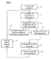
- FIG 4
- einen Prozessablauf zur Identifizierung der Automatisierungskomponenten.
- FIG. 1
- a block diagram as a schematic representation of an automation system with a system for identifying the automation components,
- FIG. 2
- an embodiment of a system for identifying the automation components,
- FIG. 3
- a schematic representation of the interaction of an identification unit and a reading unit of a system for the identification of the automation components and
- FIG. 4
- a process flow to identify the automation components.
FIG 1 zeigt die Prinzipdarstellung eines Automatisierungssystems AS. Das Automatisierungssystem AS besteht aus Automatisierungskomponenten AK11..AK52, beispielsweise Sensoren, Aktoren und sonstigen Leitungskomponenten. Die Automatisierungskomponenten AK11..AK52 sind jeweils mit Peripheriegeräten PG1, PG2 verbunden, während die Peripheriegeräte PG1, PG2 wiederum mit einer Steuerungseinrichtung 4 gekoppelt sind. Als Anwenderschnittstelle dient ein Bedien- und Beobachtungssystem 5, welches mit der Steuerung 4 verbunden ist. Den Automatisierungskomponenten AK11..AK52 sind jeweils Identifikationseinheiten ID11..ID52 zugeordnet. Der Begriff "Automatisierungskomponente" wird dabei so umfassend verstanden, dass hierunter sowohl Sensoren, Aktoren, als auch Anschluss- und Leitungskomponenten einschließlich Kabeln etc. verstanden wird. Die Identifikationseinheiten ID11..ID52 weisen jeweils einen Speicher auf, in dem ein die Automatisierungskomponenten AK11..AK52 jeweils eindeutig identifizierender Identifikationscode gespeichert ist. Jede Automatisierungskomponente AK11..AK52 ist dabei durch einen eindeutigen und eigens ihr zugeordneten Identifikationscode gekennzeichnet. Die Identifikationseinheiten ID11..ID52 sind über Leseeinheiten LE, LE1, LE2 aktivierbar, die in den Peripheriegeräten PG1, PG2, und/oder in einem mobilen Bediengerät 14 angeordnet sind.1 shows the schematic diagram of an automation system AS. The automation system AS consists of automation components AK11..AK52, for example sensors, actuators and other line components. The automation components AK11..AK52 are each connected to peripheral devices PG1, PG2, while the peripheral devices PG1, PG2 are in turn coupled to a
Die Besonderheit des in FIG 1 dargestellten Automatisierungssystems AS besteht darin, dass jede angeschlossene Automatisierungskomponente AK11..AK52, beispielsweise ein Sensor, ein Aktor, ein Kabel etc. mit einer Identifikationseinheit ID11..ID52 ausgestattet ist. Die Identifikationseinheiten ID11..ID52 bestehen aus einer elektronischen Schaltung (z.B. einem RFID-Chip oder diskreten Schaltung) und einer galvanisch trennenden (induktiv, kapazitiv, funktechnisch) oder galvanisch leitenden Ankopplung an die zu identifizierende Komponente AK11..AK52. Die Aufgabe der Identifikationseinheit ID11..ID52 besteht darin, bei Aktivierung den in ihr jeweils gespeicherten Identifikationscode IC (vgl. Fig. 3) auszugeben. Dieser Identifikationscode ermöglicht eine eindeutige Identifikation der zugehörigen Komponente AK. Die Identifikationseinheit ID11..ID52 kann nachträglich an die Automatisierungskomponente angebracht werden oder bereits bei der Komponentenherstellung untrennbar mit dieser verbunden werden. Die Identifikationseinheit ID11..ID52 kann aktiv, wird aber im Regelfall passiv ausgebildet sein. Sie ist in diesem Fall ohne eigene Energieversorgung, damit wartungsfrei und wird nur bei Bedarf über die ohnehin vorhandenen Leitungen von der Peripheriebaugruppe PG1, PG2 mit Energie versorgt. Hierfür sind die Peripheriebaugruppen PG1, PG2 des Automatisierungssystems und/oder das mobile Bedien- und Beobachtungssystem 14 mit einer Leseeinheit LE, LE1, LE2 ausgestattet. Die Leseeinheiten LE1, LE2 der Peripheriebaugruppen PG1, PG2 können über eine galvanisch trennende (induktiv, kapazitiv, funktechnisch) oder galvanisch leitende Ankopplung selektiv an die einzelnen Peripheriekanäle der Peripheriebaugruppen PG1, PG2 angeschaltet werden. Die Aufgabe der Leseeinheiten LE, LE1, LE2 besteht im wesentlichen darin, die zur Versorgung der Identifikationseinheiten notwendige Energie in den jeweiligen Peripheriekanal einzuspeisen, hierdurch die Identifikationseinheiten ID11..ID52 der angeschlossenen Komponenten AK11..AK52 jeweils zu aktivieren und so die Identifikationscodes der angeschlossenen Komponenten AK11..AK52 abzufragen.The peculiarity of the automation system AS shown in FIG. 1 is that each connected automation component AK11..AK52, for example a sensor, an actuator, a cable, etc., is equipped with an identification unit ID11..ID52. The identification units ID11..ID52 consist of an electronic circuit (eg an RFID chip or discrete circuit) and a galvanically isolated (inductive, capacitive, radio-technical) or galvanically conductive coupling to the component AK11..AK52 to be identified. The task of the identification unit ID11..ID52 is to output the identification code IC stored in it (see FIG. This identification code allows a unique identification of the associated component AK. The identification unit ID11..ID52 can be retrofitted to the automation component or already inseparably connected to it during component production. The identification unit ID11..ID52 can be active, but will normally be passive. It is in this case without its own power supply, so that maintenance-free and is supplied only if necessary via the already existing lines of the peripheral module PG1, PG2 with energy. For this purpose, the peripheral modules PG1, PG2 of the automation system and / or the mobile operating and
Die Energie- und Datenübertragung erfolgt dabei kanalselektiv, wenn jeweils nur ein Kanal mit Energie versorgt wird. Die Energie- und Datenübertragung erfolgt dabei weitgehend leitungsgebunden über die vorhandene Sensor-/Aktor-Verkabelung. Nur lokal im Nahbereich der Ankopplungen können neben galvanisch leitenden auch galvanisch trennende Verfahren (kapazitiv, induktiv, funktechnisch) benutzt werden, um Einflüsse auf die Mess- bzw. Stellgrößen zu vermeiden. Mit Hilfe des in FIG 1 dargestellten Automatisierungssystems AS wird es somit möglich, bisher nicht erkennbare Komponenten nun eindeutig zu identifizieren. Dies ist eine grundlegende Voraussetzung für neue Systemeigenschaften mit hohen Kundennutzen. Das gezeigte System bzw. Verfahren ist umfassend und für alle anschließbaren Komponenten geeignet. Es sind keine zusätzlichen Leitungen für die Identifikation der Komponenten erforderlich. Je nach Kundenwunsch, kann die Identifizierung der Automatisierungskomponenten auch schrittweise eingeführt bzw. nachgerüstet werden. Neben einer eindeutigen Identifizierung ergibt sich durch die kanalselektive und leitungsgeführte Energie- und Datenübertragung auch automatisch die Zuordnung der Komponenten AK11..AK52 zu den Peripheriekanälen.The energy and data transmission is channel selective, if only one channel is supplied with energy. The energy and data transmission is largely conducted via the existing sensor / actuator cabling. Only locally in the vicinity of the couplings can be used in addition to galvanically conductive and galvanic separating methods (capacitive, inductive, radio technology) to avoid influences on the measurement or manipulated variables. With the aid of the automation system AS shown in FIG. 1, it is thus possible to unambiguously identify previously unrecognizable components. This is a fundamental requirement for new system properties with high customer benefits. The system or method shown is comprehensive and suitable for all connectable components. There are no additional lines for the identification of the components required. Depending on the customer's requirements, the identification of the automation components can also be gradually introduced or retrofitted. In addition to a clear identification, the channel-selective and conducted energy and data transmission automatically results in the assignment of the components AK11..AK52 to the peripheral channels.
FIG 2 zeigt ein Ausführungsbeispiel eines Identifizierungssystems 1 zur Identifizierung von Automatisierungskomponenten AK11..AK72. Dabei sind nur die im Zusammenhang mit dem System zur Identifizierung erforderlichen Bestandteile dargestellt. Das Identifizierungssystem 1 besteht im wesentlichen aus einer Leseeinheit LE, die über Schalter S11..S72 jeweils mit Peripheriekanälen PK1..PK7 verbindbar ist. Die Leseeinheit LE ist beispielsweise Bestandteil einer Peripheriebaugruppe PG, wie dies bereits im Zusammenhang mit FIG 1 erläutert wurde. An die Klemmen K11..K72 der Peripheriekanäle PK1..PK7 sind jeweils Automatisierungskomponenten AK11..AK72 angeschlossen. Bei der Automatisierungskomponente AK11 handelt es sich beispielsweise um einen Temperatursensor, der über eine Datenleitung AK12, eine Komponentenanschlussdose AK13 und eine weitere Anschlussleitung AK14 an die Klemmen K11, K12 des Peripheriekanals PK1 der Peripheriebaugruppe PG angeschlossen ist. Die Klemmen K13..K14 sind ebenfalls mit der Komponentenanschlussdose AK13 verbunden bzw. mit der Leseeinheit verbindbar. Bei der Automatisierungskomponente AK31 handelt es sich um eine Widerstandsmesskomponente als Sensor, der über eine Datenleitung AK32 an den Peripheriekanal PK3 der Peripheriebaugruppe PG angeschlossen bzw. mit der Leseeinheit LE über die Leseschalter S31, S32 verbindbar ist.2 shows an embodiment of an
Als weitere Beispiele sind in FIG 2 beispielsweise eine Strommesskomponente AK41, eine Spannungsmesskomponente AK51, ein als Relais ausgebildeter Aktor AK61 sowie als weitere Automatisierungskomponente ein Ventil AK71 dargestellt. Den Automatisierungskomponenten AK11..AK72 des in FIG 2 dargestellten Identifikationssystems 1 sind jeweils Identifikationseinheiten ID zugeordnet. An dieser Stelle sei erwähnt, dass der Begriff Automatisierungskomponente AK bei dem in FIG 2 dargestellten Ausführungsbeispiel sowohl für die Sensoren AK11, AK31, AK41, AK51, wie auch für die Aktoren AK61, AK71 sowie für die Leitungskomponenten AK12, AK13, AK14 usw. verwendet wird.2, for example, a current measuring component AK41, a voltage measuring component AK51, an actuator AK61 designed as a relay, and a valve AK71 as a further automation component are shown as further examples. The automation components AK11..AK72 of the
Eine weitere Besonderheit des in FIG 2 dargestellten Identifikationssystems 1 besteht darin, dass in den in den Automatisierungskomponenten AK11..AK72 bzw. in den Identifikationseinheiten ID11..ID72 gespeicherten Identifizierungscodes jeweils eine komponentenspezifische Information gespeichert ist. Diese komponentenspezifische Information beinhaltet beispielsweise eine hierarchische Informationsgliederung in Komponentenklassen C1 für Sensoren, C2 für Aktoren, C3 für Thermokabel, C4 für Zubehör und C5 für Kabel. Der in den Identifikationseinheiten ID gespeicherte Identifizierungscode kann darüber hinaus weitere Klassifizierungen wie beispielsweise Komponentenart, z.B. bei Klasse: Sensor, Thermoelement /Thermowiderstand etc., Typ, Hersteller und gegebenenfalls weitere Informationsfelder bis hin zum Ausbau in Form eines elektronischen Datenblatts beinhalten. Die Codierung der Information des Identifizierungscodes ist im Prinzip dabei frei wählbar, kann sich aber für eine breite Marktabdeckung auch an existierenden Standards, wie beispielsweise dem Electronic Product Codes orientieren. Die Aktivierung der Identifikationseinheiten ID kann auf zwei Arten erfolgen:A further special feature of the
Durch bloßes Anlegen der Energieversorgung - in diesem Fall sendet die Identifikationseinheit ID ihren Identifikationscode bei Erreichen eines ausreichenden Versorgungspegels selbsttätig aus. In der Regel erfordert dies eine sogenannte Multitagfähigkeit der Leseeinheit. Eine weitere Möglichkeit besteht darin, ein selektives Ansprechen der Automatisierungskomponenten AK.. durchzuführen, z.B. durch Abfrage der jeweiligen Komponentenklasse, beispielsweise der Komponentenklasse C1 für Sensoren. In diesem Fall sendet die Identifikationseinheit ID ihren Identifikationscode nur dann aus, wenn sie das entsprechende Abfragekriterium der entsprechenden Komponentenklasse erfüllt, d.h. der Komponentenklasse Sensor C1 angehört. Hierdurch sind auch ohne aufwändige Multitagfähigkeit mehrere Komponenten an einem Peripheriekanal identifizierbar bzw. Detailinformationen einer Komponente selektiv abfragbar.By merely applying the power supply - in this case, the identification unit ID sends out its identification code automatically when a sufficient supply level is reached. As a rule, this requires a so-called multitageability of the reading unit. Another possibility is to perform a selective response of the automation components AK .., e.g. by querying the respective component class, for example the component class C1 for sensors. In this case, the identification unit ID sends out its identification code only if it fulfills the corresponding query criterion of the corresponding component class, i. belongs to the component class Sensor C1. As a result, multiple components on a peripheral channel can be identified or detailed information of a component can be selectively queried even without complex multi-tag capability.
Das Identifikationssystem 1 kann beispielsweise beim Einschalten bzw. beim Hochfahren einer Anlage für jede Peripheriebaugruppe selbständig einen Identifikationslauf der angeschlossenen Sensoren, Aktoren, Leitungen und Zubehörkomponenten durchführen. Hierzu wird für jeweils einen einzelnen Peripheriekanal im wesentlichen folgende Prozedur durchlaufen:
- Anschalten der Leseeinheit an den Peripheriekanal,
- Energieeinspeisung in den Periepheriekanal,
- Aktivieren der Identifikationseinheiten, Abfragen der Identifikationscodes,
- Energieeinspeisung beenden,
- Trennen der Leseeinheit vom Peripheriekanal.
- Switching on the reading unit to the peripheral channel,
- Energy input into the periepheric channel,
- Activating the identification units, querying the identification codes,
- End energy feed,
- Disconnecting the reader from the peripheral channel.
Diese Prozedur wird sequenziell für jeden der vorhandenen Peripheriekanäle einer Peripheriebaugruppe durchlaufen. Nach Abschluss des Identifikationslaufs lässt sich anhand der Identifikationscodes die Außenbeschaltung eines Peripheriekanals eindeutig rekonstruieren und für Plausibilitätsüberprüfung, Konformitätsüberprüfung mit der projektierten Anlagenkonfiguration, Autokonfiguration, Sensoradaption etc. verwenden. Ist die Leseeinheit beispielsweise in ein mobiles Bediengerät integriert, so kann das Verfahren auch bei der Installation und Wartung vor Ort für die Beschaltungsidentifikation eines einzelnen Peripheriekanals benutzt werden.This procedure is run sequentially for each of the peripheral channels present on an I / O board. After completion of the identification run, the external circuitry of a peripheral channel can be unambiguously reconstructed on the basis of the identification codes and used for plausibility check, conformity check with the configured system configuration, autoconfiguration, sensor adaptation, etc. If the reading unit is integrated, for example, in a mobile operating device, then the method can also be used during installation and maintenance on site for the wiring identification of a single peripheral channel.
FIG 3 zeigt eine Prinzipdarstellung für das Zusammenwirken einer Identifikationseinheit ID und einer Leseeinheit LE eines Systems 1 zur Identifizierung der Automatisierungskomponenten. In FIG 3 ist dabei nochmals vereinfachend eine Peripheriebaugruppe PG dargestellt, die mit einer Automatisierungskomponente AK kommuniziert. Der Peripheriebaugruppe PG ist über eine Kommunikationsschnittstelle 12 eine Leseeinheit LE zugeordnet, während der Automatisierungskomponente AK über eine weitere Kommunikationsschnittstelle 8 eine Identifikationseinheit ID zugeordnet ist. Die Identifikationseinheit ID weist einen Speicher 9 zur Speicherung eines Identifizierungscodes IC für die Automatisierungskomponente AK auf. Bezüglich der Funktionsweise des Identifikationssystems 1 wird zur Vermeidung von Wiederholungen auf die bereits im Zusammenhang mit den FIG 1 und 2 erfolgten Ausführungen verwiesen.3 shows a schematic representation of the interaction of an identification unit ID and a reading unit LE of a
FIG 4 zeigt einen beispielhaften Prozessablauf zur Identifizierung der Automatisierungskomponenten, wie sie beispielsweise im Zusammenhang mit den in den FIG 1 bis 3 Identifikationssystemen zum Einsatz kommen kann. Die Prozedur beginnt mit einem Einschalten der Leseeinheit im Schritt 20, als nächster Prozessschritt erfolgt ein Anschalten der Leseeinheit an einen Peripheriekanal n im Prozessschritt 21, in einem Prozessschritt 22 erfolgt ein Einspeisen von Energie in den Peripheriekanal. Optional kann, wie im Zusammenhang mit FIG 2 erläutert wurde, im Prozessschritt 23 auch eine selektive Ansprache von vorgebbaren Identifizierungsklassen und/oder sonstigen Identifizierungsmerkmalen erfolgen. Im folgenden Prozessschritt 24 erfolgt ein Aktivieren der Identifikationseinheiten, d.h. ein Senden des Identifikationscodes durch die Identifikationseinheit. Im folgenden Prozessschritt 25 empfängt die Leseeinheit den Identifikationscode, beispielsweise durch die mit dem Peripheriekanal bzw. mit dem mobilen Bediengerät bestehende ohnehin vorhandene Datenverbindung. Im Prozessschritt 26 erfolgt ein Trennen der Leseeinheit vom Peripheriekanal. Mit Hilfe des Blocks 27 wird visualisiert, dass die in FIG 4 dargestellte Prozedur für sämtliche vorhandenen Peripheriekanäle durchlaufen werden kann.FIG. 4 shows an exemplary process sequence for identifying the automation components, as may be used, for example, in connection with the identification systems shown in FIGS. The procedure begins when the reading unit is switched on in
Zusammenfassend betrifft die Erfindung somit ein System und ein Verfahren zur Identifizierung von passiven Automatisierungskomponenten, insbesondere von Sensoren, Aktoren und Leitungskomponenten. Hierzu wird jede zu identifizierende Komponente (Sensor, Aktor, Kabel, Kompensationsdose, etc.) mit einer Identifikationseinheit ausgestattet, in der ein Identifikationscode zur Identifizierung der Automatisierungskomponente gespeichert ist und die diesen bei Aktivierung aussendet bzw. ausliest. Die Identifikationseinheit besteht bevorzugt aus einer elektronischen Schaltung (z.B. RFID-Chip oder diskrete Schaltung) und einer galvanisch trennenden (induktiv, kapazitiv, funktechnisch) oder galvanisch leitenden Ankopplung, an die zu identifizierende Komponente. Die Identifikationseinheit kann nachträglich an eine Komponente angebracht werden oder bereits bei der Komponentenherstellung untrennbar mit dieser verbunden werden.In summary, the invention thus relates to a system and a method for identifying passive automation components, in particular of sensors, actuators and line components. For this purpose, each component to be identified (sensor, actuator, cable, compensation box, etc.) is equipped with an identification unit in which an identification code for the identification of the automation component is stored and which transmits or reads this out upon activation. The identification unit preferably consists of an electronic circuit (eg RFID chip or discrete circuit) and a galvanically isolated (inductive, capacitive, radio-technical) or electrically conductive coupling to the component to be identified. The identification unit can be subsequently attached to a component be inseparable from it during component manufacturing.
Claims (24)
- System for identifying automation components (AK), in particular sensors, actuators and line components of an automation system (AS)- with an identification unit (ID) assigned respectively to an automation component (AK),- with an identification code (IC) for identifying the respective automation component (AK) stored in the identification unit (ID) and- with a read unit (LE) for reading the identification code (IC) from the identification unit (ID),characterised in that
the system has means for activating the identification unit(s) (ID) in the manner that selective addressing of a predefinable component class causes the identification unit (ID) assigned to the predefinable component class to output its identification code (IC). - System according to claim 1,
characterised in that the read unit (LE) is provided for connection to a peripheral module (2) and/or an operating device (14) of the automation system (AS). - System according to one of claims 1 or 2,
characterised in that the read unit (LE) is provided to activate the identification units (ID) and/or to scan the identification codes (IC) of the connected automation components (AK). - System according to one of claims 1 to 3,
characterised in that the read unit (LE) is provided to inject the energy required to supply the identification units (ID) into the peripheral channel (PK). - System according to one of claims 1 to 4,
characterised in that the identification unit (ID) is made up of an electronic circuit and a connection to the automation component (AK) to be identified. - System according to one of claims 1 to 5,
characterised in that the identification unit (ID) is configured as a separate unit for subsequent mounting on an automation component (AK) or as a unit connected inseparably to the automation component (AK). - System according to one of claims 1 to 6,
characterised in that the system has means for activating the identification unit(s) (ID) in the manner that application of the energy supply causes the identification unit (ID) to output its identification code (IC) automatically when an adequate supply level is reached. - Identification unit (ID) for a system for identifying automation components, in particular sensors, actuators and line components of an automation system (AS), with an identification unit (ID) being provided for assignment to an automation component (AK) in each instance,- with an identification code (IC) for identifying the respective automation component (AK) stored in the identification unit and- with a transmit unit for transmitting the identification code (IC) from the identification unit (ID) to a read unit (LE), characterised in that
the identification unit (ID) has means for activating the transmit unit in the manner that selective addressing of a predefinable component class causes the identification unit (ID) assigned to the predefinable component class to output its identification code (IC). - Identification unit (ID) according to claim 8,
characterised in that the identification unit (ID) is made up of an electronic circuit and a connection to the automation component (AK) to be identified. - Identification unit (ID) according to one of claims 8 or 9,
characterised in that the identification unit (ID) is configured as a separate unit for subsequent mounting on an automation component (AK) or as a unit connected inseparably to the automation component (AK). - Identification unit (ID) according to one of claims 8 to 10,
characterised in that the transmit unit of the identification unit (ID) is configured such that the identification unit (ID) outputs its identification code (IC) automatically when an adequate supply level is reached. - Read unit (LE) for a system for identifying automation components (AK), in particular sensors, actuators and line components of an automation system (AS), with the read unit (LE) being provided for connection to a peripheral module (PG) and/or an operating device (14) of the automation system (AS), in particular for integration into the peripheral module (PG) and/or the operating device (14), and having means for receiving an identification code (IC) output by an identification unit (ID) of an automation component (AK)
characterised in that the read unit (LE) has means for activating the identification unit(s) (ID) in the manner that selective addressing of a predefinable component class causes the identification unit (ID) assigned to the predefinable component class to output its identification code (IC). - Read unit (LE) according to claim 12,
characterised in that the read unit (LE) is provided to activate the identification units (ID) and/or to scan the identification codes (IC) of the connected automation components (AK)). - Read unit (LE) according to one of claims 12 or 13,
characterised in that the read unit (LE) is provided to inject the energy required to supply the identification units (ID) into the peripheral channel (PK). - Read unit (LE) according to one of claims 12 to 14,
characterised in that the read unit (LE) has means for activating the identification unit(s) (ID) in the manner that application of the energy supply causes the identification unit (ID) to output its identification code (IC) automatically when an adequate supply level is reached. - Method for identifying automation components (AK), in particular sensors, actuators and line components of an automation system (AS) with the following steps:- assignment of an identification unit (ID) respectively to an automation component (AK),- storage of an identification code (IC) for identifying the respective automation component (AK) in a storage unit of the identification unit (ID) and- program-controlled and/or user-controlled reading of the identification code (IC) from the identification unit (ID),characterised in that the identification unit(s) (ID) are activated in the manner that selective addressing of a predefinable component class causes the identification unit (ID) assigned to the predefinable component class to output its identification code (IC).
- Method according to claim 16,
characterised in that the read unit (LE) is connected to a peripheral module (PG) and/or an operating device (14) of the automation system (AS) or is integrated in the peripheral module (PG) and/or in the operating device (14). - Method according to one of claims 16 or 17,
characterised in that the read unit (LE) activates the identification units (ID) and/or reads the identification codes (IC) of the connected automation components (AK). - Method according to one of claims 16 to 18,
characterised in that the read unit (LE) injects the energy required to supply the identification units (ID) into the peripheral channel (PK). - Method according to one of claims 16 to 19,
characterised in that the identification unit (ID) is made up of an electronic circuit and a connection to the automation component (AK) to be identified. - Method according to one of claims 16 to 20,
characterised in that the identification unit (ID) is configured as a separate unit for subsequent mounting on an automation component (AK) or as a unit connected inseparably to the automation component (AK) - Method according to one of claims 16 to 21,
characterised in that the identification unit(s) (ID) are activated in the manner that application of the energy supply causes the identification unit (ID) to output its identification code (IC) automatically when an adequate supply level is reached. - Method according to one of claims 16 to 22,
characterised in that when the automation system is switched on, the peripheral module (PG) automatically carries out an identification process for the connected automation components (AK), with the following procedure being followed for a peripheral channel (PK) in each instance:- connection of the read unit (LE) to the peripheral channel (PKn),- injection of energy into the peripheral channel (PKn),- activation of the identification units (ID) and scanning of the identification codes (IC),- termination of the energy injection and- separation of the read unit (LE) from the peripheral channel (PKn). - Method according to claim 23,
characterised in that the procedure is followed sequentially for each of the existing N peripheral channels (PK) of a peripheral module (PG).
Applications Claiming Priority (2)
| Application Number | Priority Date | Filing Date | Title |
|---|---|---|---|
| DE10335035A DE10335035A1 (en) | 2003-08-01 | 2003-08-01 | System and method for identifying automation components |
| PCT/EP2004/007587 WO2005015330A1 (en) | 2003-08-01 | 2004-07-09 | System and method for the identification of automation components |
Publications (2)
| Publication Number | Publication Date |
|---|---|
| EP1649331A1 EP1649331A1 (en) | 2006-04-26 |
| EP1649331B1 true EP1649331B1 (en) | 2007-04-25 |
Family
ID=34111782
Family Applications (1)
| Application Number | Title | Priority Date | Filing Date |
|---|---|---|---|
| EP04740866A Active EP1649331B1 (en) | 2003-08-01 | 2004-07-09 | System and method for the identification of automation components |
Country Status (5)
| Country | Link |
|---|---|
| US (1) | US7551084B2 (en) |
| EP (1) | EP1649331B1 (en) |
| CN (2) | CN101551668A (en) |
| DE (2) | DE10335035A1 (en) |
| WO (1) | WO2005015330A1 (en) |
Families Citing this family (20)
| Publication number | Priority date | Publication date | Assignee | Title |
|---|---|---|---|---|
| DE102004050383A1 (en) * | 2004-10-15 | 2006-04-27 | Siemens Ag | Transfer of data to and from automation components |
| DE102005027671A1 (en) * | 2005-06-15 | 2006-12-28 | Siemens Ag | System and method for RFID-supported system configuration |
| EP2025445B1 (en) * | 2005-09-12 | 2013-05-29 | Paul Müller GmbH & Co. KG Unternehmensbeteiligungen | Spindle with data recording element |
| DE502005003131D1 (en) * | 2005-11-25 | 2008-04-17 | Siemens Ag | Automation system with a connected RFID-identified sensor or actuator |
| DE202006021238U1 (en) | 2006-08-25 | 2014-01-29 | Baumer Hhs Gmbh | hot glue application system |
| ATE461369T1 (en) * | 2007-10-24 | 2010-04-15 | Festo Ag & Co Kg | FLUIDIC VALVE ARRANGEMENT HAVING AT LEAST ONE SOLENOID VALVE AND AN IDENTIFICATION DATA MEMORY |
| US9818071B2 (en) | 2007-12-21 | 2017-11-14 | Invention Science Fund I, Llc | Authorization rights for operational components |
| US9626487B2 (en) * | 2007-12-21 | 2017-04-18 | Invention Science Fund I, Llc | Security-activated production device |
| DE212009000026U1 (en) * | 2008-01-31 | 2010-10-14 | Khozyainov, Boris A. | Connection sensor for identifying a connection point in a control panel |
| EP2208120A1 (en) | 2008-03-22 | 2010-07-21 | Festo AG & Co. KG | Automation system comprising several automation components forming an assembly |
| DE102008027846B4 (en) * | 2008-06-11 | 2019-06-27 | Endress+Hauser SE+Co. KG | Device for automatically detecting the topology of the individual components of a process plant in automation technology |
| JP4586092B2 (en) * | 2008-12-04 | 2010-11-24 | ファナック株式会社 | Robot system with multiple robot mechanisms |
| DE102009029933A1 (en) * | 2009-06-19 | 2010-12-23 | Honeywell Technologies S.A.R.L. | Building Management System |
| EP2775425B1 (en) * | 2013-03-07 | 2017-10-04 | General Electric Technology GmbH | A method for identifying an electrical equipment electronic device |
| JP6402882B2 (en) * | 2013-09-19 | 2018-10-10 | パナソニックIpマネジメント株式会社 | Component mounting system and component mounting method |
| EP2924521B1 (en) * | 2014-03-27 | 2020-06-03 | Siemens Aktiengesellschaft | Distributed control system with naming of peripheral modules by the users |
| CN105224304B (en) * | 2014-07-02 | 2018-12-04 | 北京泺喜文化传媒有限公司 | The control method and device that the page is shown |
| CN104503376A (en) * | 2014-11-04 | 2015-04-08 | 北京泺喜文化传媒有限公司 | Robot controller having identification function and identification method of robot controller |
| DE102016224158A1 (en) * | 2016-12-05 | 2018-06-07 | Continental Automotive Gmbh | Method for configuring devices and corresponding devices |
| DE102019101126A1 (en) * | 2019-01-17 | 2020-07-23 | Valeo Schalter Und Sensoren Gmbh | Sensor, initialization method and communication system |
Family Cites Families (19)
| Publication number | Priority date | Publication date | Assignee | Title |
|---|---|---|---|---|
| US5430441A (en) * | 1993-10-12 | 1995-07-04 | Motorola, Inc. | Transponding tag and method |
| US5910776A (en) * | 1994-10-24 | 1999-06-08 | Id Technologies, Inc. | Method and apparatus for identifying locating or monitoring equipment or other objects |
| US5745049A (en) * | 1995-07-20 | 1998-04-28 | Yokogawa Electric Corporation | Wireless equipment diagnosis system |
| US6046676A (en) * | 1997-11-14 | 2000-04-04 | International Business Machines Corporation | Self powered electronic memory identification tag with dual communication ports |
| US6249227B1 (en) * | 1998-01-05 | 2001-06-19 | Intermec Ip Corp. | RFID integrated in electronic assets |
| US6476708B1 (en) * | 1998-03-20 | 2002-11-05 | Hid Corporation | Detection of an RFID device by an RF reader unit operating in a reduced power state |
| JP3780697B2 (en) * | 1998-05-13 | 2006-05-31 | 株式会社デンソー | Vehicle diagnostic system |
| GB2357611B (en) * | 1999-12-21 | 2004-06-02 | Ibm | Electronic location tag |
| DE60133378T2 (en) * | 2000-04-20 | 2009-01-08 | Cogiscan Inc., Bromont | AUTOMATIC MANUFACTURING SYSTEM |
| JP3578057B2 (en) * | 2000-07-06 | 2004-10-20 | 株式会社日立製作所 | ID management system |
| US20020120651A1 (en) * | 2000-09-12 | 2002-08-29 | Lingomotors, Inc. | Natural language search method and system for electronic books |
| WO2003017015A1 (en) * | 2001-07-31 | 2003-02-27 | Voith Turbo Gmbh & Co. Kg | Method for identifying modules or modular units and system for identifying and/or diagnosing a module or a modular unit comprising a plurality of individual components |
| US7035877B2 (en) * | 2001-12-28 | 2006-04-25 | Kimberly-Clark Worldwide, Inc. | Quality management and intelligent manufacturing with labels and smart tags in event-based product manufacturing |
| US6917847B2 (en) * | 2003-07-18 | 2005-07-12 | Motorola, Inc. | Method and apparatus for design for manufacturing |
| US7571539B2 (en) * | 2003-08-26 | 2009-08-11 | Panasonic Corporation | Component verification method and apparatus |
| US6847856B1 (en) * | 2003-08-29 | 2005-01-25 | Lucent Technologies Inc. | Method for determining juxtaposition of physical components with use of RFID tags |
| US8019455B2 (en) * | 2004-05-17 | 2011-09-13 | Panasonic Corporation | Component mounting order deciding method and component mounting order deciding apparatus |
| US7266518B2 (en) * | 2005-12-29 | 2007-09-04 | Kimberly-Clark Worldwide, Inc. | Spare parts inventory management |
| US7526582B2 (en) * | 2006-11-30 | 2009-04-28 | International Business Machines Corporation | Identifying a cable with a connection location |
-
2003
- 2003-08-01 DE DE10335035A patent/DE10335035A1/en not_active Ceased
-
2004
- 2004-07-09 WO PCT/EP2004/007587 patent/WO2005015330A1/en active IP Right Grant
- 2004-07-09 EP EP04740866A patent/EP1649331B1/en active Active
- 2004-07-09 CN CNA2009101386003A patent/CN101551668A/en active Pending
- 2004-07-09 CN CNB200480022081XA patent/CN100555135C/en active Active
- 2004-07-09 DE DE502004003630T patent/DE502004003630D1/en active Active
-
2006
- 2006-02-01 US US11/346,857 patent/US7551084B2/en active Active
Non-Patent Citations (1)
| Title |
|---|
| None * |
Also Published As
| Publication number | Publication date |
|---|---|
| EP1649331A1 (en) | 2006-04-26 |
| CN101551668A (en) | 2009-10-07 |
| DE502004003630D1 (en) | 2007-06-06 |
| WO2005015330A1 (en) | 2005-02-17 |
| CN100555135C (en) | 2009-10-28 |
| CN1829947A (en) | 2006-09-06 |
| US20060125607A1 (en) | 2006-06-15 |
| US7551084B2 (en) | 2009-06-23 |
| DE10335035A1 (en) | 2005-03-03 |
Similar Documents
| Publication | Publication Date | Title |
|---|---|---|
| EP1649331B1 (en) | System and method for the identification of automation components | |
| DE102013207760B4 (en) | Electrical interface module | |
| AT504973B1 (en) | SYSTEM AND METHOD FOR CONTROLLING BUS-LINKED DEVICES THROUGH AN OPEN FIELDBUS | |
| DE102010037262B4 (en) | Integrated bus control and power supply device for use in a process control system | |
| EP1174781B1 (en) | Signal transmission apparatus | |
| DE10249414A1 (en) | Electronic communications-compatible pluggable connector unit e.g. for product data handling, has component-specific information electronically stored by data carrier | |
| EP0730803A1 (en) | Device for exchanging data and processes for operating it | |
| WO2009006916A1 (en) | System and method for controlling bus-networked devices via an open field bus | |
| DE102007025852B3 (en) | Monitoring device for detecting an incorrect addressing of an actuator-sensor interface slave | |
| DE10037968B4 (en) | Electric drive with engine identification and engine identification procedure | |
| DE102009055247A1 (en) | Arrangement with a higher-level control unit and at least one connectable to the control unit intelligent field device | |
| EP1840684A1 (en) | Automation device and system with components communicating connectionless (radio frequency) using detachable radio module FM | |
| DE102004011457B4 (en) | Actuator and method for operating an actuator | |
| EP3647600B1 (en) | Identification of an electrically connected peripheral | |
| EP1672446B1 (en) | Secure Input/Ouput assembly for a controller | |
| EP2992392A1 (en) | Electrical interface module | |
| DE102013211772A1 (en) | Method and device for exchanging data in a motor vehicle for operating an actuator, preferably an automated friction clutch and / or an automated transmission | |
| EP3557598A1 (en) | Safety switch | |
| DE102004010003A1 (en) | Automation system and method for detecting and correcting connection errors | |
| EP2778811A1 (en) | Device for an AS interface system | |
| WO2016046352A1 (en) | System with electronic modules which can be arranged one next to the other | |
| DE19844797C2 (en) | Manufacturing and / or assembly device | |
| EP3126991B1 (en) | Electrical interface module | |
| EP2208120A1 (en) | Automation system comprising several automation components forming an assembly | |
| EP1031041A1 (en) | Device for checking an electric drive |
Legal Events
| Date | Code | Title | Description |
|---|---|---|---|
| PUAI | Public reference made under article 153(3) epc to a published international application that has entered the european phase |
Free format text: ORIGINAL CODE: 0009012 |
|
| 17P | Request for examination filed |
Effective date: 20060119 |
|
| AK | Designated contracting states |
Kind code of ref document: A1 Designated state(s): DE FR GB IT |
|
| DAX | Request for extension of the european patent (deleted) | ||
| RBV | Designated contracting states (corrected) |
Designated state(s): DE FR GB IT |
|
| GRAP | Despatch of communication of intention to grant a patent |
Free format text: ORIGINAL CODE: EPIDOSNIGR1 |
|
| GRAC | Information related to communication of intention to grant a patent modified |
Free format text: ORIGINAL CODE: EPIDOSCIGR1 |
|
| GRAS | Grant fee paid |
Free format text: ORIGINAL CODE: EPIDOSNIGR3 |
|
| GRAA | (expected) grant |
Free format text: ORIGINAL CODE: 0009210 |
|
| AK | Designated contracting states |
Kind code of ref document: B1 Designated state(s): DE FR GB IT |
|
| REG | Reference to a national code |
Ref country code: GB Ref legal event code: FG4D Free format text: NOT ENGLISH |
|
| REF | Corresponds to: |
Ref document number: 502004003630 Country of ref document: DE Date of ref document: 20070606 Kind code of ref document: P |
|
| GBT | Gb: translation of ep patent filed (gb section 77(6)(a)/1977) |
Effective date: 20070605 |
|
| ET | Fr: translation filed | ||
| PLBE | No opposition filed within time limit |
Free format text: ORIGINAL CODE: 0009261 |
|
| STAA | Information on the status of an ep patent application or granted ep patent |
Free format text: STATUS: NO OPPOSITION FILED WITHIN TIME LIMIT |
|
| 26N | No opposition filed |
Effective date: 20080128 |
|
| REG | Reference to a national code |
Ref country code: FR Ref legal event code: PLFP Year of fee payment: 13 |
|
| REG | Reference to a national code |
Ref country code: FR Ref legal event code: PLFP Year of fee payment: 14 |
|
| REG | Reference to a national code |
Ref country code: FR Ref legal event code: PLFP Year of fee payment: 15 |
|
| PGFP | Annual fee paid to national office [announced via postgrant information from national office to epo] |
Ref country code: IT Payment date: 20230725 Year of fee payment: 20 Ref country code: GB Payment date: 20230807 Year of fee payment: 20 |
|
| PGFP | Annual fee paid to national office [announced via postgrant information from national office to epo] |
Ref country code: FR Payment date: 20230720 Year of fee payment: 20 Ref country code: DE Payment date: 20230808 Year of fee payment: 20 |