EP1649227B1 - Contact freezer - Google Patents
Contact freezer Download PDFInfo
- Publication number
- EP1649227B1 EP1649227B1 EP04748981A EP04748981A EP1649227B1 EP 1649227 B1 EP1649227 B1 EP 1649227B1 EP 04748981 A EP04748981 A EP 04748981A EP 04748981 A EP04748981 A EP 04748981A EP 1649227 B1 EP1649227 B1 EP 1649227B1
- Authority
- EP
- European Patent Office
- Prior art keywords
- conveyor belt
- metal sheet
- groups
- refrigerating unit
- inlets
- Prior art date
- Legal status (The legal status is an assumption and is not a legal conclusion. Google has not performed a legal analysis and makes no representation as to the accuracy of the status listed.)
- Expired - Lifetime
Links
Images


Classifications
-
- F—MECHANICAL ENGINEERING; LIGHTING; HEATING; WEAPONS; BLASTING
- F25—REFRIGERATION OR COOLING; COMBINED HEATING AND REFRIGERATION SYSTEMS; HEAT PUMP SYSTEMS; MANUFACTURE OR STORAGE OF ICE; LIQUEFACTION SOLIDIFICATION OF GASES
- F25D—REFRIGERATORS; COLD ROOMS; ICE-BOXES; COOLING OR FREEZING APPARATUS NOT OTHERWISE PROVIDED FOR
- F25D13/00—Stationary devices, e.g. cold-rooms
- F25D13/06—Stationary devices, e.g. cold-rooms with conveyors carrying articles to be cooled through the cooling space
- F25D13/062—Stationary devices, e.g. cold-rooms with conveyors carrying articles to be cooled through the cooling space with refrigerated conveyors
Definitions
- the present invention relates to a contact freezer for food products. More specifically, the invention concerns such a contact freezer for freezing a surface layer of the food products. The final freezing of the food products can then suitably take place in a freezer using convection cooling of cold air.
- Contact freezers for partial or complete freezing of food products are known in various designs. As a rule they use a conveyor belt on which the products are conveyed through a cooling station where the temperature of the belt is lowered enough for the products while passing therethrough to be frozen at least in a surface layer in contact with the conveyor belt.
- the conveyor belt can be cooled indirectly by its underside at the cooling station contacting the upper side of a refrigerating unit which in turn is directly cooled in a suitable manner.
- a refrigerating unit which in turn is directly cooled in a suitable manner.
- This lubricating liquid reduces friction, which is otherwise increased due to the curvature, between the conveyor belt and the refrigerating unit, but it also causes the same problems as in the above case with direct cooling of the conveyor belt.
- refrigerating unit for a contact freezer are known from, inter alia, EP 0 759 529 A2 , US-A-3,037,366 , US-A-3,528,257 , US-A-3,584,471 , US-A-4,205,536 and US-A-6,009,719 .
- a common feature of the known refrigerating units is a relatively complicated and thus expensive construction which after all exhibits a limited degree of efficiency.
- the object of the present invention therefore is to provide an effective contact freezer of a simpler construction.
- the invention provides a contact freezer for food products of the type that comprises a conveyor belt and a refrigerating unit, which has an upper side in contact with part of an underside of the conveyor belt and is adapted to refrigerate food products positioned on the conveyor belt as they pass over the refrigerating unit, so that a layer of the food products next to the conveyor belt is transferred to a frozen state.
- This contact freezer is characterised in that the conveyor belt consists of a flexible, non-metallic material, and the refrigerating unit comprises an upper metal sheet which is convexly curved in the travelling direction of the conveyor belt and which forms the upper side of the refrigerating unit with a surface which preferably consists of stainless steel in direct sliding contact with the conveyor belt during the movement thereof, a lower metal sheet which is arranged under the upper metal sheet with a gap thereto and which has a plurality of groups of inlets which are arranged alternately with a plurality of groups of outlets, sealing means for closing the gap round an area which comprises the groups of inlets and the groups of outlets, and means for feeding a coolant in a closed loop which comprises the parts of the area which are connected in parallel and located between the groups of inlets and the groups of outlets, which are arranged alternately with the groups of inlets.
- the invention thus provides a simple refrigerating unit, which by the bending of the upper metal sheet, resulting in surface smoothness, and the use of a flexible, non-metallic conveyor belt gives sufficiently good heat transfer over the boundary layer between them, without requiring the use of some kind of contact-creating liquid.
- the refrigerating unit also exhibits highly efficient refrigeration through the division of the cooling area into a plurality of partial areas to which the coolant is supplied in parallel, so that the difference between the maximum and minimum temperatures of the coolant in the total cooling area can be kept relatively small.
- a cold-rolled sheet of stainless steel particularly of austenitic, molybdenum-alloyed steel, such as Sandvik 1200 SA. It is essential for the surface smoothness that the material of the metal sheet should be resilient, which is the case with cold-rolled sheet.
- the upper metal sheet have good surface smoothness and also good thermal conductivity.
- a metal sheet of, for instance, aluminium or an aluminium alloy but also with a laminated metal sheet having a lower layer with excellent thermal conductivity and an upper layer with good wear properties and good sanitary properties.
- each group of inlets and each group of outlets comprise a plurality of openings arranged transversely to the travelling direction of the conveyor belt. This ensures substantially uniform cooling of the carrying surface of the conveyor belt and, thus, of the food products on the conveyor belt over the entire width thereof. However, it is possible to orient the inlets in a different manner relative to the outlets.
- Spacers are suitably arranged to determine the size of the gap and, in the preferred embodiment, they may comprise elements which are extended in the travelling direction of the conveyor belt and arranged between the upper metal sheet and the lower metal sheet. This ensures a substantially constant gap size over the entire area of the gap, which is essential for good distribution of the coolant flow.
- the size of the gap and the thickness of the upper metal sheet can be in the order of 1 mm, while the lower metal sheet can have a thickness of about 2 mm.
- the inlets By forming the inlets with, taken together, a substantially smaller opening area than twice the area of the gap cross-section adjacent to the inlets, and forming the outlets with, taken together, a larger opening area than twice the area of the gap cross-section adjacent to the outlets, the pressure is reduced to atmospheric pressure adjacent to the outlets, and the pressure drop occurs mainly adjacent to the inlets. This gives the advantage that lower demands can be placed on the seal round the gap.
- the upper and lower metal sheets also form a lid for a vessel, which is arranged to receive the coolant flowing out of the outlets and to feed this through a bottom outlet.
- the upper and lower metal sheets are preferably supported by two supports extended in the travelling direction of the belt and having a convex profile, which abut against the lower metal sheet at the lateral edges thereof.
- the vessel can be supported in a stand, in which a first guide roller for the conveyor belt is mounted at a feed end of the refrigerating unit, and a second guide roller for the conveyor belt is mounted at a discharge end of the refrigerating unit.
- a third guide roller is mounted under the refrigerating unit.
- the product-carrying surface of the endless conveyor will not come into contact with anything else than the product, which is important from the sanitary point of view. Since condensation may form on the non-product-carrying surface of the conveyor belt after passing the guide roller at the discharge end, a drying device for this surface is also suitably arranged along the return run of the conveyor belt between the discharge end and the feed end.
- a contact freezer shown in Fig. 1 comprises a stand 1, a refrigerating unit 2 supported thereby and a conveyor belt 3 following a path determined by three guide rollers 4-6 and the upper side of the refrigerating unit 2.
- the guide roller 4 is more specifically arranged at a feed end of the contact freezer and constitutes the drive roller for the conveyor belt 3, the guide roller 5 is arranged at a discharge end of the contact freezer, and the guide roller 6 is arranged under the refrigerating unit 2.
- the motor for the drive roller can be arranged in the same or drive, in a conventional way, by pulleys using a drive belt (not shown).
- the guide roller 5 arranged at the discharge end of the contact freezer suitably has a much smaller diameter than the guide roller 4, thus allowing the products on the conveyor belt 3 to easily leave the same at the discharge end.
- the guide roller 6 is mounted in arms 7 which in turn are pivotally mounted in the stand 1 in such a manner that the weight of the guide roller 6 will tension the conveyor belt 3 in its path. If necessary, the belt tension of the conveyor belt 3 can be further increased by yet another force, for instance generated by a spring, being applied to the arms 7. Since the guide roller 6 is pivotally mounted in the stand 1, the conveyor belt 3 can easily be removed, for instance to be exchanged, by pivoting the guide roller 6 upwards. The belt tension is then released, thus allowing the conveyor belt 3 to be removed from the guide rollers 4 and 5 by lateral displacement.
- a conveyor belt passed over guide rollers may tend to move in the lateral direction.
- the guide roller 6 can then be used to guide the conveyor belt 3.
- Sensor means (not shown) can in this case be arranged to detect any lateral deviation of the conveyor belt.
- the information is supplied to a compensating means (not shown) which in response to said information is adapted to angle the guide roller to compensate for said deviation. It will be appreciated that it is also possible to arrange one of the guide rollers 4 and 5 to provide said belt guiding.
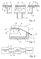
- the refrigerating unit 2 is shown in more detail in Figs 2-7 . It comprises a vessel 8 and a cooling sheet 9 which forms a lid for the vessel 8, and liquid pipes 10 and 11 for supplying coolant to the refrigerating unit 2 and discharging used coolant from the refrigerating unit 2.
- the vessel 8 may comprise a varying amount of coolant and thus eliminates the need for a special expansion vessel.
- the coolant can advantageously be a brine with a temperature of about -50°C for instance, which is circulated in a closed loop between the secondary side of a heat exchanger and the refrigerating unit 2, the primary side of the heat exchanger being cooled in a suitable manner by means of a refrigerator connected thereto, as schematically shown in Fig. 8 .
- a pump 52 used for circulating the coolant is arranged immediately after the refrigerating unit 2 in the closed loop, since this gives the lowest cooling temperature in the refrigerating unit 2 for a given evaporation temperature in the refrigerator.
- the vessel 8 has double walls 12 and 13, preferably of stainless steel, with an intermediate insulation 14 in the bottom 15 and also in the side walls 16, 17 and in the end walls 18, 19.
- the bottom 15 slopes towards a centrally arranged opening 20, which connects to the liquid pipe 11 for discharge of used brine back to the heat exchanger.
- Centrally in the bottom 15 there is also a tight lead-through 21 for the liquid pipe 10 for supplying brine from the heat exchanger.
- the vessel 8 is supported and fixed to the stand 1 by means of four supports 22 on its underside.
- a rail 23 is fixed by a plurality of brackets 24 and 25 at a distance from the inside of the side wall 16 and extends along the side wall 16 practically all the way to the end walls 18 and 19. As is evident from Figs 3 and 7 , it has a convex upper edge 26.
- a corresponding rail 27 is in the same way fixed by a plurality of brackets 28 and 29 at a distance from the inside of the side wall 17. Additional rails of this type can be arranged between the rails 23 and 27.
- the convexity of the rails 23, 27 can correspond to a curvature of 0.5-6% per unit of length, and still more preferred a curvature of 1-3% per unit of length.
- the cooling sheet 9 rests along its lateral edges on the rails 23, 27 and is kept fixed to them by means of screws 30 which through holes 31 in the cooling sheet 9 are inserted in threaded holes 32 in the brackets 24 and 28 respectively.
- the screws 30 do not engage the upper side of the cooling sheet 9 directly with their heads, but by the intermediary of a flat strip 33.
- the holes 31 have a larger diameter than the screws 30 so as to allow lateral movement of the cooling sheet in case of changes in temperature.
- the actual cooling sheet 9 consists of an upper metal sheet 34 and a lower metal sheet 35, between which a gap 36 forms by a plurality of elongate spacers 37 being arranged between the metal sheets 34 and 35.
- the elongate spacers 37 extend mainly in the travelling direction of the conveyor belt 3 over the cooling sheet 9 and are thus arranged with interspaces transversely to the travelling direction of the conveyor belt 3.
- the upper metal sheet 34 is bent downwards adjacent to the end wall 18 of the vessel 8 and is there fixed and sealed against a flange 38 of the end wall 18. The same applies to the end wall 19.
- the gap 36 is outwardly laterally defined by a seal 39 which extends in an endless manner along and inside the periphery of the cooling sheet 9, as is evident from Figs 5 and 7 , and is pressed together between the metal sheets 34 and 35 when tightening the screws 30.
- the lower metal sheet 35 has five groups of inlets 40, each group consisting of a plurality of openings arranged in a row transversely to the travelling direction of the conveyor belt 3 and inside the seal 39 over the entire width of the lower metal sheet 35.
- These five groups of inlets 40 are arranged alternately with six groups of outlets 41, where each group also consists of a plurality of openings arranged in a row transversely to the travelling direction of the conveyor belt 3 and inside the seal 39 over the entire width of the lower metal sheet 35.
- a group of outlets 41 is positioned next to the seal 39 adjacent to each end wall 18 and 19 respectively of the vessel 8.
- a collecting pipe 42-46 is formed by a cup which is sealingly fixed to the underside of the lower metal sheet 35, and the collecting pipes 42-46 are interconnected by means of connecting pipes 47-50.
- the liquid pipe 10 finally opens in the middle collecting pipe 44.
- all metal parts i.e. the parts 1, 7, 10-13, 15-19, 21-25, 27-30, 33-35, 38 and 42-50, are preferably made of stainless steel, and the fixed connections between them are suitably provided by welding.
- other materials with equivalent properties in terms of cooling and food technology are conceivable.
- the upper metal sheet 34 and also the gap 36 can have a thickness of about 1 mm, while the thickness of the lower metal sheet 35 can be about 2 mm.
- the spacers 37 may consist of stainless steel wire with a diameter of 1 mm.
- the seal may consist of an O-ring wire with a diameter of at least 1.5 mm. It is most important that the fastening of the metal sheets 34, 35 be such that their linear expansion is not prevented in the plane of their own in case of a temperature change of the metal sheets from ambient temperature (usually room temperature) down to operating temperature (for instance -50°C) or vice versa.
- the inlets 40 may have a diameter of about 2 mm, while the outlets may have a greater diameter of about 10 mm. The number of inlets and the number of outlets are then determined so that the pressure of the coolant at the outlets is atmospheric pressure and the greatest pressure drop occurs at the inlets. It goes without saying that this can be achieved by different combinations of the numbers and diameters of the respective openings.
- the conveyor belt 3 is preferably a plastic-coated matrix, where the matrix can be a fabric reinforcement and the plastic some kind of silicone polymer or PTFE, for instance of the type Teflon ® . Its thickness is preferably in the range of 0.1-0.3 mm.
- the conveyor belt 3 is shown as an endless belt, the invention can also be applied to a belt with a finite length.
- a drying device 51 for the non-product-carrying surface of the conveyor belt 3 is arranged directly adjacent to the second guide roller 5 at the discharge end, so as to eliminate the condensation that may form on this surface of the conveyor belt 3 when the conveyor belt leaves the refrigerating unit 2. It is, of course, decisive to the function of the contact freezer that the non-product-carrying surface of the conveyor belt 3 be perfectly dry when entering the refrigerating unit 2 at the feed end, since otherwise a layer of ice will form on the upper side of the upper metal sheet 34 and deteriorate the heat conduction from the conveyor belt 3 to the upper metal sheet 34.
- the drying device 51 may consist of a means for blowing of hot air, an electric plate heater or some other suitable means.
- the inventive contact freezer comprises a casing for covering the conveyor belt 3 when passed over the upper side of the refrigerating unit.
- the casing is arranged at a suitable distance above the conveyor belt to make room for products that are being frozen.
- the casing which is easy to remove to allow good access and good sanitary conditions, increases the freezing capacity of the contact freezer since the upper side of the refrigerating unit is not freely exposed to the environment. The air enclosed in the casing will be cooled and will thus contribute to cooling of the products. Moreover, the heat load on the upper side of the refrigerating unit will be reduced.
Landscapes
- Engineering & Computer Science (AREA)
- Chemical & Material Sciences (AREA)
- Combustion & Propulsion (AREA)
- Physics & Mathematics (AREA)
- Mechanical Engineering (AREA)
- Thermal Sciences (AREA)
- General Engineering & Computer Science (AREA)
- Devices That Are Associated With Refrigeration Equipment (AREA)
- Polysaccharides And Polysaccharide Derivatives (AREA)
- Structure Of Belt Conveyors (AREA)
- Table Equipment (AREA)
Abstract
Description
- The present invention relates to a contact freezer for food products. More specifically, the invention concerns such a contact freezer for freezing a surface layer of the food products. The final freezing of the food products can then suitably take place in a freezer using convection cooling of cold air.
- Contact freezers for partial or complete freezing of food products are known in various designs. As a rule they use a conveyor belt on which the products are conveyed through a cooling station where the temperature of the belt is lowered enough for the products while passing therethrough to be frozen at least in a surface layer in contact with the conveyor belt.
- To lower the temperature of the conveyor belt at the cooling station, it is known to use direct cooling, for instance applying brine to the underside of the conveyor belt. Such a design is disclosed in
US-A-3,644,149 . However, this technique may cause problems due to difficulties in removing the brine from the conveyor belt when this leaves the cooling station and also in preventing the brine from contaminating the food products. - Alternatively, the conveyor belt can be cooled indirectly by its underside at the cooling station contacting the upper side of a refrigerating unit which in turn is directly cooled in a suitable manner. Here it is important to achieve a good contact in terms of heat conduction between the underside of the conveyor belt and the upper side of the refrigerating unit. To ensure such a good contact, it is, for instance, according to
US-2,610,476 known to give the upper side of the refrigerating unit a curvature in the longitudinal direction of the conveyor belt and to use a lubricating and heat transferring liquid between the underside of the conveyor belt and the upper side of the refrigerating unit. This lubricating liquid, of course, reduces friction, which is otherwise increased due to the curvature, between the conveyor belt and the refrigerating unit, but it also causes the same problems as in the above case with direct cooling of the conveyor belt. - Further embodiments of the refrigerating unit for a contact freezer are known from, inter alia,
EP 0 759 529 A2US-A-3,037,366 ,US-A-3,528,257 ,US-A-3,584,471 ,US-A-4,205,536 andUS-A-6,009,719 . - A common feature of the known refrigerating units is a relatively complicated and thus expensive construction which after all exhibits a limited degree of efficiency.
- The object of the present invention therefore is to provide an effective contact freezer of a simpler construction.
- The object is achieved by a contact freezer according to
claim 1. Preferred embodiments are evident from the dependent claims. - Thus, the invention provides a contact freezer for food products of the type that comprises a conveyor belt and a refrigerating unit, which has an upper side in contact with part of an underside of the conveyor belt and is adapted to refrigerate food products positioned on the conveyor belt as they pass over the refrigerating unit, so that a layer of the food products next to the conveyor belt is transferred to a frozen state. This contact freezer according to the invention is characterised in that the conveyor belt consists of a flexible, non-metallic material, and the refrigerating unit comprises an upper metal sheet which is convexly curved in the travelling direction of the conveyor belt and which forms the upper side of the refrigerating unit with a surface which preferably consists of stainless steel in direct sliding contact with the conveyor belt during the movement thereof, a lower metal sheet which is arranged under the upper metal sheet with a gap thereto and which has a plurality of groups of inlets which are arranged alternately with a plurality of groups of outlets, sealing means for closing the gap round an area which comprises the groups of inlets and the groups of outlets, and means for feeding a coolant in a closed loop which comprises the parts of the area which are connected in parallel and located between the groups of inlets and the groups of outlets, which are arranged alternately with the groups of inlets.
- The invention thus provides a simple refrigerating unit, which by the bending of the upper metal sheet, resulting in surface smoothness, and the use of a flexible, non-metallic conveyor belt gives sufficiently good heat transfer over the boundary layer between them, without requiring the use of some kind of contact-creating liquid. The refrigerating unit also exhibits highly efficient refrigeration through the division of the cooling area into a plurality of partial areas to which the coolant is supplied in parallel, so that the difference between the maximum and minimum temperatures of the coolant in the total cooling area can be kept relatively small.
- To ensure in an optimal manner the desired surface smoothness of the upper metal sheet, use is advantageously made of a cold-rolled sheet of stainless steel, particularly of austenitic, molybdenum-alloyed steel, such as Sandvik 1200 SA. It is essential for the surface smoothness that the material of the metal sheet should be resilient, which is the case with cold-rolled sheet.
- It is required that the upper metal sheet have good surface smoothness and also good thermal conductivity. This can also be achieved with a metal sheet of, for instance, aluminium or an aluminium alloy, but also with a laminated metal sheet having a lower layer with excellent thermal conductivity and an upper layer with good wear properties and good sanitary properties.
- In a preferred embodiment of the contact freezer, each group of inlets and each group of outlets comprise a plurality of openings arranged transversely to the travelling direction of the conveyor belt. This ensures substantially uniform cooling of the carrying surface of the conveyor belt and, thus, of the food products on the conveyor belt over the entire width thereof. However, it is possible to orient the inlets in a different manner relative to the outlets.
- Spacers are suitably arranged to determine the size of the gap and, in the preferred embodiment, they may comprise elements which are extended in the travelling direction of the conveyor belt and arranged between the upper metal sheet and the lower metal sheet. This ensures a substantially constant gap size over the entire area of the gap, which is essential for good distribution of the coolant flow. In particular, the size of the gap and the thickness of the upper metal sheet can be in the order of 1 mm, while the lower metal sheet can have a thickness of about 2 mm.
- By forming the inlets with, taken together, a substantially smaller opening area than twice the area of the gap cross-section adjacent to the inlets, and forming the outlets with, taken together, a larger opening area than twice the area of the gap cross-section adjacent to the outlets, the pressure is reduced to atmospheric pressure adjacent to the outlets, and the pressure drop occurs mainly adjacent to the inlets. This gives the advantage that lower demands can be placed on the seal round the gap.
- In the preferred embodiment, the upper and lower metal sheets also form a lid for a vessel, which is arranged to receive the coolant flowing out of the outlets and to feed this through a bottom outlet.
- The upper and lower metal sheets are preferably supported by two supports extended in the travelling direction of the belt and having a convex profile, which abut against the lower metal sheet at the lateral edges thereof.
- The vessel can be supported in a stand, in which a first guide roller for the conveyor belt is mounted at a feed end of the refrigerating unit, and a second guide roller for the conveyor belt is mounted at a discharge end of the refrigerating unit.
- In the preferred case involving an endless conveyor belt, a third guide roller is mounted under the refrigerating unit. By this design, the product-carrying surface of the endless conveyor will not come into contact with anything else than the product, which is important from the sanitary point of view. Since condensation may form on the non-product-carrying surface of the conveyor belt after passing the guide roller at the discharge end, a drying device for this surface is also suitably arranged along the return run of the conveyor belt between the discharge end and the feed end.
- An exemplary embodiment of a contact freezer according to the present invention will now be described in more detail with reference to the accompanying drawings.
-
-
Fig. 1 is a schematic side view of the exemplary embodiment. -
Fig. 2 is a cross-sectional view along line II-II inFig. 1 through a refrigerating unit included in the exemplary embodiment. -
Fig. 3 is a cross-sectional view along line III-III inFig. 2 through the refrigerating unit. -
Fig. 4 is a top plan view of a carrier sheet shown inFig. 3 . -
Fig. 5 shows part of a cross-sectional view on a larger scale along line V-V inFig. 3 through part of the refrigerating unit. -
Fig. 6 is a cross-sectional view along line VI-VI inFig. 3 through part of the refrigerating unit. -
Fig. 7 is a partial view on a larger scale of the right end of the refrigerating unit shown inFig. 3 . -
Fig. 8 shows schematically how the cooling of the refrigerating unit can be performed. - A contact freezer shown in
Fig. 1 comprises astand 1, a refrigeratingunit 2 supported thereby and aconveyor belt 3 following a path determined by three guide rollers 4-6 and the upper side of the refrigeratingunit 2. The guide roller 4 is more specifically arranged at a feed end of the contact freezer and constitutes the drive roller for theconveyor belt 3, the guide roller 5 is arranged at a discharge end of the contact freezer, and theguide roller 6 is arranged under the refrigeratingunit 2. The motor for the drive roller can be arranged in the same or drive, in a conventional way, by pulleys using a drive belt (not shown). - The guide roller 5 arranged at the discharge end of the contact freezer suitably has a much smaller diameter than the guide roller 4, thus allowing the products on the
conveyor belt 3 to easily leave the same at the discharge end. Moreover theguide roller 6 is mounted in arms 7 which in turn are pivotally mounted in thestand 1 in such a manner that the weight of theguide roller 6 will tension theconveyor belt 3 in its path. If necessary, the belt tension of theconveyor belt 3 can be further increased by yet another force, for instance generated by a spring, being applied to the arms 7. Since theguide roller 6 is pivotally mounted in thestand 1, theconveyor belt 3 can easily be removed, for instance to be exchanged, by pivoting theguide roller 6 upwards. The belt tension is then released, thus allowing theconveyor belt 3 to be removed from the guide rollers 4 and 5 by lateral displacement. - In some cases, a conveyor belt passed over guide rollers may tend to move in the lateral direction. The
guide roller 6 can then be used to guide theconveyor belt 3. Sensor means (not shown) can in this case be arranged to detect any lateral deviation of the conveyor belt. The information is supplied to a compensating means (not shown) which in response to said information is adapted to angle the guide roller to compensate for said deviation. It will be appreciated that it is also possible to arrange one of the guide rollers 4 and 5 to provide said belt guiding. - The refrigerating
unit 2 is shown in more detail inFigs 2-7 . It comprises avessel 8 and acooling sheet 9 which forms a lid for thevessel 8, andliquid pipes refrigerating unit 2 and discharging used coolant from the refrigeratingunit 2. Thevessel 8 may comprise a varying amount of coolant and thus eliminates the need for a special expansion vessel. The coolant can advantageously be a brine with a temperature of about -50°C for instance, which is circulated in a closed loop between the secondary side of a heat exchanger and the refrigeratingunit 2, the primary side of the heat exchanger being cooled in a suitable manner by means of a refrigerator connected thereto, as schematically shown inFig. 8 . It should be noted that apump 52 used for circulating the coolant is arranged immediately after therefrigerating unit 2 in the closed loop, since this gives the lowest cooling temperature in therefrigerating unit 2 for a given evaporation temperature in the refrigerator. - The
vessel 8 hasdouble walls intermediate insulation 14 in the bottom 15 and also in theside walls end walls opening 20, which connects to theliquid pipe 11 for discharge of used brine back to the heat exchanger. Centrally in the bottom 15 there is also a tight lead-through 21 for theliquid pipe 10 for supplying brine from the heat exchanger. Thevessel 8 is supported and fixed to thestand 1 by means of foursupports 22 on its underside. - A
rail 23 is fixed by a plurality ofbrackets side wall 16 and extends along theside wall 16 practically all the way to theend walls Figs 3 and7 , it has a convexupper edge 26. A correspondingrail 27 is in the same way fixed by a plurality ofbrackets side wall 17. Additional rails of this type can be arranged between therails rails - The
cooling sheet 9 rests along its lateral edges on therails screws 30 which throughholes 31 in thecooling sheet 9 are inserted in threadedholes 32 in thebrackets screws 30 do not engage the upper side of thecooling sheet 9 directly with their heads, but by the intermediary of aflat strip 33. Furthermore theholes 31 have a larger diameter than thescrews 30 so as to allow lateral movement of the cooling sheet in case of changes in temperature. - The
actual cooling sheet 9 consists of anupper metal sheet 34 and alower metal sheet 35, between which agap 36 forms by a plurality ofelongate spacers 37 being arranged between themetal sheets elongate spacers 37 extend mainly in the travelling direction of theconveyor belt 3 over thecooling sheet 9 and are thus arranged with interspaces transversely to the travelling direction of theconveyor belt 3. As shown inFig. 7 , theupper metal sheet 34 is bent downwards adjacent to theend wall 18 of thevessel 8 and is there fixed and sealed against aflange 38 of theend wall 18. The same applies to theend wall 19. - The
gap 36 is outwardly laterally defined by aseal 39 which extends in an endless manner along and inside the periphery of thecooling sheet 9, as is evident fromFigs 5 and7 , and is pressed together between themetal sheets screws 30. - The
lower metal sheet 35 has five groups ofinlets 40, each group consisting of a plurality of openings arranged in a row transversely to the travelling direction of theconveyor belt 3 and inside theseal 39 over the entire width of thelower metal sheet 35. These five groups ofinlets 40 are arranged alternately with six groups ofoutlets 41, where each group also consists of a plurality of openings arranged in a row transversely to the travelling direction of theconveyor belt 3 and inside theseal 39 over the entire width of thelower metal sheet 35. Thus, a group ofoutlets 41 is positioned next to theseal 39 adjacent to eachend wall vessel 8. - Under each group of
inlets 40, a collecting pipe 42-46 is formed by a cup which is sealingly fixed to the underside of thelower metal sheet 35, and the collecting pipes 42-46 are interconnected by means of connecting pipes 47-50. Theliquid pipe 10 finally opens in themiddle collecting pipe 44. - Taking into consideration that the contact freezer is intended for foodstuffs, all metal parts, i.e. the
parts 1, 7, 10-13, 15-19, 21-25, 27-30, 33-35, 38 and 42-50, are preferably made of stainless steel, and the fixed connections between them are suitably provided by welding. However, other materials with equivalent properties in terms of cooling and food technology are conceivable. - As an example of dimensioning, the
upper metal sheet 34 and also thegap 36 can have a thickness of about 1 mm, while the thickness of thelower metal sheet 35 can be about 2 mm. Then thespacers 37 may consist of stainless steel wire with a diameter of 1 mm. The seal may consist of an O-ring wire with a diameter of at least 1.5 mm. It is most important that the fastening of themetal sheets inlets 40 may have a diameter of about 2 mm, while the outlets may have a greater diameter of about 10 mm. The number of inlets and the number of outlets are then determined so that the pressure of the coolant at the outlets is atmospheric pressure and the greatest pressure drop occurs at the inlets. It goes without saying that this can be achieved by different combinations of the numbers and diameters of the respective openings. - The
conveyor belt 3 is preferably a plastic-coated matrix, where the matrix can be a fabric reinforcement and the plastic some kind of silicone polymer or PTFE, for instance of the type Teflon®. Its thickness is preferably in the range of 0.1-0.3 mm. Although theconveyor belt 3 is shown as an endless belt, the invention can also be applied to a belt with a finite length. - In the case illustrated involving an
endless conveyor belt 3, a dryingdevice 51 for the non-product-carrying surface of theconveyor belt 3 is arranged directly adjacent to the second guide roller 5 at the discharge end, so as to eliminate the condensation that may form on this surface of theconveyor belt 3 when the conveyor belt leaves the refrigeratingunit 2. It is, of course, decisive to the function of the contact freezer that the non-product-carrying surface of theconveyor belt 3 be perfectly dry when entering the refrigeratingunit 2 at the feed end, since otherwise a layer of ice will form on the upper side of theupper metal sheet 34 and deteriorate the heat conduction from theconveyor belt 3 to theupper metal sheet 34. The dryingdevice 51 may consist of a means for blowing of hot air, an electric plate heater or some other suitable means. - In an embodiment which is not shown, the inventive contact freezer comprises a casing for covering the
conveyor belt 3 when passed over the upper side of the refrigerating unit. The casing is arranged at a suitable distance above the conveyor belt to make room for products that are being frozen. The casing, which is easy to remove to allow good access and good sanitary conditions, increases the freezing capacity of the contact freezer since the upper side of the refrigerating unit is not freely exposed to the environment. The air enclosed in the casing will be cooled and will thus contribute to cooling of the products. Moreover, the heat load on the upper side of the refrigerating unit will be reduced. - Additional modifications of the described embodiment are, of course, feasible within the scope of the invention as defined by the appended claims.
Claims (14)
- A contact freezer for food products, comprising a conveyor belt (3) and a refrigerating unit (2), which has an upper side in contact with part of an underside of the conveyor belt (3) and is adapted to refrigerate food products positioned on the conveyor belt (3) as they pass over the refrigerating unit (2), so that a layer of the food products next to the conveyor belt (3) is transferred to a frozen state, wherein
the conveyor belt (3) consists of a flexible, non-metallic material, and
the refrigerating unit (2) comprises
an upper metal sheet (34) which is convexly curved in the travelling direction of the conveyor belt (3) and which forms the upper side of the refrigerating unit (2) with a surface in direct sliding contact with the conveyor belt (3) during the movement thereof,
a lower metal sheet (35) which is arranged under the upper metal sheet (34) with a gap (36) thereto and which has a plurality of groups of inlets (40) which are arranged alternately with a plurality of groups of outlets (41),
sealing means (39) for closing the gap (36) round an area which comprises the groups of inlets (40) and the groups of outlets (41), and
means (Fig. 8) for feeding a coolant in a closed loop, which comprises the parts of the area which are connected in parallel and located between the groups of inlets (40) and the groups of outlets (41), which are arranged alternately with the group of inlets. - A contact freezer as claimed in claim 1, wherein the upper metal sheet (34) is a cold-rolled sheet of stainless steel.
- A contact freezer as claimed in claim 1, wherein the upper metal sheet (34) is made of aluminium or an aluminium alloy.
- A contact freezer as claimed in any one of claims 1-3, wherein spacers (37) for determining the size of the gap (36) comprise elements which are extended in the travelling direction of the conveyor belt (3) and which are arranged between the upper metal sheet (34) and the lower metal sheet (35).
- A contact freezer as claimed in any one of claims 1-4, wherein the size of the gap (36) and the thickness of the upper metal sheet (34) are in the order of 1 mm.
- A contact freezer as claimed in any one of claims 1-5, wherein each group of inlets (40) and each group of outlets (41) comprise a plurality of openings arranged transversely to the travelling direction of the conveyor belt (3).
- A contact freezer as claimed in any one of claims 1-6, wherein the inlets (40) taken together have a substantially smaller opening area than twice the area of an adjoining gap cross-section.
- A contact freezer as claimed in claim 7, wherein the outlets (41) taken together have a larger opening area than twice the area of an adjoining gap cross-section.
- A contact freezer as claimed in any one of claims 1-8, wherein the upper and lower metal sheets (34, 35) form a lid (9) for a vessel (8) which is arranged to receive the coolant flowing out of the outlets (41) and to feed this through a bottom outlet (20).
- A contact freezer as claimed in claim 9, wherein the groups of inlets (40) are each connected to a collecting pipe (42-46), which collecting pipes are connected to a common supply pipe (10).
- A contact freezer as claimed in claim 10, wherein the supply pipe (10) and the bottom outlet (20) are connected to the secondary side of a heat exchanger.
- A contact freezer as claimed in any one of claims 1-11, wherein the upper and lower metal sheets (34, 35) are supported by two supports (23, 27) extended in the travelling direction of the belt and having a convex profile, which abut against the lower metal sheet (35) at the lateral edges thereof.
- A contact freezer as claimed in any one of claims 9-12, wherein the conveyor belt (3) is endless and the vessel (8) is supported in a stand (1), in which a first guide roller (4) for the conveyor belt (3) is mounted at a feed end of the refrigerating unit (2), a second guide roller (5) for the conveyor belt (3) is mounted at a discharge end of the refrigerating unit (2), and a third guide roller (6) for the conveyor belt (3) is mounted under the refrigerating unit (2).
- A contact freezer as claimed in claim 13, wherein a drying device (51) for the non-product-carring surface of the conveyor belt (3) is arranged along the return run of the conveyor belt (3) from the second guide roller (5) to the first guide roller (4).
Priority Applications (1)
| Application Number | Priority Date | Filing Date | Title |
|---|---|---|---|
| PL04748981T PL1649227T3 (en) | 2003-07-02 | 2004-06-11 | Contact freezer |
Applications Claiming Priority (2)
| Application Number | Priority Date | Filing Date | Title |
|---|---|---|---|
| SE0301948A SE525486C2 (en) | 2003-07-02 | 2003-07-02 | A contact |
| PCT/SE2004/000903 WO2005003657A1 (en) | 2003-07-02 | 2004-06-11 | Contact freezer |
Publications (2)
| Publication Number | Publication Date |
|---|---|
| EP1649227A1 EP1649227A1 (en) | 2006-04-26 |
| EP1649227B1 true EP1649227B1 (en) | 2010-01-13 |
Family
ID=27731076
Family Applications (1)
| Application Number | Title | Priority Date | Filing Date |
|---|---|---|---|
| EP04748981A Expired - Lifetime EP1649227B1 (en) | 2003-07-02 | 2004-06-11 | Contact freezer |
Country Status (9)
| Country | Link |
|---|---|
| EP (1) | EP1649227B1 (en) |
| AT (1) | ATE455282T1 (en) |
| CL (1) | CL2004001652A1 (en) |
| DE (1) | DE602004025115D1 (en) |
| DK (1) | DK1649227T3 (en) |
| ES (1) | ES2336210T3 (en) |
| PL (1) | PL1649227T3 (en) |
| SE (1) | SE525486C2 (en) |
| WO (1) | WO2005003657A1 (en) |
Cited By (1)
| Publication number | Priority date | Publication date | Assignee | Title |
|---|---|---|---|---|
| US12061043B2 (en) | 2019-04-04 | 2024-08-13 | John Bean Technologies Máquinas E Equipamentos Industrias Ltda. | Contact freezing with dual product transportation systems |
Families Citing this family (3)
| Publication number | Priority date | Publication date | Assignee | Title |
|---|---|---|---|---|
| DE102004020193A1 (en) | 2004-04-22 | 2005-11-17 | Linde Ag | Device for cooling and / or freezing products |
| CN109724366B (en) * | 2017-10-30 | 2021-08-06 | 楚天科技股份有限公司 | Automatic feeding and discharging method for air cooling cabinet |
| US12465060B2 (en) | 2022-01-21 | 2025-11-11 | Praxair Technology, Inc. | Apparatus and method for crust freezing |
Family Cites Families (7)
| Publication number | Priority date | Publication date | Assignee | Title |
|---|---|---|---|---|
| US2610476A (en) * | 1940-08-15 | 1952-09-16 | Flakice Corp | Art of congelation and apparatus for use in connection therewith |
| DK68543C (en) * | 1944-03-25 | 1949-02-14 | Sandvikens Jernverks Ab | Method and apparatus for transferring heat to or from material carried by a thin, endless conveyor belt. |
| DE1132941B (en) * | 1957-03-06 | 1962-07-12 | Flakice Corp | Plant for freezing substances |
| US3068989A (en) * | 1959-04-03 | 1962-12-18 | Baker Perkins Ltd | Apparatus for handling substantially flat articles |
| US3584471A (en) * | 1969-08-15 | 1971-06-15 | Pennwalt Corp | Continuous freezing apparatus including cooling platen |
| US3664149A (en) * | 1970-10-26 | 1972-05-23 | Frick Co | Controlled refrigeration application to a metallic conveyor belt |
| US4205536A (en) * | 1977-03-01 | 1980-06-03 | Kabushiki Kaisha Maekawa Seisakusho | Refrigerating apparatus |
-
2003
- 2003-07-02 SE SE0301948A patent/SE525486C2/en not_active IP Right Cessation
-
2004
- 2004-06-11 PL PL04748981T patent/PL1649227T3/en unknown
- 2004-06-11 DK DK04748981.0T patent/DK1649227T3/en active
- 2004-06-11 AT AT04748981T patent/ATE455282T1/en not_active IP Right Cessation
- 2004-06-11 ES ES04748981T patent/ES2336210T3/en not_active Expired - Lifetime
- 2004-06-11 DE DE602004025115T patent/DE602004025115D1/en not_active Expired - Lifetime
- 2004-06-11 EP EP04748981A patent/EP1649227B1/en not_active Expired - Lifetime
- 2004-06-11 WO PCT/SE2004/000903 patent/WO2005003657A1/en not_active Ceased
- 2004-06-29 CL CL200401652A patent/CL2004001652A1/en unknown
Cited By (1)
| Publication number | Priority date | Publication date | Assignee | Title |
|---|---|---|---|---|
| US12061043B2 (en) | 2019-04-04 | 2024-08-13 | John Bean Technologies Máquinas E Equipamentos Industrias Ltda. | Contact freezing with dual product transportation systems |
Also Published As
| Publication number | Publication date |
|---|---|
| SE0301948D0 (en) | 2003-07-02 |
| DE602004025115D1 (en) | 2010-03-04 |
| SE525486C2 (en) | 2005-03-01 |
| ATE455282T1 (en) | 2010-01-15 |
| DK1649227T3 (en) | 2010-05-03 |
| SE0301948L (en) | 2005-01-03 |
| EP1649227A1 (en) | 2006-04-26 |
| ES2336210T3 (en) | 2010-04-09 |
| WO2005003657A1 (en) | 2005-01-13 |
| CL2004001652A1 (en) | 2005-06-03 |
| PL1649227T3 (en) | 2010-06-30 |
Similar Documents
| Publication | Publication Date | Title |
|---|---|---|
| US7028498B2 (en) | Food serving bar | |
| US7216500B2 (en) | Refrigerated worksurface | |
| US5551251A (en) | Impingement freezer | |
| US4205536A (en) | Refrigerating apparatus | |
| US20060130514A1 (en) | Anti-frost evaporator pipe of drawer type refrigerator | |
| FI62727B (en) | ANORDNING FOER AVFROSTNING ELLER AVISNING AV VAERMEVAEXLARE | |
| US20180306482A1 (en) | Heat transfer systems and methods | |
| CN101886860B (en) | Cooler and article storage apparatus | |
| EP1649227A1 (en) | Contact freezer | |
| US20070169630A1 (en) | Thermal processing chamber and conveyor belt for use therein and method of processing product | |
| CN110411070A (en) | Evaporation element and refrigerator with evaporation element | |
| US11525618B2 (en) | Enhanced heat exchanger performance under frosting conditions | |
| WO1995031686A1 (en) | Heat exchange device | |
| JP7140552B2 (en) | Air cooler, refrigeration system and air cooler defrosting method | |
| US4474029A (en) | Hot gas defrost pan and system | |
| EP3857158B1 (en) | A heat exchanger | |
| CN1656981A (en) | Food serving counter | |
| CN222837086U (en) | Anti-icing flow guide structure and refrigeration equipment | |
| JPH068470Y2 (en) | Steel belt freezer | |
| JPH068469Y2 (en) | Circulation system of non-freezing lubricant for steel belt freezer | |
| CA2533223C (en) | A thermal processing chamber and conveyor belt for use therein and method of processing product | |
| CN2363252Y (en) | Plate belt type quick freezing equipment for non-freezing liquid pad cooling plate | |
| JP2001333851A (en) | Circulating conveyor for food and drinks | |
| RU2201564C2 (en) | Device for water cooling and cold accumulation | |
| WO2005121666A1 (en) | Freezing system |
Legal Events
| Date | Code | Title | Description |
|---|---|---|---|
| PUAI | Public reference made under article 153(3) epc to a published international application that has entered the european phase |
Free format text: ORIGINAL CODE: 0009012 |
|
| 17P | Request for examination filed |
Effective date: 20060201 |
|
| AK | Designated contracting states |
Kind code of ref document: A1 Designated state(s): AT BE BG CH CY CZ DE DK EE ES FI FR GB GR HU IE IT LI LU MC NL PL PT RO SE SI SK TR |
|
| DAX | Request for extension of the european patent (deleted) | ||
| GRAP | Despatch of communication of intention to grant a patent |
Free format text: ORIGINAL CODE: EPIDOSNIGR1 |
|
| GRAS | Grant fee paid |
Free format text: ORIGINAL CODE: EPIDOSNIGR3 |
|
| GRAA | (expected) grant |
Free format text: ORIGINAL CODE: 0009210 |
|
| AK | Designated contracting states |
Kind code of ref document: B1 Designated state(s): AT BE BG CH CY CZ DE DK EE ES FI FR GB GR HU IE IT LI LU MC NL PL PT RO SE SI SK TR |
|
| REG | Reference to a national code |
Ref country code: GB Ref legal event code: FG4D |
|
| REG | Reference to a national code |
Ref country code: CH Ref legal event code: EP |
|
| REG | Reference to a national code |
Ref country code: IE Ref legal event code: FG4D |
|
| REF | Corresponds to: |
Ref document number: 602004025115 Country of ref document: DE Date of ref document: 20100304 Kind code of ref document: P |
|
| REG | Reference to a national code |
Ref country code: NL Ref legal event code: T3 |
|
| REG | Reference to a national code |
Ref country code: ES Ref legal event code: FG2A Ref document number: 2336210 Country of ref document: ES Kind code of ref document: T3 |
|
| REG | Reference to a national code |
Ref country code: DK Ref legal event code: T3 |
|
| PG25 | Lapsed in a contracting state [announced via postgrant information from national office to epo] |
Ref country code: AT Free format text: LAPSE BECAUSE OF FAILURE TO SUBMIT A TRANSLATION OF THE DESCRIPTION OR TO PAY THE FEE WITHIN THE PRESCRIBED TIME-LIMIT Effective date: 20100113 |
|
| PG25 | Lapsed in a contracting state [announced via postgrant information from national office to epo] |
Ref country code: PT Free format text: LAPSE BECAUSE OF FAILURE TO SUBMIT A TRANSLATION OF THE DESCRIPTION OR TO PAY THE FEE WITHIN THE PRESCRIBED TIME-LIMIT Effective date: 20100513 |
|
| PG25 | Lapsed in a contracting state [announced via postgrant information from national office to epo] |
Ref country code: SI Free format text: LAPSE BECAUSE OF FAILURE TO SUBMIT A TRANSLATION OF THE DESCRIPTION OR TO PAY THE FEE WITHIN THE PRESCRIBED TIME-LIMIT Effective date: 20100113 Ref country code: FI Free format text: LAPSE BECAUSE OF FAILURE TO SUBMIT A TRANSLATION OF THE DESCRIPTION OR TO PAY THE FEE WITHIN THE PRESCRIBED TIME-LIMIT Effective date: 20100113 |
|
| PG25 | Lapsed in a contracting state [announced via postgrant information from national office to epo] |
Ref country code: SE Free format text: LAPSE BECAUSE OF FAILURE TO SUBMIT A TRANSLATION OF THE DESCRIPTION OR TO PAY THE FEE WITHIN THE PRESCRIBED TIME-LIMIT Effective date: 20100113 Ref country code: BE Free format text: LAPSE BECAUSE OF FAILURE TO SUBMIT A TRANSLATION OF THE DESCRIPTION OR TO PAY THE FEE WITHIN THE PRESCRIBED TIME-LIMIT Effective date: 20100113 Ref country code: CY Free format text: LAPSE BECAUSE OF FAILURE TO SUBMIT A TRANSLATION OF THE DESCRIPTION OR TO PAY THE FEE WITHIN THE PRESCRIBED TIME-LIMIT Effective date: 20100113 Ref country code: EE Free format text: LAPSE BECAUSE OF FAILURE TO SUBMIT A TRANSLATION OF THE DESCRIPTION OR TO PAY THE FEE WITHIN THE PRESCRIBED TIME-LIMIT Effective date: 20100113 Ref country code: GR Free format text: LAPSE BECAUSE OF FAILURE TO SUBMIT A TRANSLATION OF THE DESCRIPTION OR TO PAY THE FEE WITHIN THE PRESCRIBED TIME-LIMIT Effective date: 20100414 Ref country code: RO Free format text: LAPSE BECAUSE OF FAILURE TO SUBMIT A TRANSLATION OF THE DESCRIPTION OR TO PAY THE FEE WITHIN THE PRESCRIBED TIME-LIMIT Effective date: 20100113 |
|
| PLBE | No opposition filed within time limit |
Free format text: ORIGINAL CODE: 0009261 |
|
| STAA | Information on the status of an ep patent application or granted ep patent |
Free format text: STATUS: NO OPPOSITION FILED WITHIN TIME LIMIT |
|
| PG25 | Lapsed in a contracting state [announced via postgrant information from national office to epo] |
Ref country code: BG Free format text: LAPSE BECAUSE OF FAILURE TO SUBMIT A TRANSLATION OF THE DESCRIPTION OR TO PAY THE FEE WITHIN THE PRESCRIBED TIME-LIMIT Effective date: 20100413 Ref country code: CZ Free format text: LAPSE BECAUSE OF FAILURE TO SUBMIT A TRANSLATION OF THE DESCRIPTION OR TO PAY THE FEE WITHIN THE PRESCRIBED TIME-LIMIT Effective date: 20100113 Ref country code: SK Free format text: LAPSE BECAUSE OF FAILURE TO SUBMIT A TRANSLATION OF THE DESCRIPTION OR TO PAY THE FEE WITHIN THE PRESCRIBED TIME-LIMIT Effective date: 20100113 |
|
| 26N | No opposition filed |
Effective date: 20101014 |
|
| PG25 | Lapsed in a contracting state [announced via postgrant information from national office to epo] |
Ref country code: MC Free format text: LAPSE BECAUSE OF NON-PAYMENT OF DUE FEES Effective date: 20100630 |
|
| REG | Reference to a national code |
Ref country code: CH Ref legal event code: PL |
|
| PG25 | Lapsed in a contracting state [announced via postgrant information from national office to epo] |
Ref country code: IT Free format text: LAPSE BECAUSE OF FAILURE TO SUBMIT A TRANSLATION OF THE DESCRIPTION OR TO PAY THE FEE WITHIN THE PRESCRIBED TIME-LIMIT Effective date: 20100113 |
|
| PG25 | Lapsed in a contracting state [announced via postgrant information from national office to epo] |
Ref country code: CH Free format text: LAPSE BECAUSE OF NON-PAYMENT OF DUE FEES Effective date: 20100630 Ref country code: LI Free format text: LAPSE BECAUSE OF NON-PAYMENT OF DUE FEES Effective date: 20100630 |
|
| PGFP | Annual fee paid to national office [announced via postgrant information from national office to epo] |
Ref country code: IE Payment date: 20120626 Year of fee payment: 9 Ref country code: NL Payment date: 20120626 Year of fee payment: 9 Ref country code: DK Payment date: 20120625 Year of fee payment: 9 Ref country code: DE Payment date: 20120627 Year of fee payment: 9 |
|
| PGFP | Annual fee paid to national office [announced via postgrant information from national office to epo] |
Ref country code: FR Payment date: 20120705 Year of fee payment: 9 Ref country code: PL Payment date: 20120531 Year of fee payment: 9 Ref country code: GB Payment date: 20120625 Year of fee payment: 9 |
|
| PG25 | Lapsed in a contracting state [announced via postgrant information from national office to epo] |
Ref country code: LU Free format text: LAPSE BECAUSE OF NON-PAYMENT OF DUE FEES Effective date: 20100611 Ref country code: HU Free format text: LAPSE BECAUSE OF FAILURE TO SUBMIT A TRANSLATION OF THE DESCRIPTION OR TO PAY THE FEE WITHIN THE PRESCRIBED TIME-LIMIT Effective date: 20100714 |
|
| PG25 | Lapsed in a contracting state [announced via postgrant information from national office to epo] |
Ref country code: TR Free format text: LAPSE BECAUSE OF FAILURE TO SUBMIT A TRANSLATION OF THE DESCRIPTION OR TO PAY THE FEE WITHIN THE PRESCRIBED TIME-LIMIT Effective date: 20100113 |
|
| PGFP | Annual fee paid to national office [announced via postgrant information from national office to epo] |
Ref country code: ES Payment date: 20120626 Year of fee payment: 9 |
|
| REG | Reference to a national code |
Ref country code: NL Ref legal event code: V1 Effective date: 20140101 |
|
| REG | Reference to a national code |
Ref country code: DK Ref legal event code: EBP Effective date: 20130630 |
|
| GBPC | Gb: european patent ceased through non-payment of renewal fee |
Effective date: 20130611 |
|
| REG | Reference to a national code |
Ref country code: IE Ref legal event code: MM4A |
|
| REG | Reference to a national code |
Ref country code: DE Ref legal event code: R119 Ref document number: 602004025115 Country of ref document: DE Effective date: 20140101 |
|
| REG | Reference to a national code |
Ref country code: FR Ref legal event code: ST Effective date: 20140228 |
|
| PG25 | Lapsed in a contracting state [announced via postgrant information from national office to epo] |
Ref country code: GB Free format text: LAPSE BECAUSE OF NON-PAYMENT OF DUE FEES Effective date: 20130611 Ref country code: NL Free format text: LAPSE BECAUSE OF NON-PAYMENT OF DUE FEES Effective date: 20140101 Ref country code: IE Free format text: LAPSE BECAUSE OF NON-PAYMENT OF DUE FEES Effective date: 20130611 Ref country code: DE Free format text: LAPSE BECAUSE OF NON-PAYMENT OF DUE FEES Effective date: 20140101 |
|
| PG25 | Lapsed in a contracting state [announced via postgrant information from national office to epo] |
Ref country code: FR Free format text: LAPSE BECAUSE OF NON-PAYMENT OF DUE FEES Effective date: 20130701 |
|
| PG25 | Lapsed in a contracting state [announced via postgrant information from national office to epo] |
Ref country code: DK Free format text: LAPSE BECAUSE OF NON-PAYMENT OF DUE FEES Effective date: 20130630 |
|
| REG | Reference to a national code |
Ref country code: PL Ref legal event code: LAPE |
|
| PG25 | Lapsed in a contracting state [announced via postgrant information from national office to epo] |
Ref country code: PL Free format text: LAPSE BECAUSE OF NON-PAYMENT OF DUE FEES Effective date: 20130611 |
|
| REG | Reference to a national code |
Ref country code: ES Ref legal event code: FD2A Effective date: 20150709 |
|
| PG25 | Lapsed in a contracting state [announced via postgrant information from national office to epo] |
Ref country code: ES Free format text: LAPSE BECAUSE OF NON-PAYMENT OF DUE FEES Effective date: 20130612 |