EP1648740B1 - Load carriers for vehicles - Google Patents
Load carriers for vehicles Download PDFInfo
- Publication number
- EP1648740B1 EP1648740B1 EP04740853A EP04740853A EP1648740B1 EP 1648740 B1 EP1648740 B1 EP 1648740B1 EP 04740853 A EP04740853 A EP 04740853A EP 04740853 A EP04740853 A EP 04740853A EP 1648740 B1 EP1648740 B1 EP 1648740B1
- Authority
- EP
- European Patent Office
- Prior art keywords
- load carrier
- loading frame
- arch
- carrier according
- connecting members
- Prior art date
- Legal status (The legal status is an assumption and is not a legal conclusion. Google has not performed a legal analysis and makes no representation as to the accuracy of the status listed.)
- Expired - Lifetime
Links
- 239000000969 carrier Substances 0.000 title description 8
- 230000008878 coupling Effects 0.000 claims abstract description 21
- 238000010168 coupling process Methods 0.000 claims abstract description 21
- 238000005859 coupling reaction Methods 0.000 claims abstract description 21
- 238000010276 construction Methods 0.000 claims description 4
- 230000008901 benefit Effects 0.000 description 3
- 230000007246 mechanism Effects 0.000 description 3
- 230000009471 action Effects 0.000 description 2
- 230000000694 effects Effects 0.000 description 2
- 230000000903 blocking effect Effects 0.000 description 1
- 239000000470 constituent Substances 0.000 description 1
- 238000011109 contamination Methods 0.000 description 1
- 238000006073 displacement reaction Methods 0.000 description 1
- 230000002452 interceptive effect Effects 0.000 description 1
- 238000004519 manufacturing process Methods 0.000 description 1
- 239000000463 material Substances 0.000 description 1
- 239000002184 metal Substances 0.000 description 1
- 238000000034 method Methods 0.000 description 1
- 230000004048 modification Effects 0.000 description 1
- 238000012986 modification Methods 0.000 description 1
- 239000012858 resilient material Substances 0.000 description 1
- 230000000452 restraining effect Effects 0.000 description 1
Images






Classifications
-
- B—PERFORMING OPERATIONS; TRANSPORTING
- B60—VEHICLES IN GENERAL
- B60R—VEHICLES, VEHICLE FITTINGS, OR VEHICLE PARTS, NOT OTHERWISE PROVIDED FOR
- B60R9/00—Supplementary fittings on vehicle exterior for carrying loads, e.g. luggage, sports gear or the like
- B60R9/06—Supplementary fittings on vehicle exterior for carrying loads, e.g. luggage, sports gear or the like at vehicle front or rear
-
- B—PERFORMING OPERATIONS; TRANSPORTING
- B60—VEHICLES IN GENERAL
- B60R—VEHICLES, VEHICLE FITTINGS, OR VEHICLE PARTS, NOT OTHERWISE PROVIDED FOR
- B60R9/00—Supplementary fittings on vehicle exterior for carrying loads, e.g. luggage, sports gear or the like
- B60R9/08—Supplementary fittings on vehicle exterior for carrying loads, e.g. luggage, sports gear or the like specially adapted for sports gear
- B60R9/10—Supplementary fittings on vehicle exterior for carrying loads, e.g. luggage, sports gear or the like specially adapted for sports gear for cycles
-
- Y—GENERAL TAGGING OF NEW TECHNOLOGICAL DEVELOPMENTS; GENERAL TAGGING OF CROSS-SECTIONAL TECHNOLOGIES SPANNING OVER SEVERAL SECTIONS OF THE IPC; TECHNICAL SUBJECTS COVERED BY FORMER USPC CROSS-REFERENCE ART COLLECTIONS [XRACs] AND DIGESTS
- Y10—TECHNICAL SUBJECTS COVERED BY FORMER USPC
- Y10S—TECHNICAL SUBJECTS COVERED BY FORMER USPC CROSS-REFERENCE ART COLLECTIONS [XRACs] AND DIGESTS
- Y10S224/00—Package and article carriers
- Y10S224/924—Vehicle attached carrier for bicycle or motorcycle
Definitions
- the present invention relates to a load carriers and in particular to a load carrier for coupling to a vehicle, such as might typically be coupled to the rear of a vehicle for the transport of bicycles or the like.
- a load carrier for a vehicle
- one known type of such a load carrier comprises a loading frame and a supporting arch extending upwardly from and substantially transversely to a loading area of the loading frame.
- This type of load carrier usually further comprises connecting members for coupling the load carrier to the rear of the vehicle.
- EP-1095820 is adapted for connection to a tow hitch of the vehicle for carrying cargo such as bicycles.
- An inverted "U” shaped retaining bar rises from a platform of the load carrier and supports some bicycle holders.
- load carriers of the general type under consideration herein are extremely bulky and therefore awkward to store or to transport.
- load carriers have been produced in which the retaining bar/supporting arch is tiltable in such a way that it can be folded down over the loading frame.
- the supporting arch is for the most part so high that, when folded down, it extends beyond the plattorm/loading frame, which means that many of the storage problems continue to exist.
- a collapsible cycle carrier in which a pair of upright support arms are joined to each other by means of a cross-bar which extends between them.
- the arrangement proposed involves three beams used together to form the cycle support, with multiple pivot points.
- construction of that arm is complicated and the technique used to connect the crossbar to the other support arm is basic and unsuited to the current market place for such products.
- US 2002/0117524 A discloses a load carrier with the features of the preamble of claim 1.
- the present invention provides a load carrier for coupling to a vehicle having the features of claim 1.
- a load carrier according to the present invention has the advantage that it can be collapsed into a small package for storage or transport.
- the connecting arms remain attached to the load carrier and do not need sub-assembling to it for use or dismantling from it for stowage or transport.
- the asymmetric mounting of the connecting members may aid in particular the overlapping storage of the connecting members and may be aided by the use of connecting members in the form of arms having different lengths and/or different cranked offsets.
- Said connecting members may be separately mounted onto said load carrier by means of independent pivotal connections. Connection of the connecting members by independent pivotal connections means that the freedom in where they can be mounted or how they are stowed is greater than that which is found in some known carriers of the general type concerned.
- Said connecting members may be configured for stowage in an at least partially overlapping relationship.
- a vehicle-connection end of each said connecting member may be configured to pivot from its in-use position in towards the middle of said load carrier so as to reach its respective stowage position.
- Said connecting members may be pivotally mounted directly onto said loading frame.
- Said connecting members may be pivotally mounted onto opposing side members of said loading frame.
- Said connecting members may be pivotally mounted onto the underside of said loading frame. Said stowage position may be underneath said loading frame.
- a vehicle-connection end of said connecting member When a said connecting member is in its stowage position, a vehicle-connection end of said connecting member may not protrude outside the perimeter of said loading frame.
- the vehicle connection end is the end region of the connecting member which includes a locking mechanism that fixes the load carrier to the vehicle.
- Each said pivotal connection may comprise a screw joint configured to operate as a rotation shaft for its associated said connecting member.
- Each said connecting member further comprises a clip that is attached thereto and configured to capture its associated said connecting member against said loading frame when said connecting member is in its in-use position.
- each said connecting member may be of tubular construction in the region of said clip and said clip may comprise an interlay configured to capture its associated connecting member against said loading frame when said connecting member is in its in-use position.
- Said connecting members may be configured for connection of said load carrier to the rear of said vehicle.
- Said load carrier may further comprise a supporting arch that extends substantially upwardly from and transversely to said loading frame said, supporting arch being divisible into first and second arch parts, each of which arch parts is pivotally coupled to said loading frame such that, when divided, each of said first and second arch parts is configured to be pivoted down to a storage position lying substantially level with said loading frame.
- the storage position of the first and second arch parts may be on top of said loading frame.
- Said load carrier may comprises a bicycle carrier.
- the present invention also provides a kit of parts adapted to be assembled into a load carrier according to the present invention.
- the load carrier 1 comprises a loading frame 2, a supporting arch 3 and connecting members 4. Each of these parts 2, 3, 4 may be made from a round section material, for example from tubular metal.
- the load carrier 1 is intended to be connected by its connecting members 4 to a vehicle 5, preferably to its rear, which vehicle 5 is represented in the figure only by two rectangles 5.
- the connecting members 4 are provided at their vehicle-connection end with a manually operated coupling mechanism 40, each of which is configured to co-operate with an associated mounting point 5 of the vehicle.
- the load carrier 1 may be regarded in the drawings as ready for fitting to the rear of a vehicle and for convenience is provided in plan view with an indication of what will therefore be facing the right "R" and left “L” sides of that vehicle.
- the supporting arch 3 when assembled into its in-use position extends substantially upwardly from the loading frame and substantially transversely relative to its spread plane U, for illustration of which reference may be made in particular to Figure 1.
- the supporting arch 3 carries distancing arms/load support arms 7, which in use are intended to be coupled to loaded bicycles to hold these in an upright position in association with the or each rail 6.
- these load support arms 7 may be embodied in other forms in dependence on the type of cargo/load to be carried, e.g. they may comprise ski-racks, clips or similar load restraining members.
- the arms 7 in the present embodiment comprise a clamping ring that can be loosened and displaced around the arch 3 so as to vary the position of the support provided to the load.
- the arms 7 include a load attachment member, embodied for the present bicycle-carrying embodiment in the form of a pair of jaws hinged to close around a bicycle frame member and clamped on by a manually turned knob.
- a load attachment member embodied for the present bicycle-carrying embodiment in the form of a pair of jaws hinged to close around a bicycle frame member and clamped on by a manually turned knob.
- One arm 7 is provided by way of example per rail 6 or row of rails and the distance it extends away from the arch 3 depends on the position of the rail 6 with which it is associated.
- a plate is fitted to the loading frame 2 in the form of a lighting board 8, to which lamps 9 are fitted and on which there is space for a number plate (not shown in the figure).
- the lighting board 8 is connected to the loading frame 2 with rotary couplings 10, by which the lighting board 8 can be folded down against the loading frame 2 to help in keeping the collapsed package size down, e.g. for storage of the load carrier 1.
- the supporting arch 3 may be a substantially inverted "U" in shape and comprises a first supporting arch part 12 and a second supporting arch part 13. These arch parts 12, 13 are divisibly connectable such that they are interlocked when the arch 3 is in at least its in-use position.
- the arch parts 12, 13 are not, however, permanently interlocked and the arch 3 can be divided into its separate main parts 12, 13, e.g. at least for the purposes of collapsing the arch 3 for space-efficient storage or stowage of the load carrier 1.
- the arch parts 12, 13 are interlocked into the arch 3 by a preferably manually operable coupling.
- this coupling is in the form of a screw joint 14 in which one arch part 13 includes a male fastener 14A that is adapted to screw into an aligned female fastener 14B so as the hold the two arch parts 12, 13 together into the arch 3.
- the arch parts 12, 13 are interlocked substantially directly to each other, the only intermediary being the actual locking mechanism 14 whose component parts 14A, 14B are integrated with those arch parts 12, 13. This means that the arch parts 12, 13 alone form the whole arch 3 and there is no need for additional components such as for example a crossbar.
- the direct interlocking between the arch parts 12, 13 means that, upon unlocking, the first and second arch parts 12, 13 are substantially immediately ready to be pivoted down into their storage positions, which keeps to a minimum the number of actions and time required of a user and furthermore keeps manufacturing complexity down and therefore also keeps costs down.
- the female part 14B may screw over the top of the male part 14A.
- use of a large diameter hand grip on the outside of the female part 14A may prove useful for increasing the mechanical advantage and therefore torque available when trying to undo a particularly tightly done up coupling. Some users may also find it preferable to use a large hand grip.
- the female part 14B envelops the male part 14A protection of a thread or equivalent against the elements and contamination may be improved, e.g. against frost damage.
- This variation may be applied to any version of the present invention and in particular to the specific but non-limiting embodiment disclosed herein and with reference to the other figures.
- coupling 14 may be used such as a releasable snap-fit coupling, e.g. releasable bayonet joint.
- the coupling 14 is preferably disposed in a substantially central upper region of the arch 3 so as to keep the length of the arch parts approximately the same, which may prove aesthetically more pleasing to users than widely different lengths of arch part 12, 13.
- the supporting arch parts 12 and 13 are each rotatably coupled to the loading frame 2 with a joint comprising a respective sleeve-shaft/tube arrangement 15.
- these parts 12, 13 can be pivoted about their lower end to a plane H lying essentially level with the loading frame 2.
- a first stage in this operation can be seen by referring in particular to Figures 2 and 5, in which the arch 3 has been divided by unscrewing the coupling 14.
- the first and second arch parts 12, 13 have been manually separated and partly pivoted down towards the plane H.
- the first and second arch parts 12, 13 can be seen fully pivoted down into the plane H with particular reference to Figures 3 and 6.
- the plane H is preferably substantially co-planar with the plane of the loading frame 2 and may lie to the rear thereof, i.e. on the vehicle-facing side of the load carrier. Both the arch parts 12, 13 may remain in substantially the same vertical plane at all times while being pivoted downwards, that vertical plane being substantially the same vertical plane in which otherwise lies the assembled and undivided arch 3.
- the supporting arch parts 12, 13 preferably move apart in a lateral direction relative to each other when the supporting arch parts 12, 13 are moved down towards the plane H.
- Such a simple arrangement would call for a user to pull or push the frame parts 12, 13 to gain the necessary clearance to prevent blocking between the arch parts 12, 13 when pivoting and that might cause some user confusion or inconvenience. It is therefore considered preferable if relative lateral displacement during pivoting is performed automatically away on lowering the arch parts 12, 13 and towards each other on raising. That is achieved by way of non-limiting example in the illustrated embodiment.
- FIG 10 shows the load carrier 1 viewed from the side intended to be connected to the vehicle 5, which may for convenience be referred to as a rear view of the load carrier 1 in its collapsed state.
- the bottom plane of the load carrier 1 is marked by the line 16 and the supporting arch parts 12, 13 are in their pivoted-down position.
- the lighting board 8 is still in its non-folded-down position and the height of the loading area 11 above the bottom plane is marked by "h" and the height of the supporting arch parts 12, 13 above the bottom plane by H.
- These heights h, H may be considered as the thickness of the planes that envelope the loading area 11 and the pivoted down arch parts 12, 13 respectively.
- These dimensions h, H are preferably similar in value.
- the broad idea of displacing the first and second arch parts (12, 13) away from each other may be achieved for example by use of a cam or groove and an associated follower.
- the specific but non-limiting embodiment is directed to the illustrated arrangement 15 which is used to couple the part 12, but it will be appreciated that the description is also applicable mutatis mutandis for the arrangement used to couple the part 13 to the loading frame 2.
- the difference between the arrangements for the arch parts 12, 13 is that preferably one 12 should automatically move inwards towards the loading frame 2 and the other should automatically and preferably substantially simultaneously move outwards away from the loading frame 2. This minimises the actual movement in and/or out of each part and should make for greater user comfort and component durability.
- a sleeve 17 is used in the embodiment illustrated, which may constitute an integrated part of the loading frame 2 and may be an open end of a tubular member used in the construction of that loading frame 2 itself.
- the sleeve 17 could also be a separate part that is fastened to the load carrier 1.
- a shaft 18 is introduced that constitutes an end part of the supporting arch part 12. The shaft part 18 can be rotated in the sleeve 17 and the shaft part 18 and the sleeve 17 thus have a common fulcrum and common longitudinal axis, which is marked by the dash-dot line G-G in Figure 7.
- the shaft part 18, which may be tubular, defines therethrough one or more grooves 19 (two illustrated) whose longitudinal lines of action have been marked by the dashed line H-H.
- the line H-H has an inclination ⁇ to the line G-G.
- Fitted to the sleeve 18 are one or more pins 20, one each of which extends into and interacts with each grooves 19. While the embodiment illustrated shows two pins 20 and grooves 19 per arch part 12, it will be appreciated that one or more pins 20 and corresponding grooves 19 may be used or an equivalent thereto.
- the connecting members 4 may each comprise an arm including a pipe part 23, which is connected to the loading frame 2 by means of a screw joint 24.
- the screw joint 24 serves as a rotation shaft for the connecting member 4, so that it can fold inwards to a stowage position.
- the connecting members 4 For mounting the load carrier 1 onto the vehicle, the connecting members 4 are moved into an in-use position in which they project outwards away from the loading frame 2 and towards the vehicle.
- the connecting members 4 are illustrated captured in this position in for example each of figures 1 to 6.
- the pivotal connection provided by the screw joint allows the connecting members 4 to be pivoted between this in-use position and a stowage position that is in the region of the loading frame 2, i.e. near to it which can include positions next to or alongside it.
- the connecting members 4 are, however, preferably stowed underneath the loading frame 2. There, they do not interfere with the storage position of the collapsed arch 3, 12, 13. Partly in order to facilitate this, the connecting members are mounted onto the underside of the loading frame 2, for which see for example figure 10.
- under-slung mounting of the connecting members 4 ensures that the weight of the load bears downwards onto the connecting members 4 and the pivotal connection 24 takes none of the carrier load in tension.
- an clip in the form of an interlay 25 Fitted to the pipe part 23 on each side of the screw joint 24 is an clip in the form of an interlay 25.
- the interlay 25 is connected by screws 26, rivets or similar to the pipe part 23 and the interlay is shaped on the side 27 facing the loading frame 2 such that it fits tightly against the loading frame 2 when the connecting member 4 is in the folded-out position, which position is shown in Figure 11.
- the interlay 25 is preferably made of a resilient material, which allows the connecting member 4 to be pivotable between the folded-out position shown in Figure 11 and the folded-in position shown in Figure 12.
- the tight fitting of the interlay 25 against the loading frame 2 has the effect that the connecting members 4, when in the folded-out position, are captured in position and are not inadvertently shifted out of this position, which makes the load carrier 1 easier to fit to the vehicle 5.
- the connecting members 4 are preferably configured for stowage in an at least partially over-lapping relationship, which helps with compactness.
- the connecting members 4 are mounted separately by independent pivotal connections 24 and this enables them to be folded inwardly one by one to achieve the compact stowage illustrated with ease of use for the operator. It is also of note that once the connecting members are in their stowed positions, the vehicle connection end of neither projects outwards of the loading frame 2. This keeps everything compact and reduces chances of tripping the user.
- the pivotal mounting 24 of the connecting members 4 is made onto opposing side members of the loading frame and is asymmetric, e.g. the right hand side mounting member 4 is mounted further back than the left hand one. This helps offset the connecting members 4 and can be useful in setting up over-lapping stowage positions, in particular when combined with asymmetric offsets to the arms forming the connecting members.
- the asymmetry of the connecting members 4 and their step outwards allows them to achieve a good width in the in-use position but aids compact stowage. Mounting the connecting members 4 directly onto the loading frame 2 keeps down component count, weight and cost.
- the connecting members 4 are next folded inwards towards the middle of and beneath the loading frame 2, whereafter the lighting board 8 is rotated about its pivot edge to make bearing contact against the loading frame 2, thereby producing a fully collapsed and very compact load carrier 1 of the appearance represented in Figure 15, which load carrier 1 requires little storage space.
- the distance arms 7 lie substantially across the loading area 11 and may be down against the tracks 6 when the load carrier is in its fully collapsed state or may lie substantially between them (e.g. as illustrated in Fig. 6).
- the load carrier 1 in its collapsed/storage condition does not suffer from the disadvantage felt by some prior art load carriers because the manner in which its arch 3 is divided enables its collapse into a position H in which no part of the arch 3 juts out over the back of the loading area 11.
- This co-operates with the similarly efficient stowage of the connecting members 4 under the loading area 11 so as to produce a very compact package for storage or transport when the load carrier 1 is not being used to carry a load.
- the load carrier 1 of this or other embodiments may be supplied in the form of an original equipment part fitted to, or supplied in relation with, a new or used vehicle 5. It could also be supplied as a dealer-fit optional extra with a new vehicle or could be sold as an after-market accessory supplied as an item for hire.
- the load carrier 1 could be supplied in the form of a kit of parts. Such a kit of parts would preferably have included therein at least substantially all the components for assembly of a load carrier 1 according to an embodiment of the present invention.
Landscapes
- Engineering & Computer Science (AREA)
- Mechanical Engineering (AREA)
- Fittings On The Vehicle Exterior For Carrying Loads, And Devices For Holding Or Mounting Articles (AREA)
- Vehicle Step Arrangements And Article Storage (AREA)
- Transmission Devices (AREA)
- Catalysts (AREA)
Abstract
Description
- The present invention relates to a load carriers and in particular to a load carrier for coupling to a vehicle, such as might typically be coupled to the rear of a vehicle for the transport of bicycles or the like.
- It is known to provide a load carrier for a vehicle, and one known type of such a load carrier comprises a loading frame and a supporting arch extending upwardly from and substantially transversely to a loading area of the loading frame. This type of load carrier usually further comprises connecting members for coupling the load carrier to the rear of the vehicle.
- One particular prior art load carrier is disclosed in EP-1095820, which is adapted for connection to a tow hitch of the vehicle for carrying cargo such as bicycles. An inverted "U" shaped retaining bar rises from a platform of the load carrier and supports some bicycle holders.
- One problem with load carriers of the general type under consideration herein is that, when they are not in use, they are extremely bulky and therefore awkward to store or to transport. In order to address this problem, load carriers have been produced in which the retaining bar/supporting arch is tiltable in such a way that it can be folded down over the loading frame. However, the supporting arch is for the most part so high that, when folded down, it extends beyond the plattorm/loading frame, which means that many of the storage problems continue to exist.
- In US-3670935 a collapsible cycle carrier is proposed in which a pair of upright support arms are joined to each other by means of a cross-bar which extends between them. The arrangement proposed involves three beams used together to form the cycle support, with multiple pivot points. In collapsing the cycle carrier, it is necessary to first fold the cross bar into the support arm to which it remains attached. It can be seen that, even after detaching the cross bar, at least one preparatory operation is needed before one of the two support arms can be pivoted down. Therefore, at least three pivoting movements are required to collapse this prior art carrier. Furthermore, construction of that arm is complicated and the technique used to connect the crossbar to the other support arm is basic and unsuited to the current market place for such products.
- A further drawback with some previous load carriers is that the arms used to connect the load carrier to the vehicle take up a lot of space when the load carrier is not in use and may need significant sub-assembly operations in order to use them. One prior art load carrier that exhibits these sorts of problems is proposed in WO-94/05526.
- US 2002/0117524 A discloses a load carrier with the features of the preamble of claim 1.
- There is clearly a continuing need to develop load carriers whic are suitable for use with vehicles and which occupy less storage space when not in use than some current types.
- It is therefore an object of the present invention to provide an improved load carrier suitable for use with a vehicle.
- Accordingly, the present invention provides a load carrier for coupling to a vehicle having the features of claim 1.
- A load carrier according to the present invention has the advantage that it can be collapsed into a small package for storage or transport. In addition, the connecting arms remain attached to the load carrier and do not need sub-assembling to it for use or dismantling from it for stowage or transport. The asymmetric mounting of the connecting members may aid in particular the overlapping storage of the connecting members and may be aided by the use of connecting members in the form of arms having different lengths and/or different cranked offsets.
- Said connecting members may be separately mounted onto said load carrier by means of independent pivotal connections. Connection of the connecting members by independent pivotal connections means that the freedom in where they can be mounted or how they are stowed is greater than that which is found in some known carriers of the general type concerned.
- Said connecting members may be configured for stowage in an at least partially overlapping relationship. A vehicle-connection end of each said connecting member may be configured to pivot from its in-use position in towards the middle of said load carrier so as to reach its respective stowage position. Each of these two features further emphasises the compactness already inherent from the use of independent pivotal mountings according to the present invention.
- Said connecting members may be pivotally mounted directly onto said loading frame. Said connecting members may be pivotally mounted onto opposing side members of said loading frame. Each of these features helps achieve a compact design and eliminates the need to provide complicated or bulky hinges.
- Said connecting members may be pivotally mounted onto the underside of said loading frame. Said stowage position may be underneath said loading frame.
- When a said connecting member is in its stowage position, a vehicle-connection end of said connecting member may not protrude outside the perimeter of said loading frame. The vehicle connection end is the end region of the connecting member which includes a locking mechanism that fixes the load carrier to the vehicle.
- Each said pivotal connection may comprise a screw joint configured to operate as a rotation shaft for its associated said connecting member. Each said connecting member further comprises a clip that is attached thereto and configured to capture its associated said connecting member against said loading frame when said connecting member is in its in-use position.
- Said loading frame and each said connecting member may be of tubular construction in the region of said clip and said clip may comprise an interlay configured to capture its associated connecting member against said loading frame when said connecting member is in its in-use position.
- Said connecting members may be configured for connection of said load carrier to the rear of said vehicle.
- Said load carrier may further comprise a supporting arch that extends substantially upwardly from and transversely to said loading frame said, supporting arch being divisible into first and second arch parts, each of which arch parts is pivotally coupled to said loading frame such that, when divided, each of said first and second arch parts is configured to be pivoted down to a storage position lying substantially level with said loading frame. The storage position of the first and second arch parts may be on top of said loading frame. Said load carrier may comprises a bicycle carrier.
- The present invention also provides a kit of parts adapted to be assembled into a load carrier according to the present invention.
- The present invention will now be described by way of example only, with reference to the accompanying figures, in which:
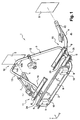
- Figure 1 is a perspective view of a load carrier according to an embodiment of the present invention in a fully assembled state ready for use;
- Figure 2 is a perspective view of the load carrier of Figure 1 with a support arch thereof in a partially disassembled state;
- Figure 3 is a perspective view of the load carrier of Figure 1 with a support arch thereof in a fully disassembled state and stowed in a storage position;
- Figure 4 is a plan view of the arrangement depicted in Figure 1;
- Figure 5 is a plan view of the arrangement depicted in Figure 2;
- Figure 6 is a plan view of the arrangement depicted in Figure 3;
- Figure 7 is a sectional view taken from the line A-A in Figure 4;
- Figure 8 is a sectional view taken from the line B-B in Figure 5;
- Figure 9 is a sectional view taken from the line C-C in Figure 6;
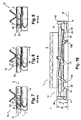
- Figure 10 is a rear view of the arrangement depicted in Figures 3 and 6;
- Figure 11 is the view of Figure 4 in which coupling members of the load carrier are in the folded-out;
- Figure 12 is the view of Figure 11 in which the coupling members have been pivoted into a folded-in position suitable for storage of the load carrier;
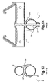
- Figure 13 is a sectional view taken from the line D-D in Figure 11;
- Figure 14 is a sectional view taken from the line E-E in Figure 12;
- Figure 15 is a perspective view of the load carrier of the previous figures shown with its supporting frame collapsed and its coupling members in the folded-in position, this view showing the load carrier in a fully collapsed state suitable for storage; and
- Figure 16 is a perspective view of part of Figure 1 and showing a modified arch coupling.
- Referring to the figures, and in particular for the moment to Figures 1 and 4, a load carrier 1 according to an exemplary and non-limiting embodiment of the present invention is illustrated in a fully assembled state. The load carrier 1 comprises a
loading frame 2, a supportingarch 3 and connectingmembers 4. Each of theseparts members 4 to avehicle 5, preferably to its rear, whichvehicle 5 is represented in the figure only by tworectangles 5. For connection to the vehicle, the connectingmembers 4 are provided at their vehicle-connection end with a manually operatedcoupling mechanism 40, each of which is configured to co-operate with an associatedmounting point 5 of the vehicle. - Fitted to, or integrated with, the
loading frame 2 are cargo members forming acargo loading area 11. One example of the sort of cargo members envisaged are channels or rails 6 on which the bicycles transported (not shown in the figures) can be loaded. It will be appreciated that theloading frame 2 andloading area 11 may take other forms in variations to the present invention in dependence on the type of cargo/load to be carried. The spread plane of theloading area 11 is marked with the angular arrow U and the direction of the assembled supporting arch 3 with the arrow T. The load carrier 1 may be regarded in the drawings as ready for fitting to the rear of a vehicle and for convenience is provided in plan view with an indication of what will therefore be facing the right "R" and left "L" sides of that vehicle. - The supporting
arch 3 when assembled into its in-use position extends substantially upwardly from the loading frame and substantially transversely relative to its spread plane U, for illustration of which reference may be made in particular to Figure 1. - The supporting arch 3 carries distancing arms/
load support arms 7, which in use are intended to be coupled to loaded bicycles to hold these in an upright position in association with the or eachrail 6. In other versions, theseload support arms 7 may be embodied in other forms in dependence on the type of cargo/load to be carried, e.g. they may comprise ski-racks, clips or similar load restraining members. At their arch-connecting end, thearms 7 in the present embodiment comprise a clamping ring that can be loosened and displaced around thearch 3 so as to vary the position of the support provided to the load. At their load supporting end, thearms 7 include a load attachment member, embodied for the present bicycle-carrying embodiment in the form of a pair of jaws hinged to close around a bicycle frame member and clamped on by a manually turned knob. Onearm 7 is provided by way of example perrail 6 or row of rails and the distance it extends away from thearch 3 depends on the position of therail 6 with which it is associated. - For the rear mounted embodiment under consideration, a plate is fitted to the
loading frame 2 in the form of alighting board 8, to whichlamps 9 are fitted and on which there is space for a number plate (not shown in the figure). This mimics the rear lamps of thevehicle 5 and improves safety for following road users. Thelighting board 8 is connected to theloading frame 2 withrotary couplings 10, by which thelighting board 8 can be folded down against theloading frame 2 to help in keeping the collapsed package size down, e.g. for storage of the load carrier 1. - The supporting
arch 3 may be a substantially inverted "U" in shape and comprises a first supportingarch part 12 and a second supportingarch part 13. Thesearch parts arch 3 is in at least its in-use position. Thearch parts arch 3 can be divided into its separatemain parts arch 3 for space-efficient storage or stowage of the load carrier 1. - The
arch parts arch 3 by a preferably manually operable coupling. In the present embodiment, this coupling is in the form of a screw joint 14 in which onearch part 13 includes amale fastener 14A that is adapted to screw into an alignedfemale fastener 14B so as the hold the twoarch parts arch 3. - The
arch parts actual locking mechanism 14 whosecomponent parts arch parts arch parts whole arch 3 and there is no need for additional components such as for example a crossbar. The direct interlocking between thearch parts arch parts - Referring for the moment to Figure 16 and in a modification to the embodiment illustrated in Figure 1, the
female part 14B may screw over the top of themale part 14A. In this version, use of a large diameter hand grip on the outside of thefemale part 14A may prove useful for increasing the mechanical advantage and therefore torque available when trying to undo a particularly tightly done up coupling. Some users may also find it preferable to use a large hand grip. Furthermore, in this arrangement if thefemale part 14B envelops themale part 14A protection of a thread or equivalent against the elements and contamination may be improved, e.g. against frost damage. This variation may be applied to any version of the present invention and in particular to the specific but non-limiting embodiment disclosed herein and with reference to the other figures. - It will be appreciated that other forms of coupling may be used such as a releasable snap-fit coupling, e.g. releasable bayonet joint. In whatever form the
coupling 14 is embodied, for user convenience it may prove advantageous to design thecoupling 14 such that it is adapted to be connectable and divisible without normally needing the aid of tools, neither of a special nor general variety. Thecoupling 14 is preferably disposed in a substantially central upper region of the arch 3 so as to keep the length of the arch parts approximately the same, which may prove aesthetically more pleasing to users than widely different lengths ofarch part - The supporting
arch parts loading frame 2 with a joint comprising a respective sleeve-shaft/tube arrangement 15. When thearch 3 has been divided into itsconstituent parts parts loading frame 2. A first stage in this operation can be seen by referring in particular to Figures 2 and 5, in which thearch 3 has been divided by unscrewing thecoupling 14. The first and secondarch parts arch parts loading frame 2 and may lie to the rear thereof, i.e. on the vehicle-facing side of the load carrier. Both thearch parts undivided arch 3. - Referring now also to Figures 4 to 6, it can be noted that the supporting
arch parts arch parts loading frame 2. Such a simple arrangement would call for a user to pull or push theframe parts arch parts arch parts - In Figure 4 the parts are in a coupled-together position and in Figure 5 the parts have been detached from each other and partially folded down. In different embodiments, only one or both
arch parts loading frame 2 to provide the necessary clearance. In the present embodiment, botharch parts arch part 12 towards theloading frame 2 and the otherarch part 13 away from theloading frame 2. Thus, as can be seen from Figure 5, one supportingarch part 12 has moved in the lateral direction relative to the other supportingarch part 13 in the direction marked by the arrow B, whilst theother part 13 has moved relative to the supportingarch part 12 in the direction marked by the arrow F. - In Figure 6 the supporting
arch parts arch parts arch parts arch parts arch 3. One advantage of displacing botharch parts arch part arch part arch 3. - Figure 10 shows the load carrier 1 viewed from the side intended to be connected to the
vehicle 5, which may for convenience be referred to as a rear view of the load carrier 1 in its collapsed state. The bottom plane of the load carrier 1 is marked by theline 16 and the supportingarch parts lighting board 8 is still in its non-folded-down position and the height of theloading area 11 above the bottom plane is marked by "h" and the height of the supportingarch parts loading area 11 and the pivoted downarch parts - Sectional views taken from the lines A-A, B-B and C-C in Figures 4, 5 and 6 may be seen by particular reference to Figures 7 to 9. In these figures, the shaft-
sleeve arrangement 15, by which the supportingarch part 12 is coupled to theloading frame 2 is shown in detail, along with an exemplary and preferred arrangement by which the or eacharch part - The broad idea of displacing the first and second arch parts (12, 13) away from each other may be achieved for example by use of a cam or groove and an associated follower. The specific but non-limiting embodiment is directed to the illustrated
arrangement 15 which is used to couple thepart 12, but it will be appreciated that the description is also applicable mutatis mutandis for the arrangement used to couple thepart 13 to theloading frame 2. The difference between the arrangements for thearch parts loading frame 2 and the other should automatically and preferably substantially simultaneously move outwards away from theloading frame 2. This minimises the actual movement in and/or out of each part and should make for greater user comfort and component durability. - A
sleeve 17 is used in the embodiment illustrated, which may constitute an integrated part of theloading frame 2 and may be an open end of a tubular member used in the construction of thatloading frame 2 itself. Thesleeve 17 could also be a separate part that is fastened to the load carrier 1. In thesleeve 17, ashaft 18 is introduced that constitutes an end part of the supportingarch part 12. Theshaft part 18 can be rotated in thesleeve 17 and theshaft part 18 and thesleeve 17 thus have a common fulcrum and common longitudinal axis, which is marked by the dash-dot line G-G in Figure 7. - The
shaft part 18, which may be tubular, defines therethrough one or more grooves 19 (two illustrated) whose longitudinal lines of action have been marked by the dashed line H-H. The line H-H has an inclination α to the line G-G. Fitted to thesleeve 18 are one ormore pins 20, one each of which extends into and interacts with eachgrooves 19. While the embodiment illustrated shows twopins 20 andgrooves 19 perarch part 12, it will be appreciated that one ormore pins 20 andcorresponding grooves 19 may be used or an equivalent thereto. - In Figure 7 the supporting
arch part 12 is in its raised position and coupled together with the otherarch part 13 to form theclosed arch 3 and thepins 20 are disposed in afirst end position 21 of theirgrooves 19. In Figure 8 thearch part 12 has been partially pivoted down and theshaft 18 has been rotated in thesleeve 17. Thegroove 19 and thepin 20 have therefore interacted such that theshaft 18 has been partially and automatically moved further into thesleeve 17 in the direction shown by the arrow B. In Figure 9, thearch part 12 has been pivoted fully down and theshaft 18 has moved further in the direction of the arrow B. In the position shown in Figure 9, further rotation of theshaft 18 is blocked by the fact that theother end 22 of thegrooves 19 comes into contact with thepins 20. - The pivotal mounting of the connecting
members 4 directly to theloading frame 2 will now be described, with reference in particular to Figures 11 to 14. The connectingmembers 4 may each comprise an arm including apipe part 23, which is connected to theloading frame 2 by means of a screw joint 24. The screw joint 24 serves as a rotation shaft for the connectingmember 4, so that it can fold inwards to a stowage position. - For mounting the load carrier 1 onto the vehicle, the connecting
members 4 are moved into an in-use position in which they project outwards away from theloading frame 2 and towards the vehicle. The connectingmembers 4 are illustrated captured in this position in for example each of figures 1 to 6. The pivotal connection provided by the screw joint allows the connectingmembers 4 to be pivoted between this in-use position and a stowage position that is in the region of theloading frame 2, i.e. near to it which can include positions next to or alongside it. The connectingmembers 4 are, however, preferably stowed underneath theloading frame 2. There, they do not interfere with the storage position of thecollapsed arch loading frame 2, for which see for example figure 10. In addition, under-slung mounting of the connectingmembers 4 ensures that the weight of the load bears downwards onto the connectingmembers 4 and thepivotal connection 24 takes none of the carrier load in tension. - Fitted to the
pipe part 23 on each side of the screw joint 24 is an clip in the form of aninterlay 25. Theinterlay 25 is connected byscrews 26, rivets or similar to thepipe part 23 and the interlay is shaped on theside 27 facing theloading frame 2 such that it fits tightly against theloading frame 2 when the connectingmember 4 is in the folded-out position, which position is shown in Figure 11. Theinterlay 25 is preferably made of a resilient material, which allows the connectingmember 4 to be pivotable between the folded-out position shown in Figure 11 and the folded-in position shown in Figure 12. The tight fitting of theinterlay 25 against theloading frame 2 has the effect that the connectingmembers 4, when in the folded-out position, are captured in position and are not inadvertently shifted out of this position, which makes the load carrier 1 easier to fit to thevehicle 5. - The connecting
members 4 are preferably configured for stowage in an at least partially over-lapping relationship, which helps with compactness. The connectingmembers 4 are mounted separately by independentpivotal connections 24 and this enables them to be folded inwardly one by one to achieve the compact stowage illustrated with ease of use for the operator. It is also of note that once the connecting members are in their stowed positions, the vehicle connection end of neither projects outwards of theloading frame 2. This keeps everything compact and reduces chances of tripping the user. - The pivotal mounting 24 of the connecting
members 4 is made onto opposing side members of the loading frame and is asymmetric, e.g. the right handside mounting member 4 is mounted further back than the left hand one. This helps offset the connectingmembers 4 and can be useful in setting up over-lapping stowage positions, in particular when combined with asymmetric offsets to the arms forming the connecting members. The asymmetry of the connectingmembers 4 and their step outwards allows them to achieve a good width in the in-use position but aids compact stowage. Mounting the connectingmembers 4 directly onto theloading frame 2 keeps down component count, weight and cost. - When the load carrier 1 is uncoupled from the
vehicle 5 to which it has been connected, the load carrier 1 is in the position which can be seen from Figures 1 and 4. In this position, the screw joint 14 is released and the supportingarch parts arch parts arch parts arch 3 can be seen with particular reference to Figures 3 and 6. - The connecting
members 4 are next folded inwards towards the middle of and beneath theloading frame 2, whereafter thelighting board 8 is rotated about its pivot edge to make bearing contact against theloading frame 2, thereby producing a fully collapsed and very compact load carrier 1 of the appearance represented in Figure 15, which load carrier 1 requires little storage space. It may be noted that thedistance arms 7 lie substantially across theloading area 11 and may be down against thetracks 6 when the load carrier is in its fully collapsed state or may lie substantially between them (e.g. as illustrated in Fig. 6). In particular, the load carrier 1 in its collapsed/storage condition does not suffer from the disadvantage felt by some prior art load carriers because the manner in which itsarch 3 is divided enables its collapse into a position H in which no part of thearch 3 juts out over the back of theloading area 11. This co-operates with the similarly efficient stowage of the connectingmembers 4 under theloading area 11 so as to produce a very compact package for storage or transport when the load carrier 1 is not being used to carry a load. - The load carrier 1 of this or other embodiments may be supplied in the form of an original equipment part fitted to, or supplied in relation with, a new or used
vehicle 5. It could also be supplied as a dealer-fit optional extra with a new vehicle or could be sold as an after-market accessory supplied as an item for hire. In one version, the load carrier 1 could be supplied in the form of a kit of parts. Such a kit of parts would preferably have included therein at least substantially all the components for assembly of a load carrier 1 according to an embodiment of the present invention.
Claims (17)
- A load carrier for coupling to a vehicle (5), said load carrier (1) comprising a loading frame (2) and first and second longitudinally extending connecting members (4) for coupling said load carrier to said vehicle (5), said connecting members being pivotally mounted onto said loading frame (2) and being configured to be pivoted between an outwardly projecting in-use position for connection to said vehicle, and a folded-in stowage position in the region of said loading frame (2), characterised in that the mounting of said first and said second connecting members (4) to said loading frame (2) is asymmetric between the respective pivotal connections (24) thereto of said connecting members.
- A load carrier according to claim 1, wherein said connecting members (4) are separately mounted onto said loading frame (2) by means of independent pivotal connections (24).
- A load carrier according to claim 1 or claim 2, wherein said connecting members (4) are configured for stowage in an at least partially overlapping relationship.
- A load carrier according to any preceding claim, wherein a vehicle-connection end of each said connecting member (4) is configured to pivot from its in-use position in towards the middle of said loading frame (2) so as to reach its respective stowage position.
- A load carrier according to any preceding claim, wherein said connecting members (4) are pivotally mounted directly onto said loading frame (2).
- A load carrier according to any preceding claim, wherein said connecting members (4) are pivotally mounted onto opposing side members of said loading frame (2).
- A load carrier according to any preceding claim, wherein said connecting members (4) are pivotally mounted onto the underside of said loading frame (2).
- A load carrier according to any preceding claim, wherein said stowage position is underneath said loading frame (2).
- A load carrier according to any preceding claim wherein, when a said connecting member (4) is in its stowage position, a vehicle-connection end of said connecting member does not protrude outside the perimeter of said loading frame (2).
- A load carrier according to any preceding claim, wherein each said pivotal connection (24) comprises a screw joint configured to operate as a rotation shaft for its associated said connecting member (4).
- A load carrier according to any preceding claim, wherein each said connecting member (4) further comprises a clip (25) that is attached thereto and configured to capture its associated said connecting member against said loading frame (2) when said connecting member is in its in-use position.
- A load carrier according to claim 11, wherein said loading frame (2) and each said connecting member (4) are of tubular construction in the region of said clip (25) and wherein said clip comprises an interlay configured to capture its associated connecting member against said loading frame when said connecting member is in its in-use position.
- A load carrier according to any preceding claim, wherein said connecting members (4) are configured for connection of said load carrier to the rear of said vehicle (5).
- A load carrier according to any preceding claim, further comprising a supporting arch (3) that extends substantially upwardly (T) from and transversely to said loading frame (2), said supporting arch being divisible into first and second arch parts (12, 13), each of which arch parts is pivotally coupled (15) to said loading frame such that, when divided, each of said first and second arch parts is configured to be pivoted down to a storage position lying substantially level with said loading frame.
- A load carrier according to claim 14, wherein the storage position of the first and second arch parts (12, 13) is on top of said loading frame (2).
- A load carrier according to any preceding claim, wherein said load carrier (1) comprises a bicycle carrier.
- A kit of parts adapted to be assembled into a load carrier (1) according to any preceding claim.
Priority Applications (1)
| Application Number | Priority Date | Filing Date | Title |
|---|---|---|---|
| EP04740853A EP1648740B1 (en) | 2003-07-11 | 2004-07-06 | Load carriers for vehicles |
Applications Claiming Priority (5)
| Application Number | Priority Date | Filing Date | Title |
|---|---|---|---|
| EP03291731 | 2003-07-11 | ||
| EP04290509 | 2004-02-25 | ||
| EP04290510 | 2004-02-25 | ||
| EP04740853A EP1648740B1 (en) | 2003-07-11 | 2004-07-06 | Load carriers for vehicles |
| PCT/EP2004/007572 WO2005005205A1 (en) | 2003-07-11 | 2004-07-06 | Load carriers for vehicles |
Publications (2)
| Publication Number | Publication Date |
|---|---|
| EP1648740A1 EP1648740A1 (en) | 2006-04-26 |
| EP1648740B1 true EP1648740B1 (en) | 2007-01-03 |
Family
ID=34068729
Family Applications (2)
| Application Number | Title | Priority Date | Filing Date |
|---|---|---|---|
| EP04740853A Expired - Lifetime EP1648740B1 (en) | 2003-07-11 | 2004-07-06 | Load carriers for vehicles |
| EP04740852A Expired - Lifetime EP1646531B1 (en) | 2003-07-11 | 2004-07-06 | Load carriers for vehicles |
Family Applications After (1)
| Application Number | Title | Priority Date | Filing Date |
|---|---|---|---|
| EP04740852A Expired - Lifetime EP1646531B1 (en) | 2003-07-11 | 2004-07-06 | Load carriers for vehicles |
Country Status (5)
| Country | Link |
|---|---|
| US (1) | US8047412B2 (en) |
| EP (2) | EP1648740B1 (en) |
| AT (2) | ATE370030T1 (en) |
| DE (2) | DE602004004141T2 (en) |
| WO (2) | WO2005005205A1 (en) |
Families Citing this family (13)
| Publication number | Priority date | Publication date | Assignee | Title |
|---|---|---|---|---|
| US8109422B2 (en) * | 2005-08-10 | 2012-02-07 | Thule Sweden Ab | Collapsible rear mounted load carrier for a vehicle |
| DE102008051423B3 (en) * | 2008-10-11 | 2010-05-12 | Klaus Uebler | Tail carrier, particularly bicycle carrier for attachment within tail range of vehicle, particularly at trailer coupling or at rear flap of vehicle, has forked carrier framework in U-shape or V-shape with two holding arms |
| DE102009060366B4 (en) | 2009-12-24 | 2021-07-08 | Volkswagen Ag | Load carrier |
| DE102010024852B4 (en) * | 2010-06-24 | 2023-08-31 | Volkswagen Ag | Arrangement for fastening a load carrier to the rear of a vehicle and load carrier thereto |
| DE102012010049B4 (en) * | 2012-05-22 | 2015-11-26 | Springer Gmbh | Double-sided swivel arm for a workpiece holding element, in particular a workpiece gripper, in particular for holding and / or transporting body parts in the vehicle body shell |
| USD753577S1 (en) * | 2014-08-05 | 2016-04-12 | David James Duncan | Bicycle carrier |
| DE102015001804A1 (en) * | 2015-02-11 | 2016-08-11 | GM Global Technology Operations LLC (n. d. Ges. d. Staates Delaware) | Load carrier for arrangement at the rear of a motor vehicle |
| KR101673792B1 (en) | 2015-07-14 | 2016-11-08 | 현대자동차주식회사 | Bicycle carrier apparatus for vehicle |
| US10703295B2 (en) * | 2016-10-20 | 2020-07-07 | Ford Global Technologies, Llc | Pickup truck having cargo bed with elevated bicycle rack |
| US10513227B2 (en) | 2016-10-20 | 2019-12-24 | Ford Global Technologies, Llc | Pickup truck having cargo bed with side mounted bicycle rack |
| USD877685S1 (en) * | 2018-09-13 | 2020-03-10 | Thule Sweden Ab | Carrier |
| DE202019102923U1 (en) * | 2019-05-23 | 2020-08-25 | Ga Actuation Systems Gmbh | Clamping device for bars |
| BE1031477B1 (en) * | 2023-03-30 | 2024-10-31 | Prostor | Bicycle carrier |
Family Cites Families (6)
| Publication number | Priority date | Publication date | Assignee | Title |
|---|---|---|---|---|
| US3670935A (en) | 1970-11-09 | 1972-06-20 | Paul R Hinkston | Collapsible cycle carrier |
| DE29605554U1 (en) | 1996-03-26 | 1996-05-30 | Bahre, Michael, 33647 Bielefeld | Rear luggage rack for motor vehicles |
| US5794828A (en) * | 1996-08-12 | 1998-08-18 | Colan; Peter V. | Racking system for transporting a bicycle |
| SE512862C2 (en) | 1996-09-09 | 2000-05-22 | Thule Ind Ab | Cargo carrier for mounting on the back of a vehicle |
| DE1095820T1 (en) * | 1999-10-25 | 2001-10-11 | Industri Ab Thule, Hillerstorp | charge carrier |
| US20020117524A1 (en) | 2001-02-28 | 2002-08-29 | Chanyoung Jeong | Trunk mountable equipment rack |
-
2004
- 2004-07-06 EP EP04740853A patent/EP1648740B1/en not_active Expired - Lifetime
- 2004-07-06 DE DE602004004141T patent/DE602004004141T2/en not_active Expired - Lifetime
- 2004-07-06 AT AT04740852T patent/ATE370030T1/en not_active IP Right Cessation
- 2004-07-06 EP EP04740852A patent/EP1646531B1/en not_active Expired - Lifetime
- 2004-07-06 AT AT04740853T patent/ATE350242T1/en not_active IP Right Cessation
- 2004-07-06 WO PCT/EP2004/007572 patent/WO2005005205A1/en not_active Ceased
- 2004-07-06 WO PCT/EP2004/007571 patent/WO2005005204A1/en not_active Ceased
- 2004-07-06 DE DE602004008290T patent/DE602004008290T2/en not_active Expired - Lifetime
- 2004-07-06 US US10/567,449 patent/US8047412B2/en not_active Expired - Fee Related
Also Published As
| Publication number | Publication date |
|---|---|
| WO2005005204A1 (en) | 2005-01-20 |
| DE602004004141D1 (en) | 2007-02-15 |
| EP1646531B1 (en) | 2007-08-15 |
| EP1646531A1 (en) | 2006-04-19 |
| ATE370030T1 (en) | 2007-09-15 |
| DE602004008290T2 (en) | 2008-05-08 |
| ATE350242T1 (en) | 2007-01-15 |
| US20080203750A1 (en) | 2008-08-28 |
| WO2005005205A1 (en) | 2005-01-20 |
| US8047412B2 (en) | 2011-11-01 |
| EP1648740A1 (en) | 2006-04-26 |
| DE602004004141T2 (en) | 2007-10-11 |
| DE602004008290D1 (en) | 2007-09-27 |
Similar Documents
| Publication | Publication Date | Title |
|---|---|---|
| EP1646531B1 (en) | Load carriers for vehicles | |
| EP3756956B1 (en) | Rack assembly | |
| US5765855A (en) | Foldable stroller | |
| US5979856A (en) | Music stand | |
| JP2791184B2 (en) | Luggage carrier that can be folded freely | |
| JP3759730B2 (en) | folding bicycle | |
| EP0119252B1 (en) | A foldable chair frame | |
| US4606575A (en) | Lock release for folding table | |
| US7052081B2 (en) | Foldable chair | |
| US6979013B2 (en) | Bicycle foldable to align front and rear wheels along a transverse direction of the bicycle | |
| US6752090B2 (en) | Folding desk | |
| EP0994004B1 (en) | Fold latch assembly for a stroller | |
| US20030024445A1 (en) | Folding table | |
| US6959938B1 (en) | Folding collapsible baby trailer | |
| CN102317138B (en) | Stroller | |
| US20060249331A1 (en) | Foldable step ladder with leg aligner and handle | |
| US4022485A (en) | Collapsible bicycle | |
| US8070028B2 (en) | Foldable truck bed extender | |
| US12220058B2 (en) | Sofa bed | |
| CN109415019A (en) | Cargo carrying frame component with linkage | |
| US20020154942A1 (en) | Apparatus for pop-up display structures | |
| US5626351A (en) | Collapsible hand cart | |
| GB2275028A (en) | Telescopic and folding frame assembly for a golf cart | |
| CN100445130C (en) | Load carrier for vehicle | |
| CN223100804U (en) | A detachable snap-on connector and a child carrier |
Legal Events
| Date | Code | Title | Description |
|---|---|---|---|
| PUAI | Public reference made under article 153(3) epc to a published international application that has entered the european phase |
Free format text: ORIGINAL CODE: 0009012 |
|
| 17P | Request for examination filed |
Effective date: 20060213 |
|
| AK | Designated contracting states |
Kind code of ref document: A1 Designated state(s): AT BE BG CH CY CZ DE DK EE ES FI FR GB GR HU IE IT LI LU MC NL PL PT RO SE SI SK TR |
|
| GRAP | Despatch of communication of intention to grant a patent |
Free format text: ORIGINAL CODE: EPIDOSNIGR1 |
|
| DAX | Request for extension of the european patent (deleted) | ||
| GRAS | Grant fee paid |
Free format text: ORIGINAL CODE: EPIDOSNIGR3 |
|
| GRAA | (expected) grant |
Free format text: ORIGINAL CODE: 0009210 |
|
| AK | Designated contracting states |
Kind code of ref document: B1 Designated state(s): AT BE BG CH CY CZ DE DK EE ES FI FR GB GR HU IE IT LI LU MC NL PL PT RO SE SI SK TR |
|
| PG25 | Lapsed in a contracting state [announced via postgrant information from national office to epo] |
Ref country code: SI Free format text: LAPSE BECAUSE OF FAILURE TO SUBMIT A TRANSLATION OF THE DESCRIPTION OR TO PAY THE FEE WITHIN THE PRESCRIBED TIME-LIMIT Effective date: 20070103 Ref country code: PL Free format text: LAPSE BECAUSE OF FAILURE TO SUBMIT A TRANSLATION OF THE DESCRIPTION OR TO PAY THE FEE WITHIN THE PRESCRIBED TIME-LIMIT Effective date: 20070103 Ref country code: FI Free format text: LAPSE BECAUSE OF FAILURE TO SUBMIT A TRANSLATION OF THE DESCRIPTION OR TO PAY THE FEE WITHIN THE PRESCRIBED TIME-LIMIT Effective date: 20070103 Ref country code: AT Free format text: LAPSE BECAUSE OF FAILURE TO SUBMIT A TRANSLATION OF THE DESCRIPTION OR TO PAY THE FEE WITHIN THE PRESCRIBED TIME-LIMIT Effective date: 20070103 Ref country code: NL Free format text: LAPSE BECAUSE OF FAILURE TO SUBMIT A TRANSLATION OF THE DESCRIPTION OR TO PAY THE FEE WITHIN THE PRESCRIBED TIME-LIMIT Effective date: 20070103 Ref country code: CH Free format text: LAPSE BECAUSE OF FAILURE TO SUBMIT A TRANSLATION OF THE DESCRIPTION OR TO PAY THE FEE WITHIN THE PRESCRIBED TIME-LIMIT Effective date: 20070103 Ref country code: LI Free format text: LAPSE BECAUSE OF FAILURE TO SUBMIT A TRANSLATION OF THE DESCRIPTION OR TO PAY THE FEE WITHIN THE PRESCRIBED TIME-LIMIT Effective date: 20070103 Ref country code: DK Free format text: LAPSE BECAUSE OF FAILURE TO SUBMIT A TRANSLATION OF THE DESCRIPTION OR TO PAY THE FEE WITHIN THE PRESCRIBED TIME-LIMIT Effective date: 20070103 |
|
| REG | Reference to a national code |
Ref country code: GB Ref legal event code: FG4D |
|
| REF | Corresponds to: |
Ref document number: 602004004141 Country of ref document: DE Date of ref document: 20070215 Kind code of ref document: P |
|
| REG | Reference to a national code |
Ref country code: IE Ref legal event code: FG4D |
|
| PG25 | Lapsed in a contracting state [announced via postgrant information from national office to epo] |
Ref country code: SE Free format text: LAPSE BECAUSE OF FAILURE TO SUBMIT A TRANSLATION OF THE DESCRIPTION OR TO PAY THE FEE WITHIN THE PRESCRIBED TIME-LIMIT Effective date: 20070403 Ref country code: BG Free format text: LAPSE BECAUSE OF FAILURE TO SUBMIT A TRANSLATION OF THE DESCRIPTION OR TO PAY THE FEE WITHIN THE PRESCRIBED TIME-LIMIT Effective date: 20070403 |
|
| PG25 | Lapsed in a contracting state [announced via postgrant information from national office to epo] |
Ref country code: ES Free format text: LAPSE BECAUSE OF FAILURE TO SUBMIT A TRANSLATION OF THE DESCRIPTION OR TO PAY THE FEE WITHIN THE PRESCRIBED TIME-LIMIT Effective date: 20070414 |
|
| PG25 | Lapsed in a contracting state [announced via postgrant information from national office to epo] |
Ref country code: PT Free format text: LAPSE BECAUSE OF FAILURE TO SUBMIT A TRANSLATION OF THE DESCRIPTION OR TO PAY THE FEE WITHIN THE PRESCRIBED TIME-LIMIT Effective date: 20070604 |
|
| NLV1 | Nl: lapsed or annulled due to failure to fulfill the requirements of art. 29p and 29m of the patents act | ||
| REG | Reference to a national code |
Ref country code: CH Ref legal event code: PL |
|
| ET | Fr: translation filed | ||
| PLBE | No opposition filed within time limit |
Free format text: ORIGINAL CODE: 0009261 |
|
| STAA | Information on the status of an ep patent application or granted ep patent |
Free format text: STATUS: NO OPPOSITION FILED WITHIN TIME LIMIT |
|
| PG25 | Lapsed in a contracting state [announced via postgrant information from national office to epo] |
Ref country code: SK Free format text: LAPSE BECAUSE OF FAILURE TO SUBMIT A TRANSLATION OF THE DESCRIPTION OR TO PAY THE FEE WITHIN THE PRESCRIBED TIME-LIMIT Effective date: 20070103 |
|
| 26N | No opposition filed |
Effective date: 20071005 |
|
| PG25 | Lapsed in a contracting state [announced via postgrant information from national office to epo] |
Ref country code: RO Free format text: LAPSE BECAUSE OF FAILURE TO SUBMIT A TRANSLATION OF THE DESCRIPTION OR TO PAY THE FEE WITHIN THE PRESCRIBED TIME-LIMIT Effective date: 20070103 Ref country code: CZ Free format text: LAPSE BECAUSE OF FAILURE TO SUBMIT A TRANSLATION OF THE DESCRIPTION OR TO PAY THE FEE WITHIN THE PRESCRIBED TIME-LIMIT Effective date: 20070103 |
|
| PG25 | Lapsed in a contracting state [announced via postgrant information from national office to epo] |
Ref country code: MC Free format text: LAPSE BECAUSE OF NON-PAYMENT OF DUE FEES Effective date: 20070731 Ref country code: GR Free format text: LAPSE BECAUSE OF FAILURE TO SUBMIT A TRANSLATION OF THE DESCRIPTION OR TO PAY THE FEE WITHIN THE PRESCRIBED TIME-LIMIT Effective date: 20070404 |
|
| PG25 | Lapsed in a contracting state [announced via postgrant information from national office to epo] |
Ref country code: IE Free format text: LAPSE BECAUSE OF NON-PAYMENT OF DUE FEES Effective date: 20070706 |
|
| PG25 | Lapsed in a contracting state [announced via postgrant information from national office to epo] |
Ref country code: EE Free format text: LAPSE BECAUSE OF FAILURE TO SUBMIT A TRANSLATION OF THE DESCRIPTION OR TO PAY THE FEE WITHIN THE PRESCRIBED TIME-LIMIT Effective date: 20070103 |
|
| PG25 | Lapsed in a contracting state [announced via postgrant information from national office to epo] |
Ref country code: CY Free format text: LAPSE BECAUSE OF FAILURE TO SUBMIT A TRANSLATION OF THE DESCRIPTION OR TO PAY THE FEE WITHIN THE PRESCRIBED TIME-LIMIT Effective date: 20070103 |
|
| PG25 | Lapsed in a contracting state [announced via postgrant information from national office to epo] |
Ref country code: LU Free format text: LAPSE BECAUSE OF NON-PAYMENT OF DUE FEES Effective date: 20070706 |
|
| PG25 | Lapsed in a contracting state [announced via postgrant information from national office to epo] |
Ref country code: TR Free format text: LAPSE BECAUSE OF FAILURE TO SUBMIT A TRANSLATION OF THE DESCRIPTION OR TO PAY THE FEE WITHIN THE PRESCRIBED TIME-LIMIT Effective date: 20070103 Ref country code: HU Free format text: LAPSE BECAUSE OF FAILURE TO SUBMIT A TRANSLATION OF THE DESCRIPTION OR TO PAY THE FEE WITHIN THE PRESCRIBED TIME-LIMIT Effective date: 20070704 |
|
| PGFP | Annual fee paid to national office [announced via postgrant information from national office to epo] |
Ref country code: IT Payment date: 20120613 Year of fee payment: 9 |
|
| PGFP | Annual fee paid to national office [announced via postgrant information from national office to epo] |
Ref country code: GB Payment date: 20120704 Year of fee payment: 9 |
|
| PGFP | Annual fee paid to national office [announced via postgrant information from national office to epo] |
Ref country code: BE Payment date: 20120713 Year of fee payment: 9 |
|
| BERE | Be: lapsed |
Owner name: RENAULT S.A.S. Effective date: 20130731 Owner name: THULE SWEDEN A.B. Effective date: 20130731 |
|
| GBPC | Gb: european patent ceased through non-payment of renewal fee |
Effective date: 20130706 |
|
| PG25 | Lapsed in a contracting state [announced via postgrant information from national office to epo] |
Ref country code: GB Free format text: LAPSE BECAUSE OF NON-PAYMENT OF DUE FEES Effective date: 20130706 Ref country code: BE Free format text: LAPSE BECAUSE OF NON-PAYMENT OF DUE FEES Effective date: 20130731 |
|
| PG25 | Lapsed in a contracting state [announced via postgrant information from national office to epo] |
Ref country code: IT Free format text: LAPSE BECAUSE OF NON-PAYMENT OF DUE FEES Effective date: 20130706 |
|
| REG | Reference to a national code |
Ref country code: FR Ref legal event code: PLFP Year of fee payment: 12 |
|
| REG | Reference to a national code |
Ref country code: FR Ref legal event code: PLFP Year of fee payment: 13 |
|
| PGFP | Annual fee paid to national office [announced via postgrant information from national office to epo] |
Ref country code: FR Payment date: 20160628 Year of fee payment: 13 |
|
| PGFP | Annual fee paid to national office [announced via postgrant information from national office to epo] |
Ref country code: DE Payment date: 20160628 Year of fee payment: 13 |
|
| REG | Reference to a national code |
Ref country code: DE Ref legal event code: R119 Ref document number: 602004004141 Country of ref document: DE |
|
| REG | Reference to a national code |
Ref country code: FR Ref legal event code: ST Effective date: 20180330 |
|
| PG25 | Lapsed in a contracting state [announced via postgrant information from national office to epo] |
Ref country code: DE Free format text: LAPSE BECAUSE OF NON-PAYMENT OF DUE FEES Effective date: 20180201 |
|
| PG25 | Lapsed in a contracting state [announced via postgrant information from national office to epo] |
Ref country code: FR Free format text: LAPSE BECAUSE OF NON-PAYMENT OF DUE FEES Effective date: 20170731 |