EP1648273B1 - Juicer - Google Patents
Juicer Download PDFInfo
- Publication number
- EP1648273B1 EP1648273B1 EP04737452A EP04737452A EP1648273B1 EP 1648273 B1 EP1648273 B1 EP 1648273B1 EP 04737452 A EP04737452 A EP 04737452A EP 04737452 A EP04737452 A EP 04737452A EP 1648273 B1 EP1648273 B1 EP 1648273B1
- Authority
- EP
- European Patent Office
- Prior art keywords
- cap
- lid
- feed tube
- gap
- rim
- Prior art date
- Legal status (The legal status is an assumption and is not a legal conclusion. Google has not performed a legal analysis and makes no representation as to the accuracy of the status listed.)
- Expired - Lifetime
Links
- 235000011389 fruit/vegetable juice Nutrition 0.000 claims abstract description 35
- 239000002184 metal Substances 0.000 claims abstract description 7
- 238000007789 sealing Methods 0.000 claims description 2
- 229910001220 stainless steel Inorganic materials 0.000 abstract description 5
- 239000010935 stainless steel Substances 0.000 abstract description 5
- 229910000831 Steel Inorganic materials 0.000 abstract description 3
- 239000004417 polycarbonate Substances 0.000 abstract description 3
- 229920000515 polycarbonate Polymers 0.000 abstract description 3
- 239000010959 steel Substances 0.000 abstract description 3
- 239000003550 marker Substances 0.000 description 4
- 239000000463 material Substances 0.000 description 3
- 239000002699 waste material Substances 0.000 description 3
- 239000012530 fluid Substances 0.000 description 2
- 239000006260 foam Substances 0.000 description 2
- 235000012055 fruits and vegetables Nutrition 0.000 description 2
- 238000007373 indentation Methods 0.000 description 2
- 239000007788 liquid Substances 0.000 description 2
- 244000141359 Malus pumila Species 0.000 description 1
- 239000004677 Nylon Substances 0.000 description 1
- 235000021016 apples Nutrition 0.000 description 1
- 238000005336 cracking Methods 0.000 description 1
- 235000013399 edible fruits Nutrition 0.000 description 1
- 230000037431 insertion Effects 0.000 description 1
- 238000003780 insertion Methods 0.000 description 1
- 229920001778 nylon Polymers 0.000 description 1
- 239000004033 plastic Substances 0.000 description 1
- 229920000642 polymer Polymers 0.000 description 1
- 230000008719 thickening Effects 0.000 description 1
- 210000001364 upper extremity Anatomy 0.000 description 1
- 230000000007 visual effect Effects 0.000 description 1
- 238000003466 welding Methods 0.000 description 1
Images







Classifications
-
- A—HUMAN NECESSITIES
- A47—FURNITURE; DOMESTIC ARTICLES OR APPLIANCES; COFFEE MILLS; SPICE MILLS; SUCTION CLEANERS IN GENERAL
- A47J—KITCHEN EQUIPMENT; COFFEE MILLS; SPICE MILLS; APPARATUS FOR MAKING BEVERAGES
- A47J43/00—Implements for preparing or holding food, not provided for in other groups of this subclass
- A47J43/25—Devices for grating
- A47J43/255—Devices for grating with grating discs or drums
-
- A—HUMAN NECESSITIES
- A47—FURNITURE; DOMESTIC ARTICLES OR APPLIANCES; COFFEE MILLS; SPICE MILLS; SUCTION CLEANERS IN GENERAL
- A47J—KITCHEN EQUIPMENT; COFFEE MILLS; SPICE MILLS; APPARATUS FOR MAKING BEVERAGES
- A47J19/00—Household machines for straining foodstuffs; Household implements for mashing or straining foodstuffs
- A47J19/02—Citrus fruit squeezers; Other fruit juice extracting devices
-
- A—HUMAN NECESSITIES
- A47—FURNITURE; DOMESTIC ARTICLES OR APPLIANCES; COFFEE MILLS; SPICE MILLS; SUCTION CLEANERS IN GENERAL
- A47J—KITCHEN EQUIPMENT; COFFEE MILLS; SPICE MILLS; APPARATUS FOR MAKING BEVERAGES
- A47J19/00—Household machines for straining foodstuffs; Household implements for mashing or straining foodstuffs
- A47J19/02—Citrus fruit squeezers; Other fruit juice extracting devices
- A47J19/027—Centrifugal extractors
-
- A—HUMAN NECESSITIES
- A47—FURNITURE; DOMESTIC ARTICLES OR APPLIANCES; COFFEE MILLS; SPICE MILLS; SUCTION CLEANERS IN GENERAL
- A47J—KITCHEN EQUIPMENT; COFFEE MILLS; SPICE MILLS; APPARATUS FOR MAKING BEVERAGES
- A47J43/00—Implements for preparing or holding food, not provided for in other groups of this subclass
- A47J43/04—Machines for domestic use not covered elsewhere, e.g. for grinding, mixing, stirring, kneading, emulsifying, whipping or beating foodstuffs, e.g. power-driven
- A47J43/07—Parts or details, e.g. mixing tools, whipping tools
- A47J43/0716—Parts or details, e.g. mixing tools, whipping tools for machines with tools driven from the lower side
Definitions
- This invention relates to electric juicing devices, and is concerned especially with electric juicing devices of the kind for fruit and vegetables.
- An electric juicing device of this kind is known from GB-A-852220 in which the lid of the device comprises a cap with an integrally-formed feed tube.
- lids of electric juicing devices are integrally moulded in this way of a polymeric material, the use of such material having the advantage that it can be readily moulded in a transparent form that allows the flow of the pulp to be viewed for the avoidance of blockages.
- a lid for an electric juicing device comprising a polymeric cap with a feed tube, characterised in that the cap is formed with an opening therein, and that the feed tube is a metal feed tube attached to the cap within the opening.
- a metal feed tube attached to a polymeric cap has the advantage that it allows adequate strength to be provided in the feed tube whilst at the same time allowing for viewing pulp-flow. More particularly where a knife is to be provided in the feed tube, this can be attached securely, for example by welding, into or onto the tube itself.
- the invention may find application in an electric juicing device as disclosed in claim 9.
- a juicer 10 comprises a housing 11 a lid 12 with feed tube 51, a pulp collector 13 and a collection jug 14, A motor within the housing spins a grating disk 20 located under the feed tube 51.
- the housing 11 further consists of a lower compartment 15 and an upper compartment or juice collector 16.
- the lower compartment 15 houses the juicer's motor, controls 17 and power supply.
- the lower compartment 15 further includes a lower rim 19 that is flared outward.
- the device's feet 18 are mounted under the flared rim 19. In preferred embodiments, the feet have rubber bottoms in which are formed indentations 18a, as will be explained.
- the upper compartment or juice collector 16 is a removable component preferably fabricated from stainless steel.
- the interior compartment or collection reservoir 16a of the juice collector 16 comprises a central opening 21 that is surrounded by an upturned rim 22.
- the collection reservoir of the juice collector 16 is defined by an exterior wall 23.
- the upper extremity of the interior compartment is defined by a horizontal rim 24 that surrounds a central opening 25. This rim 24 prevents juice from escaping from, and pulp from entering the reservoir 16a.
- Integral with the exterior wall 23 and horizontal rim 24 is a juice stopping rim 26 which is inclined slightly from the vertical and which terminates in the 'U' or "J" shaped rim 27.
- the juice-stopping ring 26 includes a pair of opposed indentations 30 for locating tabs protruding from the underside of the lid to orientate the lid with respect to the juice collector. It will be observed that the juice-stopping rim 26 does not completely surround the juice collector's sidewall 23. Instead, the juice-stopping ring 26 includes a gap 32. The sides of the gap 32 are defined by the tapered or rolled off portions of 33 of the juice-stopping ring 26 and thereby define a spout. This spout further comprises a down turned lip portion 34, which is shown in figure 3 and extends below the level of the horizontal rim 24.
- a gap 35 is formed between the lip 34 and the sidewall 23 that gap is able to accommodate a rim of the pulp collector 13 or a pulp disposal chute as will be further explained.
- the pulp collector 13 comprises a container with a generally 'D' shaped cross section that conforms to the exterior of the housing 11.
- the upper rim 40 of the pulp collector 13 includes an arcuate or concave portion adjacent (in use) to the housing 11.
- the concave portion 41 of the rim 40 closely conforms to the outer surface of the sidewall 23 and fits into the gap 35 defined by the descending lip 34 and the sidewall 23.
- the upper rim 40 also includes an enlargement 42 that forms a convenient grip.
- one entire side of the pulp collector 13 is concave so to conform to the exterior shape of the housing 11.
- a lower portion 43 of the collector 13, adjacent the housing 11 be indented so as to conform with the enlarged rim 19 of the housing 11.
- both the descending lip 34 of the spout 32 and the sidewall portions 33 extend below the level of the upper rim 40 of the collector 13.
- the top inside surface of the pulp collector 40 must closely fit the surfaces of the lid to prevent the leakage of air and fluids 52. This can make the pulp collector difficult to remove.
- the interior of the pulp collector 40 also has one or more vertical ribs 140 near it rim 40 as shown in Figures 2 and 3 . When the handle 42 of the pulp collector is lifted, this rib acts on the cap as fulcrum to prevent the pulp container from jamming up onto the lid and causing the lip 41 to pivot downward so that the collector is easily removed.
- the lid 12 of the device provides several important functions. It prevents juice from escaping, it diverts pulp efficiently toward the collector 13 or chute 150 ( Figure 11 ), it cooperates with a locking bar 31 to keep the device safe and closed and it provides a platform for the feed tube 51.
- the lid 12 comprises a polymeric cap 52 (for example a polycarbonate) to which is secured a metal (preferably stainless steel) feed tube 51.
- the cap 52 includes 2 primary lobes and assumes the shape of a figure "8 " when seen from above. The larger lobe primarily covers the juice collector and the smaller lobe primarily covers the pulp collector 13 or chute 150.
- the combination of clear cap 52 and steel feed tube provides all of the advantages of both, that is, adequate strength in the feed tube and knife and the ability to see under the cap.
- the perimeter of the cap 52, where it contacts the interior of the pulp collector 13 or chute 150 is enlarged 55.
- This enlargement 55 serves to increase the contact area between the cap 52 and the chute 150 or collector 13 while at the same time preserving a smooth and continuous internal surface 56 that leads from the area above the juice collector to the exit area 57 of the cap 52.
- the cap 52 assists in guiding pulp into the pulp collector 13 or chute 150 without creating air turbulence or discontinuities in the flow path of the pulp which tends to adhere to the under surface of the cap.
- the enlargement or rim thickening 55 also ensures there is no space or "well” above the surface for juice to collect and eventually get blown out.
- the cap also includes a descending rim 57 that cooperates with the juice-stopping rim 26 and generally follows its perimeter contour around the juice collector except in the area of the spout 32.
- the descending rim 57 of the lid 12 extends to the upper surface of the horizontal rim 24 of the juice collector 16 to form a seal.
- the angle between the outer surface of the descending rim and the inter surface of the juice stopping ring 26 creates a gap 70 because the rim 57 is more vertical than the ring 26. In preferred embodiments, this gap is tapered having its narrowest portion at the bottom and the widest portion at the top.
- the upper surface of the cap 52 features a pair of opposed cam surfaces 59.
- Each cam surface 59 includes a ramp portion 60 and a detent 61.
- a locking bar 31 is mounted on a pivot 62 that is adapted to both rotate and translate vertically as the underside of the locking bar 31 rides up the ramp 60. This motion of the pivot 62 trips a safety switch, preventing power from reaching the motor unless the locking bar 31 is in it's closed position.
- the lid also serves as a means of locating and supporting the feed tube 51.
- the cap 52 is a transparent polymer such as a polycarbonate or SAN (a styrenic).
- the cap 52 includes a central opening 80 which accommodates a stainless steel feed tube 51.
- the lower interior of the tube 51 is equipped with a tapered knife 81 that is welded into or onto the tube 51. Because the gap 82 between the bottom of the feed tube 83 and the cutting disc at the base of the filter basket 84 is relatively small, the knife 81 helps to restrain large fruits such as apples from tumbling uncontrollably when being juiced by the filter basket.
- the feed tube 51 is provided with a circumferential flange 85.
- the flange 85 has through openings 86 through which pass threaded fasteners 87.
- a sealing gasket 88 fits between the feed tube 51 and the internal rim 89 of the opening 80.
- the gasket 88 includes a neck 91 and a surrounding ring 92.
- the neck 91 seals between the feed tube 51 and the opening's vertical rim 89.
- the ring portion 92 seals between the flange 85 and the top of the cap 52.
- the ring portion 92 of the gasket also includes through-openings 93 through which the fasteners 87 pass.
- the fasteners 87 may also pass through recesses 94 formed in the periphery of the opening 80 so as to extend into screw bosses 95 formed in a retaining ring 96 which sits below the cap 52. In this way the gasket 88 is sandwiched in between the feed tube's flange 85 and the retaining ring 96.
- the ring 96 is made from nylon or another tough plastic that is resistant to cracking and crack propagation. This combination of materials ensures the lid assembly is dishwasher safe.
- the feed tube 51 carries two distinct orientation markers that assist in the proper location of the pusher.
- a first marker 97 is physically formed on the upper rim of the feed tube 51 and a second marker comprises an opening 98 such as a triangular opening formed in the flange 85.
- the opening 98 cooperates with a similarly shaped bulge 99 formed on the upper surface of the gasket 88. In this way the bulge 99 resides within and is visible in the opening 98 and provides a visual contrast to the stainless steel finish of the flange 85.
- the first marker interferes with the insertion of the pusher unless the pusher is oriented properly.
- the pusher 200 is sized to enter the feed tube 51, but only when the pusher's longitudinal slot 201 is aligned with the knife 81.
- the first marker 97 is aligned with the knife and is able to enter the slot 201.
- the bottom 202 of the slot is enlarged to make inserting the pusher into the feed tube easier.
- the upper knob or bulb 203 is enlarged, provided with a rubber grip ring 204 and also provided with an internal weight such as a metal disk 205.
- the utility of the juicer is enhanced by providing a specially configured collection jug 14.
- the juice collection compartment 16 includes a tubular output 100 that exits the juice collector from a low point.
- the jug 14 comprises a body 101, a handle 102 and a lid 103.
- the handle 102 defines the rear of the jug.
- the jug has a spout 104 that defines the front of the jug.
- the lid 103 has a scalloped exit or relief portion 105 that is generally in alignment with the spout 104.
- the lid Integral with the lid 103 and located generally below the scalloped portion 105, the lid also includes a pour shield 106. As shown in figure 7 , the shield 106 extends downwardly from the under-surface of the lid 103 and forms an entry opening 107 that leads to the spout 104. The bulk of liquids being poured from the jug pass through the entry opening 107 and are generally inhibited from any other flow path because of the line contact between the sides 108 of the shield and the interior surface 109 of the jug. In this way, foam which may appear on the surface of fruit and vegetable juices is not dispensed while liquids from below the surface are able to enter the entry opening 107 and exit through the scalloped portion 105.
- the lid also has a second relief 110 that cooperates with a gap 112 in the upper rim of the jug 14 to form a port that the output spout tube 100 can enter.
- the gap or juice entry point is located on the side of the jug and therefore does not interfere with the handle or spout.
- the orientation of this gap 112 is not on the jug centerline, but closer to the handle so when the jug is tilted on an angle for pouring the level of juice with respect to this gap 112 lowers and therefore does not leak from the gap when the jug is poured.
- the bottom of the jug 130, in the area under the gap 112 is relieved so that the jug can straddle the housing's rim 19. This allows the jug to be located nearer to the housing. After pouring the juice from the spout 104, the remaining foam/froth can be poured from the jug without removing the cap though the gap opening 112.
- a bench top mounting tray 120 may be used in conjunction with the juicer 10 of the present invention.
- the pressed steel or moulded tray has three primary functions. It stabilises the juicer from excessive movement on the bench top, it locates the juicer over a discharge opening for pulp disposal and it collects fluid drippings.
- the tray comprises a contoured surface 121 in which is formed drain channels 122.
- Rear channels 123 are formed in the area that surrounds the jug 14.
- a central channel conforms to the underside of the housing 11.
- An island 125 with a central depression 126 is formed centrally of the tray.
- the front end 127 of the tray includes an exit opening 128 that is defined by a cylindrical guide or collar 129 that extends below the bottom surface of the tray.
- the collar fits into a cooperating hole in a bench top and thereby serves to locate the collar 129 and thus the tray with respect to the hole in the bench top.
- Bumps 130 formed on the upper surface of the tray interlock with cooperating depressions 18a formed into the feet 18. In this way, the juicer's housing positively interlocks with the tray.
Landscapes
- Engineering & Computer Science (AREA)
- Food Science & Technology (AREA)
- Mechanical Engineering (AREA)
- Food-Manufacturing Devices (AREA)
- Non-Alcoholic Beverages (AREA)
- Closures For Containers (AREA)
- Apparatuses For Bulk Treatment Of Fruits And Vegetables And Apparatuses For Preparing Feeds (AREA)
- Jellies, Jams, And Syrups (AREA)
Abstract
Description
- This invention relates to electric juicing devices, and is concerned especially with electric juicing devices of the kind for fruit and vegetables.
- An electric juicing device of this kind is known from
GB-A-852220 - It is common for the lids of electric juicing devices to be integrally moulded in this way of a polymeric material, the use of such material having the advantage that it can be readily moulded in a transparent form that allows the flow of the pulp to be viewed for the avoidance of blockages.
- It is an object of the present invention to provide a form of electric-juicing device, and in particular a form of the lid of such a device, that can be used to advantage.
- According to the present invention there is provided a lid for an electric juicing device, wherein the lid comprises a polymeric cap with a feed tube, characterised in that the cap is formed with an opening therein, and that the feed tube is a metal feed tube attached to the cap within the opening.
- The use of a metal feed tube attached to a polymeric cap has the advantage that it allows adequate strength to be provided in the feed tube whilst at the same time allowing for viewing pulp-flow. More particularly where a knife is to be provided in the feed tube, this can be attached securely, for example by welding, into or onto the tube itself.
- The invention may find application in an electric juicing device as disclosed in claim 9.
- An electric juicing device including a lid according to the present invention will now be described, by way of example, with reference to the accompanying drawings, in which:
-
Figure 1 is a front elevation of a juicer according to the teachings of the present invention; -
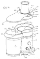
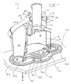
Figure 2 is a perspective view of a juicer with the lid off; -
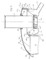
Figure 3 is a cross sectional view of the top of the juicer depicted inFigure 1 ; -
Figure 4 is a front cross sectional view of a juicer and pulp collector; -
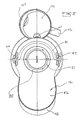
Figure 5 is a top plan view of the device depicted infigure 1 ; -
Figures 6 (a&b) are front and rear perspectives of a juice jug -
Figure 7 is a cross sectional view of the jug depicted infigures 6(a) and 6 (b) ; -
Figure 8 is a cross sectional view through the lid, feed tube and knife; -
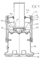
Figure 9 is a cross sectional view through the juicer; -
Figure 10 is a cross sectional view of the device depicted infigure 1 ; -
Figure 11 is a partially cross-sectioned view of a juicer, and a specially configured stand; -
Figure 12 is an exploded perspective view of a juicer according to teaching of the present invention; and -
Figure 13 is an exploded perspective of the lid. -
Figure 14 (a) is a perspective view of a pusher. -
Figure 14 (a) is a perspective view of a pusher, partially exploded. - As shown in
figure 1 , ajuicer 10 comprises a housing 11 alid 12 withfeed tube 51, apulp collector 13 and acollection jug 14, A motor within the housing spins agrating disk 20 located under thefeed tube 51. - The
housing 11 further consists of alower compartment 15 and an upper compartment orjuice collector 16. Thelower compartment 15 houses the juicer's motor, controls 17 and power supply. Thelower compartment 15 further includes alower rim 19 that is flared outward. For maximum stability, the device'sfeet 18 are mounted under theflared rim 19. In preferred embodiments, the feet have rubber bottoms in which are formed indentations 18a, as will be explained. - As shown in
figures 1-4 the upper compartment orjuice collector 16 is a removable component preferably fabricated from stainless steel. As seen infigure 3 , the interior compartment or collection reservoir 16a of thejuice collector 16 comprises a central opening 21 that is surrounded by anupturned rim 22. The collection reservoir of thejuice collector 16 is defined by anexterior wall 23. The upper extremity of the interior compartment is defined by ahorizontal rim 24 that surrounds acentral opening 25. Thisrim 24 prevents juice from escaping from, and pulp from entering the reservoir 16a. Integral with theexterior wall 23 andhorizontal rim 24 is ajuice stopping rim 26 which is inclined slightly from the vertical and which terminates in the 'U' or "J" shapedrim 27. - As shown better in
figure 2 , the juice-stoppingring 26 includes a pair ofopposed indentations 30 for locating tabs protruding from the underside of the lid to orientate the lid with respect to the juice collector. It will be observed that the juice-stoppingrim 26 does not completely surround the juice collector'ssidewall 23. Instead, the juice-stoppingring 26 includes a gap 32. The sides of the gap 32 are defined by the tapered or rolled off portions of 33 of the juice-stoppingring 26 and thereby define a spout. This spout further comprises a down turnedlip portion 34, which is shown infigure 3 and extends below the level of thehorizontal rim 24. Accordingly, agap 35 is formed between thelip 34 and thesidewall 23 that gap is able to accommodate a rim of thepulp collector 13 or a pulp disposal chute as will be further explained. These features provide for a highly efficient flow of waste pulp into thecollector 13 or chute. - As shown in
figures 1-4 and10 , thepulp collector 13 comprises a container with a generally 'D' shaped cross section that conforms to the exterior of thehousing 11. In preferred embodiments, theupper rim 40 of thepulp collector 13 includes an arcuate or concave portion adjacent (in use) to thehousing 11. As shown infigure 3 , theconcave portion 41 of therim 40 closely conforms to the outer surface of thesidewall 23 and fits into thegap 35 defined by thedescending lip 34 and thesidewall 23. Theupper rim 40 also includes anenlargement 42 that forms a convenient grip. In preferred embodiments one entire side of thepulp collector 13 is concave so to conform to the exterior shape of thehousing 11. It is also preferred that alower portion 43 of thecollector 13, adjacent thehousing 11 be indented so as to conform with the enlargedrim 19 of thehousing 11. Importantly, when thepulp collector 13 is in use, both thedescending lip 34 of the spout 32 and thesidewall portions 33 extend below the level of theupper rim 40 of thecollector 13. - The top inside surface of the
pulp collector 40 must closely fit the surfaces of the lid to prevent the leakage of air andfluids 52. This can make the pulp collector difficult to remove. To overcome this the interior of thepulp collector 40 also has one or more vertical ribs 140 near itrim 40 as shown inFigures 2 and3 . When thehandle 42 of the pulp collector is lifted, this rib acts on the cap as fulcrum to prevent the pulp container from jamming up onto the lid and causing thelip 41 to pivot downward so that the collector is easily removed. - The
lid 12 of the device provides several important functions. It prevents juice from escaping, it diverts pulp efficiently toward thecollector 13 or chute 150 (Figure 11 ), it cooperates with alocking bar 31 to keep the device safe and closed and it provides a platform for thefeed tube 51. As shown infigures 1-5 and8-11 , thelid 12 comprises a polymeric cap 52 (for example a polycarbonate) to which is secured a metal (preferably stainless steel)feed tube 51. As seen from above and as shown best infigure 5 , thecap 52 includes 2 primary lobes and assumes the shape of afigure "8 " when seen from above. The larger lobe primarily covers the juice collector and the smaller lobe primarily covers thepulp collector 13 orchute 150. Importantly the combination ofclear cap 52 and steel feed tube provides all of the advantages of both, that is, adequate strength in the feed tube and knife and the ability to see under the cap. - As shown in
figure 3 , the perimeter of thecap 52, where it contacts the interior of thepulp collector 13 orchute 150 is enlarged 55. Thisenlargement 55 serves to increase the contact area between thecap 52 and thechute 150 orcollector 13 while at the same time preserving a smooth and continuousinternal surface 56 that leads from the area above the juice collector to theexit area 57 of thecap 52. By providing a smooth, transitionless and continuously curvinginterior surface 56, thecap 52 assists in guiding pulp into thepulp collector 13 orchute 150 without creating air turbulence or discontinuities in the flow path of the pulp which tends to adhere to the under surface of the cap. The enlargement or rim thickening 55 also ensures there is no space or "well" above the surface for juice to collect and eventually get blown out. - As shown in
figure 2 , the cap also includes a descendingrim 57 that cooperates with the juice-stoppingrim 26 and generally follows its perimeter contour around the juice collector except in the area of the spout 32. As shown infigures 3-4 and8-11 , the descendingrim 57 of thelid 12 extends to the upper surface of thehorizontal rim 24 of thejuice collector 16 to form a seal. The angle between the outer surface of the descending rim and the inter surface of thejuice stopping ring 26 creates agap 70 because therim 57 is more vertical than thering 26. In preferred embodiments, this gap is tapered having its narrowest portion at the bottom and the widest portion at the top. In prior devices and where this gap has been too narrow, juice falling to the bottom of lid's rim would be blown by internal air pressure out of the gap and therefore out of the device. By providing a tapered gap, it is considered that lower air escape velocities and pressure drop within thegap 70, cause juice to collect in the gap rather than be expelled from it. This juice then drains into the pulp container via thejuice collector spout 32, 34. This makes the device easier to use and clean. The juice trapping capability of thelid 12 is enhanced by providing a horizontal shoulder 71 in the rim of the cap for the purpose of capping therim 27 of the juice-stopping ring. - The upper surface of the
cap 52 features a pair of opposed cam surfaces 59. Eachcam surface 59 includes aramp portion 60 and a detent 61. As is known in devices of this kind, a lockingbar 31 is mounted on apivot 62 that is adapted to both rotate and translate vertically as the underside of the lockingbar 31 rides up theramp 60. This motion of thepivot 62 trips a safety switch, preventing power from reaching the motor unless the lockingbar 31 is in it's closed position. - As previously mentioned, the lid also serves as a means of locating and supporting the
feed tube 51. In preferred embodiments thecap 52 is a transparent polymer such as a polycarbonate or SAN (a styrenic). As shown infigures 8-10 and12-13 , thecap 52 includes acentral opening 80 which accommodates a stainlesssteel feed tube 51. As shown in those figures, the lower interior of thetube 51 is equipped with a taperedknife 81 that is welded into or onto thetube 51. Because thegap 82 between the bottom of the feed tube 83 and the cutting disc at the base of thefilter basket 84 is relatively small, theknife 81 helps to restrain large fruits such as apples from tumbling uncontrollably when being juiced by the filter basket. - As shown in
figure 13 , in order for thecap 52 to restrain thefeed tube 51, thefeed tube 51 is provided with acircumferential flange 85. Theflange 85 has through openings 86 through which pass threadedfasteners 87. A sealinggasket 88 fits between thefeed tube 51 and theinternal rim 89 of theopening 80. Thegasket 88 includes aneck 91 and a surroundingring 92. Theneck 91 seals between thefeed tube 51 and the opening'svertical rim 89. Thering portion 92 seals between theflange 85 and the top of thecap 52. Thering portion 92 of the gasket also includes through-openings 93 through which thefasteners 87 pass. Thefasteners 87 may also pass through recesses 94 formed in the periphery of theopening 80 so as to extend intoscrew bosses 95 formed in a retainingring 96 which sits below thecap 52. In this way thegasket 88 is sandwiched in between the feed tube'sflange 85 and the retainingring 96. In preferred embodiments, thering 96 is made from nylon or another tough plastic that is resistant to cracking and crack propagation. This combination of materials ensures the lid assembly is dishwasher safe. - Also note that the
feed tube 51 carries two distinct orientation markers that assist in the proper location of the pusher. Afirst marker 97 is physically formed on the upper rim of thefeed tube 51 and a second marker comprises anopening 98 such as a triangular opening formed in theflange 85. Theopening 98 cooperates with a similarly shapedbulge 99 formed on the upper surface of thegasket 88. In this way thebulge 99 resides within and is visible in theopening 98 and provides a visual contrast to the stainless steel finish of theflange 85. The first marker interferes with the insertion of the pusher unless the pusher is oriented properly. As shown infigure 14 , thepusher 200 is sized to enter thefeed tube 51, but only when the pusher'slongitudinal slot 201 is aligned with theknife 81. Thus thefirst marker 97 is aligned with the knife and is able to enter theslot 201. Thebottom 202 of the slot is enlarged to make inserting the pusher into the feed tube easier. So that the pusher has a better feel, the upper knob orbulb 203 is enlarged, provided with arubber grip ring 204 and also provided with an internal weight such as a metal disk 205. - As shown in
figures 1 ,6 ,7 and10 , the utility of the juicer is enhanced by providing a specially configuredcollection jug 14. As suggested byfigure 1 , thejuice collection compartment 16 includes atubular output 100 that exits the juice collector from a low point. Thejug 14 comprises abody 101, ahandle 102 and alid 103. Thehandle 102 defines the rear of the jug. Opposite thehandle 102, the jug has aspout 104 that defines the front of the jug. Thelid 103 has a scalloped exit orrelief portion 105 that is generally in alignment with thespout 104. Integral with thelid 103 and located generally below the scallopedportion 105, the lid also includes a pourshield 106. As shown infigure 7 , theshield 106 extends downwardly from the under-surface of thelid 103 and forms anentry opening 107 that leads to thespout 104. The bulk of liquids being poured from the jug pass through theentry opening 107 and are generally inhibited from any other flow path because of the line contact between thesides 108 of the shield and the interior surface 109 of the jug. In this way, foam which may appear on the surface of fruit and vegetable juices is not dispensed while liquids from below the surface are able to enter theentry opening 107 and exit through the scallopedportion 105. The lid also has asecond relief 110 that cooperates with agap 112 in the upper rim of thejug 14 to form a port that theoutput spout tube 100 can enter. Note that the gap or juice entry point is located on the side of the jug and therefore does not interfere with the handle or spout. The orientation of thisgap 112 is not on the jug centerline, but closer to the handle so when the jug is tilted on an angle for pouring the level of juice with respect to thisgap 112 lowers and therefore does not leak from the gap when the jug is poured. The bottom of thejug 130, in the area under thegap 112 is relieved so that the jug can straddle the housing'srim 19. This allows the jug to be located nearer to the housing. After pouring the juice from thespout 104, the remaining foam/froth can be poured from the jug without removing the cap though thegap opening 112. - As shown in
figure 11 a benchtop mounting tray 120 may be used in conjunction with thejuicer 10 of the present invention. The pressed steel or moulded tray has three primary functions. It stabilises the juicer from excessive movement on the bench top, it locates the juicer over a discharge opening for pulp disposal and it collects fluid drippings. - The tray comprises a
contoured surface 121 in which is formeddrain channels 122.Rear channels 123 are formed in the area that surrounds thejug 14. A central channel conforms to the underside of thehousing 11. Anisland 125 with acentral depression 126 is formed centrally of the tray. Thefront end 127 of the tray includes anexit opening 128 that is defined by a cylindrical guide orcollar 129 that extends below the bottom surface of the tray. The collar fits into a cooperating hole in a bench top and thereby serves to locate thecollar 129 and thus the tray with respect to the hole in the bench top.Bumps 130 formed on the upper surface of the tray interlock with cooperating depressions 18a formed into thefeet 18. In this way, the juicer's housing positively interlocks with the tray. This same arrangement can be provided in the converse, that is, with bumps on the feet and depressions in the tray. In this way, juice drippings are collected in thechannels island 125 so as to avoid the motor's exhaust and run into thedischarge opening 129. With the housing properly located on the tray, thedischarge opening 129 lies directly below the smaller lobe of thecap 52. In this way a discharge cylinder orchute 150 may be attached to the rim of the cap and extend into engagement with or pilot into thedischarge opening 129. This allows pulp waste to be discharged directly from the juicer through the bench top into a conduit or waste receptacle.
Claims (17)
- A lid (12) for an electric juicing device (10), wherein the lid (12) comprises a polymeric cap (52) with a feed tube (51), characterised in that the cap (52) is formed with an opening (80) therein, and that the feed tube is a metal feed tube (51) attached to the cap (52) within the opening (80).
- The lid (12) of claim 1, wherein a metal knife (81) is attached to the interior of the feed tube (51).
- The lid (12) of either claim 1 or claim 2, wherein the feed tube (51) has a circumferential flange (85) that is affixed to the cap (52).
- The lid (12) of claim 3, wherein a gasket (88) is interposed between the flange (85) and the cap (52).
- The lid (12) of claim 4, wherein the gasket (88) comprises a neck (91) and a surrounding ring (92), the neck (91) sealing between the feed tube (51) and a vertical rim (89) of the cap (52).
- The lid (12) of either claim 3 or claim 4, wherein fasteners (87) extend through the flange (85) into a retaining ring (96) which is located adjacent to an underside (56) of the cap (52).
- The lid (12) of claim 6, wherein the fasteners (87) extend through the flange (85), the gasket (88) and the cap (52) into the retaining ring (96).
- The lid (12) of any one of claims 1 - 7, wherein the cap (52) has an undersurface that forms a smooth and continuous surface (56) which extends from above a juice collection area (21) to a pulp exit area (57) of the cap (52).
- An electric juicing device (10) comprising a lid (12) according to any one of claims 1-8, and a housing (11), wherein the housing has within it a rotating grating disk (20) located beneath the feed tube (51).
- The juicing device of claim 9, wherein the cap (52) includes a descending rim (57) that cooperates with a juice stopping rim (26) of a juice collector (16).
- The juicing device (10) of claim 10, wherein there is a gap (70) between the juice stopping rim (26) and the descending rim (26) of the cap (52).
- The juicing device (10) of claim 11, wherein the gap (70) is tapered.
- The juicing device of claim 11 or claim 12, wherein the gap (70) is narrow at a bottom of the gap and wider at a top of the gap.
- The juicing device (10) of any one of claims 11 - 13, wherein a second gap (32) is formed between a descending lip portion (34) of the housing (11) and a sidewall (23) of the juice collector (16), the second gap (32) being adapted to accommodate a pulp collector (13) so that the descending lip (34) enters the pulp collector (13).
- The juicing device (10) of claim 14, wherein the pulp collector (13) has a generally "D" shaped cross section and conforms to an exterior surface of the housing (11).
- The juicing device of any one of claims 11 -15, wherein the upper extent of the gap is further defined by a horizontal rim (24) formed in the cap (52).
- The juicing device of any one of claims 9 - 16, wherein an upper surface of the cap (52) further comprises at least one cam surface (59) and detent (61) for receiving a locking bar (31).
Applications Claiming Priority (2)
| Application Number | Priority Date | Filing Date | Title |
|---|---|---|---|
| AU2003903367A AU2003903367A0 (en) | 2003-07-02 | 2003-07-02 | Juicer |
| PCT/AU2004/000828 WO2005002404A1 (en) | 2003-07-02 | 2004-06-24 | Juicer |
Publications (3)
| Publication Number | Publication Date |
|---|---|
| EP1648273A1 EP1648273A1 (en) | 2006-04-26 |
| EP1648273A4 EP1648273A4 (en) | 2007-11-28 |
| EP1648273B1 true EP1648273B1 (en) | 2009-08-26 |
Family
ID=31983001
Family Applications (1)
| Application Number | Title | Priority Date | Filing Date |
|---|---|---|---|
| EP04737452A Expired - Lifetime EP1648273B1 (en) | 2003-07-02 | 2004-06-24 | Juicer |
Country Status (9)
| Country | Link |
|---|---|
| US (1) | US9220373B2 (en) |
| EP (1) | EP1648273B1 (en) |
| CN (1) | CN1816298B (en) |
| AT (1) | ATE440524T1 (en) |
| AU (1) | AU2003903367A0 (en) |
| DE (1) | DE602004022822D1 (en) |
| NZ (1) | NZ544296A (en) |
| RU (1) | RU2340271C2 (en) |
| WO (1) | WO2005002404A1 (en) |
Families Citing this family (46)
| Publication number | Priority date | Publication date | Assignee | Title |
|---|---|---|---|---|
| AU2003903367A0 (en) | 2003-07-02 | 2003-07-17 | Breville Pty. Ltd. | Juicer |
| US10420362B2 (en) * | 2003-07-02 | 2019-09-24 | Breville Pty Limited | Juicer |
| CN2897080Y (en) * | 2006-04-21 | 2007-05-09 | 深圳市宝安区西乡镇臣田唐锋电器厂 | Upper-cover assembly of juice press |
| KR100755440B1 (en) * | 2006-06-21 | 2007-09-05 | 김영기 | Juice Juice |
| US7854194B2 (en) * | 2006-09-15 | 2010-12-21 | Breville Pty Limited | Juicer speed control |
| AU2012241163B2 (en) * | 2006-09-15 | 2014-11-27 | Breville Pty Limited | Juicer Speed Control |
| AU2007216770B2 (en) * | 2006-09-15 | 2012-09-27 | Breville Pty Limited | Juicer Speed Control |
| WO2009010897A2 (en) * | 2007-07-13 | 2009-01-22 | Koninklijke Philips Electronics N.V. | Spout arrangement for juice extractor |
| FR2923147B1 (en) * | 2007-11-07 | 2010-02-26 | Kuan Chih Lin | PISTON OF A FRUIT AND VEGETABLE PRESS |
| US8939070B2 (en) * | 2008-05-01 | 2015-01-27 | Electrical Investments Limited | Juicer |
| US8210101B2 (en) * | 2008-12-09 | 2012-07-03 | Lyu Jan Co., Ltd. | Safety device for juice extractor |
| GB2466996A (en) * | 2009-01-19 | 2010-07-21 | Kenwood Ltd | Centrifugal Juicers |
| GB2470002A (en) * | 2009-05-05 | 2010-11-10 | Kenwood Ltd | Juicer with non drip outlet duct |
| EP2248449A1 (en) * | 2009-05-08 | 2010-11-10 | Koninklijke Philips Electronics N.V. | Kitchen appliance |
| US8807022B2 (en) | 2009-10-12 | 2014-08-19 | Alan Backus | Devices and methods to disintegrate foods |
| US20130340633A1 (en) * | 2011-01-28 | 2013-12-26 | Pei-Hsing Wu | Juice extractor with brake protection device |
| CN201911853U (en) * | 2011-01-28 | 2011-08-03 | 亚弘(东莞)电器有限公司 | A juice extractor and its upper cover assembly |
| US20120192727A1 (en) * | 2011-01-28 | 2012-08-02 | Pei-Hsing Wu | Juice extractor with brake device |
| US9565872B2 (en) * | 2011-08-11 | 2017-02-14 | Breville Pty Ltd | Combination juicer blender |
| CN102342735B (en) * | 2011-09-30 | 2013-12-11 | 胡伟 | Squeezing type juicer |
| CN104320998B (en) * | 2012-11-13 | 2018-02-16 | 皇家飞利浦有限公司 | Juice extractor |
| KR101300464B1 (en) * | 2013-01-14 | 2013-08-28 | 주식회사 엔유씨전자 | Juice extraction module for juice |
| US9675101B2 (en) * | 2013-03-15 | 2017-06-13 | Whirlpool Corporation | High performance adjustable juicer with whole foods feed chute |
| US20160037822A1 (en) * | 2013-04-23 | 2016-02-11 | Breville Pty Limited | Dual Drive Juicer |
| AU2014324069B2 (en) * | 2013-09-17 | 2019-11-07 | Breville Pty Limited | Improved fruit and vegetable juicer |
| BR102014009594B1 (en) * | 2014-04-22 | 2019-12-10 | Mendes Neto Carlos | improvements in juice extraction machine |
| RU2685849C2 (en) * | 2014-05-22 | 2019-04-23 | Бревилл Пти Лимитед | Jug for juicer |
| US20160000136A1 (en) * | 2014-07-02 | 2016-01-07 | Hamilton Beach Brands, Inc. | Juice Extractor |
| US10045663B2 (en) * | 2014-11-13 | 2018-08-14 | Dongguan Fushiduo Electrics Co., Ltd. | Double-screen grinding mechanism and double-screen grinding juicer |
| CA2971809A1 (en) * | 2014-12-22 | 2016-06-30 | A.A.T. Agroindustry Advanced Technologies S.P.A. | Beverage vending machine |
| USD755580S1 (en) | 2015-02-20 | 2016-05-10 | Hamilton Beach Brands, Inc. | Juice extractor |
| US10349730B2 (en) | 2015-03-06 | 2019-07-16 | Hamilton Beach Brands, Inc. | Juicer Brush |
| USD814861S1 (en) * | 2016-05-10 | 2018-04-10 | Nostalgia Products Llc | Badge for electric appliances |
| GB2551162B (en) * | 2016-06-08 | 2022-03-09 | Kenwood Ltd | Detachable rib and stir tool for a mixing bowl |
| CN107960904B (en) * | 2016-10-20 | 2023-11-24 | 佛山市顺德区美的电热电器制造有限公司 | Material washing device, upper cover and cooking utensil |
| CN107960892B (en) * | 2016-10-20 | 2023-07-04 | 佛山市顺德区美的电热电器制造有限公司 | Washing units, lids and cooking utensils |
| CN108968086A (en) * | 2017-05-31 | 2018-12-11 | 橙果信息技术有限公司 | Automatic juice extractor |
| CN109567549B (en) * | 2017-09-28 | 2022-01-11 | 广东美的生活电器制造有限公司 | Food processor |
| CN108056660B (en) * | 2018-02-10 | 2020-07-21 | 浙江中超新材料股份有限公司 | Working method of household portable juice extractor |
| FR3083070B1 (en) * | 2018-06-28 | 2020-06-12 | Seb S.A. | ROTARY SHAKING DEVICE OF A BEVERAGE PREPARATION MACHINE HAVING A COUPLING SLEEVE |
| EP4110144A4 (en) * | 2020-02-28 | 2024-03-06 | Breville Pty Limited | A juicer |
| CN114376420A (en) * | 2021-02-20 | 2022-04-22 | 中山市丰申电器有限公司 | Transmission assembly for water-material separation multifunctional soybean milk machine |
| USD1013463S1 (en) * | 2021-06-29 | 2024-02-06 | Franklin Farrow | Herb and vegetable extruder |
| CN113331667B (en) * | 2021-07-20 | 2025-07-08 | 中山市峻国电器有限公司 | Juice extractor |
| US20240225361A1 (en) * | 2023-01-05 | 2024-07-11 | Blendtec, Inc. | Blender enclosure |
| ES2978033A1 (en) * | 2023-01-26 | 2024-09-04 | Zummo Innovaciones Mecanicas S A U | Blender (Machine-translation by Google Translate, not legally binding) |
Family Cites Families (21)
| Publication number | Priority date | Publication date | Assignee | Title |
|---|---|---|---|---|
| US2188362A (en) * | 1938-04-23 | 1940-01-30 | James E Krilow | Coring utensil |
| US2289656A (en) * | 1940-09-23 | 1942-07-14 | Knapp Monarch Co | Juicer mechanism |
| US2590237A (en) * | 1949-12-19 | 1952-03-25 | William A Doering | Juice extractor |
| GB852220A (en) * | 1958-06-26 | 1960-10-26 | Jura Electro Apparatus Works L | Improvements in or relating to juice extractors |
| DE1931634U (en) * | 1965-09-24 | 1966-01-27 | Siemens Elektrogeraete Gmbh | ELECTRIC KITCHEN MACHINE. |
| US4333393A (en) * | 1979-07-17 | 1982-06-08 | Robert Morton D.G. Limited | Pitching mechanism for lauter tun knives |
| DE8401972U1 (en) * | 1983-02-04 | 1984-04-26 | I.P.E. Nuova Bialetti S.p.A. Industria Prodotti Elettrodomestici, Crusinallo di Omegna, Novara | Household appliance for the pre-treatment of food |
| SU1329763A1 (en) * | 1986-04-08 | 1987-08-15 | Производственное Объединение "Южный Машиностроительный Завод" Им.Л.И.Брежнева | Juice extractor |
| FR2650496B1 (en) * | 1989-08-04 | 1995-01-27 | Moulinex Sa | CENTRIFUGE |
| US5495795A (en) * | 1991-12-20 | 1996-03-05 | Trillium Health Products, Inc. | Juice extractors |
| US5317964A (en) * | 1992-01-13 | 1994-06-07 | Prudhomme Malcolm J | Apparatus for reducing the fat content of fried foods |
| US5479851A (en) * | 1994-05-25 | 1996-01-02 | Breville Pty Ltd. | Fruit and vegetable juicer |
| US5524906A (en) * | 1994-07-18 | 1996-06-11 | Mascotech Tubular Products, Inc. | Gasket for exhaust system joint |
| US5636923A (en) * | 1996-05-16 | 1997-06-10 | Nejat-Bina; Iradj E. | Electric spiral blade recycle food mixer |
| US5784954A (en) * | 1996-06-03 | 1998-07-28 | Zaklad Produkcji Rynkowej Sp. Z O.O. | Juice extractor |
| US6050180A (en) * | 1998-11-05 | 2000-04-18 | Omega Products, Inc. | Fruit and vegetable juicer |
| US5924357A (en) * | 1999-01-19 | 1999-07-20 | Chen; Ming-Sung | Cover for fruit and vegetable juice extractor |
| US6202547B1 (en) * | 2000-08-25 | 2001-03-20 | Rong-Yuan Tseng | Juicer having two cutters |
| US6397736B1 (en) * | 2001-11-09 | 2002-06-04 | Rong-Yuan Tseng | Fruit and vegetable juice extractor |
| AU2003903367A0 (en) | 2003-07-02 | 2003-07-17 | Breville Pty. Ltd. | Juicer |
| AU2004253180B2 (en) | 2003-07-02 | 2008-08-21 | Breville Pty Limited | Juicer |
-
2003
- 2003-07-02 AU AU2003903367A patent/AU2003903367A0/en not_active Abandoned
-
2004
- 2004-06-24 EP EP04737452A patent/EP1648273B1/en not_active Expired - Lifetime
- 2004-06-24 DE DE602004022822T patent/DE602004022822D1/en not_active Expired - Lifetime
- 2004-06-24 NZ NZ544296A patent/NZ544296A/en not_active IP Right Cessation
- 2004-06-24 AT AT04737452T patent/ATE440524T1/en not_active IP Right Cessation
- 2004-06-24 RU RU2006102962/12A patent/RU2340271C2/en active
- 2004-06-24 CN CN200480018732.8A patent/CN1816298B/en not_active Expired - Lifetime
- 2004-06-24 US US10/562,025 patent/US9220373B2/en active Active
- 2004-06-24 WO PCT/AU2004/000828 patent/WO2005002404A1/en not_active Ceased
Also Published As
| Publication number | Publication date |
|---|---|
| NZ544296A (en) | 2009-01-31 |
| WO2005002404A1 (en) | 2005-01-13 |
| HK1089916A1 (en) | 2006-12-15 |
| RU2340271C2 (en) | 2008-12-10 |
| US20070056450A1 (en) | 2007-03-15 |
| EP1648273A1 (en) | 2006-04-26 |
| CN1816298A (en) | 2006-08-09 |
| DE602004022822D1 (en) | 2009-10-08 |
| EP1648273A4 (en) | 2007-11-28 |
| CN1816298B (en) | 2016-01-13 |
| ATE440524T1 (en) | 2009-09-15 |
| AU2003903367A0 (en) | 2003-07-17 |
| US9220373B2 (en) | 2015-12-29 |
| RU2006102962A (en) | 2006-07-10 |
Similar Documents
| Publication | Publication Date | Title |
|---|---|---|
| US9220373B2 (en) | Juicer | |
| US10420362B2 (en) | Juicer | |
| US8474375B2 (en) | Juicer arrangement | |
| KR101541829B1 (en) | Juicer comprising screw assembly | |
| EP3185729B1 (en) | Citrus lid for blender | |
| EP0981040A1 (en) | Combined measuring cup, funnel and strainer utensil | |
| US12582256B2 (en) | Juicer | |
| US20100232256A1 (en) | Lid for a mixing device | |
| CN113840781B (en) | Lid and container for carbonated drinks | |
| CN113679233B (en) | Pot and lid for juicer | |
| EP3644799B1 (en) | Drip filter coffee machine | |
| EP2427083A1 (en) | Kitchen appliance | |
| US6216968B1 (en) | Drainage system for a food processing machine | |
| KR20150047589A (en) | Kitchen Appliance for Placement on a Vessel, Kitchen Appliance Set, Comprising Kitchen Appliance and Various Functional Units | |
| CA2530865C (en) | Juicer | |
| AU2004253180B2 (en) | Juicer | |
| KR20190002091U (en) | Juice discharging cap, juice discharging assembly, and juice squeezing extractor) | |
| KR101510998B1 (en) | A housing comprising extracting housing rib | |
| HK1089916B (en) | Juicer | |
| KR200357015Y1 (en) | Juicer | |
| HK1024741A (en) | Combined measuring cup, funnel and strainer utensil | |
| HK1098316A1 (en) | Citrus reamer and press |
Legal Events
| Date | Code | Title | Description |
|---|---|---|---|
| PUAI | Public reference made under article 153(3) epc to a published international application that has entered the european phase |
Free format text: ORIGINAL CODE: 0009012 |
|
| 17P | Request for examination filed |
Effective date: 20060201 |
|
| AK | Designated contracting states |
Kind code of ref document: A1 Designated state(s): AT BE BG CH CY CZ DE DK EE ES FI FR GB GR HU IE IT LI LU MC NL PL PT RO SE SI SK TR |
|
| DAX | Request for extension of the european patent (deleted) | ||
| RIC1 | Information provided on ipc code assigned before grant |
Ipc: A47J 19/02 20060101AFI20050114BHEP Ipc: A47J 43/25 20060101ALI20070601BHEP |
|
| RIC1 | Information provided on ipc code assigned before grant |
Ipc: A47J 43/07 20060101ALI20070711BHEP Ipc: A47J 19/02 20060101AFI20050114BHEP Ipc: A47J 43/25 20060101ALI20070711BHEP |
|
| A4 | Supplementary search report drawn up and despatched |
Effective date: 20071026 |
|
| 17Q | First examination report despatched |
Effective date: 20080102 |
|
| GRAP | Despatch of communication of intention to grant a patent |
Free format text: ORIGINAL CODE: EPIDOSNIGR1 |
|
| GRAS | Grant fee paid |
Free format text: ORIGINAL CODE: EPIDOSNIGR3 |
|
| GRAA | (expected) grant |
Free format text: ORIGINAL CODE: 0009210 |
|
| AK | Designated contracting states |
Kind code of ref document: B1 Designated state(s): AT BE BG CH CY CZ DE DK EE ES FI FR GB GR HU IE IT LI LU MC NL PL PT RO SE SI SK TR |
|
| REG | Reference to a national code |
Ref country code: GB Ref legal event code: FG4D |
|
| REG | Reference to a national code |
Ref country code: CH Ref legal event code: EP |
|
| REG | Reference to a national code |
Ref country code: IE Ref legal event code: FG4D |
|
| REF | Corresponds to: |
Ref document number: 602004022822 Country of ref document: DE Date of ref document: 20091008 Kind code of ref document: P |
|
| PG25 | Lapsed in a contracting state [announced via postgrant information from national office to epo] |
Ref country code: AT Free format text: LAPSE BECAUSE OF FAILURE TO SUBMIT A TRANSLATION OF THE DESCRIPTION OR TO PAY THE FEE WITHIN THE PRESCRIBED TIME-LIMIT Effective date: 20090826 Ref country code: SE Free format text: LAPSE BECAUSE OF FAILURE TO SUBMIT A TRANSLATION OF THE DESCRIPTION OR TO PAY THE FEE WITHIN THE PRESCRIBED TIME-LIMIT Effective date: 20090826 Ref country code: FI Free format text: LAPSE BECAUSE OF FAILURE TO SUBMIT A TRANSLATION OF THE DESCRIPTION OR TO PAY THE FEE WITHIN THE PRESCRIBED TIME-LIMIT Effective date: 20090826 |
|
| PG25 | Lapsed in a contracting state [announced via postgrant information from national office to epo] |
Ref country code: PL Free format text: LAPSE BECAUSE OF FAILURE TO SUBMIT A TRANSLATION OF THE DESCRIPTION OR TO PAY THE FEE WITHIN THE PRESCRIBED TIME-LIMIT Effective date: 20090826 Ref country code: SI Free format text: LAPSE BECAUSE OF FAILURE TO SUBMIT A TRANSLATION OF THE DESCRIPTION OR TO PAY THE FEE WITHIN THE PRESCRIBED TIME-LIMIT Effective date: 20090826 |
|
| PG25 | Lapsed in a contracting state [announced via postgrant information from national office to epo] |
Ref country code: CY Free format text: LAPSE BECAUSE OF FAILURE TO SUBMIT A TRANSLATION OF THE DESCRIPTION OR TO PAY THE FEE WITHIN THE PRESCRIBED TIME-LIMIT Effective date: 20090826 Ref country code: PT Free format text: LAPSE BECAUSE OF FAILURE TO SUBMIT A TRANSLATION OF THE DESCRIPTION OR TO PAY THE FEE WITHIN THE PRESCRIBED TIME-LIMIT Effective date: 20091228 Ref country code: BG Free format text: LAPSE BECAUSE OF FAILURE TO SUBMIT A TRANSLATION OF THE DESCRIPTION OR TO PAY THE FEE WITHIN THE PRESCRIBED TIME-LIMIT Effective date: 20091126 |
|
| PG25 | Lapsed in a contracting state [announced via postgrant information from national office to epo] |
Ref country code: EE Free format text: LAPSE BECAUSE OF FAILURE TO SUBMIT A TRANSLATION OF THE DESCRIPTION OR TO PAY THE FEE WITHIN THE PRESCRIBED TIME-LIMIT Effective date: 20090826 Ref country code: DK Free format text: LAPSE BECAUSE OF FAILURE TO SUBMIT A TRANSLATION OF THE DESCRIPTION OR TO PAY THE FEE WITHIN THE PRESCRIBED TIME-LIMIT Effective date: 20090826 Ref country code: RO Free format text: LAPSE BECAUSE OF FAILURE TO SUBMIT A TRANSLATION OF THE DESCRIPTION OR TO PAY THE FEE WITHIN THE PRESCRIBED TIME-LIMIT Effective date: 20090826 Ref country code: CZ Free format text: LAPSE BECAUSE OF FAILURE TO SUBMIT A TRANSLATION OF THE DESCRIPTION OR TO PAY THE FEE WITHIN THE PRESCRIBED TIME-LIMIT Effective date: 20090826 Ref country code: ES Free format text: LAPSE BECAUSE OF FAILURE TO SUBMIT A TRANSLATION OF THE DESCRIPTION OR TO PAY THE FEE WITHIN THE PRESCRIBED TIME-LIMIT Effective date: 20091207 |
|
| REG | Reference to a national code |
Ref country code: CH Ref legal event code: NV Representative=s name: VOSSIUS & PARTNER |
|
| PG25 | Lapsed in a contracting state [announced via postgrant information from national office to epo] |
Ref country code: SK Free format text: LAPSE BECAUSE OF FAILURE TO SUBMIT A TRANSLATION OF THE DESCRIPTION OR TO PAY THE FEE WITHIN THE PRESCRIBED TIME-LIMIT Effective date: 20090826 |
|
| PG25 | Lapsed in a contracting state [announced via postgrant information from national office to epo] |
Ref country code: BE Free format text: LAPSE BECAUSE OF FAILURE TO SUBMIT A TRANSLATION OF THE DESCRIPTION OR TO PAY THE FEE WITHIN THE PRESCRIBED TIME-LIMIT Effective date: 20090826 |
|
| PLBE | No opposition filed within time limit |
Free format text: ORIGINAL CODE: 0009261 |
|
| STAA | Information on the status of an ep patent application or granted ep patent |
Free format text: STATUS: NO OPPOSITION FILED WITHIN TIME LIMIT |
|
| 26N | No opposition filed |
Effective date: 20100527 |
|
| PG25 | Lapsed in a contracting state [announced via postgrant information from national office to epo] |
Ref country code: GR Free format text: LAPSE BECAUSE OF FAILURE TO SUBMIT A TRANSLATION OF THE DESCRIPTION OR TO PAY THE FEE WITHIN THE PRESCRIBED TIME-LIMIT Effective date: 20091127 |
|
| PG25 | Lapsed in a contracting state [announced via postgrant information from national office to epo] |
Ref country code: MC Free format text: LAPSE BECAUSE OF NON-PAYMENT OF DUE FEES Effective date: 20100630 |
|
| PG25 | Lapsed in a contracting state [announced via postgrant information from national office to epo] |
Ref country code: IT Free format text: LAPSE BECAUSE OF FAILURE TO SUBMIT A TRANSLATION OF THE DESCRIPTION OR TO PAY THE FEE WITHIN THE PRESCRIBED TIME-LIMIT Effective date: 20090826 |
|
| PG25 | Lapsed in a contracting state [announced via postgrant information from national office to epo] |
Ref country code: IE Free format text: LAPSE BECAUSE OF NON-PAYMENT OF DUE FEES Effective date: 20100624 |
|
| PG25 | Lapsed in a contracting state [announced via postgrant information from national office to epo] |
Ref country code: HU Free format text: LAPSE BECAUSE OF FAILURE TO SUBMIT A TRANSLATION OF THE DESCRIPTION OR TO PAY THE FEE WITHIN THE PRESCRIBED TIME-LIMIT Effective date: 20100227 Ref country code: LU Free format text: LAPSE BECAUSE OF NON-PAYMENT OF DUE FEES Effective date: 20100624 |
|
| PG25 | Lapsed in a contracting state [announced via postgrant information from national office to epo] |
Ref country code: TR Free format text: LAPSE BECAUSE OF FAILURE TO SUBMIT A TRANSLATION OF THE DESCRIPTION OR TO PAY THE FEE WITHIN THE PRESCRIBED TIME-LIMIT Effective date: 20090826 |
|
| REG | Reference to a national code |
Ref country code: FR Ref legal event code: PLFP Year of fee payment: 13 |
|
| REG | Reference to a national code |
Ref country code: CH Ref legal event code: PFA Owner name: BREVILLE PTY LIMITED, AU Free format text: FORMER OWNER: BREVILLE PTY LIMITED, AU |
|
| REG | Reference to a national code |
Ref country code: FR Ref legal event code: PLFP Year of fee payment: 14 |
|
| REG | Reference to a national code |
Ref country code: FR Ref legal event code: PLFP Year of fee payment: 15 |
|
| REG | Reference to a national code |
Ref country code: FR Ref legal event code: PLFP Year of fee payment: 19 |
|
| PGFP | Annual fee paid to national office [announced via postgrant information from national office to epo] |
Ref country code: NL Payment date: 20230515 Year of fee payment: 20 Ref country code: FR Payment date: 20230523 Year of fee payment: 20 Ref country code: DE Payment date: 20230502 Year of fee payment: 20 |
|
| PGFP | Annual fee paid to national office [announced via postgrant information from national office to epo] |
Ref country code: GB Payment date: 20230504 Year of fee payment: 20 Ref country code: CH Payment date: 20230702 Year of fee payment: 20 |
|
| REG | Reference to a national code |
Ref country code: DE Ref legal event code: R071 Ref document number: 602004022822 Country of ref document: DE |
|
| REG | Reference to a national code |
Ref country code: NL Ref legal event code: MK Effective date: 20240623 |
|
| REG | Reference to a national code |
Ref country code: CH Ref legal event code: PL |
|
| PG25 | Lapsed in a contracting state [announced via postgrant information from national office to epo] |
Ref country code: GB Free format text: LAPSE BECAUSE OF EXPIRATION OF PROTECTION Effective date: 20240623 |
|
| REG | Reference to a national code |
Ref country code: GB Ref legal event code: PE20 Expiry date: 20240623 |
|
| PG25 | Lapsed in a contracting state [announced via postgrant information from national office to epo] |
Ref country code: GB Free format text: LAPSE BECAUSE OF EXPIRATION OF PROTECTION Effective date: 20240623 |