EP1648079A2 - System for transmitting motion between means separated by a wall - Google Patents
System for transmitting motion between means separated by a wall Download PDFInfo
- Publication number
- EP1648079A2 EP1648079A2 EP05022355A EP05022355A EP1648079A2 EP 1648079 A2 EP1648079 A2 EP 1648079A2 EP 05022355 A EP05022355 A EP 05022355A EP 05022355 A EP05022355 A EP 05022355A EP 1648079 A2 EP1648079 A2 EP 1648079A2
- Authority
- EP
- European Patent Office
- Prior art keywords
- shaft
- magnetic disc
- working
- carried
- partition wall
- Prior art date
- Legal status (The legal status is an assumption and is not a legal conclusion. Google has not performed a legal analysis and makes no representation as to the accuracy of the status listed.)
- Withdrawn
Links
- 230000033001 locomotion Effects 0.000 title claims abstract description 29
- 238000005192 partition Methods 0.000 claims abstract description 29
- 230000005540 biological transmission Effects 0.000 claims abstract description 12
- 230000008878 coupling Effects 0.000 claims abstract description 9
- 238000010168 coupling process Methods 0.000 claims abstract description 9
- 238000005859 coupling reaction Methods 0.000 claims abstract description 9
- 238000004320 controlled atmosphere Methods 0.000 claims abstract description 8
- 230000000087 stabilizing effect Effects 0.000 claims description 8
- 239000003638 chemical reducing agent Substances 0.000 description 4
- 238000000926 separation method Methods 0.000 description 2
- 239000003814 drug Substances 0.000 description 1
- 239000000696 magnetic material Substances 0.000 description 1
- 238000004519 manufacturing process Methods 0.000 description 1
- 238000005096 rolling process Methods 0.000 description 1
Images


Classifications
-
- H—ELECTRICITY
- H02—GENERATION; CONVERSION OR DISTRIBUTION OF ELECTRIC POWER
- H02K—DYNAMO-ELECTRIC MACHINES
- H02K49/00—Dynamo-electric clutches; Dynamo-electric brakes
- H02K49/10—Dynamo-electric clutches; Dynamo-electric brakes of the permanent-magnet type
- H02K49/104—Magnetic couplings consisting of only two coaxial rotary elements, i.e. the driving element and the driven element
- H02K49/108—Magnetic couplings consisting of only two coaxial rotary elements, i.e. the driving element and the driven element with an axial air gap
Definitions
- the present invention relates to transmission of motion between means situated in different areas, with a particular reference to the applications related to the motive power transmission from a first area to a controlled atmosphere environment.
- the document EP 1.239.572 describes a device for transmitting rotation motion, by magnetic coupling, between mechanically disjoined elements, separated by an empty space.
- the document DE 198 26 065 shows a rapid detaching, multiple dispensing head for syringes or laboratory pipettes, with a magnetic coupling between the power means and the head.
- the document EP 0.210.557 teaches to produce a front magnetic coupling device, aimed at transmitting a torque from a first to a second environment, which are hermetically separated by a air-tight partition wall; the use of this device is particularly advantageous for medicaments administering.
- the object of the present invention is to propose a system for transmitting motion between means separated by a partition wall, which is aimed at transmitting motion, also combined by rotation and horizontal translation motions, in a direction parallel to the wall, between an power means member, situated in a first area, and working means, situated in a controlled atmosphere environment, defined by a chamber insulated from the outside by means, of which the partition wall is an integral part.
- Another object of the present invention is to propose a system for transmitting motion between means separated by a partition wall, which is aimed at transmitting motion, also combined by rotation and horizontal translation motions, in a direction parallel to the wall, between an power means member, situated in a first area, and working means, situated in a second area, delimited by the partition wall.
- a further object of the present invention is to propose a system for transmitting motion between means separated by a partition wall, so that the motion transmitted from an power means member to relative working means, with the partition wall interposed therebetween, allows a rational and immediate use of the so transferred mechanical energy.
- a still further object of the present invention is to propose a system for transmitting motion between means separated by a partition wall, whose concept is simple and whose production costs are relatively contained.
- the reference numeral 3 indicates an power means, carried by first guiding means 1, for example arranged horizontal , and including a slide 1a, which carries, fastened thereto the power means 3, that can slide on a relative horizontal guide 1b.
- the power means 3 is connected to a unit 4, which is capable of moving the power means along the horizontal guiding means 1: the above mentioned unit 4, see Figure 2, includes e.g. a first endless conveyor 4a, whose lower run 4c is fastened to the slide 1a, by known means.
- the endless conveyor is operated by a motor group 4b.
- the power means 3 rotate a first shaft 5a, carrying, keyed onto its ends, a first magnetic disc 6a, which is magnetically coupled with a second magnetic disc 6b.
- a partition wall 7, of non magnetic material, which cannot be magnetized, is interposed between the first and second magnetic discs.
- the horizontal guide 1a is parallel to the wall 7.
- Figures 3a, 3b show two possible embodiments defining the type of magnetic coupling, which can be obtained, respectively, by electromagnets mounted on the first disc 6a, or by permanent magnets fastened to both discs, first disc 6a and second disc 6b.
- Figure 4 is a top view of the arrangement of the permanent magnets, according to the variant of the first magnetic disc 6a, shown in Figure 3b.
- the second magnetic disc 6b is keyed onto the end of a main shaft 5b, carried by a structure 20, see Figure 2, which will be discussed later on.
- the main shaft 5b is coaxial with the first shaft 5a and is connected, by a speed reducer 9, to a second shaft 5c, which supplies a first torque C1.
- the second shaft 5c carries, keyed thereon, a first pulley 11a, which belongs to a second endless conveyor 11, aimed at moving a translation unit 10, fastened in known way to one of the conveyor runs, and at supplying a second torque C2 onto a relative second pulley 11b of the conveyor 11.
- the second torque C2 depending on the first torque C1 and on the geometrical relations characterizing the conveyor 11, is transmitted to a third shaft 5d, onto which the second pulley 11b is keyed.
- the second shaft 5c and third shaft 5d supply corresponding torques C1, C2, which are applied to working means, not shown in the Figures.
- the group defined by the second magnetic disc 6b, the main shaft 5b, the speed reducer 9, the second and third shafts 5c, 5d, and by the second conveyor 11, is carried by the structure 20, sliding on second guiding means 2.
- the structure 20 forms a sleeve 2a, which can slide along a stem 2b, arranged with a horizontal axis and being parallel to the partition wall 7 and fastened to a frame, not shown.
- the system includes also stabilizing and anti-rotation means 12 of the structure 20, formed by two rolls carried idle by the latter, distributed above and below the second magnetic disc 6b, and aimed at going in abutment against the partition wall 7 with the rolling surfaces.
- the first group formed by the power means 3, the first horizontal guiding means 1, the first conveyor 4, the motorized group 4b, the first shaft 5a and the first magnetic disc 6a, shown on the left of the partition wail 7 in Figure 2, is contained in a first area.
- the second group formed by the second magnetic disc 6b, the main shaft 5b, the speed reducer 9, the second shaft 5c and third shaft 5d, the second conveyor 11, the translation unit 10, the structure 20, the stabilizing and anti-rotation means 12, the second horizontal guide means 2 and the working means, not shown, connected to the second shaft 5c and third shaft 5d, as shown on the right of Figure 2, are contained in a controlled atmosphere environment, e.g. sterile, defined by a chamber, not shown, separated from the outside by means, to which belongs the partition wall 7.
- a controlled atmosphere environment e.g. sterile, defined by a chamber, not shown, separated from the outside by means, to which belongs the partition wall 7.
- the above mentioned second group excluding the second magnetic disc 6b, defines working means 30, aimed at using the mechanical energy supplied by the second magnetic disc 6b.
- the operation of the power means 3 determines the transmission of a rotating motion from the first shaft 5a to the main shaft 5b due to the magnetic coupling between the first magnetic disc 6a and the second magnetic disc 6b, to which a torque C is transmitted.
- the speed reducer 9 reduces the angular speed of the main shaft 5b and at the same time, increases the torque value from a value C to a value C1 on the second shaft 5c, associated to the previous value by known relations.
- the operation of the first conveyor 4 by the motorized group 4b, allows the power means 3 to translate longitudinally along the first horizontal guiding means 1, to which the contextual translation of the structure 20 corresponds, in the same direction .
- the structure 20 slides along the stem 2b due to the force transmitted to the second magnetic disc 6b by the magnetic coupling defined therein.
- first magnetic disc 6a and the second magnetic disc 6b slide along the relative surfaces of the partition wall 7, remaining opposite to each other.
- the stabilizing and anti-rotation means 12 keep the translation of the structure 20 parallel to the one of the power means 3, since it excludes any rotation of the structure 20 with respect to the axis of the stem 2b, stabilizing also its motion.
- the proposed system allows a clear physical separation between the first area, where the potentially polluting means work, and the controlled atmosphere environment, e.g. sterile, which requires the "dry” means operation, which consequently do not change its state.
- the illustrated example describes two embodiments of the working means 30; it is understood that the rotation-translation of the second shaft 5c can be used in any way, to operate working groups of any conformation and fulfilling specific functions.
- the translation unit 10 can be formed by a nozzles carrying group, made move vertically to introduce and remove the nozzles into and from bottles carried by a conveyor situated below and motorized continuously, with the group being operated horizontally in a back and forth motion (in order to translate horizontally the working means 30) with the forth stroke velocity equal to the conveyor velocity.
- the proposed system can be also advantageously used in the applications, in which the partition wall acts only as separation means between the two different areas, the one containing the working means not being controlled atmosphere environment; therefore, the present invention is characterized by a versatility, which allows its introduction in numerous technical applications.
Landscapes
- Engineering & Computer Science (AREA)
- Power Engineering (AREA)
- Dynamo-Electric Clutches, Dynamo-Electric Brakes (AREA)
Abstract
Description
- The present invention relates to transmission of motion between means situated in different areas, with a particular reference to the applications related to the motive power transmission from a first area to a controlled atmosphere environment.
- There are different technical fields, which use the transmission of a torque, or of a power, between two different areas, separated by a partition element for various reasons.
- There are also many applications, which require carrying the mechanical energy to controlled atmosphere environments, e.g. sterile or subjected to preestablished controlled pressure and temperature values.
- The document EP 1.239.572 describes a device for transmitting rotation motion, by magnetic coupling, between mechanically disjoined elements, separated by an empty space.
- The document DE 198 26 065 shows a rapid detaching, multiple dispensing head for syringes or laboratory pipettes, with a magnetic coupling between the power means and the head.
- The document EP 0.210.557 teaches to produce a front magnetic coupling device, aimed at transmitting a torque from a first to a second environment, which are hermetically separated by a air-tight partition wall; the use of this device is particularly advantageous for medicaments administering.
- The object of the present invention is to propose a system for transmitting motion between means separated by a partition wall, which is aimed at transmitting motion, also combined by rotation and horizontal translation motions, in a direction parallel to the wall, between an power means member, situated in a first area, and working means, situated in a controlled atmosphere environment, defined by a chamber insulated from the outside by means, of which the partition wall is an integral part.
- Another object of the present invention is to propose a system for transmitting motion between means separated by a partition wall, which is aimed at transmitting motion, also combined by rotation and horizontal translation motions, in a direction parallel to the wall, between an power means member, situated in a first area, and working means, situated in a second area, delimited by the partition wall.
- A further object of the present invention is to propose a system for transmitting motion between means separated by a partition wall, so that the motion transmitted from an power means member to relative working means, with the partition wall interposed therebetween, allows a rational and immediate use of the so transferred mechanical energy.
- A still further object of the present invention is to propose a system for transmitting motion between means separated by a partition wall, whose concept is simple and whose production costs are relatively contained.
- The above mentioned objects are obtained in accordance with the contents of the claims.
- The characteristic features of the invention, not resulting from what has just been said, will be better pointed out in the following, in accordance with the contents of claims and with help of the enclosed figures, in which:
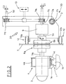
- Figure 1 is a schematic, perspective view of the proposed system;
- Figure 2 is a front, detailed view of a second embodiment;
- Figures 3a, 3b show a particular of Figure 2, according to two possible embodiments;
- Figure 4 is a top view of an element of Figure 3b.
- Having regards to the above Figures, the
reference numeral 3 indicates an power means, carried by first guidingmeans 1, for example arranged horizontal , and including aslide 1a, which carries, fastened thereto the power means 3, that can slide on a relativehorizontal guide 1b. - The power means 3 is connected to a unit 4, which is capable of moving the power means along the horizontal guiding means 1: the above mentioned unit 4, see Figure 2, includes e.g. a first
endless conveyor 4a, whose lower run 4c is fastened to theslide 1a, by known means. The endless conveyor is operated by amotor group 4b. - The power means 3 rotate a
first shaft 5a, carrying, keyed onto its ends, a firstmagnetic disc 6a, which is magnetically coupled with a secondmagnetic disc 6b. Apartition wall 7, of non magnetic material, which cannot be magnetized, is interposed between the first and second magnetic discs. - The
horizontal guide 1a is parallel to thewall 7. - Figures 3a, 3b show two possible embodiments defining the type of magnetic coupling, which can be obtained, respectively, by electromagnets mounted on the
first disc 6a, or by permanent magnets fastened to both discs,first disc 6a andsecond disc 6b. - Figure 4 is a top view of the arrangement of the permanent magnets, according to the variant of the first
magnetic disc 6a, shown in Figure 3b. - The second
magnetic disc 6b is keyed onto the end of amain shaft 5b, carried by astructure 20, see Figure 2, which will be discussed later on. - The
main shaft 5b is coaxial with thefirst shaft 5a and is connected, by aspeed reducer 9, to asecond shaft 5c, which supplies a first torque C1. - The
second shaft 5c carries, keyed thereon, afirst pulley 11a, which belongs to a secondendless conveyor 11, aimed at moving atranslation unit 10, fastened in known way to one of the conveyor runs, and at supplying a second torque C2 onto a relativesecond pulley 11b of theconveyor 11. - The second torque C2, depending on the first torque C1 and on the geometrical relations characterizing the
conveyor 11, is transmitted to athird shaft 5d, onto which thesecond pulley 11b is keyed. - The
second shaft 5c andthird shaft 5d supply corresponding torques C1, C2, which are applied to working means, not shown in the Figures. - The group defined by the second
magnetic disc 6b, themain shaft 5b, the speed reducer 9, the second andthird shafts second conveyor 11, is carried by thestructure 20, sliding on second guidingmeans 2. - In particular, the
structure 20 forms asleeve 2a, which can slide along astem 2b, arranged with a horizontal axis and being parallel to thepartition wall 7 and fastened to a frame, not shown. - The system includes also stabilizing and anti-rotation means 12 of the
structure 20, formed by two rolls carried idle by the latter, distributed above and below the secondmagnetic disc 6b, and aimed at going in abutment against thepartition wall 7 with the rolling surfaces. - The first group formed by the power means 3, the first horizontal guiding means 1, the first conveyor 4, the
motorized group 4b, thefirst shaft 5a and the firstmagnetic disc 6a, shown on the left of thepartition wail 7 in Figure 2, is contained in a first area. - The second group formed by the second
magnetic disc 6b, themain shaft 5b, the speed reducer 9, thesecond shaft 5c andthird shaft 5d, thesecond conveyor 11, thetranslation unit 10, thestructure 20, the stabilizing and anti-rotation means 12, the second horizontal guide means 2 and the working means, not shown, connected to thesecond shaft 5c andthird shaft 5d, as shown on the right of Figure 2, are contained in a controlled atmosphere environment, e.g. sterile, defined by a chamber, not shown, separated from the outside by means, to which belongs thepartition wall 7. - It is specified that the above mentioned second group, excluding the second
magnetic disc 6b, defines workingmeans 30, aimed at using the mechanical energy supplied by the secondmagnetic disc 6b. - Now the operation of the system proposed by the present invention will be described.
- The operation of the power means 3 determines the transmission of a rotating motion from the
first shaft 5a to themain shaft 5b due to the magnetic coupling between the firstmagnetic disc 6a and the secondmagnetic disc 6b, to which a torque C is transmitted. - The
speed reducer 9 reduces the angular speed of themain shaft 5b and at the same time, increases the torque value from a value C to a value C1 on thesecond shaft 5c, associated to the previous value by known relations. - This allows to use the mechanical energy supplied by the
second shaft 5c in various ways, besides the direct connection of first working means, not shown, it is also possible to operate thesecond conveyor 11; in this case, it is possible to connect second working means, likewise not shown, to thethird shaft 5d, onto which thesecond pulley 11b is keyed, as well as to fasten atranslation unit 10 to a run of thesecond conveyor 11, in order to transmit a linear motion to a moving element, not shown. - The operation of the first conveyor 4 by the
motorized group 4b, allows the power means 3 to translate longitudinally along the firsthorizontal guiding means 1, to which the contextual translation of thestructure 20 corresponds, in the same direction . - The
structure 20 slides along thestem 2b due to the force transmitted to the secondmagnetic disc 6b by the magnetic coupling defined therein. - In this way, the first
magnetic disc 6a and the secondmagnetic disc 6b slide along the relative surfaces of thepartition wall 7, remaining opposite to each other. - The stabilizing and anti-rotation means 12 keep the translation of the
structure 20 parallel to the one of the power means 3, since it excludes any rotation of thestructure 20 with respect to the axis of thestem 2b, stabilizing also its motion. - It results obvious from the above considerations that the proposed system can allow to transmit the rotary motion, horizontal translation motion, as well as the combination of the two previous motions between the power means 3 and the working
means 30 operated by the secondmagnetic disc 6b, thus obtaining the objects and being of simple concept and relatively cheap. - Moreover, the proposed system allows a clear physical separation between the first area, where the potentially polluting means work, and the controlled atmosphere environment, e.g. sterile, which requires the "dry" means operation, which consequently do not change its state.
- The illustrated example describes two embodiments of the working
means 30; it is understood that the rotation-translation of thesecond shaft 5c can be used in any way, to operate working groups of any conformation and fulfilling specific functions. - For instance, the
translation unit 10 can be formed by a nozzles carrying group, made move vertically to introduce and remove the nozzles into and from bottles carried by a conveyor situated below and motorized continuously, with the group being operated horizontally in a back and forth motion (in order to translate horizontally the working means 30) with the forth stroke velocity equal to the conveyor velocity. - The proposed system can be also advantageously used in the applications, in which the partition wall acts only as separation means between the two different areas, the one containing the working means not being controlled atmosphere environment; therefore, the present invention is characterized by a versatility, which allows its introduction in numerous technical applications.
Claims (17)
- System for transmitting motion between means separated by a partition wall, characterized in that it includes: power means (3), operating a first magnetic disc (6a), which faces said partition wall (7); a second magnetic disc (6b), opposite to said first magnetic disc (6a) and separated therefrom by said partition wall (7), with said second magnetic disc (6b) connected to at least one working member (30) and defining a magnetic coupling with said first magnetic disc (6a) to allow the transmission of the motion from said power means (3) to said working means (30), said second magnetic disc (6b) and working means (30) being situated in a controlled atmosphere environment, defined by a chamber, separated from outside by means, to which said partition wall (7) belongs.
- System, as claimed in claim 1, characterized in that said power means (3) rotates a first shaft (5a), which carries, keyed onto its end, said first magnetic disc (6a), in order to transmit the rotation motion between said power means (3) and working means (30).
- System, as claimed in claim 1, characterized in that said power means (3) is carried by first guiding means (1) and is subjected to a relative unit (4) for moving the power means (3) along said first guiding means (1) and in that said working means (30) are carried by a structure (20), which slides on second guiding means (2), in order to allow its relative motion, as a consequence of translation of said power means (3) along the first guiding means (1).
- System, as claimed in claim 3, characterized in that said second guiding means (2) include a sleeve (2a), which is carried by said structure (20), and which couples with a stem (2b) fastened to a frame situated in said chamber, so that said structure (20), carrying said working means (30), slide due to translation of said power means (3) along said first guiding means (1).
- System, as claimed in claim 4, characterized in that said working means (30) has stabilizing and anti-rotation means (12), fastened to said structure (20).
- System, as claimed in claim 3, characterized in that said working means (30) includes at least a second shaft (5c), carried by said structure (20) with possibility of rotation and operated by said second magnetic disc (6b).
- System, as claimed in claim 3, characterized in that said working means (30) include at least one second shaft (5c), operated by said second magnetic disc (6b), and at least one third shaft (5d), connected to the second shaft (5c) by an endless transmission element (11), with said second shaft (5c) and third shaft (5d) carried by said structure (20) with possibility of rotation.
- System, as claimed in claim 3, characterized in that said working means (30) include at least one second shaft (5c), operated by said second magnetic disc (6b), and at least one third shaft (5d), connected to the second shaft (5c) by an endless transmission element (11), and at least one translation unit (10), fastened to one of the runs of said transmission element (11), with said second shaft (5c) and third shaft (5d) carried by said structure (20) with possibility of rotation.
- System, as claimed in claim 5, characterized in that said stabilizing and anti-rotation means (12) include at least two rolls (12a, 12b), carried idle by said structure (20), and going in abutment against the partition wall (7).
- System for transmitting motion between means separated by a partition wall, characterized in that it includes: power means (3), carried by first guiding means (1) and connected to a relative unit (4) for being moved along said first guiding means (1), said power means (3) moving a first magnetic disc (6a), opposite to said partition wall (7); a second magnetic disc (6b), opposite to said first magnetic disc (6a) and separated therefrom by said partition wall (7), with said second magnetic disc (6b) being connected to at least one working member (30), carried by a structure (20), which slides on second guiding means (20), said second magnetic disc (6b) coupling magnetically with said first magnetic disc (6a), so as to transmit the motion from said power means (3) to said working means (30), as well as the translation of the structure (20), which carries the latter due to the motion of said power means (3) along said first guiding means (1).
- System, as claimed in claim 10, characterized in that said power means (3) drives to rotate a first shaft (5a), which carries, keyed onto its end, said first magnetic disc (6a), in order to transmit the rotation motion between said power means (3) and working means (30).
- System, as claimed in claim 10, characterized in that the second guiding means (2) include a sleeve (2a), which is carried by said structure (20), and which couples with a stem (2b) fastened to a frame, so that said structure (20), carrying said working means (30), slide due to the translation of said power means (3) along said first guiding means (1).
- System, as claimed in claim 12, characterized in that said working means (30) has stabilizing and anti-rotation means (12), fastened to said structure (20).
- System, as claimed in claim 10, characterized in that said working means (30) includes at least a second shaft (5c), carried by said structure (20) with possibility of rotation and operated by said second magnetic disc (6b).
- System, as claimed in claim 10, characterized in that said working means (30) include at least one second shaft (5c), operated by said second magnetic disc (6b), and at least one third shaft (5d), connected to the second shaft (5c) by an endless transmission element (11), with said second shaft (5c) and third shaft (5d) carried by said structure (20) with possibility of rotation.
- System, as claimed in claim 10, characterized in that said working means (30) include at least one second shaft (5c), operated by said second magnetic disc (6b), and at least one third shaft (5d), connected to the second shaft (5c) by an endless transmission element (11), and at least one translation unit (10), fastened to one of the runs of said transmission element (11), with said second shaft (5c) and third shaft (5d) carried by said structure (20) with possibility of rotation.
- System, as claimed in claim 13, characterized in that said stabilizing and anti-rotation means (12) include at least two rolls (12a, 12b), carried idle by said structure (20), and going in abutment against the partition wall (7).
Applications Claiming Priority (1)
| Application Number | Priority Date | Filing Date | Title |
|---|---|---|---|
| IT000629A ITBO20040629A1 (en) | 2004-10-14 | 2004-10-14 | SYSTEM FOR THE TRANSMISSION OF THE BIKE BETWEEN ORGANS SEPARATED FROM A DIVIDING WALL |
Publications (2)
| Publication Number | Publication Date |
|---|---|
| EP1648079A2 true EP1648079A2 (en) | 2006-04-19 |
| EP1648079A3 EP1648079A3 (en) | 2009-08-05 |
Family
ID=35285398
Family Applications (1)
| Application Number | Title | Priority Date | Filing Date |
|---|---|---|---|
| EP05022355A Withdrawn EP1648079A3 (en) | 2004-10-14 | 2005-10-13 | System for transmitting motion between means separated by a wall |
Country Status (3)
| Country | Link |
|---|---|
| US (1) | US20060082235A1 (en) |
| EP (1) | EP1648079A3 (en) |
| IT (1) | ITBO20040629A1 (en) |
Cited By (2)
| Publication number | Priority date | Publication date | Assignee | Title |
|---|---|---|---|---|
| EP1973154A1 (en) | 2007-03-13 | 2008-09-24 | Applied Materials, Inc. | Device for moving a carrier in a chamber, in particular in a vacuum chamber |
| GB2466034A (en) * | 2008-09-02 | 2010-06-16 | Nicholas William Field | Improved electrical power transmission system for a faraday cage |
Families Citing this family (4)
| Publication number | Priority date | Publication date | Assignee | Title |
|---|---|---|---|---|
| JP5508661B2 (en) * | 2003-02-12 | 2014-06-04 | シンセラ インコーポレイテッド | Random and non-random alkylene oxide polymer alloy compositions |
| EP2134982B1 (en) * | 2006-06-07 | 2012-01-25 | Preh GmbH | Improved brake lining wear sensor |
| US20110262291A1 (en) * | 2008-04-28 | 2011-10-27 | Randell Technologies Inc. | Rotor Assembly for Rotary Compressor |
| CN117836899A (en) * | 2021-08-13 | 2024-04-05 | 阳光技术有限责任公司 | Magnetic swivels for high vacuum applications such as ion and isotope production |
Citations (3)
| Publication number | Priority date | Publication date | Assignee | Title |
|---|---|---|---|---|
| EP0210557A1 (en) | 1985-08-01 | 1987-02-04 | Siemens Aktiengesellschaft | Magnetic coupling with integrated magnetic strain relief on the bearing |
| DE19826065A1 (en) | 1998-06-12 | 1999-12-16 | Eppendorf Geraetebau Netheler | Multiple dispensing head, laboratory syringe pipettes, with rapid release, magnetic coupling between head and actuator |
| EP1239572A2 (en) | 2001-03-10 | 2002-09-11 | Pierburg GmbH | Device for contactless transmitting rotating movement |
Family Cites Families (27)
| Publication number | Priority date | Publication date | Assignee | Title |
|---|---|---|---|---|
| US2638558A (en) * | 1951-09-01 | 1953-05-12 | Fmc Corp | Magnetic power transmission |
| US2768316A (en) * | 1952-01-21 | 1956-10-23 | Neiss Oskar | Permanent magnetic couplings |
| US3085407A (en) * | 1962-03-20 | 1963-04-16 | Sprague Engineering Corp | Coupling means |
| US3299819A (en) * | 1964-12-07 | 1967-01-24 | Flo Mac Inc | Magnetic drive |
| US3430310A (en) * | 1967-02-08 | 1969-03-04 | Bevis Ind Inc | Differential drive mechanism for tentering machine |
| US3573517A (en) * | 1970-03-02 | 1971-04-06 | Sargentwelch Scient Co | Magnetic drive |
| DE2624058C2 (en) * | 1976-05-28 | 1984-11-15 | Franz Klaus-Union, 4630 Bochum | Permanent magnet pump |
| US4382728A (en) * | 1979-10-25 | 1983-05-10 | The Boeing Company | Workpiece retaining pressure-foot assembly for orthogonally movable machine tool |
| JPS6240054A (en) * | 1985-08-16 | 1987-02-21 | Ebara Res Co Ltd | Magnet joint |
| US4836826A (en) * | 1987-12-18 | 1989-06-06 | The United States Of America As Represented By The Administrator Of The National Aeronautics And Space Administration | Magnetic drive coupling |
| US5215501A (en) * | 1988-03-24 | 1993-06-01 | Ngk Insulators, Ltd. | Hysteresis magnet coupling for roots type pumps |
| US4896754A (en) * | 1988-08-25 | 1990-01-30 | Lord Corporation | Electrorheological fluid force transmission and conversion device |
| JPH02149796A (en) * | 1988-11-30 | 1990-06-08 | Hitachi Ltd | Magnetic pumps, their manufacturing methods, and nuclear reactor equipment using magnetic pumps |
| US5090531A (en) * | 1990-01-10 | 1992-02-25 | Lord Corporation | Electrophoretic fluid differential |
| US4993997A (en) * | 1990-03-08 | 1991-02-19 | Stuhler William B | Lugged belt driven linear X-Y positioner |
| DE4029182C1 (en) * | 1990-09-14 | 1992-04-09 | Ksb Aktiengesellschaft, 6710 Frankenthal, De | |
| GB9204769D0 (en) * | 1992-03-05 | 1992-04-15 | Black & Decker Inc | Workcentre and supports |
| US5376862A (en) * | 1993-01-28 | 1994-12-27 | Applied Materials, Inc. | Dual coaxial magnetic couplers for vacuum chamber robot assembly |
| JPH08141864A (en) * | 1994-11-10 | 1996-06-04 | Fuji Photo Film Co Ltd | Method and device for transmitting rotation driving force to spindle |
| FR2727731A3 (en) * | 1994-12-01 | 1996-06-07 | Electrovague | Magnetic rotary drive device esp. for driving pump of wave soldering machine |
| US5751083A (en) * | 1996-01-15 | 1998-05-12 | Ckd Corporation | Magnetic screw conveying apparatus |
| US5717266A (en) * | 1996-03-11 | 1998-02-10 | The Penn State Research Foundation | High power oscillatory drive |
| US6084326A (en) * | 1998-02-04 | 2000-07-04 | Smc Kabushiki Kaisha | Actuator |
| JP3458891B2 (en) * | 1999-05-19 | 2003-10-20 | ウシオ電機株式会社 | Magnetic coupling mechanism of excimer laser device |
| JP4283668B2 (en) * | 2001-07-25 | 2009-06-24 | エルエイチアール・テクノロジーズ | Device for processing a workpiece by controlling a processor |
| US20030154923A1 (en) * | 2002-02-19 | 2003-08-21 | Innovative Technology Licensing, Llc | Mechanical translator with ultra low friction ferrofluid bearings |
| TW200506241A (en) * | 2003-08-08 | 2005-02-16 | Yong-Han Liu | Non-contact wheel-type transmitting device |
-
2004
- 2004-10-14 IT IT000629A patent/ITBO20040629A1/en unknown
-
2005
- 2005-10-11 US US11/248,469 patent/US20060082235A1/en not_active Abandoned
- 2005-10-13 EP EP05022355A patent/EP1648079A3/en not_active Withdrawn
Patent Citations (3)
| Publication number | Priority date | Publication date | Assignee | Title |
|---|---|---|---|---|
| EP0210557A1 (en) | 1985-08-01 | 1987-02-04 | Siemens Aktiengesellschaft | Magnetic coupling with integrated magnetic strain relief on the bearing |
| DE19826065A1 (en) | 1998-06-12 | 1999-12-16 | Eppendorf Geraetebau Netheler | Multiple dispensing head, laboratory syringe pipettes, with rapid release, magnetic coupling between head and actuator |
| EP1239572A2 (en) | 2001-03-10 | 2002-09-11 | Pierburg GmbH | Device for contactless transmitting rotating movement |
Cited By (2)
| Publication number | Priority date | Publication date | Assignee | Title |
|---|---|---|---|---|
| EP1973154A1 (en) | 2007-03-13 | 2008-09-24 | Applied Materials, Inc. | Device for moving a carrier in a chamber, in particular in a vacuum chamber |
| GB2466034A (en) * | 2008-09-02 | 2010-06-16 | Nicholas William Field | Improved electrical power transmission system for a faraday cage |
Also Published As
| Publication number | Publication date |
|---|---|
| ITBO20040629A1 (en) | 2005-01-14 |
| US20060082235A1 (en) | 2006-04-20 |
| EP1648079A3 (en) | 2009-08-05 |
Similar Documents
| Publication | Publication Date | Title |
|---|---|---|
| EP0048905A1 (en) | An industrial robot | |
| EP1648079A2 (en) | System for transmitting motion between means separated by a wall | |
| KR20140145206A (en) | Robotic surgery system and surgical instrument | |
| JP2002174318A (en) | Linear actuator | |
| EP0389160A3 (en) | Cartridge handling system | |
| CN106471721A (en) | Driver element with magnetic interfaces | |
| RU2012140965A (en) | POWER TOOLS (OPTIONS) | |
| CN108453715A (en) | Conveying tool | |
| CN110999050B (en) | Magnetic coupling device | |
| WO2009024137A3 (en) | Gripper mechanism with a parraallelogram arm and two driveshafts per gripping finger | |
| WO2007024607A2 (en) | Multi-axis pick and place assembly | |
| CA2462656A1 (en) | Apparatus and method for return actuator | |
| KR900701633A (en) | Heavy Carriage High Speed Feeder | |
| Jafferis et al. | The Delta-Motor: A multi-modal, high-speed, flexure-based piezoelectric motor | |
| CN103625262B (en) | Rotating driving device | |
| CA2357789C (en) | Rotary drive for vibratory conveyors | |
| ES2098027T3 (en) | DEVICE FOR HANDLING OBJECTS. | |
| JP2694511B2 (en) | Cartesian robot wrist axis | |
| JP2004340376A (en) | Uni-axial two-degree-of-freedom actuator | |
| EP4624385A1 (en) | Airflow routing system for non-circular item transport system | |
| JP2001157990A (en) | Grasping device | |
| EP4177176B1 (en) | Transverse sealing device, method for operating the transverse sealing device and vertical form fill sealing machine | |
| CN208323385U (en) | A kind of manipulator sorting equipment | |
| AU2003275848A1 (en) | Fluid mixing apparatus | |
| CN115043212B (en) | A manipulator suitable for multiple operation objects and its operation method |
Legal Events
| Date | Code | Title | Description |
|---|---|---|---|
| PUAI | Public reference made under article 153(3) epc to a published international application that has entered the european phase |
Free format text: ORIGINAL CODE: 0009012 |
|
| AK | Designated contracting states |
Kind code of ref document: A2 Designated state(s): AT BE BG CH CY CZ DE DK EE ES FI FR GB GR HU IE IS IT LI LT LU LV MC NL PL PT RO SE SI SK TR |
|
| AX | Request for extension of the european patent |
Extension state: AL BA HR MK YU |
|
| PUAL | Search report despatched |
Free format text: ORIGINAL CODE: 0009013 |
|
| AK | Designated contracting states |
Kind code of ref document: A3 Designated state(s): AT BE BG CH CY CZ DE DK EE ES FI FR GB GR HU IE IS IT LI LT LU LV MC NL PL PT RO SE SI SK TR |
|
| AX | Request for extension of the european patent |
Extension state: AL BA HR MK YU |
|
| AKX | Designation fees paid | ||
| REG | Reference to a national code |
Ref country code: DE Ref legal event code: 8566 |
|
| STAA | Information on the status of an ep patent application or granted ep patent |
Free format text: STATUS: THE APPLICATION IS DEEMED TO BE WITHDRAWN |
|
| 18D | Application deemed to be withdrawn |
Effective date: 20100206 |