EP1648000A1 - A rod core choke, an electronic ballast including the same and method of manufacture - Google Patents
A rod core choke, an electronic ballast including the same and method of manufacture Download PDFInfo
- Publication number
- EP1648000A1 EP1648000A1 EP04425773A EP04425773A EP1648000A1 EP 1648000 A1 EP1648000 A1 EP 1648000A1 EP 04425773 A EP04425773 A EP 04425773A EP 04425773 A EP04425773 A EP 04425773A EP 1648000 A1 EP1648000 A1 EP 1648000A1
- Authority
- EP
- European Patent Office
- Prior art keywords
- core
- choke
- sheath
- rod
- bobbin
- Prior art date
- Legal status (The legal status is an assumption and is not a legal conclusion. Google has not performed a legal analysis and makes no representation as to the accuracy of the status listed.)
- Granted
Links
- 238000004519 manufacturing process Methods 0.000 title claims description 7
- 238000000034 method Methods 0.000 title claims 2
- 238000004804 winding Methods 0.000 claims abstract description 39
- 239000007787 solid Substances 0.000 claims abstract description 9
- 239000012777 electrically insulating material Substances 0.000 claims abstract description 5
- 229910000859 α-Fe Inorganic materials 0.000 claims description 20
- 230000015572 biosynthetic process Effects 0.000 claims description 17
- 238000005755 formation reaction Methods 0.000 claims description 17
- 239000004033 plastic Substances 0.000 claims description 8
- 229920003023 plastic Polymers 0.000 claims description 8
- 238000006073 displacement reaction Methods 0.000 claims description 4
- 239000000463 material Substances 0.000 claims description 3
- 238000009413 insulation Methods 0.000 description 7
- 238000003780 insertion Methods 0.000 description 5
- 230000037431 insertion Effects 0.000 description 5
- RYGMFSIKBFXOCR-UHFFFAOYSA-N Copper Chemical compound [Cu] RYGMFSIKBFXOCR-UHFFFAOYSA-N 0.000 description 4
- 238000005476 soldering Methods 0.000 description 4
- 239000002184 metal Substances 0.000 description 3
- 229910052751 metal Inorganic materials 0.000 description 3
- 230000008878 coupling Effects 0.000 description 2
- 238000010168 coupling process Methods 0.000 description 2
- 238000005859 coupling reaction Methods 0.000 description 2
- 230000004048 modification Effects 0.000 description 2
- 238000012986 modification Methods 0.000 description 2
- 238000006748 scratching Methods 0.000 description 2
- 230000002393 scratching effect Effects 0.000 description 2
- 230000001629 suppression Effects 0.000 description 2
- 238000010276 construction Methods 0.000 description 1
- 230000006378 damage Effects 0.000 description 1
- 210000003298 dental enamel Anatomy 0.000 description 1
- 238000007598 dipping method Methods 0.000 description 1
- 239000003292 glue Substances 0.000 description 1
- 229910000679 solder Inorganic materials 0.000 description 1
- 239000002966 varnish Substances 0.000 description 1
Images

Classifications
-
- H—ELECTRICITY
- H01—ELECTRIC ELEMENTS
- H01F—MAGNETS; INDUCTANCES; TRANSFORMERS; SELECTION OF MATERIALS FOR THEIR MAGNETIC PROPERTIES
- H01F17/00—Fixed inductances of the signal type
- H01F17/04—Fixed inductances of the signal type with magnetic core
- H01F17/045—Fixed inductances of the signal type with magnetic core with core of cylindric geometry and coil wound along its longitudinal axis, i.e. rod or drum core
-
- H—ELECTRICITY
- H01—ELECTRIC ELEMENTS
- H01F—MAGNETS; INDUCTANCES; TRANSFORMERS; SELECTION OF MATERIALS FOR THEIR MAGNETIC PROPERTIES
- H01F27/00—Details of transformers or inductances, in general
- H01F27/28—Coils; Windings; Conductive connections
- H01F27/32—Insulating of coils, windings, or parts thereof
- H01F27/324—Insulation between coil and core, between different winding sections, around the coil; Other insulation structures
- H01F27/326—Insulation between coil and core, between different winding sections, around the coil; Other insulation structures specifically adapted for discharge lamp ballasts
-
- H—ELECTRICITY
- H01—ELECTRIC ELEMENTS
- H01F—MAGNETS; INDUCTANCES; TRANSFORMERS; SELECTION OF MATERIALS FOR THEIR MAGNETIC PROPERTIES
- H01F37/00—Fixed inductances not covered by group H01F17/00
-
- H—ELECTRICITY
- H01—ELECTRIC ELEMENTS
- H01F—MAGNETS; INDUCTANCES; TRANSFORMERS; SELECTION OF MATERIALS FOR THEIR MAGNETIC PROPERTIES
- H01F38/00—Adaptations of transformers or inductances for specific applications or functions
- H01F38/08—High-leakage transformers or inductances
- H01F38/10—Ballasts, e.g. for discharge lamps
Definitions
- the present invention relates to so-called "chokes".
- Chokes are currently used for interference suppression e.g. in motors of house appliances in order to prevent RF interference on radio, TV equipment and the like.
- Lamp chokes are also inserted in electronic ballasts of fluorescent lamps with the purpose of limiting the lamp current, especially during the turn-on phase to avoid rapid destruction of the circuit.
- a rod core choke for interference suppression is disclosed e.g. in DE-A-42 41 604. There, a rod core choke is disclosed including a winding having different numbers of layers along the rod core region.
- the winding is comprised of an insulated wire directly wound onto the ferrite core: such an arrangement is also currently used in so-called "drum” core chokes as used e.g. in compact lamps for low power range applications.
- a copper wire winding is typically used that is electrically connected through two pins glued at the opposite surfaces of the drum itself.
- the drum core facilitates direct winding of a copper wire around the ferrite core while the winding is contained laterally between two ferrite disks provided at the end of the core.
- the ferrite must not be of the low conductivity type and the wire used for the winding must have good insulation characteristics.
- This disadvantage may be somehow palliated by dipping the whole of the choke into a varnish bath.
- This processing improves choke insulation and fixes the wire to the flange, thus avoiding dangerous wire scratching on the ferrite.
- additional processing involves additional costs and may not lead to completely satisfactory results.
- DE-A-195 20 858 schematically discloses a plastic or metal cap for SMD mounting of a rod core choke.
- the cap in question has a four-cornered shape, enabling the choke to be laid flat on a printed circuit board (PCB) while the flat surfaces act as electrical contact points for pre-tinned wire ends for use e.g. with automatic flow-soldering machines.
- PCB printed circuit board
- the object of the present invention is to provide a choke that satisfies those still outstanding needs.
- the invention also relates to an electronic ballast including such a choke and the method of manufacturing such a choke.
- the arrangement described herein provides includes a plastic sheath (bobbin) surrounding the ferrite core in order to provide insulation between the winding wire and the core. In that way, no strict requirements are imposed on the ferrite of the core while the insulation characteristics of the wire do not represent a critical issue.
- pins can be easily associated with the ends of the winding in view of soldering e.g. to a printed circuit board (PCB).
- PCB printed circuit board
- a preferred pin arrangement enables soldering the winding wire at both ends (both towards the PCB or in the opposite direction): this is advantageous insofar as it permits the overall height/thickness of the choke to be reduced.
- the ferrite core has a simple geometry (in practice, a long and narrow solid shape) and the ends of the winding are contained and precisely positioned longitudinally of the core by flange formations provided at the ends of the bobbin.
- Ferrite cores with a simple long and narrow solid shape can be easily produced in large numbers by simplifying the industrial process while minimizing the amount of products discarded and without involving any appreciable changes in the PCB layout.
- a rectangular cross-sectional shape can be easily adapted to the available space on the PCB, maintaining unchanged the lenghth of the core and reducing e.g. the width and increasing the height if only space in the vertical direction is available. The above, within a given volume, to reduce the space taken (i.e. occupied) on the printed circuit board (PCB).
- a preferred embodiment of the invention is thus a rod core choke, including:
- reference numeral 1 designates as a whole a rod core chore for use e.g. as a lamp choke included in an electronic ballast of a fluorescent lamp (not shown).
- the lamp choke 1 is essentially comprised of a copper wire winding 2 wound around a plastic bobbin 3 having a ferrite core 4 inserted therein, so that the bobbin 3 (and the winding 2) surround the core 4.
- the core 4 is typically in the form of a small rod of a ferrite having long and narrow solid shape.
- said solid is in form of a parallelepipid.
- the core 4 is of almost rectangular cross-section (dimensions of 3 x 3.5 millimetres being a typical case in point) with a length in the range of 14 millimetres.
- those quantitative data are purely exemplary and must not be construed in a limiting sense of the scope of the invention.
- the bobbin 3 is essentially comprised of an approximately tubular body of a plastic material (such as PBT) of a general beaker-type shape. Stated otherwise, the bobbin 3 is preferably in the form of a tubular body with a rectangular, viz. almost square cross-sectional shape.
- the tubular body of the bobbin 3 is fully or partly closed at one end 3a and open at the opposite end 3b. In that way, the core 4 can be inserted into the bobbin 3 by longitudinal sliding the core 4 into the bobbin 3 starting from the open end 3b until the end of the core 4 first inserted into the bobbin abuts against the closed end 3a.
- a small plastics nose 30 at the open end 3b of the bobbin 3 securely retains the core 4 within the bobbin 3 by preventing any relative longitudinal movement of the bobbin (and the winding 2 wound therearound) and the core 4.
- the core 4 is longitudinally confined between the closed end 3a of the bobbin 3 and the nose 30.
- the nose is heat-deformed to engage the opposite end of the core 4.
- This arrangement is advantageous in order to avoid any noisy mechanic resonance frequency during choke operation and any variations in the choke inductance due to different possible relative positioning of the ferrite core 4 and the winding 2 wound around the bobbin 3.
- chokes 1 corresponding to the arrangement described herein and including 465 turns and 530 turns (corresponding to inductance values of 2.7mH and 3.3mH, respectively) it has been found that a 1% (one percent) variation in the number of turns leads to variations in the inductance value in the range of about 2% (two percent). Such a turn number variation is reasonably sufficient to compensate for any variations in the mechanic/magnetic parameters of the choke.
- This feature appears to be advantageous, in direct comparison with manufacturing conventional chokes having closed magnetic circuits with E-shaped cores (so-called E-chokes), in that it enables to dispense with any adjusting airgap core system in the production process as normally used in order to achieve the desired the inductance value in choke production lines. This significantly contributes to simplicity and to cost reduction.
- Reference numerals 31 in Figure 3 designate two flanges (or sets of flange formations) provided at the ends of the tubular body of the bobbin 3. These flanges act as lateral confinement walls or stops for the two ends of the winding 2, thus preventing any undesired longitudinal relative sliding of the winding 2 and the bobbin 3.
- the reciprocal positioning of the core and the winding greatly influences the inductance value of a choke and its current saturation level, the best magnetic coupling between the core and the winding being obtained when total longitudinal superposition is achieved.
- a slight relative axial shift between the core and the winding reduces such coupling and the inductance as well as the current saturation level.
- the arrangement described herein ensures precise location and positioning of the core 4 within the bobbin 3 (via the end confinement formations represented by the closed end 3a and the tooth formation 30) while also ensuring that, once inserted into the bobbin 3, the core 4 retains a well defined axial position to the bobbin 3.
- the end flanges of 31 of the bobbin 3 in turn ensure proper axial positioning of the winding 2 with respect to the bobbin 3 and thus with respect to the core 4 by also ensuring that this proper axial positioning is maintained over time. This while also preventing the winding wire from coming into contact with any sharp edges as possibly present in the ferrite core 4. Any scratching of the wire insulation by the ferrite is thus securely avoided.
- An extension 32 typically in the form of additional flanges protruding from the flanges 31 in a plane orthogonal to the plane of the flanges 31 allow easy positioning of metal pins 33 provided at the ends of the bobbin 3.
- Such metal pins act as connecting pins of the choke winding(s) to a printed circuit board (PCB) 5 as shown in Figure 4.
- PCB printed circuit board
- Figure 4 shows a choke 1 mounted on a PCB together with various other electronic components (collectively designated 6) usually included in an electronic ballast of e.g. fluorescent lamp.
- the pin layout described allows easy pin insertion at one side of the printed circuit board 5 and soldering thereof on the opposite side of the printed circuit board 5. Moreover, such an arrangement leads to a low profile of the choke that can thus be mounted very close and with reduced "height" with respect to the PCB plane.
- the arrangement shown allows asymmetric positioning of the two pins 33, which also permits different pin-out versions to be developed depending on the side of the bobbin 3 which is desired to be used for pin insertion in the printed circuit of board 5.
- the arrangement shown makes it possible to solder the winding at one pin end while inserting the pin into the printed circuit board at the opposite end and vice versa.
- such an asymmetric pin layout facilitates easy insertion of the ferrite core into the bobbin 3 without interference.
- the bobbin 3 when assembled with the core, the bobbin 3 is already provided with the pins.
Landscapes
- Engineering & Computer Science (AREA)
- Power Engineering (AREA)
- Microelectronics & Electronic Packaging (AREA)
- Coils Or Transformers For Communication (AREA)
- Coils Of Transformers For General Uses (AREA)
- Insulators (AREA)
- Arrangement Of Elements, Cooling, Sealing, Or The Like Of Lighting Devices (AREA)
- Discharge Lamp (AREA)
Abstract
- a core (4) in the form of a rod having long and narrow solid shape,
- a sheath (bobbin 3) of an electrically insulating material surrounding said core (4) and
- a wire winding (2) around the said sheath (3), whereby said sheath (3) mutually insulates said core (4) and said wire winding (2).
Description
- The present invention relates to so-called "chokes".
- Chokes are currently used for interference suppression e.g. in motors of house appliances in order to prevent RF interference on radio, TV equipment and the like. Lamp chokes are also inserted in electronic ballasts of fluorescent lamps with the purpose of limiting the lamp current, especially during the turn-on phase to avoid rapid destruction of the circuit.
- A rod core choke for interference suppression is disclosed e.g. in DE-A-42 41 604. There, a rod core choke is disclosed including a winding having different numbers of layers along the rod core region.
- The winding is comprised of an insulated wire directly wound onto the ferrite core: such an arrangement is also currently used in so-called "drum" core chokes as used e.g. in compact lamps for low power range applications. A copper wire winding is typically used that is electrically connected through two pins glued at the opposite surfaces of the drum itself. The drum core facilitates direct winding of a copper wire around the ferrite core while the winding is contained laterally between two ferrite disks provided at the end of the core.
- These prior art arrangements exhibit a number of disadvantages.
- First of all, if the wire is wound directly around a ferrite core, in order to provide proper insulation, the ferrite must not be of the low conductivity type and the wire used for the winding must have good insulation characteristics.
- A drawback currently encountered, especially with drum ferrite cores, is that the enamel of the copper wire easily breaks at the connection points of the winding and the pins. This is typically caused by the sharp edges exhibited by the end disks of the ferrite core.
- This disadvantage may be somehow palliated by dipping the whole of the choke into a varnish bath. This processing improves choke insulation and fixes the wire to the flange, thus avoiding dangerous wire scratching on the ferrite. However, such additional processing involves additional costs and may not lead to completely satisfactory results.
- Properly connecting the choke to the associated circuitry is another factor to be taken into account. For instance, DE-A-195 20 858 schematically discloses a plastic or metal cap for SMD mounting of a rod core choke. The cap in question has a four-cornered shape, enabling the choke to be laid flat on a printed circuit board (PCB) while the flat surfaces act as electrical contact points for pre-tinned wire ends for use e.g. with automatic flow-soldering machines.
- Despite the efforts witnessed by the prior art discussed in the foregoing, the need is still felt for chokes that, i.a.:
- include a core shape which is, on the one hand, of simple construction and structure while, on the other hand, represents a versatile technical solution,
- do not involve any major changes in the layout of the printed circuit boards to which the choke is to be associated, for instance in the main electronic ballast for a low power range fluorescent lamp,
- satisfy dimensional limits while ensuring a technical performance at the same level of current chokes, and
- do not impose any specific constraints in terms of the conductivity of the core ferrite and the insulation characteristics of the wire of the winding.
- The object of the present invention is to provide a choke that satisfies those still outstanding needs.
- According to the present invention, that object is achieved by means of a choke having the features set forth in the claims that follow, such claims constituting an integral part of the disclosure of the invention. The invention also relates to an electronic ballast including such a choke and the method of manufacturing such a choke.
- The arrangement described herein provides includes a plastic sheath (bobbin) surrounding the ferrite core in order to provide insulation between the winding wire and the core. In that way, no strict requirements are imposed on the ferrite of the core while the insulation characteristics of the wire do not represent a critical issue.
- By resorting to such a plastic bobbin, pins can be easily associated with the ends of the winding in view of soldering e.g. to a printed circuit board (PCB). This while ensuring a precise, fixed location of the pins and an exact orthogonally orientation to the PCB plane, which facilitates insertion of the pins into the PCB receiving holes. A preferred pin arrangement enables soldering the winding wire at both ends (both towards the PCB or in the opposite direction): this is advantageous insofar as it permits the overall height/thickness of the choke to be reduced.
- In the embodiment shown herein, the ferrite core has a simple geometry (in practice, a long and narrow solid shape) and the ends of the winding are contained and precisely positioned longitudinally of the core by flange formations provided at the ends of the bobbin. Ferrite cores with a simple long and narrow solid shape can be easily produced in large numbers by simplifying the industrial process while minimizing the amount of products discarded and without involving any appreciable changes in the PCB layout. Additionally, a rectangular cross-sectional shape can be easily adapted to the available space on the PCB, maintaining unchanged the lenghth of the core and reducing e.g. the width and increasing the height if only space in the vertical direction is available. The above, within a given volume, to reduce the space taken (i.e. occupied) on the printed circuit board (PCB).
- A preferred embodiment of the invention is thus a rod core choke, including:
- a core in the form of a rod having a long and narrow solid shape,
- a sheath (bobbin) of an electrically insulating material surrounding said core, and
- a wire winding around the said sheath, whereby said sheath mutually insulates said core and said wire winding.
Preferably, the core has an approximately rectangular cross section and the sheath includes axial containment formations to retain the core at a fixed axial position within said sheath. Still preferably, the sheath is in the form of substantially tubular body having a closed end, such closed end of the sheath forming an abutment formation preventing axial displacement of the core relative to the sheath beyond the abutment condition against the closed end.
In a particularly preferred embodiment, the sheath has an open end opposite the closed end, whereby the core is slidably insertable into the sheath via the open end; the open end of the sheath has an associated formation (e.g. a tooth). This arrangement prevents axial displacement of the core inserted in the sheath out of the open end of the sheath while dispensing with the possible use of a glue.
Still preferably, the sheath is provided with flange formations forming longitudinal confinement end formations for the wire winding.
Advantageously, the choke includes end connection pins of the wire winding and the sheath includes mounting formation for supporting the connection pins while allowing the wire winding to be soldered at either end of each of said pins. - The invention will now be described, by way of example only, with reference to the annexed figures of drawing, wherein,
- Figure 1 is schematic perspective view of a choke according to the invention,
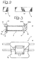
- Figure 2 includes two parts designated a) and b), respectively, representing front and the side views of the core of the choke of Figure 1,
- Figure 3, again including the two parts designated a) and b), respectively, are a longitudinally sectional view and end view of the bobbin of the choke of Figure 1, and
- Figure 4 is exemplary of a typical mounting arrangement of the choke of Figure 1 on a printed circuit board (PCB).
- In Figures 1 and 4 of the annexed drawing, reference numeral 1 designates as a whole a rod core chore for use e.g. as a lamp choke included in an electronic ballast of a fluorescent lamp (not shown).
- The lamp choke 1 is essentially comprised of a copper wire winding 2 wound around a
plastic bobbin 3 having aferrite core 4 inserted therein, so that the bobbin 3 (and the winding 2) surround thecore 4. - As better shown in Figure 2, the
core 4 is typically in the form of a small rod of a ferrite having long and narrow solid shape. - Accoring to a preferred embodiment of the invention, said solid is in form of a parallelepipid.
- Typically, the
core 4 is of almost rectangular cross-section (dimensions of 3 x 3.5 millimetres being a typical case in point) with a length in the range of 14 millimetres. Of course, those quantitative data are purely exemplary and must not be construed in a limiting sense of the scope of the invention. - Modification may be made by those skilled in the art without departing from the ambit of the invention. One of these modifications is to implement the
core 4 in form of a long and narrow solid having cilidrical shape, if not severe requiremenets are required in terms of space taken on the printed circuit board. - As best appreciated in the views of Figure 3, the
bobbin 3 is essentially comprised of an approximately tubular body of a plastic material (such as PBT) of a general beaker-type shape. Stated otherwise, thebobbin 3 is preferably in the form of a tubular body with a rectangular, viz. almost square cross-sectional shape. The tubular body of thebobbin 3 is fully or partly closed at oneend 3a and open at theopposite end 3b. In that way, thecore 4 can be inserted into thebobbin 3 by longitudinal sliding thecore 4 into thebobbin 3 starting from theopen end 3b until the end of thecore 4 first inserted into the bobbin abuts against theclosed end 3a. - After the core insertion, a
small plastics nose 30 at theopen end 3b of thebobbin 3 securely retains thecore 4 within thebobbin 3 by preventing any relative longitudinal movement of the bobbin (and the winding 2 wound therearound) and thecore 4. Thecore 4 is longitudinally confined between theclosed end 3a of thebobbin 3 and thenose 30. Typically, the nose is heat-deformed to engage the opposite end of thecore 4. - This arrangement is advantageous in order to avoid any noisy mechanic resonance frequency during choke operation and any variations in the choke inductance due to different possible relative positioning of the
ferrite core 4 and the winding 2 wound around thebobbin 3. - By way of general reference, in the case of chokes 1 corresponding to the arrangement described herein and including 465 turns and 530 turns (corresponding to inductance values of 2.7mH and 3.3mH, respectively) it has been found that a 1% (one percent) variation in the number of turns leads to variations in the inductance value in the range of about 2% (two percent). Such a turn number variation is reasonably sufficient to compensate for any variations in the mechanic/magnetic parameters of the choke.
- This feature appears to be advantageous, in direct comparison with manufacturing conventional chokes having closed magnetic circuits with E-shaped cores (so-called E-chokes), in that it enables to dispense with any adjusting airgap core system in the production process as normally used in order to achieve the desired the inductance value in choke production lines. This significantly contributes to simplicity and to cost reduction.
-
Reference numerals 31 in Figure 3 designate two flanges (or sets of flange formations) provided at the ends of the tubular body of thebobbin 3. These flanges act as lateral confinement walls or stops for the two ends of the winding 2, thus preventing any undesired longitudinal relative sliding of the winding 2 and thebobbin 3. - As is well known, the reciprocal positioning of the core and the winding greatly influences the inductance value of a choke and its current saturation level, the best magnetic coupling between the core and the winding being obtained when total longitudinal superposition is achieved. A slight relative axial shift between the core and the winding reduces such coupling and the inductance as well as the current saturation level.
- The arrangement described herein ensures precise location and positioning of the
core 4 within the bobbin 3 (via the end confinement formations represented by theclosed end 3a and the tooth formation 30) while also ensuring that, once inserted into thebobbin 3, thecore 4 retains a well defined axial position to thebobbin 3. - The end flanges of 31 of the
bobbin 3 in turn ensure proper axial positioning of the winding 2 with respect to thebobbin 3 and thus with respect to thecore 4 by also ensuring that this proper axial positioning is maintained over time. This while also preventing the winding wire from coming into contact with any sharp edges as possibly present in theferrite core 4. Any scratching of the wire insulation by the ferrite is thus securely avoided. - An
extension 32, typically in the form of additional flanges protruding from theflanges 31 in a plane orthogonal to the plane of theflanges 31 allow easy positioning of metal pins 33 provided at the ends of thebobbin 3. The possibility also exists of inserting a third pin 33a in a further support/extension 32a for an auxiliary winding (auto-transformer). Such metal pins act as connecting pins of the choke winding(s) to a printed circuit board (PCB) 5 as shown in Figure 4. Specifically, Figure 4 shows a choke 1 mounted on a PCB together with various other electronic components (collectively designated 6) usually included in an electronic ballast of e.g. fluorescent lamp. - The pin layout described allows easy pin insertion at one side of the printed
circuit board 5 and soldering thereof on the opposite side of the printedcircuit board 5. Moreover, such an arrangement leads to a low profile of the choke that can thus be mounted very close and with reduced "height" with respect to the PCB plane. - The arrangement shown allows asymmetric positioning of the two
pins 33, which also permits different pin-out versions to be developed depending on the side of thebobbin 3 which is desired to be used for pin insertion in the printed circuit ofboard 5. In fact, the arrangement shown makes it possible to solder the winding at one pin end while inserting the pin into the printed circuit board at the opposite end and vice versa. Additionally, such an asymmetric pin layout facilitates easy insertion of the ferrite core into thebobbin 3 without interference. In fact, in the currently prevailing arrangement, when assembled with the core, thebobbin 3 is already provided with the pins. - Chokes as shown herein have demonstrated improved thermal performance in comparison with prior art drum core chokes, which can be explained by a reduced AC resistance and larger thermal exchange surface.
- Of course, without prejudice to the underlying principle of the invention, the details and the embodiments may vary, also significantly, with respect to what has been described, by way of example only, without departing from the scope of the invention as defined by the annexed claims.
Claims (19)
- A rod core choke, including:- a core (4) in the form of a rod having a long and narrow solid shape,- a sheath (bobbin - 3) of an electrically insulating material surrounding said core (4), and- a wire winding (2) around the said sheath (3), whereby said sheath (3) mutually insulates said core (4) and said wire winding (2).
- The choke of claim 1, characterized in that said core (4) is in form of a rod having parallelepiped shape.
- The choke of claim 1, characterized in that said core (4) is in form of a rod having cylindrical shape.
- The choke of claim 2, characterized in that said core (4) has a rectangular cross section.
- The choke of claim 2, characterized in that said core (4) has a square cross section.
- The choke of claim 3 characterized in that said core (4) has an elliptic cross section.
- The choke of either of claims 1 or 2, or 3, characterized in that said sheath (3) includes axial containment formations (3a, 30) to retain said core (4) at a fixed axial position within said sheath (3).
- The choke of any of the previous claims, characterized in that said sheath (3) is in the form of substantially tubular body having a closed end (3a).
- The choke of claims 7 and 8, characterized in that said the closed end (3a) of the sheath (3) forms an abutment formation preventing axial displacement of said core (4) relative to said sheath (3) beyond the abutment condition against said closed end (3a).
- The choke of any of the previous claims, characterized in that said sheath (3) is in the form of substantially tubular body having a closed end (3a) and an open end (3b) opposite said closed end (3a), whereby said core (4) is slidably insertable into said sheath (3) via said open end (3b).
- The choke of claim 10, characterized in that said open end (3b) of said sheath (3) has an associated formation (30) to prevent axial displacement of said core (4) inserted in said sheath (3) out of said open end (3b) of said sheath (3).
- The choke of any of the previous claims, characterized in that said sheath (3) is provided with flange formations (31) forming longitudinal confinement end formations for said wire winding (2).
- The choke of any of the previous claims, characterized in that it includes end connection pins (33) of said wire winding (2) and said sheath (3) includes mounting formation (32; 32a) for supporting said connection pins (33; 33a).
- The choke of claim 13, characterized in that said mounting formation (32) allow said wire winding (2) to be soldered at either end of each of said pins.
- The choke of any of the previous claims, characterized in that said electrically insulating material includes a plastics material.
- The choke of claim 15, characterized in that said plastic material is PBT.
- The choke of any of the previous claims, characterized in that said core (4) is a ferrite core.
- A ballast for a fluorescent lamp including the choke of any of claims 1 to 17
- A method of manufacturing a rod core choke, the method including the steps of:- providing a core (4) in the form of a rod having long and narrow solid shape,- surrounding said core (4) with a sheath (bobbin 3) of an electrically insulating material, and- winding a wire (2) around said sheath (3), whereby said sheath (3) mutually insulates said core (4) and said wire (2) wound around said sheath (3).
Priority Applications (4)
| Application Number | Priority Date | Filing Date | Title |
|---|---|---|---|
| EP04425773A EP1648000B1 (en) | 2004-10-13 | 2004-10-13 | A rod core choke, an electronic ballast including the same and method of manufacturing |
| DE602004012751T DE602004012751T2 (en) | 2004-10-13 | 2004-10-13 | Rod-shaped core choke, ballast and method of manufacture |
| AT04425773T ATE390698T1 (en) | 2004-10-13 | 2004-10-13 | ROD-SHAPED CORE CHOKER, BALLAST AND METHOD FOR PRODUCTION |
| CN200510113573.6A CN1767092A (en) | 2004-10-13 | 2005-10-13 | Rod core choke coil, electronic ballast using same, and manufacturing method thereof |
Applications Claiming Priority (1)
| Application Number | Priority Date | Filing Date | Title |
|---|---|---|---|
| EP04425773A EP1648000B1 (en) | 2004-10-13 | 2004-10-13 | A rod core choke, an electronic ballast including the same and method of manufacturing |
Publications (2)
| Publication Number | Publication Date |
|---|---|
| EP1648000A1 true EP1648000A1 (en) | 2006-04-19 |
| EP1648000B1 EP1648000B1 (en) | 2008-03-26 |
Family
ID=34932825
Family Applications (1)
| Application Number | Title | Priority Date | Filing Date |
|---|---|---|---|
| EP04425773A Expired - Lifetime EP1648000B1 (en) | 2004-10-13 | 2004-10-13 | A rod core choke, an electronic ballast including the same and method of manufacturing |
Country Status (4)
| Country | Link |
|---|---|
| EP (1) | EP1648000B1 (en) |
| CN (1) | CN1767092A (en) |
| AT (1) | ATE390698T1 (en) |
| DE (1) | DE602004012751T2 (en) |
Cited By (1)
| Publication number | Priority date | Publication date | Assignee | Title |
|---|---|---|---|---|
| WO2023237958A1 (en) * | 2022-06-09 | 2023-12-14 | Dh Technologies Development Pte. Ltd. | Rf choke for use in a mass spectrometer and rf choke |
Citations (1)
| Publication number | Priority date | Publication date | Assignee | Title |
|---|---|---|---|---|
| US20020079999A1 (en) * | 2000-12-26 | 2002-06-27 | Abdel-Tawab Khaled I. | Coil and method for making same |
Family Cites Families (1)
| Publication number | Priority date | Publication date | Assignee | Title |
|---|---|---|---|---|
| DE3009578A1 (en) * | 1980-03-13 | 1981-09-24 | Vogt Gmbh & Co Kg, 8391 Erlau | METHOD FOR PRODUCING THROTTLE COILS OR THE LIKE WITH THICK WIRE THAT IS PROVIDED WITH A MAGNETICALLY CONDUCTING ROD CORE |
-
2004
- 2004-10-13 AT AT04425773T patent/ATE390698T1/en not_active IP Right Cessation
- 2004-10-13 EP EP04425773A patent/EP1648000B1/en not_active Expired - Lifetime
- 2004-10-13 DE DE602004012751T patent/DE602004012751T2/en not_active Expired - Lifetime
-
2005
- 2005-10-13 CN CN200510113573.6A patent/CN1767092A/en active Pending
Patent Citations (1)
| Publication number | Priority date | Publication date | Assignee | Title |
|---|---|---|---|---|
| US20020079999A1 (en) * | 2000-12-26 | 2002-06-27 | Abdel-Tawab Khaled I. | Coil and method for making same |
Cited By (1)
| Publication number | Priority date | Publication date | Assignee | Title |
|---|---|---|---|---|
| WO2023237958A1 (en) * | 2022-06-09 | 2023-12-14 | Dh Technologies Development Pte. Ltd. | Rf choke for use in a mass spectrometer and rf choke |
Also Published As
| Publication number | Publication date |
|---|---|
| CN1767092A (en) | 2006-05-03 |
| ATE390698T1 (en) | 2008-04-15 |
| DE602004012751D1 (en) | 2008-05-08 |
| EP1648000B1 (en) | 2008-03-26 |
| DE602004012751T2 (en) | 2009-05-14 |
Similar Documents
| Publication | Publication Date | Title |
|---|---|---|
| CN102449709B (en) | Surface mounting magnetic device | |
| US6262649B1 (en) | Power magnetic device employing a leadless connection to a printed circuit board and method of manufacture thereof | |
| US6927660B2 (en) | Coil device with edgewise winding | |
| US20120038448A1 (en) | Transformer and display device using the same | |
| JPH0564845B2 (en) | ||
| KR102273354B1 (en) | Electromagnetic induction apparatus and method of producing the same | |
| JP2000164431A (en) | Inductor | |
| USRE39453E1 (en) | Low profile inductive component | |
| EP1648000B1 (en) | A rod core choke, an electronic ballast including the same and method of manufacturing | |
| US7694407B2 (en) | Method for manufacturing a miniature surface-mount electronic component | |
| JP4761082B2 (en) | Horizontal coil parts | |
| JP2010093107A (en) | Lateral type coil component | |
| US6930582B2 (en) | Self lead foil winding configuration for transformers and inductors | |
| CN1623212A (en) | Former and coil for printed circuit board assembly | |
| JP2000509910A (en) | Low profile magnetic element having planar winding structure with reduced conductor loss | |
| US20150116069A1 (en) | Coil component and method of manufacturing the same | |
| JP5059050B2 (en) | Winding frame and winding parts | |
| KR101656013B1 (en) | Coil component | |
| JP4798551B2 (en) | Filter parts | |
| JP2000150258A (en) | Coil component using terminal holder separate from bobbin | |
| US6642830B1 (en) | Self lead foil winding configuration for transformers and inductors | |
| JPH1167553A (en) | Electronic component coils, inductors, and transformers | |
| KR100909397B1 (en) | Terminal structure of transformer bobbin for inverter | |
| JPH08306559A (en) | Coil part | |
| KR200398617Y1 (en) | A bobbin structure for transformer |
Legal Events
| Date | Code | Title | Description |
|---|---|---|---|
| PUAI | Public reference made under article 153(3) epc to a published international application that has entered the european phase |
Free format text: ORIGINAL CODE: 0009012 |
|
| AK | Designated contracting states |
Kind code of ref document: A1 Designated state(s): AT BE BG CH CY CZ DE DK EE ES FI FR GB GR HU IE IT LI LU MC NL PL PT RO SE SI SK TR |
|
| AX | Request for extension of the european patent |
Extension state: AL HR LT LV MK |
|
| 17P | Request for examination filed |
Effective date: 20061025 |
|
| AKX | Designation fees paid |
Designated state(s): AT BE BG CH CY CZ DE DK EE ES FI FR GB GR HU IE IT LI LU MC NL PL PT RO SE SI SK TR |
|
| 17Q | First examination report despatched |
Effective date: 20070509 |
|
| GRAP | Despatch of communication of intention to grant a patent |
Free format text: ORIGINAL CODE: EPIDOSNIGR1 |
|
| RTI1 | Title (correction) |
Free format text: A ROD CORE CHOKE, AN ELECTRONIC BALLAST INCLUDING THE SAME AND METHOD OF MANUFACTURING |
|
| GRAS | Grant fee paid |
Free format text: ORIGINAL CODE: EPIDOSNIGR3 |
|
| GRAA | (expected) grant |
Free format text: ORIGINAL CODE: 0009210 |
|
| AK | Designated contracting states |
Kind code of ref document: B1 Designated state(s): AT BE BG CH CY CZ DE DK EE ES FI FR GB GR HU IE IT LI LU MC NL PL PT RO SE SI SK TR |
|
| REG | Reference to a national code |
Ref country code: GB Ref legal event code: FG4D |
|
| REG | Reference to a national code |
Ref country code: IE Ref legal event code: FG4D Ref country code: CH Ref legal event code: EP |
|
| REF | Corresponds to: |
Ref document number: 602004012751 Country of ref document: DE Date of ref document: 20080508 Kind code of ref document: P |
|
| PG25 | Lapsed in a contracting state [announced via postgrant information from national office to epo] |
Ref country code: FI Free format text: LAPSE BECAUSE OF FAILURE TO SUBMIT A TRANSLATION OF THE DESCRIPTION OR TO PAY THE FEE WITHIN THE PRESCRIBED TIME-LIMIT Effective date: 20080326 |
|
| PG25 | Lapsed in a contracting state [announced via postgrant information from national office to epo] |
Ref country code: AT Free format text: LAPSE BECAUSE OF FAILURE TO SUBMIT A TRANSLATION OF THE DESCRIPTION OR TO PAY THE FEE WITHIN THE PRESCRIBED TIME-LIMIT Effective date: 20080326 |
|
| NLV1 | Nl: lapsed or annulled due to failure to fulfill the requirements of art. 29p and 29m of the patents act | ||
| PG25 | Lapsed in a contracting state [announced via postgrant information from national office to epo] |
Ref country code: BE Free format text: LAPSE BECAUSE OF FAILURE TO SUBMIT A TRANSLATION OF THE DESCRIPTION OR TO PAY THE FEE WITHIN THE PRESCRIBED TIME-LIMIT Effective date: 20080326 Ref country code: SI Free format text: LAPSE BECAUSE OF FAILURE TO SUBMIT A TRANSLATION OF THE DESCRIPTION OR TO PAY THE FEE WITHIN THE PRESCRIBED TIME-LIMIT Effective date: 20080326 Ref country code: PL Free format text: LAPSE BECAUSE OF FAILURE TO SUBMIT A TRANSLATION OF THE DESCRIPTION OR TO PAY THE FEE WITHIN THE PRESCRIBED TIME-LIMIT Effective date: 20080326 |
|
| PG25 | Lapsed in a contracting state [announced via postgrant information from national office to epo] |
Ref country code: CZ Free format text: LAPSE BECAUSE OF FAILURE TO SUBMIT A TRANSLATION OF THE DESCRIPTION OR TO PAY THE FEE WITHIN THE PRESCRIBED TIME-LIMIT Effective date: 20080326 Ref country code: SK Free format text: LAPSE BECAUSE OF FAILURE TO SUBMIT A TRANSLATION OF THE DESCRIPTION OR TO PAY THE FEE WITHIN THE PRESCRIBED TIME-LIMIT Effective date: 20080326 Ref country code: SE Free format text: LAPSE BECAUSE OF FAILURE TO SUBMIT A TRANSLATION OF THE DESCRIPTION OR TO PAY THE FEE WITHIN THE PRESCRIBED TIME-LIMIT Effective date: 20080626 Ref country code: PT Free format text: LAPSE BECAUSE OF FAILURE TO SUBMIT A TRANSLATION OF THE DESCRIPTION OR TO PAY THE FEE WITHIN THE PRESCRIBED TIME-LIMIT Effective date: 20080901 Ref country code: ES Free format text: LAPSE BECAUSE OF FAILURE TO SUBMIT A TRANSLATION OF THE DESCRIPTION OR TO PAY THE FEE WITHIN THE PRESCRIBED TIME-LIMIT Effective date: 20080707 |
|
| PG25 | Lapsed in a contracting state [announced via postgrant information from national office to epo] |
Ref country code: NL Free format text: LAPSE BECAUSE OF FAILURE TO SUBMIT A TRANSLATION OF THE DESCRIPTION OR TO PAY THE FEE WITHIN THE PRESCRIBED TIME-LIMIT Effective date: 20080326 Ref country code: RO Free format text: LAPSE BECAUSE OF FAILURE TO SUBMIT A TRANSLATION OF THE DESCRIPTION OR TO PAY THE FEE WITHIN THE PRESCRIBED TIME-LIMIT Effective date: 20080326 |
|
| ET | Fr: translation filed | ||
| PG25 | Lapsed in a contracting state [announced via postgrant information from national office to epo] |
Ref country code: DK Free format text: LAPSE BECAUSE OF FAILURE TO SUBMIT A TRANSLATION OF THE DESCRIPTION OR TO PAY THE FEE WITHIN THE PRESCRIBED TIME-LIMIT Effective date: 20080326 |
|
| PLBE | No opposition filed within time limit |
Free format text: ORIGINAL CODE: 0009261 |
|
| STAA | Information on the status of an ep patent application or granted ep patent |
Free format text: STATUS: NO OPPOSITION FILED WITHIN TIME LIMIT |
|
| 26N | No opposition filed |
Effective date: 20081230 |
|
| PG25 | Lapsed in a contracting state [announced via postgrant information from national office to epo] |
Ref country code: BG Free format text: LAPSE BECAUSE OF FAILURE TO SUBMIT A TRANSLATION OF THE DESCRIPTION OR TO PAY THE FEE WITHIN THE PRESCRIBED TIME-LIMIT Effective date: 20080626 Ref country code: EE Free format text: LAPSE BECAUSE OF FAILURE TO SUBMIT A TRANSLATION OF THE DESCRIPTION OR TO PAY THE FEE WITHIN THE PRESCRIBED TIME-LIMIT Effective date: 20080326 |
|
| PG25 | Lapsed in a contracting state [announced via postgrant information from national office to epo] |
Ref country code: MC Free format text: LAPSE BECAUSE OF NON-PAYMENT OF DUE FEES Effective date: 20081031 |
|
| REG | Reference to a national code |
Ref country code: CH Ref legal event code: PL |
|
| PG25 | Lapsed in a contracting state [announced via postgrant information from national office to epo] |
Ref country code: CY Free format text: LAPSE BECAUSE OF FAILURE TO SUBMIT A TRANSLATION OF THE DESCRIPTION OR TO PAY THE FEE WITHIN THE PRESCRIBED TIME-LIMIT Effective date: 20080326 |
|
| PG25 | Lapsed in a contracting state [announced via postgrant information from national office to epo] |
Ref country code: CH Free format text: LAPSE BECAUSE OF NON-PAYMENT OF DUE FEES Effective date: 20081031 Ref country code: LI Free format text: LAPSE BECAUSE OF NON-PAYMENT OF DUE FEES Effective date: 20081031 Ref country code: IE Free format text: LAPSE BECAUSE OF NON-PAYMENT OF DUE FEES Effective date: 20081013 |
|
| PG25 | Lapsed in a contracting state [announced via postgrant information from national office to epo] |
Ref country code: HU Free format text: LAPSE BECAUSE OF FAILURE TO SUBMIT A TRANSLATION OF THE DESCRIPTION OR TO PAY THE FEE WITHIN THE PRESCRIBED TIME-LIMIT Effective date: 20080927 Ref country code: LU Free format text: LAPSE BECAUSE OF NON-PAYMENT OF DUE FEES Effective date: 20081013 |
|
| PG25 | Lapsed in a contracting state [announced via postgrant information from national office to epo] |
Ref country code: TR Free format text: LAPSE BECAUSE OF FAILURE TO SUBMIT A TRANSLATION OF THE DESCRIPTION OR TO PAY THE FEE WITHIN THE PRESCRIBED TIME-LIMIT Effective date: 20080326 |
|
| PG25 | Lapsed in a contracting state [announced via postgrant information from national office to epo] |
Ref country code: GR Free format text: LAPSE BECAUSE OF FAILURE TO SUBMIT A TRANSLATION OF THE DESCRIPTION OR TO PAY THE FEE WITHIN THE PRESCRIBED TIME-LIMIT Effective date: 20080627 |
|
| REG | Reference to a national code |
Ref country code: DE Ref legal event code: R081 Ref document number: 602004012751 Country of ref document: DE Owner name: OSRAM GMBH, DE Free format text: FORMER OWNER: OSRAM GESELLSCHAFT MIT BESCHRAENKTER HAFTUNG, 81543 MUENCHEN, DE Effective date: 20111214 |
|
| PGFP | Annual fee paid to national office [announced via postgrant information from national office to epo] |
Ref country code: FR Payment date: 20121031 Year of fee payment: 9 Ref country code: DE Payment date: 20121023 Year of fee payment: 9 |
|
| PGFP | Annual fee paid to national office [announced via postgrant information from national office to epo] |
Ref country code: IT Payment date: 20121024 Year of fee payment: 9 Ref country code: GB Payment date: 20121019 Year of fee payment: 9 |
|
| REG | Reference to a national code |
Ref country code: DE Ref legal event code: R081 Ref document number: 602004012751 Country of ref document: DE Owner name: OSRAM GMBH, DE Free format text: FORMER OWNER: OSRAM AG, 81543 MUENCHEN, DE Effective date: 20130205 |
|
| REG | Reference to a national code |
Ref country code: DE Ref legal event code: R081 Ref document number: 602004012751 Country of ref document: DE Owner name: OSRAM GMBH, DE Free format text: FORMER OWNER: OSRAM GMBH, 81543 MUENCHEN, DE Effective date: 20130823 |
|
| GBPC | Gb: european patent ceased through non-payment of renewal fee |
Effective date: 20131013 |
|
| PG25 | Lapsed in a contracting state [announced via postgrant information from national office to epo] |
Ref country code: GB Free format text: LAPSE BECAUSE OF NON-PAYMENT OF DUE FEES Effective date: 20131013 |
|
| REG | Reference to a national code |
Ref country code: DE Ref legal event code: R119 Ref document number: 602004012751 Country of ref document: DE Effective date: 20140501 |
|
| REG | Reference to a national code |
Ref country code: FR Ref legal event code: ST Effective date: 20140630 |
|
| PG25 | Lapsed in a contracting state [announced via postgrant information from national office to epo] |
Ref country code: DE Free format text: LAPSE BECAUSE OF NON-PAYMENT OF DUE FEES Effective date: 20140501 Ref country code: FR Free format text: LAPSE BECAUSE OF NON-PAYMENT OF DUE FEES Effective date: 20131031 Ref country code: IT Free format text: LAPSE BECAUSE OF NON-PAYMENT OF DUE FEES Effective date: 20131013 |