EP1647925A1 - Künstliche oder bionische Struktur mit modularen elektronischen Elementen zur Erzeugen oder Wiedererzeugen von korrekter Kommunikation zwischen Komponenten einer biologischen Struktur, insbesondere eines neuronalen Systems - Google Patents
Künstliche oder bionische Struktur mit modularen elektronischen Elementen zur Erzeugen oder Wiedererzeugen von korrekter Kommunikation zwischen Komponenten einer biologischen Struktur, insbesondere eines neuronalen Systems Download PDFInfo
- Publication number
- EP1647925A1 EP1647925A1 EP04425780A EP04425780A EP1647925A1 EP 1647925 A1 EP1647925 A1 EP 1647925A1 EP 04425780 A EP04425780 A EP 04425780A EP 04425780 A EP04425780 A EP 04425780A EP 1647925 A1 EP1647925 A1 EP 1647925A1
- Authority
- EP
- European Patent Office
- Prior art keywords
- neural structure
- structure according
- artificial neural
- bionic
- modular electronic
- Prior art date
- Legal status (The legal status is an assumption and is not a legal conclusion. Google has not performed a legal analysis and makes no representation as to the accuracy of the status listed.)
- Withdrawn
Links
Images


Classifications
-
- G—PHYSICS
- G06—COMPUTING OR CALCULATING; COUNTING
- G06N—COMPUTING ARRANGEMENTS BASED ON SPECIFIC COMPUTATIONAL MODELS
- G06N3/00—Computing arrangements based on biological models
- G06N3/02—Neural networks
- G06N3/06—Physical realisation, i.e. hardware implementation of neural networks, neurons or parts of neurons
- G06N3/061—Physical realisation, i.e. hardware implementation of neural networks, neurons or parts of neurons using biological neurons, e.g. biological neurons connected to an integrated circuit
Definitions
- the present invention refers to an artificial or bionic neural structure formed by modular electronic elements for generating and/or re-establishing correct communication between components of a biological structure, in particular a nervous system.
- the invention refers to a structure of the aforementioned type and comprising a central section responsible for the generation of electrical signals, as well as a first and a second end section connected to the central section and to respective input and output terminals located on opposite sides with respect to a point of interruption of the communication.
- the invention concerns a system for producing electrical signals to be used in the field of bionics in human and animal nervous systems that have suffered damage to the mechanisms for transmitting information after illness and/or traumatic events; the following description is made with reference to this field of application with the sole purpose of simplifying its presentation.
- neurotransmitters that are molecules capable of transmitting information signals at the cellular synapses according to an electro-chemical mechanism.
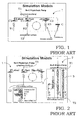
- Such an Na-K physiologic pump can be emulated electronically through a model schematically illustrated in figure 1 and wholly indicated with 1.
- Such a model which we shall define as physiologic, essentially comprises three modelling branches formed from series (or parallel) RC (or RLC) circuits, connected together in parallel between a first T1 and a second terminal T2, respectively corresponding to the surface of a cytoplasm and to an extracellular surface.
- serial (or parallel) RC (or RLC) circuits R1-C1, R2-C2 and R3-C3 are used to model the equilibriums of the elements Cl, K and Na, respectively.
- the voltage originating from the direct current (DC) generators C1, C2 and C3 is fixed at -69mV, -75mV and +55mV, respectively.
- a common capacitor C is also foreseen, connected in parallel to the RC (or RLC) circuits between the terminals T1 and T2.
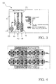
- a corresponding simplified model of the Na-K pump which we shall define as bionic, is illustrated as an example in figure 3 and wholly indicated with 2.
- Such a bionic model 2 comprises, in an analogous way to the physiologic model 1, a first T1 and a second terminal T2, respectively corresponding to the surface of a cytoplasm and to the extracellular surface between which a first 3, a second 4 and a third modelling branch 5 are connected.
- the first modelling branch 3 comprises, in series between the terminals T1 and T2 respectively, a DC generator, a first resistor, an inverter switch and a second resistor, an intermediate point of the inverter switch being connected to the second terminal T2 through a further capacitor.
- the second branch 4 comprises, in series between the terminals T1 and T2 respectively, a DC generator, a first switch, a first RL circuit, a second switch and a second RL circuit.
- the third branch 5 comprises, again in series between the terminals T1 and T2 respectively, a DC generator, a first switch, a first RLC circuit, a second switch and a second RLC circuit.
- a possible interruption in this communication may also be due to structural defects of a given cell or of a group of cells and can produce a lack of communication of the information in question.
- the group of cells involved by such a lack or interruption in communication does not therefore accomplish its natural task.
- the technical problem forming the basis of the present invention is that of devising a device or a modular electronic element having structural and functional characteristics such as to allow an artificial neural structure to be made that is capable of simulating a group of natural neurones in situ.
- the solution idea forming the basis of the present invention is that of making an artificial neural structure through a plurality of swinging circuits grouped in meshes.
- the invention proposes collecting together and processing analogue and digital signals produced inside such meshes so as to provide compressed information bands.
- the neurotransmitters move along predetermined directions and at a constant frequency or isofrequency.
- the bionic model 10 comprises, in accordance with the well known physiologic model 1 illustrated previously, a first terminal T1 and a second terminal T2, respectively corresponding to the surface of a cytoplasm and to the extracellular surface between which a first 11, a second 12 and a third modelling branch 13 are connected.
- the first modelling branch 11 comprises, in series between the terminals T1 and T2 respectively, a DC generator, a first resistor, an inverter switch and a second resistor, an intermediate point of the inverter switch being connected to the second terminal T2 also through a capacitor.
- the first modelling branch 11 also comprises, connected between the second resistor and the second terminal T2, a capacitor circuit 14 with a complex structure and comprising a variable number of elementary capacitor structures.
- the second branch 12 comprises, in series between the terminals T1 and T2 respectively, a DC generator, a switch and an RL circuit.
- the second modelling branch 12 also comprises, connected between the RL circuit and the second terminal T2, a first complex swinging circuit 15 in turn comprising a variable number of elementary swinging circuits formed from switches and RL circuits.
- the third branch 13 comprises, again in series between the terminals T1 and T2 respectively, a DC generator, a switch and an RLC circuit.
- the third modelling branch 13 also comprises, connected between the RLC circuit and the second terminal T2, a second complex swinging circuit 16 in turn comprising a variable number of elementary swinging circuits formed from switches and RLC circuits.
- the elementary swinging circuits can be series circuits, as illustrated as an example in figure 3, but, in a totally equivalent way, they can be parallel circuits or mixed series-parallel circuits.
- the complex swinging circuits 15 and 16 substantially comprise elementary components such as resistors, inductors and capacitors, organised in meshes or networks, such meshes being able to be increased in number as illustrated in figure 4.
- the bionic model 10 Starting from known equilibrium values of the Na-K pump, the bionic model 10 according to the invention allows an artificial or bionic neural structure to be obtained.
- the proposed bionic neural structure is made to work in a substantially forced way, artificially causing its imbalance.
- the proposed bionic neural structure comprises a plurality of modular cards, connected together, suitable for producing analogue electrical information signals with various waveforms and various electrical powers.
- such a bionic neural structure acts with frequencies operating in the field of radio waves and in the field of light waves.
- the electrical powers used for the generation and subsequent treatment of signals are bio-compatible or computer-compatible, according to the following ways:
- a bionic neural structure 20 comprises a central section 21 responsible for the generation of signals for transmission, as well as a first 22A and a second end section 22B connected to the central section 21 and to a respective input terminal IN and output terminal OUT of the bionic neural structure 20.
- the first end section 22A is suitable for collecting control signals received on the input terminal IN and for sending them to the central station
- the second end section 22B is suitable for routing and amplifying the signals for the transmission coming from the central section 21 towards the output terminal OUT.
- the bionic neural structure 20 allows the connection between a first 23A and a second group of biological neurones 23B, in particular at a first and a second intersynaptic space 24A and 24B, respectively.
- the bionic neural structure 20 is also equipped with an input interface 25A, connected between the first intersynaptic space 24A and the input terminal IN, and with an output interface 25B, connected between the output terminal OUT and the second intersynaptic space 24B.
- the input interface 25A comprises a set of contact probes suitable for receiving suitable neuro-electric signals from the first intersynaptic space 24A and connected to control and feedback elements.
- the output interface 25B comprises a set of contact probes suitable for transmitting suitable neuro-electric signals to the second intersynaptic space 24B and connected to control and feedback elements.
- connection probes, in reception and in transmission, contained in the input and output interfaces 25A and 25B, respectively, are similar and/or analogous to those now conventionally used for brain stereotaxic neuro-surgery.
- bionic neural structure 20 for connection to a first and second group of integrated circuits 26A and 26B, respectively, replacing the contact probes inside the input and output interfaces with suitable connection terminals, as schematically illustrated in figure 6.
- connection terminals, in reception and in transmission, contained in the input and output interfaces 25A and 25B, respectively, are similar and/or analogous to the usual ones between wired circuits and/or integrated circuits.
- the proposed bionic neural structure 20 is, indeed, able to work in at least two ways of operating and therefore in at least two separate fields of application:
- the bionic neural structure 20 operates receiving and transmitting analogue signals, which, by their nature, provide all possible information and are the only things that are bio-compatible, avoiding transductions and/or conversions.
- the bionic neural structure 20 comprises a plurality of elementary components, or bionic modules, based upon the bionic model 10 of the Na-K pump illustrated in figure 3.
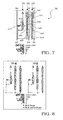
- each module 30, as schematically indicated in figure 7, comprises a first, a second and a third circuit branch 31, 32 and 33, respectively, corresponding to the modelling branches illustrated with reference to the bionic module 10, the number h of which can vary (with h>3).
- the first circuit branch 31 has a first and a second internal circuit node X11 and X21, respectively, at the ends of a capacitor included in it.
- the second circuit branch 32 has a first and a second internal circuit node X21 and X22, respectively, at the ends of a first RL circuit included in it, a third and a fourth internal circuit node X23 and X24, respectively, at the ends of a second RL circuit included in it.
- the third circuit branch 33 has a first and a second internal circuit node X31 and X32, respectively, at the ends of a first RLC circuit included in it, a third and a fourth internal circuit node X33 and X34, respectively, at the ends of a second RLC circuit included in it.
- corresponding counter-signals were obtained by simply inverting the power supplies of the circuit branches 31-33, as schematically illustrated in figure 8 where a module 30A suitable for making an Na-K pump and a module 30B suitable for making an Na-K inverse pump are compared.
- the module 30 is suitably connected to a logic processing structure 31 comprising a plurality of logic gates suitable for receiving signals S1-S5 inside the module 30 in an alternating manner, so as to provide information bands on a plurality of output terminals OUTn, as schematically illustrated in figure 9.
- the plurality of logic gates inside the logic processing structure 31, similar or analogous to digital NOT, AND, OR gates, is organised in groups, according to known configurations in series and/or in parallel.
- each initial signal S1-S5 produced inside the module 30 is treated by the groups of logic gates to obtain elementary information bands (again analogue electric information signals) responding to the conditions dictated by a conventional logic (of the binary 0.1 type) and/or by "Fuzzy" logic, to then be recomposed in the output information bands.
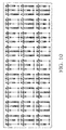
- Each module 30 can comprise twenty-seven configurations that can also coexist, as schematically illustrated in figure 10, given by the combinations of the base distribution; in particular, these theoretically correspond to twenty-seven biochemical mechanisms that are similar or analogous, causing, in simulation, the analogue of twenty-seven resonance hybrids.
- the modular cards 50 are organised into:
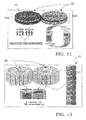
- the two sub-assemblies constitute an overall assembly capable of generating the signals required for the bionic neural structure 20, in the illustrated example using 128 cards that make a base assembly 60 as schematically illustrated in figure 12.
- Each new band of information signals is divided into various bands of sub-signals with suitable retro-actuated phasing, which, in turn, are distributed, for example, between the modular cards, with the mathematical criteria of the Setting, Combination and Permutation operations, obtaining composite bands.
- Each composite band can, in turn, be amplified (through groups of circuits with two or more meshes, similar to the previous ones and replaced in their functions by modules or blocks, for example of the AGC and/or PGA type) and, subsequently prepared for transmission with final controls carried out through further groups of circuits with two or more meshes, also similar to the previous ones and replaced in their functions by modules or blocks, for example of the AGC and/or PGA type, thus obtaining the definitive signals.
- Each definitive signal, ready for analogue transmission, can also be subjected to Analogue/Digital converters to obtain possible immediate computerised controls.
- the signals transmitted are also retro-actuated up to the switches of the individual branches of the individual meshes of the individual electrical schemes, to carry out both new ways of producing the initial signals (waveform, wavelength, electrical power), and the formation of growing memories (for example of the E 2 type) that are also subjected to possible computerised controls.
- the switches contained in the modules 30 are also able (through suitable frequency adapters, waveform adapters, etc.) to receive signals from other transmission sources, signals that in turn regulate the production of the signals to be transmitted both in waveform, in wavelength and in electrical power.
- the analogue signals going in are directed to frequency and waveform converters of the swings of the elementary circuits included in the bionic neural structure 20, provided comparing with the memories of the generation circuits themselves.
- the analogue signals in output are sent to double probes one of which is in feedback for comparing with the memories of the generation circuits.
- the digital signals going in are firstly subjected to Digital/Analogue converters and then directed to the frequency and waveform converters of the swings of the circuits, provided comparing with the memories of the generation circuits.
- the analogue signals in output are firstly subjected to Digital/Analogue converters and then sent to double connections one of which is in feedback for comparing, after the obvious Digital/Analogue conversion, with the memories of the generation circuits.
- bionic neural structure 20 allows an instrument operating exclusively with (direct or indirect) analogue inputs and outputs, whilst still being totally compatible with possible digital commands, to be made.
- the bionic neural structure 20 makes it possible to make:
- the bionic neural structure 20 makes it possible to make:
- the bionic neural structure 20 makes it possible to make, for example, an interconnection system between the biological and the artificial, for tele-monitoring and/or sanitary tele-tests and/or other.
- the proposed bionic neural structure 20 has a structural configuration such as to be able to be transformed, for example using the methods of nanotechnology, into structures, for example fullerenic and/or of nano-tubes and/or other.
- the proposed bionic neural structure 20 is not only self-organising, but continually refers to itself, basically behaving like a autopoietic system, i.e. based upon the processes and upon their mutual relations and on the feedback between them.
- the hardware structure of the bionic neural structure 20 does not require any software programme, by itself carrying out an operating programme in a virtual, autonomous, dynamic and automatic way.
- the proposed bionic neural structure 20 transmits and processes analogue signals, in other words bio-compatible signals.
Landscapes
- Engineering & Computer Science (AREA)
- Physics & Mathematics (AREA)
- Health & Medical Sciences (AREA)
- Life Sciences & Earth Sciences (AREA)
- Biomedical Technology (AREA)
- Biophysics (AREA)
- Theoretical Computer Science (AREA)
- Molecular Biology (AREA)
- Neurology (AREA)
- Computational Linguistics (AREA)
- Artificial Intelligence (AREA)
- Data Mining & Analysis (AREA)
- Evolutionary Computation (AREA)
- General Health & Medical Sciences (AREA)
- Computing Systems (AREA)
- General Engineering & Computer Science (AREA)
- General Physics & Mathematics (AREA)
- Mathematical Physics (AREA)
- Software Systems (AREA)
- Microelectronics & Electronic Packaging (AREA)
- Measurement And Recording Of Electrical Phenomena And Electrical Characteristics Of The Living Body (AREA)
Priority Applications (1)
| Application Number | Priority Date | Filing Date | Title |
|---|---|---|---|
| EP04425780A EP1647925A1 (de) | 2004-10-15 | 2004-10-15 | Künstliche oder bionische Struktur mit modularen elektronischen Elementen zur Erzeugen oder Wiedererzeugen von korrekter Kommunikation zwischen Komponenten einer biologischen Struktur, insbesondere eines neuronalen Systems |
Applications Claiming Priority (1)
| Application Number | Priority Date | Filing Date | Title |
|---|---|---|---|
| EP04425780A EP1647925A1 (de) | 2004-10-15 | 2004-10-15 | Künstliche oder bionische Struktur mit modularen elektronischen Elementen zur Erzeugen oder Wiedererzeugen von korrekter Kommunikation zwischen Komponenten einer biologischen Struktur, insbesondere eines neuronalen Systems |
Publications (1)
| Publication Number | Publication Date |
|---|---|
| EP1647925A1 true EP1647925A1 (de) | 2006-04-19 |
Family
ID=34932831
Family Applications (1)
| Application Number | Title | Priority Date | Filing Date |
|---|---|---|---|
| EP04425780A Withdrawn EP1647925A1 (de) | 2004-10-15 | 2004-10-15 | Künstliche oder bionische Struktur mit modularen elektronischen Elementen zur Erzeugen oder Wiedererzeugen von korrekter Kommunikation zwischen Komponenten einer biologischen Struktur, insbesondere eines neuronalen Systems |
Country Status (1)
| Country | Link |
|---|---|
| EP (1) | EP1647925A1 (de) |
Cited By (1)
| Publication number | Priority date | Publication date | Assignee | Title |
|---|---|---|---|---|
| CN109714119A (zh) * | 2018-12-29 | 2019-05-03 | 中国人民解放军陆军工程大学 | 神经形态电路和信号频移检测系统 |
Citations (1)
| Publication number | Priority date | Publication date | Assignee | Title |
|---|---|---|---|---|
| WO2001060445A2 (en) * | 2000-02-17 | 2001-08-23 | Neurodan A/S | Methods and implantable systems for neural sensing and nerve stimulation |
-
2004
- 2004-10-15 EP EP04425780A patent/EP1647925A1/de not_active Withdrawn
Patent Citations (1)
| Publication number | Priority date | Publication date | Assignee | Title |
|---|---|---|---|---|
| WO2001060445A2 (en) * | 2000-02-17 | 2001-08-23 | Neurodan A/S | Methods and implantable systems for neural sensing and nerve stimulation |
Non-Patent Citations (4)
| Title |
|---|
| BERGER T W ET AL: "Brain-implantable biomimetic electronics as the next era in neural prosthetics", PROCEEDINGS OF THE IEEE IEEE USA, vol. 89, no. 7, 7 July 2001 (2001-07-07), pages 993 - 1012, XP002323298, ISSN: 0018-9219 * |
| ECKMILLER R: "BIOLOGY-INSPIRED PULSE PROCESSING NEURAL NETWORKS (BPN) FOR NEUROTECHNOLOGY", PROCEEDINGS OF THE INTERNATIONAL CONFERENCE ON ARTIFICIAL NEURAL NETWORKS, XX, XX, vol. 2, no. 3/4, May 1994 (1994-05-01), pages 1329 - 1334, XP002071156 * |
| ERRIGO D P: "CEREBRAL SIMULATION", NEUROMODULATION, BLACKWELL SCIENCE, MALDEN, MA, US, vol. 6, no. 3, July 2003 (2003-07-01), pages 204 - 206, XP008044392, ISSN: 1094-7159 * |
| JENKNER M ET AL: "Interfacing a silicon chip to pairs of snail neurons connected by electrical synapses", BIOLOGICAL CYBERNETICS SPRINGER-VERLAG GERMANY, vol. 84, no. 4, 2001, pages 239 - 249, XP002323299, ISSN: 0340-1200 * |
Cited By (2)
| Publication number | Priority date | Publication date | Assignee | Title |
|---|---|---|---|---|
| CN109714119A (zh) * | 2018-12-29 | 2019-05-03 | 中国人民解放军陆军工程大学 | 神经形态电路和信号频移检测系统 |
| CN109714119B (zh) * | 2018-12-29 | 2023-10-24 | 中国人民解放军陆军工程大学 | 神经形态电路和信号频移检测系统 |
Similar Documents
| Publication | Publication Date | Title |
|---|---|---|
| Karrer et al. | A practical guide to methodological considerations in the controllability of structural brain networks | |
| Lee et al. | An implantable wireless bidirectional communication microstimulator for neuromuscular stimulation | |
| Wang et al. | A dual band wireless power and data telemetry for retinal prosthesis | |
| EP2629846B1 (de) | Telemetrieoptimierung bei einem implantierbaren medizinproduktesystem zur erzeugung gleicher und maximaler abstände bei bidirektionalen kommunikationen | |
| CN112675428B (zh) | 抗癫痫电刺激硬件在环仿真系统 | |
| Ha et al. | A fully integrated RF-powered energy-replenishing current-controlled stimulator | |
| CN218607734U (zh) | 脉冲发生器及其电路系统、刺激器、医疗系统 | |
| EP1647925A1 (de) | Künstliche oder bionische Struktur mit modularen elektronischen Elementen zur Erzeugen oder Wiedererzeugen von korrekter Kommunikation zwischen Komponenten einer biologischen Struktur, insbesondere eines neuronalen Systems | |
| Kolbl et al. | IC-based neuro-stimulation environment for arbitrary waveform generation | |
| KR100994451B1 (ko) | 연산 기능을 갖는 가변부성저항으로 이루어진 생체 모방신경 세포 회로 | |
| Zhang et al. | Simulating the motion of a mechanical arm driven by neural circuit | |
| Eckmiller et al. | Exploration of a dialog-based tunable retina encoder for retina implants | |
| RU88812U1 (ru) | Комплекс имитации нагрузки для испытаний систем электропитания космических аппаратов | |
| Nazari et al. | A novel digital circuit for astrocyte-inspired stimulator to desynchronize two coupled oscillators | |
| Hasanuzzaman et al. | Capacitive-data links, energy-efficient and high-voltage compliant visual intracortical microstimulation system | |
| Remi et al. | Controlling phase synchrony in the mean field coupled Hindmarsh–Rose neurons | |
| CN118253038A (zh) | 一种结合脑电的闭环电刺激方法 | |
| Blanchard et al. | Snake robot controlled by biomimetic CPGs | |
| Besrour et al. | Quantized spiking neural networks on fpga: An application to retinal prosthetics | |
| Yao et al. | Response mechanism of the auditory FitzHugh–Nagumo neuron | |
| Si et al. | Inter-areal transmission of multiple neural signals through frequency-division-multiplexing communication | |
| Alam | An easy-to-build transcutaneous electrical stimulator for spinal cord stimulation therapy | |
| Jenderny et al. | Wave digital emulation of a light-modulated central pattern generator | |
| Chestek et al. | Microcontroller-based wireless recording unit for neurodynamic studies in saltwater | |
| Sawan et al. | A wireless implantable electrical stimulator based on two FPGAs |
Legal Events
| Date | Code | Title | Description |
|---|---|---|---|
| PUAI | Public reference made under article 153(3) epc to a published international application that has entered the european phase |
Free format text: ORIGINAL CODE: 0009012 |
|
| AK | Designated contracting states |
Kind code of ref document: A1 Designated state(s): AT BE BG CH CY CZ DE DK EE ES FI FR GB GR HU IE IT LI LU MC NL PL PT RO SE SI SK TR |
|
| AX | Request for extension of the european patent |
Extension state: AL HR LT LV MK |
|
| AKX | Designation fees paid | ||
| REG | Reference to a national code |
Ref country code: DE Ref legal event code: 8566 |
|
| STAA | Information on the status of an ep patent application or granted ep patent |
Free format text: STATUS: THE APPLICATION IS DEEMED TO BE WITHDRAWN |
|
| 18D | Application deemed to be withdrawn |
Effective date: 20061020 |