EP1647809A2 - Induction type displacement detector - Google Patents
Induction type displacement detector Download PDFInfo
- Publication number
- EP1647809A2 EP1647809A2 EP05022286A EP05022286A EP1647809A2 EP 1647809 A2 EP1647809 A2 EP 1647809A2 EP 05022286 A EP05022286 A EP 05022286A EP 05022286 A EP05022286 A EP 05022286A EP 1647809 A2 EP1647809 A2 EP 1647809A2
- Authority
- EP
- European Patent Office
- Prior art keywords
- receiving
- measurement axis
- flux coupling
- winding
- induction type
- Prior art date
- Legal status (The legal status is an assumption and is not a legal conclusion. Google has not performed a legal analysis and makes no representation as to the accuracy of the status listed.)
- Granted
Links
Images





Classifications
-
- G—PHYSICS
- G01—MEASURING; TESTING
- G01D—MEASURING NOT SPECIALLY ADAPTED FOR A SPECIFIC VARIABLE; ARRANGEMENTS FOR MEASURING TWO OR MORE VARIABLES NOT COVERED IN A SINGLE OTHER SUBCLASS; TARIFF METERING APPARATUS; MEASURING OR TESTING NOT OTHERWISE PROVIDED FOR
- G01D5/00—Mechanical means for transferring the output of a sensing member; Means for converting the output of a sensing member to another variable where the form or nature of the sensing member does not constrain the means for converting; Transducers not specially adapted for a specific variable
- G01D5/12—Mechanical means for transferring the output of a sensing member; Means for converting the output of a sensing member to another variable where the form or nature of the sensing member does not constrain the means for converting; Transducers not specially adapted for a specific variable using electric or magnetic means
- G01D5/14—Mechanical means for transferring the output of a sensing member; Means for converting the output of a sensing member to another variable where the form or nature of the sensing member does not constrain the means for converting; Transducers not specially adapted for a specific variable using electric or magnetic means influencing the magnitude of a current or voltage
- G01D5/20—Mechanical means for transferring the output of a sensing member; Means for converting the output of a sensing member to another variable where the form or nature of the sensing member does not constrain the means for converting; Transducers not specially adapted for a specific variable using electric or magnetic means influencing the magnitude of a current or voltage by varying inductance, e.g. by a movable armature
- G01D5/204—Mechanical means for transferring the output of a sensing member; Means for converting the output of a sensing member to another variable where the form or nature of the sensing member does not constrain the means for converting; Transducers not specially adapted for a specific variable using electric or magnetic means influencing the magnitude of a current or voltage by varying inductance, e.g. by a movable armature by influencing the mutual induction between two or more coils
- G01D5/2053—Mechanical means for transferring the output of a sensing member; Means for converting the output of a sensing member to another variable where the form or nature of the sensing member does not constrain the means for converting; Transducers not specially adapted for a specific variable using electric or magnetic means influencing the magnitude of a current or voltage by varying inductance, e.g. by a movable armature by influencing the mutual induction between two or more coils by a movable non-ferromagnetic conductive element
Definitions
- the present invention relates to an induction type displacement detector operative to detect a displacement using inductive coupling (flux coupling), which is applicable to a caliper and a linear encoder.
- An induction type displacement detector is employed in precise measurements of linear displacements and angular displacements.
- a conventional induction type displacement detector comprises a scale having plates arrayed as flux coupling members at a certain pitch, and a sensor head arranged relatively movable and opposite to the scale.
- the sensor head has a transmitting winding and a receiving winding arranged thereon, which are capable of flux coupling to the plates (see JP-A 8-313296, Fig. 4, for example).
- the induction type displacement detector For the purpose of providing the induction type displacement detector with an improved resolution and high precision, it is simply required to reduce a pitch between the plates serving as flux coupling members and a dimension of a receiving loop contained in the receiving winding.
- the plates have simple shapes, the pitch between the plates can be narrowed easily.
- the receiving winding has a relatively complicated shape, however, because plural receiving loops are linked along the direction of the relative movement of the sensor head.
- plural receiving windings are arranged on the sensor head, phase-shifted and overlapped. In this case, the shapes of the receiving windings become more complicated.
- the receiving loop has a relatively large limited dimension on the design rule.
- the use of a thin-film multi-layered board or a high-density built-up board as a board for use in formation of the receiving winding thereon can reduce the limited dimension of the receiving loop while it elevates the production cost of the induction type displacement detector.
- the present invention has an object to provide an induction type displacement detector capable of achieving an improved resolution and high precision.
- the present invention provides an induction type displacement detector, comprising: a scale; a sensor head arranged opposite to the scale and movable relative to the scale in a direction along a measurement axis; a transmitting member arranged on the sensor head; a receiving winding having a plurality of receiving loops arrayed on the sensor head along the measurement axis; and a plurality of flux coupling members capable of flux coupling to the transmitting member and the receiving winding and arrayed on the scale along the measurement axis, wherein adjacent receiving loops configure a pair-loop having a length of ⁇ along the measurement axis, wherein each receiving loop has a length of ⁇ /2 along the measurement axis, and the flux coupling members have a pitch of ⁇ /N (where N is an odd number of 3 or more).
- adjacent receiving loops configure a pair-loop having a length of ⁇ while the flux coupling members have a pitch of ⁇ /N (where N is an odd number of 3 or more). Therefore, without suffering an influence from the limited dimension of the receiving loop on the design rule, the pitch between the flux coupling members can be reduced.
- the induction type displacement detector can be provided with an improved resolution and high precision. If N is an even number, a signal received at one receiving loop contained in the pair-loop and a signal received at the other receiving loop cancel each other and no output signal is provided from the receiving winding. Therefore, N is determined to an odd number.
- the receiving winding may be one of three such receiving windings arranged with a phase difference of ⁇ /3 or ⁇ /6, and the flux coupling members may have a pitch of ⁇ /5.
- the flux coupling members may have a pitch of ⁇ /5.
- the receiving winding may be one of two or four such receiving windings, which are arranged with a phase difference of ⁇ /4.
- the present invention in one aspect is also applicable to the so-called two- or four-phase type.
- the receiving loops each may have a central portion extending along the measurement axis, and two side portions extending at an angle to the measurement axis and located on both sides of the central portion.
- twice the length of the side portion along the measurement axis may be smaller than a pitch between the flux coupling members. This is effective to enhance the intensity of the output signal from the receiving winding.
- a boundary between the central portion and the side portion may be formed smaller in tilt to the measurement axis than the side portion.
- This is effective to increase the area of the receiving winding overlapping the flux coupling member (that is, the intensity of the output signal from the receiving winding) without interfering with the design rule on the receiving loop.
- the present invention provides an induction type displacement detector, comprising: a scale; a sensor head arranged opposite to the scale and movable relative to the scale along a measurement axis; a transmitting member arranged on the sensor head; a receiving winding having a plurality of receiving loops arrayed on the sensor head along the measurement axis such that a space is provided in between adjacent receiving loops; and a plurality of flux coupling members capable of flux coupling to the transmitting member and the receiving winding and arrayed on the scale along the measurement axis, wherein the receiving loops have a pitch of Q while the flux coupling members have a pitch of Q/N (where N is an integer of 2 or more).
- the receiving loops have a pitch of Q while the flux coupling members have a pitch of Q/N (where N is an integer of 2 or more). Therefore, without suffering an influence from the limited dimension of the receiving loop on the design rule, the pitch between the flux coupling members can be reduced.
- the induction type displacement detector can be provided with an improved resolution and high precision.
- a space of one receiving loop is provided in between adjacent receiving loops. Accordingly, N may be either even or odd.
- the present invention can provide the induction type displacement detector with an improved resolution and high precision.
- An induction type displacement detector is mainly characterized as follows. When adjacent receiving loops configure a pair-loop (also referred to as a twisted pair) having a length of ⁇ along a measurement axis, flux coupling windings (an example of flux coupling members) are determined to have a pitch of ⁇ /5.
- the induction type displacement detector according to the first embodiment is described first about the structure thereof.
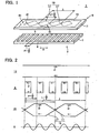
- Fig. 1 is a perspective view showing a brief structure of the device 1.
- the induction type displacement detector 1 comprises a scale 3 and a sensor head 5 arranged opposite thereto.
- the scale 3 is partly depicted in the longitudinal direction thereof.
- the longitudinal direction of the scale 3 corresponds to a measurement axis X.
- the sensor head 5 is spaced from the scale 3 by a certain gap and arranged movable along the measurement axis X.
- the device may also be configured such that the sensor head is stationary while the scale is movable. In a word, it is sufficient if the sensor head and the sensor are relatively movable in a direction along the measurement axis.
- the scale 3 includes an insulating board 7 composed of a glass epoxy resin.
- the board 7 may be composed of glass or silicon.
- a plurality of flux coupling windings 9 (an example of the flux coupling members) having the same shape are aligned along the measurement axis X.
- a plurality of flux coupling windings 9 are arrayed on the scale 3 along the measurement axis X.
- a flux coupling winding 9 is a rectangular linear conductor of which longitudinal direction is perpendicular to the measurement axis X.
- the linear conductor is composed of a low-resistance material such as aluminum, copper and gold.
- a passivation film, not shown, is formed over the insulating board 7 to cover the flux coupling windings 9.
- metal plates capable of interfering with flux coupling may be arranged periodically along the measurement axis X. Also in this case, a periodic signal can be obtained from a receiving winding 15 depending on the location of the sensor head 5 and employed in displacement detection, like when the windings 9 are arranged.
- the sensor head 5 includes an insulating board 11 composed of a glass epoxy resin. Alternatively, the board 11 may be composed of glass or silicon. On a surface of the board 11, opposite to the scale 3, a transmitting winding 13 (an example of the transmitting member) is formed. Therefore, the transmitting winding 13 is arranged on the sensor head 5.
- the transmitting winding 13 is shaped in a rectangle of which longitudinal direction is determined along the measurement axis X.
- the transmitting winding 13 is capable of flux coupling to the flux coupling windings 9.
- a single linear conductor may be employed as the transmitting member.
- a single receiving winding 15 is located inside the transmitting winding 13.
- the winding 15 is capable of flux coupling to the flux coupling windings 9.
- a plurality of receiving loops 17 aligned on the insulating board 11 along the measurement axis X configure the receiving winding 15.
- the receiving winding 15 includes a plurality of receiving loops 17 arrayed on the sensor head 5 along the measurement axis X.
- the receiving winding 15 is not limited to one but two or more may be provided.
- the present invention is also applicable to two receiving windings arranged with a phase difference of ⁇ /4 or three receiving windings arranged with a phase difference of ⁇ /6.
- a receiving loop 17 is a hexagonal linear conductor. Adjacent receiving loops 17 are linked through a three-dimensional intersection to configure a pair-loop 19.
- the pair-loop 19 has a length of ⁇ along the measurement axis X.
- a single receiving loop 17 has a length L of ⁇ /2 along the measurement axis X.
- the flux coupling windings 9 have a pitch P of ⁇ /5.
- a passivation film is formed over the insulating board 11 to cover the transmitting winding 13 and the receiving winding 15.
- the transmitting winding 13 and the receiving winding 15 have terminals 21, which are connected via wires to an IC (not shown) operative to compute and control for displacement measurements.
- the transmitting winding 13 and the receiving winding 15 are composed of the same material as that of the flux coupling winding 9. The above description is directed to the configuration of the induction type displacement detector 1.
- Fig. 2 is employed next to briefly describe operation of the induction type displacement detector 1.
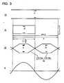
- Fig. 2 is an illustrative view of the operation. It shows plan views of the transmitting winding 13, the flux coupling winding 9 and the receiving winding 15 in part, and a waveform diagram of an output signal S provided from the receiving winding 15 as the sensor head moves relative to the scale.
- a transmitting drive signal (single-phase AC) is sent to the transmitting winding 13 to feed a drive current i1 flowing in the transmitting winding 13 clockwise when a certain time is noted.
- the transmitting winding 13 By the drive current i1 the transmitting winding 13 generates an alternating magnetic flux to make a flux coupling to the flux coupling windings 9.
- an induced current i2 flows in the flux coupling windings 9 counterclockwise.
- the flux coupling winding 9 generates an alternative flux to make a flux coupling to the receiving loops 17 of the receiving winding 15. This coupling causes an induced current i3 to flow in the receiving loops 17 clockwise.
- a sinusoidal output signal S is sent to the IC, not shown, from the receiving winding 15 as the sensor head moves relative to the scale.
- the IC samples the output signal S and converts it into digital values to compute the location of the sensor head 5 relative to the scale 3.
- the pair-loop 19 has a length of ⁇ while the flux coupling windings 9 have a pitch of ⁇ /5.
- the flux coupling windings 9 have a pitch P of ⁇ .
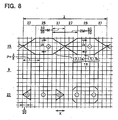
- Fig. 3 is an illustrative view of operation of the comparative example, which corresponds to Fig. 2.
- a receiving loop 17 (17b) does not overlap the flux coupling winding 9. Accordingly, an induced voltage is caused on a receiving loop 17a and no induced voltage is caused on the receiving loop 17b.
- the induced current 13 flows in the direction of the shown arrow and a sinusoidal output signal S is sent to the IC, not shown, from the receiving winding 15 as the sensor head moves relative to the scale.
- the induced current i3 exhibits a variation, which is described with reference to Fig. 4 taking the comparative example shown in Fig. 3 as an example.
- the flux coupling winding 9 most overlaps the receiving loop 17a as shown in (1)
- the induced current i3 flows as shown in Fig. 3 and reaches the positive maximum as shown in Fig. 4.
- the current i3 flowing in the receiving loop 17a matches with that in the receiving loop 17b. In this case, the current i3 is kept at zero.
- the flux coupling winding 9 most overlaps the receiving loop 17b as shown in (3), the induced current i3 reaches the negative maximum.
- the flux coupling windings 9 have a pitch P of ⁇ and accordingly the output signal S has a wavelength of ⁇ .
- the first embodiment of Fig. 2 the flux coupling windings 9 have a pitch P of ⁇ /5 and accordingly the output signal S has a wavelength of ⁇ /5. Therefore, the wavelength of the output signal S in the first embodiment is 1/5 that of the comparative example.
- the pitch P between the flux coupling windings 9 is made smaller to shorten the wavelength of the output signal S. According, it is possible to provide the induction type displacement detector with an improved resolution and high precision.
- the receiving loop 17 has a length L, which is same as that in the comparative example and equal to ⁇ /2. Therefore, in the first embodiment the pitch P between the flux coupling windings 9 can be made smaller without reducing the dimension of the receiving loop 17. This means that the pitch P between the flux coupling windings 9 can be reduced without suffering an influence from the limited dimension of the receiving loop 17 on the design rule. Therefore, a relatively inexpensive board such as a glass epoxy board can be employed as the insulating board 11 of the sensor head 5 to lower the production cost of the induction type displacement detector.
- the pitch P between the flux coupling windings 9 is described as ⁇ /5 though it may be ⁇ /N (where N is an odd number of 3 or more). The following description is given to the reason why N is determined to an odd number of 3 or more.
- Fig. 5 shows the flux coupling windings 9, the receiving winding 15 and an overlapped portion 23 therebetween where N is equal to 2, 4.
- the induced current 13 flowing in one receiving loop 17 (17a) of the pair-loop 19 is given a "+" sign while the induced current i3 flowing in the other receiving loop 17 (17b) is given a "-" sign.
- the overlapped portion 23 of the receiving loop 17a has the same area as that of the receiving loop 17b. Therefore, the induced current i3 flowing in the receiving loop 17a has the same intensity as that in the receiving loop 17b, resulting in cancellation of the induced current i3.
- Fig. 6 shows the flux coupling windings 9, the receiving winding 15 and an overlapped portion 23 therebetween, where N is equal to 3, 5, corresponding to Fig. 5.
- N is an odd number
- the receiving loop 17a is different in area of the overlapped portion 23 from the receiving loop 17b.
- the area of the "+" overlapped portion 23 is equal to about 13 squares while the area of the "-" overlapped portion 23 is equal to about 14 squares. Accordingly, the induced current i3 flowing in the receiving loop 17a can be made different in intensity from that in the receiving loop 17b to provide an output signal from the receiving winding 15.
- N is determined to an odd number of 3 or more.
- a second embodiment is mainly characterized in that twice the length of the side portion of the receiving loop is made smaller than the pitch between the flux coupling windings.
- Fig. 7 shows the flux coupling windings 9, the receiving winding 15 and the overlapped portion 23 therebetween according to a second embodiment.
- the receiving loop 17 has a central portion 25 extending along the measurement axis X, and two side portions 27 extending at an angle to the measurement axis X and located on both sides of the central portion 25. Adjacent receiving loops 17a, 17b are linked at the side portions 27 through a three-dimensional intersection.
- a symbol M denotes a length of the side portion 27 along the measurement axis X.
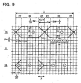
- Fig. 8 shows flux coupling windings 9, a receiving winding 15 and an overlapped portion 23 therebetween according to a comparative example to the second embodiment, corresponding to Fig. 7.
- the area of the "+" overlapped portion 23 is equal to 20 squares while the area of the "-" overlapped portion 23 is equal to 16 squares.
- the area of the "+" overlapped portion 23 is equal to about 13 squares while the area of the "-" overlapped portion 23 is equal to about 14 squares.
- the second embodiment has a larger difference between the area of the "+" overlapped portion 23 and the area of the "-" overlapped portion 23 and accordingly enhances the intensity of the output signal from the receiving winding 15.
- the second embodiment is also possible from this viewpoint to provide the induction type displacement detector with an improved resolution and high precision. If the length M of the side portion 27 is made excessively smaller (in other words, the tilt of the side portion 27 to the measurement axis X is made excessively larger), the output signal has a large waveform distortion. Accordingly, the waveform of the output signal goes away from an ideal waveform or a sin wave. The intensity of the output signal and the distortion of the output signal are related in a tradeoff. Therefore, the length M of the side portion 27 should be determined in consideration of the tradeoff.
- a third embodiment is mainly characterized in that three receiving windings are arranged with a phase difference of ⁇ /6 while the flux coupling windings are determined to have a pitch of ⁇ /5.
- the third embodiment is directed to the three-phase type that provides differentlyphase-shiftedoutput signals from three receiving windings.
- the flux coupling windings are same as those of the preceding embodiments and omitted from the following description, and three receiving windings are described.
- Fig. 10 is an illustrative view of three receiving windings 15a, 15b, 15c according to the third embodiment.
- the receiving windings 15a, 15b, 15c are arranged on the sensor head 5, insulated from each other and overlapped.
- the reference numeral 29 denotes a contact, which is described later.
- the receiving windings are shown in Fig. 10(B).
- the receiving winding 15b With reference to the phase (0°) of the receiving winding 15a, the receiving winding 15b has a difference of ⁇ /6 phase (60° phase) from the receiving winding 15a.
- the receiving winding 15c has a difference of ⁇ /3 phase (120° phase) from the receiving winding 15a.
- the three-phase type requires signals with a spatial phase difference of ⁇ /3.
- the receiving windings are arranged with a phase difference of ⁇ /6. Therefore, with reference to the phase (0°) of the signal received at the receiving winding 15a, the receiving winding 15b receives a ⁇ /6 phase-shifted signal and the receiving winding 15c receives a ⁇ /3 phase-shifted signal. In this state, a 2 ⁇ /3 phase-shifted signal can not be obtained. When the polarity is inverted, the ⁇ /6 phase-shifted signal is turned into the 2 ⁇ /3 phase-shifted signal. Therefore, in the third embodiment a signal inverter is provided to invert the polarity of the signal received at the receiving winding 15b to provide the 2 ⁇ /3 phase-shifted signal.
- the receiving windings 15a, 15b, 15c shown in Fig. 10 it is advantageous to arrange the receiving windings with a phase difference of ⁇ /3. Specifically, the receiving winding 15b is arranged with a phase difference of 2 ⁇ /3 from the receiving winding 15a.
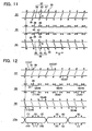
- Fig. 11 is a plan view of the three receiving windings 15a, 15b, 15c shown in Fig. 10 (A), which are decomposed into a first layered wire 31, a second layered wire 33 and a third layered wire 35.
- the first layered wire 31 is structured such that a pattern 37 is arranged repeatedly along the measurement axis X.
- the pattern 37 includes parallel portions 39, 41 paralleled with the measurement axis X and a tilt portion 43 tilted to the measurement axis X.
- the parallel portions 39, 41 are not opposed to each other but arranged on locations shifted along the measurement axis X and linked via the tilt portion 43.
- the pattern 37 has both ends serving as contacts 29, which are led out to outside the receiving winding.
- the second layered wire 33 includes patterns 45, 47 paralleled with the measurement axis X and opposed to each other. These patterns have contacts 29 at both ends, which are led out to outside the receiving winding.
- the patterns 45, 47 are arranged repeatedly along the measurement axis X.
- the third layered wire 35 is structured such that a symmetric pattern 49 of the pattern 37 is arranged repeatedly along the measurement axis X.
- These wires are connected with each other to configure the receiving windings 15a, 15b, 15c shown in Fig. 10 (A).
- the receiving winding 15a can be described as shown in Fig. 12.
- Connecting patterns (1)-(6) and connecting patterns (7)-(12) configure the receiving winding 15a.
- the contacts 29 are led out to outside the receiving windings 31, 33 and 35 but prevented from causing crosstalk. This is described with reference to the patterns (1) and (2) of Fig. 12.
- the contacts 29 are connected to the patterns (1) and (2) via respective leads 51 extending from the receiving winding to external.
- the leads 51 of the patterns (1) and (2) overlap and signals flow therein in opposite directions such that the magnetic fields generated at the leads 51 cancel each other out. Accordingly, it is possible to prevent the leads 51 from causing crosstalk.
- Fig. 13 is a plan view showing part of the receiving windings 15a, 15b, 15c and the flux coupling windings 9 when the pitch P between the flux coupling windings 9 is equal to ⁇ /3.
- these receiving windings are arranged with a phase difference of ⁇ /6. If the pitch P between the flux coupling windings 9 is determined to ⁇ /3, the output signals S from the receiving windings 15a, 15b, 15c have the same phase. In this case, three phase-shifted output signals can not be provided from the three receiving windings. Therefore, the pitch P of ⁇ /3 is excluded.
- the pitch P between the flux coupling windings 9 is determined to ⁇ /5.
- the third embodiment is described of the three-phase type.
- the second receiving winding is ⁇ /4 phase-shifted from the first receiving winding.
- the third receiving winding is ⁇ /2 phase-shifted from the first receiving winding
- the fourth receiving winding is 3 ⁇ /4 phase-shifted from the first receiving winding.
- the pitch between the flux coupling windings may be either ⁇ /5 or ⁇ /3.
- a fourth embodiment is mainly characterized in that a boundary between the central portion and the side portion of the receiving loop is formed smaller in tilt than the side portion.
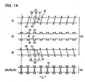
- Fig. 14 is an illustrative view of three receiving windings according to the fourth embodiment. The three receiving windings are decomposed into a first layered wire 31, a second layered wire 33 and a third layered wire 35 as shown in a plan view of Fig. 14(A) corresponding to Fig. 11.
- the tilt portion 43 has both ends 53 tilted smaller to the measurement axis X.
- the wires 31, 33, 35 are overlapped to configure the three receiving windings 15a, 15b, 15c as shown in Fig. 14(B), which corresponds to Fig. 10(A).
- Fig. 15 compares a pair-loop of the third embodiment with that of the fourth embodiment and shows (A) the pair-loop of the fourth embodiment and (B) the pair-loop of the third embodiment.
- a boundary 55 between the central portion 35 and the side portion 27 is formed smaller in tilt to the measurement axis X than the side portion 27.
- the boundary 55 corresponds to both ends 53 of the tilt portion 43.
- the tilt of both ends 53 of the tilt portion 43, or the tilt of the boundary 55 is therefore made smaller.
- the distance D between adjacent patterns 37 or the distance D between adjacent patterns 49 can be ensured.
- the area of the receiving loop overlapping the flux coupling winding that is, the intensity of the output signal from the receiving winding
- the tilt of the boundary 55 is made smaller than the tilt of the side portion 27 to reduce the waveform distortion of the output signal from the receiving winding. This is effective to approximate the waveform of the output signal to an ideal waveform or a sin wave.
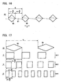
- Fig. 16 is a plan view of a receiving winding 57 of an induction type displacement detector according to a fifth embodiment.
- the receiving loops comprise pair-loops while in the fifth embodiment a space is provided in between adjacent receiving loops 59.
- Other parts than the receivingwinding 57 are similar to those in the preceding embodiments.
- the fifth embodiment will be described below in detail.
- the receiving loops 59 When the receiving loops 59 have a pitch of Q, the receiving loops 59 have a length L of Q/2 and adjacent receiving loops 59 have a space R of Q/2 therebetween.
- the receiving loops 59 have a diamond shape. Adjacent receiving loops 59 are connected through a wire 61 located in a lower layer beneath the receiving loops 59.
- the space between adjacent receiving loops 59 is a space corresponding to one receiving loop 59, This space is not limited in dimension.
- the flux coupling windings have a pitch P of Q/N (N is an integer of 2 or more) as described with reference to Fig. 17.
- Fig. 17 shows flux coupling windings 9 and the receiving winding 57 according to the fifth embodiment where N is equal to 2, 3, 4.
- N is equal to 2, 3, 4.
- a space of one receiving loop 59 is provided in between adjacent receiving loops 59. Accordingly, the induced currents flowing in the receiving loops 59 can not cancel each other out like in the pair-loop. Therefore, N may be either even or odd.
- the pitch P between the flux coupling windings 9 is determined to Q/N (N is an integer of 2 or more). Accordingly, for the same reason as in the first embodiment, it is possible to provide the induction type displacement detector with an improved resolution and high precision and lower the production cost of the induction type displacement detector.
- the three-phase type is also applicable to the fifth embodiment.
- Three receiving windings may be arranged with a phase difference of ⁇ /6 or arranged with a phase difference of ⁇ /3 as described in the third embodiment. From the viewpoint of elimination of the influence from the signal offset, it is effective to arrange three receiving windings with a phase difference of ⁇ /3.
Landscapes
- Physics & Mathematics (AREA)
- General Physics & Mathematics (AREA)
- Transmission And Conversion Of Sensor Element Output (AREA)
- Measurement Of Length, Angles, Or The Like Using Electric Or Magnetic Means (AREA)
Abstract
Description
- This application is based on and claims the benefit of priority from prior Japanese Patent Application No. 2004-297688, filed on October 12, 2004, the entire contents of which are incorporated herein by reference.
- The present invention relates to an induction type displacement detector operative to detect a displacement using inductive coupling (flux coupling), which is applicable to a caliper and a linear encoder.
- An induction type displacement detector is employed in precise measurements of linear displacements and angular displacements. A conventional induction type displacement detector comprises a scale having plates arrayed as flux coupling members at a certain pitch, and a sensor head arranged relatively movable and opposite to the scale. The sensor head has a transmitting winding and a receiving winding arranged thereon, which are capable of flux coupling to the plates (see JP-A 8-313296, Fig. 4, for example).
- For the purpose of providing the induction type displacement detector with an improved resolution and high precision, it is simply required to reduce a pitch between the plates serving as flux coupling members and a dimension of a receiving loop contained in the receiving winding. As the plates have simple shapes, the pitch between the plates can be narrowed easily. The receiving winding has a relatively complicated shape, however, because plural receiving loops are linked along the direction of the relative movement of the sensor head. In addition, when output signals from the receiving winding are subjected to interpolation to improve the resolution, plural receiving windings are arranged on the sensor head, phase-shifted and overlapped. In this case, the shapes of the receiving windings become more complicated.
- As the shape of the receiving winding is relatively complicated in this way, the receiving loop has a relatively large limited dimension on the design rule. The use of a thin-film multi-layered board or a high-density built-up board as a board for use in formation of the receiving winding thereon can reduce the limited dimension of the receiving loop while it elevates the production cost of the induction type displacement detector.
- The present invention has an object to provide an induction type displacement detector capable of achieving an improved resolution and high precision.
- In one aspect the present invention provides an induction type displacement detector, comprising: a scale; a sensor head arranged opposite to the scale and movable relative to the scale in a direction along a measurement axis; a transmitting member arranged on the sensor head; a receiving winding having a plurality of receiving loops arrayed on the sensor head along the measurement axis; and a plurality of flux coupling members capable of flux coupling to the transmitting member and the receiving winding and arrayed on the scale along the measurement axis, wherein adjacent receiving loops configure a pair-loop having a length of λ along the measurement axis, wherein each receiving loop has a length of λ/2 along the measurement axis, and the flux coupling members have a pitch of λ/N (where N is an odd number of 3 or more).
- In the induction type displacement detector according to one aspect of the present invention, adjacent receiving loops configure a pair-loop having a length of λ while the flux coupling members have a pitch of λ/N (where N is an odd number of 3 or more). Therefore, without suffering an influence from the limited dimension of the receiving loop on the design rule, the pitch between the flux coupling members can be reduced. Thus, the induction type displacement detector can be provided with an improved resolution and high precision. If N is an even number, a signal received at one receiving loop contained in the pair-loop and a signal received at the other receiving loop cancel each other and no output signal is provided from the receiving winding. Therefore, N is determined to an odd number.
- In the induction type displacement detector according to one aspect of the present invention, the receiving winding may be one of three such receiving windings arranged with a phase difference of λ/3 or λ/6, and the flux coupling members may have a pitch of λ/5.
- This is the so-called three-phase type. If the flux coupling members have a pitch of λ/3 in this type, the output signals from three receiving windings have the same phase. In this case, three output signals with different phases can not be provided and accordingly interpolation can not be executed. On the other hand, the smaller the pitch between the flux coupling members becomes, the lower the intensity of the output signal from each receiving winding becomes. Therefore, the flux coupling members may have a pitch of λ/5.
- In the induction type displacement detector according to one aspect of the present invention, the receiving winding may be one of two or four such receiving windings, which are arranged with a phase difference of λ/4. The present invention in one aspect is also applicable to the so-called two- or four-phase type.
- In the induction type displacement detector according to one aspect of the present invention, the receiving loops each may have a central portion extending along the measurement axis, and two side portions extending at an angle to the measurement axis and located on both sides of the central portion. In this case, twice the length of the side portion along the measurement axis may be smaller than a pitch between the flux coupling members. This is effective to enhance the intensity of the output signal from the receiving winding.
- In the induction type displacement detector according to one aspect of the present invention, a boundary between the central portion and the side portion may be formed smaller in tilt to the measurement axis than the side portion.
- This is effective to increase the area of the receiving winding overlapping the flux coupling member (that is, the intensity of the output signal from the receiving winding) without interfering with the design rule on the receiving loop.
- In another aspect the present invention provides an induction type displacement detector, comprising: a scale; a sensor head arranged opposite to the scale and movable relative to the scale along a measurement axis; a transmitting member arranged on the sensor head; a receiving winding having a plurality of receiving loops arrayed on the sensor head along the measurement axis such that a space is provided in between adjacent receiving loops; and a plurality of flux coupling members capable of flux coupling to the transmitting member and the receiving winding and arrayed on the scale along the measurement axis, wherein the receiving loops have a pitch of Q while the flux coupling members have a pitch of Q/N (where N is an integer of 2 or more).
- In the induction type displacement detector according to another aspect of the present invention, the receiving loops have a pitch of Q while the flux coupling members have a pitch of Q/N (where N is an integer of 2 or more). Therefore, without suffering an influence from the limited dimension of the receiving loop on the design rule, the pitch between the flux coupling members can be reduced. Thus, the induction type displacement detector can be provided with an improved resolution and high precision. In the induction type displacement detector according to another aspect of the present invention, a space of one receiving loop is provided in between adjacent receiving loops. Accordingly, N may be either even or odd.
- Thus, the present invention can provide the induction type displacement detector with an improved resolution and high precision.
-
- Fig. 1 is a perspective view showing a brief structure of an induction type displacement detector according to a first embodiment;
- Fig. 2 is an illustrative view of operation of the induction type displacement detector according to the first embodiment;
- Fig. 3 is an illustrative view of operation of a comparative example to the first embodiment;
- Fig. 4 is an illustrative view of a variation in induced current i3 in the comparative example shown in Fig. 3;
- Fig. 5 shows flux coupling windings, a receiving winding and an overlapped portion therebetween according to another comparative example to the first embodiment;
- Fig. 6 shows flux coupling windings, a receiving winding and an overlapped portion therebetween according to the first' embodiment;
- Fig. 7 shows flux coupling windings, a receiving winding and an overlapped portion therebetween according to a second embodiment;
- Fig. 8 shows flux coupling windings, a receiving winding and an overlappedportion there between according to a comparative example to the second embodiment;
- Fig. 9 shows flux coupling windings, a receiving winding and an overlapped portion therebetween according to another comparative example to the second embodiment;
- Fig. 10 is an illustrative view of three receiving windings according to a third embodiment;
- Fig. 11 is a plan view of the three receiving windings shown in Fig. 10 (A), which are decomposed into a first layered wire, a second layered wire and a third layered wire;
- Fig. 12 shows patterns configuring one of the three receiving windings in the third embodiment;
- Fig. 13 is an illustrative view of operation of an induction type displacement detector of a comparative example to the third embodiment;
- Fig. 14 is an illustrative view of three receiving windings according to a fourth embodiment;
- Fig. 15 compares a pair-loop of the third embodiment with that of the fourth embodiment;
- Fig. 16 is a plan view of a receiving winding according to a fourth embodiment; and
- Fig. 17 shows flux coupling windings and the receiving winding according to the fifth embodiment.
- Embodiments of the present invention will now be described with reference to the drawings. In the figures illustrative of the embodiments, the same parts as those denoted with the reference numerals already described are given the same reference numerals and omitted from the following description.
- An induction type displacement detector according to a first embodiment is mainly characterized as follows. When adjacent receiving loops configure a pair-loop (also referred to as a twisted pair) having a length of λ along a measurement axis, flux coupling windings (an example of flux coupling members) are determined to have a pitch of λ/5. The induction type displacement detector according to the first embodiment is described first about the structure thereof. Fig. 1 is a perspective view showing a brief structure of the
device 1. - The induction
type displacement detector 1 comprises ascale 3 and asensor head 5 arranged opposite thereto. Thescale 3 is partly depicted in the longitudinal direction thereof. The longitudinal direction of thescale 3 corresponds to a measurement axis X. Thesensor head 5 is spaced from thescale 3 by a certain gap and arranged movable along the measurement axis X. The device may also be configured such that the sensor head is stationary while the scale is movable. In a word, it is sufficient if the sensor head and the sensor are relatively movable in a direction along the measurement axis. - The
scale 3 includes an insulatingboard 7 composed of a glass epoxy resin. Alternatively, theboard 7 may be composed of glass or silicon. On a surface of theboard 7, opposite to thesensor head 5, a plurality of flux coupling windings 9 (an example of the flux coupling members) having the same shape are aligned along the measurement axis X. In other words, a plurality offlux coupling windings 9 are arrayed on thescale 3 along the measurement axis X. - A flux coupling winding 9 is a rectangular linear conductor of which longitudinal direction is perpendicular to the measurement axis X. The linear conductor is composed of a low-resistance material such as aluminum, copper and gold. A passivation film, not shown, is formed over the insulating
board 7 to cover theflux coupling windings 9. Instead of thewindings 9, metal plates capable of interfering with flux coupling may be arranged periodically along the measurement axis X. Also in this case, a periodic signal can be obtained from a receiving winding 15 depending on the location of thesensor head 5 and employed in displacement detection, like when thewindings 9 are arranged. - The
sensor head 5 includes an insulatingboard 11 composed of a glass epoxy resin. Alternatively, theboard 11 may be composed of glass or silicon. On a surface of theboard 11, opposite to thescale 3, a transmitting winding 13 (an example of the transmitting member) is formed. Therefore, the transmitting winding 13 is arranged on thesensor head 5. The transmitting winding 13 is shaped in a rectangle of which longitudinal direction is determined along the measurement axis X. The transmitting winding 13 is capable of flux coupling to theflux coupling windings 9. Instead of the transmitting winding 13, a single linear conductor may be employed as the transmitting member. - On the surface of the insulating
board 11, opposite to thescale 3, a single receiving winding 15 is located inside the transmitting winding 13. The winding 15 is capable of flux coupling to theflux coupling windings 9. A plurality of receivingloops 17 aligned on the insulatingboard 11 along the measurement axis X configure the receiving winding 15. In other words, the receiving winding 15 includes a plurality of receivingloops 17 arrayed on thesensor head 5 along the measurement axis X. The receiving winding 15 is not limited to one but two or more may be provided. For example, the present invention is also applicable to two receiving windings arranged with a phase difference of λ/4 or three receiving windings arranged with a phase difference of λ/6. - A receiving
loop 17 is a hexagonal linear conductor. Adjacent receivingloops 17 are linked through a three-dimensional intersection to configure a pair-loop 19. The pair-loop 19 has a length of λ along the measurement axis X. Asingle receiving loop 17 has a length L of λ/2 along the measurement axis X. Theflux coupling windings 9 have a pitch P of λ/5. - A passivation film, not shown, is formed over the insulating
board 11 to cover the transmitting winding 13 and the receiving winding 15. The transmitting winding 13 and the receiving winding 15 haveterminals 21, which are connected via wires to an IC (not shown) operative to compute and control for displacement measurements. The transmitting winding 13 and the receiving winding 15 are composed of the same material as that of the flux coupling winding 9. The above description is directed to the configuration of the inductiontype displacement detector 1. - Fig. 2 is employed next to briefly describe operation of the induction
type displacement detector 1. Fig. 2 is an illustrative view of the operation. It shows plan views of the transmitting winding 13, the flux coupling winding 9 and the receiving winding 15 in part, and a waveform diagram of an output signal S provided from the receiving winding 15 as the sensor head moves relative to the scale. - A transmitting drive signal (single-phase AC) is sent to the transmitting winding 13 to feed a drive current i1 flowing in the transmitting winding 13 clockwise when a certain time is noted. By the drive current i1 the transmitting winding 13 generates an alternating magnetic flux to make a flux coupling to the
flux coupling windings 9. As a result, an induced current i2 flows in theflux coupling windings 9 counterclockwise. By this induced current, the flux coupling winding 9 generates an alternative flux to make a flux coupling to the receivingloops 17 of the receiving winding 15. This coupling causes an induced current i3 to flow in the receivingloops 17 clockwise. As a result, a sinusoidal output signal S is sent to the IC, not shown, from the receiving winding 15 as the sensor head moves relative to the scale. The IC samples the output signal S and converts it into digital values to compute the location of thesensor head 5 relative to thescale 3. - As described above, in the first embodiment the pair-
loop 19 has a length of λ while theflux coupling windings 9 have a pitch of λ/5. On the contrary, in an induction type displacement detector according to a comparative example, theflux coupling windings 9 have a pitch P of λ. Fig. 3 is an illustrative view of operation of the comparative example, which corresponds to Fig. 2. In a positional relation between the flux coupling winding 9 and the receiving winding 15 shown in Fig. 3, a receiving loop 17 (17b) does not overlap the flux coupling winding 9. Accordingly, an induced voltage is caused on a receivingloop 17a and no induced voltage is caused on the receivingloop 17b. Thus, the induced current 13 flows in the direction of the shown arrow and a sinusoidal output signal S is sent to the IC, not shown, from the receiving winding 15 as the sensor head moves relative to the scale. - In accordance with the movement of the sensor head relative to the scale, the induced current i3 exhibits a variation, which is described with reference to Fig. 4 taking the comparative example shown in Fig. 3 as an example. When the flux coupling winding 9 most overlaps the receiving
loop 17a as shown in (1), the induced current i3 flows as shown in Fig. 3 and reaches the positive maximum as shown in Fig. 4. When the flux coupling winding 9 overlaps the receivingloop 17a same as the flux coupling winding 9 overlaps the receivingloop 17b as shown in (2), the current i3 flowing in the receivingloop 17a matches with that in the receivingloop 17b. In this case, the current i3 is kept at zero. When the flux coupling winding 9 most overlaps the receivingloop 17b as shown in (3), the induced current i3 reaches the negative maximum. - In the comparative example the
flux coupling windings 9 have a pitch P of λ and accordingly the output signal S has a wavelength of λ. On the contrary, in the first embodiment of Fig. 2 theflux coupling windings 9 have a pitch P of λ/5 and accordingly the output signal S has a wavelength of λ/5. Therefore, the wavelength of the output signal S in the first embodiment is 1/5 that of the comparative example. Thus, in the first embodiment the pitch P between theflux coupling windings 9 is made smaller to shorten the wavelength of the output signal S. According, it is possible to provide the induction type displacement detector with an improved resolution and high precision. - In the first embodiment the receiving
loop 17 has a length L, which is same as that in the comparative example and equal to λ/2. Therefore, in the first embodiment the pitch P between theflux coupling windings 9 can be made smaller without reducing the dimension of the receivingloop 17. This means that the pitch P between theflux coupling windings 9 can be reduced without suffering an influence from the limited dimension of the receivingloop 17 on the design rule. Therefore, a relatively inexpensive board such as a glass epoxy board can be employed as the insulatingboard 11 of thesensor head 5 to lower the production cost of the induction type displacement detector. - In the first embodiment the pitch P between the
flux coupling windings 9 is described as λ/5 though it may be λ/N (where N is an odd number of 3 or more). The following description is given to the reason why N is determined to an odd number of 3 or more. Fig. 5 shows theflux coupling windings 9, the receiving winding 15 and an overlappedportion 23 therebetween where N is equal to 2, 4. In this case, the induced current 13 flowing in one receiving loop 17 (17a) of the pair-loop 19 is given a "+" sign while the induced current i3 flowing in the other receiving loop 17 (17b) is given a "-" sign. - The overlapped
portion 23 of the receivingloop 17a has the same area as that of the receivingloop 17b. Therefore, the induced current i3 flowing in the receivingloop 17a has the same intensity as that in the receivingloop 17b, resulting in cancellation of the induced current i3. - On the other hand, Fig. 6 shows the
flux coupling windings 9, the receiving winding 15 and an overlappedportion 23 therebetween, where N is equal to 3, 5, corresponding to Fig. 5. When N is an odd number, the receivingloop 17a is different in area of the overlappedportion 23 from the receivingloop 17b. For example, when N = 5, the area of the "+" overlappedportion 23 is equal to about 13 squares while the area of the "-" overlappedportion 23 is equal to about 14 squares. Accordingly, the induced current i3 flowing in the receivingloop 17a can be made different in intensity from that in the receivingloop 17b to provide an output signal from the receiving winding 15. - As above, when N is equal to an even number, the signal received at the receiving
loop 17a and the signal received at the receivingloop 17b cancel each other out. Accordingly, no output signal can be obtained from the receiving winding 15. Thus, N is determined to an odd number of 3 or more. - A second embodiment is mainly characterized in that twice the length of the side portion of the receiving loop is made smaller than the pitch between the flux coupling windings. Fig. 7 shows the
flux coupling windings 9, the receiving winding 15 and the overlappedportion 23 therebetween according to a second embodiment. - In the second embodiment the receiving
loop 17 has acentral portion 25 extending along the measurement axis X, and twoside portions 27 extending at an angle to the measurement axis X and located on both sides of thecentral portion 25.Adjacent receiving loops side portions 27 through a three-dimensional intersection. - A symbol M denotes a length of the
side portion 27 along the measurement axis X. The length M is equal to λ/20. Twice the length M, that is, 2M (= λ/10) is determined smaller than the pitch P (= X/5) between theflux coupling windings 9. A primary effect of the second embodiment is described. - Fig. 8 shows
flux coupling windings 9, a receiving winding 15 and an overlappedportion 23 therebetween according to a comparative example to the second embodiment, corresponding to Fig. 7. Theside portion 27 of the comparative example has a length M of 3λ/20. Therefore, different from the second embodiment, in the comparative example, 2M (= 3λ/10) is larger than the pitch P (= λ/5) between theflux coupling windings 9. - In the second embodiment shown in Fig. 7 the area of the "+" overlapped
portion 23 is equal to 20 squares while the area of the "-" overlappedportion 23 is equal to 16 squares. On the other hand, in the comparative example shown in Fig. 8 the area of the "+" overlappedportion 23 is equal to about 13 squares while the area of the "-" overlappedportion 23 is equal to about 14 squares. - Therefore, in comparison with the comparative example, the second embodiment has a larger difference between the area of the "+" overlapped
portion 23 and the area of the "-" overlappedportion 23 and accordingly enhances the intensity of the output signal from the receiving winding 15. - As the length M of the
side portion 27 decreases (in other words, the tilt of theside portion 27 to the measurement axis X increases) in this way, the difference between the area of the "+" overlappedportion 23 and the area of the "-" overlappedportion 23 grows. As a result, the intensity of the output signal is enhanced. - If the pitch P between the
flux coupling windings 9 is equal to 2M, no output signal can be obtained because the area of the "+" overlappedportion 23 and the area of the "-" overlappedportion 23 have no difference therebetween as shown in another comparative example of Fig. 9. - As described above, making twice the length M of the
side portion 27 along the measurement axis X smaller than the pitch P between theflux coupling members 9 enhances the intensity of the output signal. The second embodiment is also possible from this viewpoint to provide the induction type displacement detector with an improved resolution and high precision. If the length M of theside portion 27 is made excessively smaller (in other words, the tilt of theside portion 27 to the measurement axis X is made excessively larger), the output signal has a large waveform distortion. Accordingly, the waveform of the output signal goes away from an ideal waveform or a sin wave. The intensity of the output signal and the distortion of the output signal are related in a tradeoff. Therefore, the length M of theside portion 27 should be determined in consideration of the tradeoff. - A third embodiment is mainly characterized in that three receiving windings are arranged with a phase difference of λ/6 while the flux coupling windings are determined to have a pitch of λ/5. The third embodiment is directed to the three-phase type that provides differentlyphase-shiftedoutput signals from three receiving windings. In the third embodiment, the flux coupling windings are same as those of the preceding embodiments and omitted from the following description, and three receiving windings are described.
- Fig. 10 is an illustrative view of three receiving
windings windings sensor head 5, insulated from each other and overlapped. Thereference numeral 29 denotes a contact, which is described later. The receiving windings are shown in Fig. 10(B). With reference to the phase (0°) of the receiving winding 15a, the receiving winding 15b has a difference of λ/6 phase (60° phase) from the receiving winding 15a. The receiving winding 15c has a difference of λ/3 phase (120° phase) from the receiving winding 15a. - The three-phase type requires signals with a spatial phase difference of λ/3. In the third embodiment the receiving windings are arranged with a phase difference of λ/6. Therefore, with reference to the phase (0°) of the signal received at the receiving winding 15a, the receiving winding 15b receives a λ/6 phase-shifted signal and the receiving winding 15c receives a λ/3 phase-shifted signal. In this state, a 2λ/3 phase-shifted signal can not be obtained. When the polarity is inverted, the λ/6 phase-shifted signal is turned into the 2λ/3 phase-shifted signal. Therefore, in the third embodiment a signal inverter is provided to invert the polarity of the signal received at the receiving winding 15b to provide the 2λ/3 phase-shifted signal.
- If a signal offset causes a problem on the arrangement of the receiving
windings - Fig. 11 is a plan view of the three receiving
windings layered wire 31, a secondlayered wire 33 and a thirdlayered wire 35. The firstlayered wire 31 is structured such that apattern 37 is arranged repeatedly along the measurement axis X. Thepattern 37 includesparallel portions tilt portion 43 tilted to the measurement axis X. Theparallel portions tilt portion 43. Thepattern 37 has both ends serving ascontacts 29, which are led out to outside the receiving winding. - The second
layered wire 33 includespatterns contacts 29 at both ends, which are led out to outside the receiving winding. Thepatterns layered wire 35 is structured such that asymmetric pattern 49 of thepattern 37 is arranged repeatedly along the measurement axis X. - These wires are connected with each other to configure the receiving
windings - The
contacts 29 are led out to outside the receivingwindings contacts 29 are connected to the patterns (1) and (2) via respective leads 51 extending from the receiving winding to external. The leads 51 of the patterns (1) and (2) overlap and signals flow therein in opposite directions such that the magnetic fields generated at theleads 51 cancel each other out. Accordingly, it is possible to prevent theleads 51 from causing crosstalk. - The following description is given to the reason why the pitch between the flux coupling windings is determined to λ/5. Fig. 13 is a plan view showing part of the receiving
windings flux coupling windings 9 when the pitch P between theflux coupling windings 9 is equal to λ/3. In order to provide three phase-shifted output signals from the receivingwindings flux coupling windings 9 is determined to λ/3, the output signals S from the receivingwindings - On the other hand, the smaller the pitch P between the
flux coupling windings 9 becomes, the lower the intensities of the output signals from the receivingwindings windings 9 is determined to λ/5. - The third embodiment is described of the three-phase type. In the two-phase type, with reference to the phase of the first receiving winding, the second receiving winding is λ/4 phase-shifted from the first receiving winding. In the four-phase type, in addition to the receiving winding of the two-phase type, the third receiving winding is λ/2 phase-shifted from the first receiving winding, and the fourth receiving winding is 3λ/4 phase-shifted from the first receiving winding. In the two-phase and four-phase types, the pitch between the flux coupling windings may be either λ/5 or λ/3.
- A fourth embodiment is mainly characterized in that a boundary between the central portion and the side portion of the receiving loop is formed smaller in tilt than the side portion. Fig. 14 is an illustrative view of three receiving windings according to the fourth embodiment. The three receiving windings are decomposed into a first
layered wire 31, a secondlayered wire 33 and a thirdlayered wire 35 as shown in a plan view of Fig. 14(A) corresponding to Fig. 11. - The
tilt portion 43 has both ends 53 tilted smaller to the measurement axis X. Thewires windings - An effect of the fourth embodiment is described with reference to Figs. 11, 14 and 15. Fig. 15 compares a pair-loop of the third embodiment with that of the fourth embodiment and shows (A) the pair-loop of the fourth embodiment and (B) the pair-loop of the third embodiment. In the receiving
loop 17 contained in the pair-loop of the fourth embodiment, aboundary 55 between thecentral portion 35 and theside portion 27 is formed smaller in tilt to the measurement axis X than theside portion 27. Theboundary 55 corresponds to both ends 53 of thetilt portion 43. - The larger the
side portion 27 tilts, the more the area of the receivingloop 17 overlapping the flux coupling winding increases and the larger the intensity of the output signal enhances by the extent. If theside portion 27 is tilted larger, however, in the third embodiment a distance D betweenadjacent patterns 37 or a distance D betweenadjacent patterns 49 is shortened so as to interfere with the design rule as shown in Fig. 11. - In the fourth embodiment of Fig. 14, the tilt of both ends 53 of the
tilt portion 43, or the tilt of theboundary 55, is therefore made smaller. As a result, the distance D betweenadjacent patterns 37 or the distance D betweenadjacent patterns 49 can be ensured. In addition, the area of the receiving loop overlapping the flux coupling winding (that is, the intensity of the output signal from the receiving winding) can be made larger compared to the third embodiment. - In the fourth embodiment the tilt of the
boundary 55 is made smaller than the tilt of theside portion 27 to reduce the waveform distortion of the output signal from the receiving winding. This is effective to approximate the waveform of the output signal to an ideal waveform or a sin wave. - Fig. 16 is a plan view of a receiving winding 57 of an induction type displacement detector according to a fifth embodiment. In the induction type displacement detectors according to the preceding embodiments the receiving loops comprise pair-loops while in the fifth embodiment a space is provided in between adjacent receiving
loops 59. Other parts than thereceivingwinding 57 are similar to those in the preceding embodiments. The fifth embodiment will be described below in detail. - When the receiving
loops 59 have a pitch of Q, the receivingloops 59 have a length L of Q/2 and adjacent receivingloops 59 have a space R of Q/2 therebetween. The receivingloops 59 have a diamond shape. Adjacent receivingloops 59 are connected through awire 61 located in a lower layer beneath the receivingloops 59. The space between adjacent receivingloops 59 is a space corresponding to one receivingloop 59, This space is not limited in dimension. - In the fifth embodiment the flux coupling windings have a pitch P of Q/N (N is an integer of 2 or more) as described with reference to Fig. 17. Fig. 17 shows
flux coupling windings 9 and the receiving winding 57 according to the fifth embodiment where N is equal to 2, 3, 4. In the fifth embodiment a space of one receivingloop 59 is provided in between adjacent receivingloops 59. Accordingly, the induced currents flowing in the receivingloops 59 can not cancel each other out like in the pair-loop. Therefore, N may be either even or odd. - In the fifth embodiment, relative to the pitch Q between the receiving
loops 59, the pitch P between theflux coupling windings 9 is determined to Q/N (N is an integer of 2 or more). Accordingly, for the same reason as in the first embodiment, it is possible to provide the induction type displacement detector with an improved resolution and high precision and lower the production cost of the induction type displacement detector. - The three-phase type is also applicable to the fifth embodiment. Three receiving windings may be arranged with a phase difference of λ/6 or arranged with a phase difference of λ/3 as described in the third embodiment. From the viewpoint of elimination of the influence from the signal offset, it is effective to arrange three receiving windings with a phase difference of λ/3.
Claims (9)
- An induction type displacement detector, comprising:a scale;a sensor head arranged opposite to said scale and movable relative to said scale in a direction along a measurement axis;a transmitting member arranged on said sensor head;a receiving winding having a plurality of receiving loops arrayed on said sensor head along said measurement axis; anda plurality of flux coupling members capable of flux coupling to said transmitting member and said receiving winding and arrayed on said scale along said measurement axis,wherein adjacent receiving loops configure a pair-loop having a length of λ along said measurement axis,wherein each receiving loop has a length of λ/2 along said measurement axis, and said flux coupling members have a pitch of λ/N (where N is an odd number of 3 or more).
- The induction type displacement detector according to claim 1, wherein said receiving winding is one of three such receiving windings arranged with a phase difference of λ/3 or λ/6, and
wherein said flux coupling members have a pitch of λ/5. - The induction type displacement detector according to claim 1, wherein said receiving winding is one of two or four such receiving windings arranged with a phase difference of λ/ 4.
- The induction type displacement detector according to claim 1, wherein said flux coupling members are covered in a passivation film on said scale.
- The induction type displacement detector according to claim 1, wherein said transmitting member is formed in a rectangle with the longitudinal direction arranged along said measurement axis.
- The induction type displacement detector according to claim 1, wherein adjacent receiving loops configure a pair-loop linked through a three-dimensional intersection.
- The induction type displacement detector according to claim 1, wherein said receiving loops each have a central portion extending along said measurement axis, and two side portions extending at an angle to said measurement axis and located on both sides of said central portion, and
wherein twice the length of said side portion along said measurement axis is smaller than a pitch between said flux coupling members. - The induction type displacement detector according to claim 7, wherein a boundary.between said central portion and said side portion is formed smaller in tilt to said measurement axis than said side portion.
- An induction type displacement detector, comprising:a scale;a sensor head arranged opposite to said scale and movable relative to said scale in a direction along a measurement axis;a transmitting member arranged on said sensor head;a receiving winding having a plurality of receiving loops arrayed on said sensor head along said measurement axis such that a space is provided in between adjacent receiving loops; anda plurality of flux coupling members capable of flux coupling to said transmitting member and said receiving winding and arrayed on said scale along said measurement axis,wherein said receiving loops have a pitch of Q, and said flux coupling members have a pitch of Q/N (where N is an integer of 2 or more).
Applications Claiming Priority (1)
| Application Number | Priority Date | Filing Date | Title |
|---|---|---|---|
| JP2004297688A JP4615955B2 (en) | 2004-10-12 | 2004-10-12 | Inductive displacement detector |
Publications (3)
| Publication Number | Publication Date |
|---|---|
| EP1647809A2 true EP1647809A2 (en) | 2006-04-19 |
| EP1647809A3 EP1647809A3 (en) | 2006-08-30 |
| EP1647809B1 EP1647809B1 (en) | 2008-08-13 |
Family
ID=35708417
Family Applications (1)
| Application Number | Title | Priority Date | Filing Date |
|---|---|---|---|
| EP05022286A Expired - Lifetime EP1647809B1 (en) | 2004-10-12 | 2005-10-12 | Induction type displacement detector |
Country Status (5)
| Country | Link |
|---|---|
| US (1) | US7196510B2 (en) |
| EP (1) | EP1647809B1 (en) |
| JP (1) | JP4615955B2 (en) |
| CN (1) | CN1776372B (en) |
| DE (1) | DE602005008850D1 (en) |
Families Citing this family (32)
| Publication number | Priority date | Publication date | Assignee | Title |
|---|---|---|---|---|
| US7932715B2 (en) * | 2004-12-15 | 2011-04-26 | Mark Anthony Howard | Inductive detector with variable width loops on first and second surfaces of substrate |
| US7652469B2 (en) * | 2006-07-19 | 2010-01-26 | Advanced Sensor Technology Limited | Inductive position sensor |
| JP5224838B2 (en) * | 2008-02-04 | 2013-07-03 | 株式会社ミツトヨ | Electromagnetic induction encoder |
| FR2935485B1 (en) * | 2008-08-28 | 2010-09-10 | Roulements Soc Nouvelle | SYSTEM AND METHOD FOR MEASURING THE AXIAL MOTION OF A ROTATING MOBILE WORKPIECE |
| JP5249279B2 (en) * | 2010-04-19 | 2013-07-31 | 愛三工業株式会社 | Position sensor |
| DE102011115027A1 (en) * | 2011-10-07 | 2013-04-11 | Polytec Gmbh | Coherence grid interferometer and method for spatially resolved optical measurement of the surface geometry of an object |
| JP6134964B2 (en) * | 2012-11-12 | 2017-05-31 | 株式会社ミツトヨ | Inductive displacement detector |
| FR3002034B1 (en) * | 2013-02-12 | 2015-03-20 | Continental Automotive France | INDUCTIVE POSITION SENSOR |
| US9214936B2 (en) * | 2013-06-18 | 2015-12-15 | Hyundai Motor Company | Non-contact sensing module and method of manufacturing the same |
| JP6475936B2 (en) * | 2014-08-19 | 2019-02-27 | 株式会社ミツトヨ | Encoder scale and manufacturing method thereof |
| FR3031587B1 (en) * | 2015-01-13 | 2018-11-16 | Hutchinson | INDUCTIVE DISPLACEMENT SENSORS |
| FR3031588B1 (en) * | 2015-01-13 | 2018-11-16 | Hutchinson | INDUCTIVE DISPLACEMENT SENSORS |
| DE102015225695A1 (en) * | 2015-12-17 | 2017-06-22 | Robert Bosch Gmbh | Device and method for determining a relative displacement |
| JP6021136B1 (en) * | 2016-02-03 | 2016-11-09 | 三菱重工工作機械株式会社 | Electromagnetic induction type position detector |
| US9927261B1 (en) * | 2016-09-23 | 2018-03-27 | Sagentia Ltd. | Inductive sensor device for use with a distance measurement device |
| KR102040838B1 (en) * | 2017-11-06 | 2019-11-06 | 주식회사 상신정공 | Movement detection device of vehicle control element |
| JP7118627B2 (en) * | 2017-12-01 | 2022-08-16 | 株式会社ミツトヨ | Electromagnetic induction position detector |
| US11359909B2 (en) | 2018-01-23 | 2022-06-14 | Amiteq Co., Ltd. | Induction-type rotation detection device |
| CN108195293B (en) | 2018-03-26 | 2024-05-10 | 磐石电气(常州)有限公司 | A digital displacement sensor and a displacement measurement method thereof |
| US10718147B2 (en) | 2018-04-06 | 2020-07-21 | Tyco Fire & Security Gmbh | Optical displacement detector with adjustable pattern direction |
| US12535339B2 (en) * | 2018-06-28 | 2026-01-27 | Mitutoyo Corporation | Scale configuration for inductive position encoder |
| CN110487162B (en) | 2019-09-29 | 2020-09-08 | 桂林广陆数字测控有限公司 | Hybrid positioning electromagnetic induction type displacement sensor |
| DE102019128477A1 (en) * | 2019-10-22 | 2021-04-22 | HELLA GmbH & Co. KGaA | Sensor system for vehicles, in particular motor vehicles, for detecting the vehicle speed, the vehicle level and / or the state of the vehicle suspension, arrangement for such a sensor system and vehicle with such a sensor system |
| CN113008119B (en) * | 2019-12-19 | 2022-11-25 | 通用技术集团国测时栅科技有限公司 | Time-sharing multiplexing absolute time grating linear displacement sensor |
| EP3936829B1 (en) * | 2020-07-10 | 2023-08-30 | Renesas Electronics America Inc. | Inductive position sensor comprising at least one transmit coil, an absolute position receive coil pair, a high-resolution position receive coil pair and a conductive moving target |
| US11713983B2 (en) | 2021-06-30 | 2023-08-01 | Mitutoyo Corporation | Sensing winding configuration for inductive position encoder |
| US12072213B2 (en) | 2022-08-31 | 2024-08-27 | Mitutoyo Corporation | Inductive position encoder utilizing slanted scale pattern |
| US12072212B2 (en) | 2022-08-31 | 2024-08-27 | Mitutoyo Corporation | Inductive position encoder utilizing transmissive configuration |
| US12385764B2 (en) | 2022-12-30 | 2025-08-12 | Mitutoyo Corporation | Absolute position encoder utilizing single track configuration |
| US12546628B2 (en) | 2023-10-30 | 2026-02-10 | Mitutoyo Corporation | Inductive encoder with shield structures |
| US12553746B2 (en) | 2023-12-20 | 2026-02-17 | Mitutoyo Corporation | Measuring instrument with linear encoder tracks and arc motion |
| US12553747B2 (en) | 2023-12-20 | 2026-02-17 | Mitutoyo Corporation | Measuring instrument with arc encoder tracks |
Citations (1)
| Publication number | Priority date | Publication date | Assignee | Title |
|---|---|---|---|---|
| JPH08313296A (en) | 1995-05-23 | 1996-11-29 | Sankyo Seiki Mfg Co Ltd | Magnetic detecting apparatus |
Family Cites Families (10)
| Publication number | Priority date | Publication date | Assignee | Title |
|---|---|---|---|---|
| US4697144A (en) * | 1984-04-19 | 1987-09-29 | Verify Electronics Limited | Position sensing apparatus |
| DE3642607A1 (en) * | 1986-12-13 | 1988-06-23 | Bosch Gmbh Robert | Position measurement transmitter |
| US5574381A (en) * | 1995-01-06 | 1996-11-12 | Mitutoyo Corporation | Sealed mechanical configuration for electronic calipers for reliable operation in contaminated environments |
| EP0743508A2 (en) * | 1995-05-16 | 1996-11-20 | Mitutoyo Corporation | Induced current position transducer |
| GB9523991D0 (en) * | 1995-11-23 | 1996-01-24 | Scient Generics Ltd | Position encoder |
| US6002250A (en) * | 1996-05-13 | 1999-12-14 | Mitutoyo Corporation | Electronic linear scale using a self-contained, low-power inductive position transducer |
| US5886519A (en) * | 1997-01-29 | 1999-03-23 | Mitutoyo Corporation | Multi-scale induced current absolute position transducer |
| JPH116708A (en) * | 1997-06-16 | 1999-01-12 | Mitsutoyo Corp | Inductive position measuring unit |
| EP1164358B1 (en) * | 2000-06-16 | 2005-08-24 | AMO Automatisierung Messtechnik Optik GmbH | Inductive length measuring system |
| JP2004245738A (en) * | 2003-02-14 | 2004-09-02 | Mitsutoyo Corp | Induction type position detector |
-
2004
- 2004-10-12 JP JP2004297688A patent/JP4615955B2/en not_active Expired - Fee Related
-
2005
- 2005-10-12 EP EP05022286A patent/EP1647809B1/en not_active Expired - Lifetime
- 2005-10-12 CN CN2005101315546A patent/CN1776372B/en not_active Expired - Lifetime
- 2005-10-12 DE DE602005008850T patent/DE602005008850D1/en not_active Expired - Lifetime
- 2005-10-12 US US11/248,513 patent/US7196510B2/en not_active Expired - Lifetime
Patent Citations (1)
| Publication number | Priority date | Publication date | Assignee | Title |
|---|---|---|---|---|
| JPH08313296A (en) | 1995-05-23 | 1996-11-29 | Sankyo Seiki Mfg Co Ltd | Magnetic detecting apparatus |
Also Published As
| Publication number | Publication date |
|---|---|
| CN1776372A (en) | 2006-05-24 |
| EP1647809B1 (en) | 2008-08-13 |
| US7196510B2 (en) | 2007-03-27 |
| CN1776372B (en) | 2010-06-16 |
| JP4615955B2 (en) | 2011-01-19 |
| EP1647809A3 (en) | 2006-08-30 |
| US20060076949A1 (en) | 2006-04-13 |
| DE602005008850D1 (en) | 2008-09-25 |
| JP2006112815A (en) | 2006-04-27 |
Similar Documents
| Publication | Publication Date | Title |
|---|---|---|
| US7196510B2 (en) | Induction type displacement detector | |
| US6175232B1 (en) | Micromachined inductive sensor having capacitively decoupled coils | |
| US7906958B2 (en) | Electromagnetic induction type encoder | |
| EP1715298B1 (en) | Absolute rotary encoder and micrometer | |
| EP4053508B1 (en) | Inductive angle sensor | |
| US20020008510A1 (en) | Induced current position transducer | |
| JP4869769B2 (en) | Absolute rotary encoder and micrometer | |
| JP5112099B2 (en) | Inductive displacement detector | |
| JP7856763B2 (en) | Inductive position detector | |
| US7081746B2 (en) | Inductive displacement detector and micrometer | |
| CN108603768A (en) | Electromagnetic induction position detector | |
| JP4913495B2 (en) | Inductive displacement detector | |
| JP5042891B2 (en) | Sensor head and inductive displacement detection device | |
| JP4340133B2 (en) | Inductive displacement detector and micrometer | |
| JP6134964B2 (en) | Inductive displacement detector | |
| JP2005077150A (en) | Induction type position detector | |
| JP2002031546A (en) | Magnetic encoder | |
| JP2005201855A (en) | Induction displacement detection device and micrometer | |
| WO2026068987A1 (en) | Linear position sensor with multiple in-series windings | |
| JP2005214722A (en) | Device for detecting inductive displacement | |
| JP4112382B2 (en) | Detection head of magnetic encoder and magnetic encoder | |
| JP2022063610A (en) | Electromagnetic induction encoder | |
| JP2002022488A (en) | Induction-type transducer | |
| JP2004061498A (en) | Induction type position detector | |
| JP2021099274A (en) | Electromagnetic induction encoder and method for using the same |
Legal Events
| Date | Code | Title | Description |
|---|---|---|---|
| PUAI | Public reference made under article 153(3) epc to a published international application that has entered the european phase |
Free format text: ORIGINAL CODE: 0009012 |
|
| AK | Designated contracting states |
Kind code of ref document: A2 Designated state(s): AT BE BG CH CY CZ DE DK EE ES FI FR GB GR HU IE IS IT LI LT LU LV MC NL PL PT RO SE SI SK TR |
|
| AX | Request for extension of the european patent |
Extension state: AL BA HR MK YU |
|
| PUAL | Search report despatched |
Free format text: ORIGINAL CODE: 0009013 |
|
| AK | Designated contracting states |
Kind code of ref document: A3 Designated state(s): AT BE BG CH CY CZ DE DK EE ES FI FR GB GR HU IE IS IT LI LT LU LV MC NL PL PT RO SE SI SK TR |
|
| AX | Request for extension of the european patent |
Extension state: AL BA HR MK YU |
|
| 17P | Request for examination filed |
Effective date: 20061011 |
|
| 17Q | First examination report despatched |
Effective date: 20061120 |
|
| AKX | Designation fees paid |
Designated state(s): DE FR GB IT |
|
| GRAP | Despatch of communication of intention to grant a patent |
Free format text: ORIGINAL CODE: EPIDOSNIGR1 |
|
| GRAS | Grant fee paid |
Free format text: ORIGINAL CODE: EPIDOSNIGR3 |
|
| GRAA | (expected) grant |
Free format text: ORIGINAL CODE: 0009210 |
|
| AK | Designated contracting states |
Kind code of ref document: B1 Designated state(s): DE FR GB IT |
|
| REG | Reference to a national code |
Ref country code: GB Ref legal event code: FG4D |
|
| REF | Corresponds to: |
Ref document number: 602005008850 Country of ref document: DE Date of ref document: 20080925 Kind code of ref document: P |
|
| PLBE | No opposition filed within time limit |
Free format text: ORIGINAL CODE: 0009261 |
|
| STAA | Information on the status of an ep patent application or granted ep patent |
Free format text: STATUS: NO OPPOSITION FILED WITHIN TIME LIMIT |
|
| 26N | No opposition filed |
Effective date: 20090514 |
|
| REG | Reference to a national code |
Ref country code: FR Ref legal event code: PLFP Year of fee payment: 11 |
|
| REG | Reference to a national code |
Ref country code: FR Ref legal event code: PLFP Year of fee payment: 12 |
|
| REG | Reference to a national code |
Ref country code: FR Ref legal event code: PLFP Year of fee payment: 13 |
|
| REG | Reference to a national code |
Ref country code: FR Ref legal event code: PLFP Year of fee payment: 14 |
|
| PGFP | Annual fee paid to national office [announced via postgrant information from national office to epo] |
Ref country code: DE Payment date: 20241021 Year of fee payment: 20 |
|
| PGFP | Annual fee paid to national office [announced via postgrant information from national office to epo] |
Ref country code: GB Payment date: 20241022 Year of fee payment: 20 |
|
| PGFP | Annual fee paid to national office [announced via postgrant information from national office to epo] |
Ref country code: FR Payment date: 20241021 Year of fee payment: 20 |
|
| PGFP | Annual fee paid to national office [announced via postgrant information from national office to epo] |
Ref country code: IT Payment date: 20241025 Year of fee payment: 20 |
|
| REG | Reference to a national code |
Ref country code: DE Ref legal event code: R071 Ref document number: 602005008850 Country of ref document: DE |
|
| REG | Reference to a national code |
Ref country code: GB Ref legal event code: PE20 Expiry date: 20251011 |