EP1647725A2 - Wear adjustable spherical thrust bearing arrangement for bi-directional axial loads for coupling a bogie to a passenger car - Google Patents
Wear adjustable spherical thrust bearing arrangement for bi-directional axial loads for coupling a bogie to a passenger car Download PDFInfo
- Publication number
- EP1647725A2 EP1647725A2 EP05021666A EP05021666A EP1647725A2 EP 1647725 A2 EP1647725 A2 EP 1647725A2 EP 05021666 A EP05021666 A EP 05021666A EP 05021666 A EP05021666 A EP 05021666A EP 1647725 A2 EP1647725 A2 EP 1647725A2
- Authority
- EP
- European Patent Office
- Prior art keywords
- bearing
- housing
- screw
- arrangement
- counter
- Prior art date
- Legal status (The legal status is an assumption and is not a legal conclusion. Google has not performed a legal analysis and makes no representation as to the accuracy of the status listed.)
- Granted
Links
Images

Classifications
-
- B—PERFORMING OPERATIONS; TRANSPORTING
- B61—RAILWAYS
- B61F—RAIL VEHICLE SUSPENSIONS, e.g. UNDERFRAMES, BOGIES OR ARRANGEMENTS OF WHEEL AXLES; RAIL VEHICLES FOR USE ON TRACKS OF DIFFERENT WIDTH; PREVENTING DERAILING OF RAIL VEHICLES; WHEEL GUARDS, OBSTRUCTION REMOVERS OR THE LIKE FOR RAIL VEHICLES
- B61F3/00—Types of bogies
- B61F3/12—Types of bogies specially modified for carrying adjacent vehicle bodies of articulated trains
-
- B—PERFORMING OPERATIONS; TRANSPORTING
- B61—RAILWAYS
- B61F—RAIL VEHICLE SUSPENSIONS, e.g. UNDERFRAMES, BOGIES OR ARRANGEMENTS OF WHEEL AXLES; RAIL VEHICLES FOR USE ON TRACKS OF DIFFERENT WIDTH; PREVENTING DERAILING OF RAIL VEHICLES; WHEEL GUARDS, OBSTRUCTION REMOVERS OR THE LIKE FOR RAIL VEHICLES
- B61F5/00—Constructional details of bogies; Connections between bogies and vehicle underframes; Arrangements or devices for adjusting or allowing self-adjustment of wheel axles or bogies when rounding curves
- B61F5/02—Arrangements permitting limited transverse relative movements between vehicle underframe or bolster and bogie; Connections between underframes and bogies
- B61F5/16—Centre bearings or other swivel connections between underframes and bolsters or bogies
-
- B—PERFORMING OPERATIONS; TRANSPORTING
- B61—RAILWAYS
- B61D—BODY DETAILS OR KINDS OF RAILWAY VEHICLES
- B61D3/00—Wagons or vans
- B61D3/10—Articulated vehicles
-
- F—MECHANICAL ENGINEERING; LIGHTING; HEATING; WEAPONS; BLASTING
- F16—ENGINEERING ELEMENTS AND UNITS; GENERAL MEASURES FOR PRODUCING AND MAINTAINING EFFECTIVE FUNCTIONING OF MACHINES OR INSTALLATIONS; THERMAL INSULATION IN GENERAL
- F16C—SHAFTS; FLEXIBLE SHAFTS; ELEMENTS OR CRANKSHAFT MECHANISMS; ROTARY BODIES OTHER THAN GEARING ELEMENTS; BEARINGS
- F16C11/00—Pivots; Pivotal connections
- F16C11/04—Pivotal connections
- F16C11/06—Ball-joints; Other joints having more than one degree of angular freedom, i.e. universal joints
- F16C11/0619—Ball-joints; Other joints having more than one degree of angular freedom, i.e. universal joints the female part comprising a blind socket receiving the male part
- F16C11/0623—Construction or details of the socket member
- F16C11/0647—Special features relating to adjustment for wear or play; Wear indicators
-
- F—MECHANICAL ENGINEERING; LIGHTING; HEATING; WEAPONS; BLASTING
- F16—ENGINEERING ELEMENTS AND UNITS; GENERAL MEASURES FOR PRODUCING AND MAINTAINING EFFECTIVE FUNCTIONING OF MACHINES OR INSTALLATIONS; THERMAL INSULATION IN GENERAL
- F16C—SHAFTS; FLEXIBLE SHAFTS; ELEMENTS OR CRANKSHAFT MECHANISMS; ROTARY BODIES OTHER THAN GEARING ELEMENTS; BEARINGS
- F16C11/00—Pivots; Pivotal connections
- F16C11/04—Pivotal connections
- F16C11/06—Ball-joints; Other joints having more than one degree of angular freedom, i.e. universal joints
- F16C11/0661—Ball-joints; Other joints having more than one degree of angular freedom, i.e. universal joints the two co-operative parts each having both convex and concave interfaces
-
- F—MECHANICAL ENGINEERING; LIGHTING; HEATING; WEAPONS; BLASTING
- F16—ENGINEERING ELEMENTS AND UNITS; GENERAL MEASURES FOR PRODUCING AND MAINTAINING EFFECTIVE FUNCTIONING OF MACHINES OR INSTALLATIONS; THERMAL INSULATION IN GENERAL
- F16C—SHAFTS; FLEXIBLE SHAFTS; ELEMENTS OR CRANKSHAFT MECHANISMS; ROTARY BODIES OTHER THAN GEARING ELEMENTS; BEARINGS
- F16C17/00—Sliding-contact bearings for exclusively rotary movement
- F16C17/04—Sliding-contact bearings for exclusively rotary movement for axial load only
-
- F—MECHANICAL ENGINEERING; LIGHTING; HEATING; WEAPONS; BLASTING
- F16—ENGINEERING ELEMENTS AND UNITS; GENERAL MEASURES FOR PRODUCING AND MAINTAINING EFFECTIVE FUNCTIONING OF MACHINES OR INSTALLATIONS; THERMAL INSULATION IN GENERAL
- F16C—SHAFTS; FLEXIBLE SHAFTS; ELEMENTS OR CRANKSHAFT MECHANISMS; ROTARY BODIES OTHER THAN GEARING ELEMENTS; BEARINGS
- F16C25/00—Bearings for exclusively rotary movement adjustable for wear or play
- F16C25/02—Sliding-contact bearings
-
- F—MECHANICAL ENGINEERING; LIGHTING; HEATING; WEAPONS; BLASTING
- F16—ENGINEERING ELEMENTS AND UNITS; GENERAL MEASURES FOR PRODUCING AND MAINTAINING EFFECTIVE FUNCTIONING OF MACHINES OR INSTALLATIONS; THERMAL INSULATION IN GENERAL
- F16C—SHAFTS; FLEXIBLE SHAFTS; ELEMENTS OR CRANKSHAFT MECHANISMS; ROTARY BODIES OTHER THAN GEARING ELEMENTS; BEARINGS
- F16C2326/00—Articles relating to transporting
- F16C2326/10—Railway vehicles
Definitions
- the present invention relates to a thrust bearing arrangement for accommodating a bi-directional axial thrust and, in particular, a thrust bearing arrangement of the type generally used to couple two elements subject to relative rotation and yawing about a common axis, for example coupling a bogie to a passenger carriage.
- the associated coupling bearing is subjected to a bi-directional axial thrust, in particular a primary axial thrust in a vertical downward direction and a secondary axial thrust in a vertical upward direction, so that it is necessary to provide a coupling bearing which can accommodate both an upward axial thrust and a downward axial thrust.
- FIG. 1 of the accompanying drawings shows a bi-directional axial thrust bearing arrangement known in the prior art for coupling a bogie to a passenger carriage (not shown).
- the prior art arrangement comprises a generally toroidal bearing member 3, rigidly connected to a first connecting arm 1 from the bogie, having a first spherical bearing surface 4 and a second spherical bearing surface 5.
- the spherical bearing member 3 is received within a bearing housing 6 which comprises a first housing portion 6a rigidly connected to a second connecting arm 2 from the carriage and having a spherical bearing surface which is complementary to, and engages with, the bearing surface 4 of the spherical bearing member 3.
- the bearing housing 6 also comprises a "floating" housing portion 6b having a spherical bearing surface which is complementary to, and engages with, the spherical bearing surface 5 of the spherical bearing member 3.
- the housing portion 6b is secured to the connecting arm 2 by means of bolt 7 projecting down through a clearance hole 8 in the spherical bearing member 3 and housing portion 6a, and engaging with a complementary nut 9.
- the bolt 7 and nut 9 act to secure both of the housing portions 6a and 6b in engagement with the bearing surfaces 4 and 5 of the spherical bearing member 3.
- the coupling bearing between the connecting arms 1 and 2 is configured to withstand an axial thrust, occurring as a result of relative movement of the connecting arms 1 and 2, in both a downward axial direction (in which case housing portion 6a and thrust bearing member 3 bear the axial thrust) as well as an upward axial direction (in which case spherical bearing member 3 and housing portion 6b bear the axial thrust).
- relative rotational movement about the central axis A can be accommodated by the coupling bearing.
- the coupling bearing can also accommodate a relative yawing motion of the two connecting arms about an axis B passing through the centre of curvature of the bearing surfaces 4 and 5.
- Figure 3 of the accompanying drawings shows the prior art arrangement of Figure 1 of the accompanying drawings after a given period of operation, during which time wear has occurred to the spherical bearing surface of the housing portion 6a. Consequently, the spherical bearing member 3 has dropped, to re-engage with the spherical bearing surface of the housing portion 6a, thus tending to create a gap 10 between the housing portion 6b and the bearing surface 5 of the spherical bearing member 3.
- Figure 4 shows the situation after the housing portion 6b has also dropped to fill the gap 10 which is shown in Figure 3. In such a position, a corresponding gap 11 develops between the nut 9 and the connecting arm 2.
- the housing portion 6b has effectively dropped by an equal amount to the spherical bearing member 3, which has in turn dropped by an equal amount to the "drop" in the spherical bearing surface of the housing portion 6a, the centres of curvature of the spherical bearing surfaces of the housing portions 6a and 6b are once again coincidental with one another.
- the connecting arms 1 and 2 are free to accelerate relative to one another so that an impact load is generated upon consequent impact of either the connecting arm 2 with the nut 9 or, alternatively the bearing surface 5 with the housing portion 6a.
- a thrust bearing arrangement for withstanding a bi-directional axial thrust, the arrangement comprising a bearing member having concentric spherical inner and outer bearing surfaces; a spherical, thrust-bearing outer housing and a concentric, spherical, thrust-bearing inner housing, the inner and outer bearing surfaces contiguously engaging with inner and outer counter surfaces associated with the inner and outer housings respectively; wherein, the wear resistance of the inner and outer bearing surfaces is selected so as to be greater than the wear resistance of the inner and outer counter surfaces respectively such that, in use of the arrangement, wear between the bearing surfaces and counter surfaces occurs predominantly to the respective counter surfaces.
- a thrust bearing arrangement according to at least one of the inner and outer counter surfaces is defined by the respective housing.
- At least one of the inner and outer counter surfaces is defined by a bearing liner attached to the respective housing.
- the thrust bearing arrangement is provided with adjustment means for adjusting the relative separation of the counter surfaces to maintain both of the inner and outer counter surfaces in contiguous engagement with the respective inner and outer bearing surfaces.
- the adjustment means is in the form of a first screw threaded member associated with the inner counter surface and a second screw threaded member associated with the outer counter surface, the first screw threaded member being complementary, and engaging with a screw-threaded bore of the second screw threaded member.
- the first screw-threaded member is in the form of an adjustment screw projecting at one end through a complementary screw-threaded bore in the second screw-threaded member, the projecting end of the adjustment screw being operably connected to one of said counter surfaces such that rotation of the adjustment screw advances said counter surface towards the other counter surface.
- the first screw-threaded member is in the form of an adjustment screw projecting through a clearance hole in each of the bearing housings and thrust bearing member
- the second screw-threaded member is in the form of an adjustment nut engaging with the projecting end of the adjustment screw opposite the screw head.
- the adjustment arrangement comprises a bias means to resiliently bias the inner and outer counter surfaces towards one another so as to ensure said maintenance of the inner and outer counter surfaces in contiguous engagement with the respective bearing surfaces.
- the outer housing has a base and a central post upstanding from the base, the central post being integrally formed with the housing, the inner housing being mounted on the central post, wherein there is further provided a number of threaded holes in the central post and a corresponding number of bores through the inner housing each to align with a corresponding threaded hole, and locking screw is fastened in each hole and bore to attach the inner housing to the central post.
- each locking screw is countersunk into the inner housing.
- At least one fixture is provided on the outer housing to mount the outer housing to a first element and wherein at least one fixture is provided on the spherical bearing member to mount the spherical bearing member to a second element.
- the first element is associated with a bogie of a vehicle and the second element is associated with a carriage of the vehicle.
- Figure 1 shows a cross sectional view of a thrust bearing arrangement according to the prior art in an operative position coupling together two loads.
- Figure 2 shows a cross sectional view of the prior art arrangement of Figure 1, illustrating how the arrangement accommodates a yawing motion between the two loads.
- Figure 3 shows a cross sectional view of the prior art arrangement of Figure 1 which schematically illustrates the initial effect of bearing surface wear due to a downwardly directed axial thrust.
- Figure 4 shows a cross sectional view of the partly worn bearing arrangement of Figure 3, illustrating the progressive effects of bearing surface wear due to a downwardly directed axial thrust.
- Figure 5 shows a cross sectional view of the partly worn arrangement of Figure 4, but further illustrating the effect of an additional bearing surface wear due to an upward axial thrust.
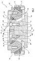
- Figure 6 shows a cross sectional view of a thrust bearing arrangement according to the present invention prior to bearing surface wear.
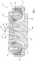
- Figure 7 shows the thrust bearing arrangement of Figure 6 but subject to bearing surface wear due to both an upward and downward directed axial thrust.
- a thrust bearing arrangement 13 comprising, generally, a bearing housing arrangement 14 configured to be mounted to a first given element and a bearing member 15 configured to be mounted to a second given element so as to couple together the two elements (for example a carriage and a bogie) in a similar manner to the prior art arrangement of Figures 1 to 5.
- the bearing housing arrangement 14 comprises an outer housing 14a incorporating a central base portion 16 and peripheral ring portion 17 which together define an annular recess 18.
- a central post 16a extending upwardly from the base portion 16 to approximately the same level as the upper edge of ring portion 17.
- Bearing member 15 is in the form of an annular bearing member having an outer bearing surface 21 and an inner bearing surface 22 which are both spherical, in the sense that they define at least a portion of the surface of an imaginary sphere, and which are also concentric with one another, in the sense that the centre of curvature of the associated imaginary spheres, indicated at 30 in Figure 6, are coincidental with one another.
- the annular bearing member 15 fits over the central hub portion 16 of the outer housing 14a to contiguously engage with the counter surface 20 of the liner 19.
- the counter surface 20, defined by the liner 19 represents an outer counter surface associated with the outer housing 14a.
- the bearing housing 6 arrangement 14 is also provided with an inner housing 14b in the general shape of a truncated upturned dome having an annular recess 23 configured to receive a further annular bearing liner 24 having a continuous counter surface 25 which is spherical, in the sense that it forms at least a portion of the surface of an imaginary sphere.
- the inner housing 14b has a cylindrical recess 28 at its lower end which receives the top section of the central 16a (see Figure 6). Thus the inner housing 14b is mounted on the central post 16a.
- two bores 29 are provided in the inner housing 14b which align with corresponding threaded holes 31 provided in the post 16a.
- Locking screws 32 pass through the bores 29 in the inner housing 14b and are screwed into the threaded holes 31 in the central post 16a.
- the locking screws 32 are countersunk into the body of the inner housing 14b so that the upper surface of the inner housing 14b has a flush profile.
- Adjustment screws 27 are mounted within screw threaded holes in the inner housing 14b opening on to the recess 23 such that the adjustment screws 27 may be screwed downwards to abut against the liner 24 and ensure a positive contiguous engagement of the counter surface of liner 24 with the inner bearing surface 22 of the bearing member 15.
- the counter surface defined by the liner 24 represents an inner bearing counter surface associated with the inner housing 14b.
- adjustment screws 27 may be progressively screwed downward to move the liner 24 towards the liner 19 and, as such, adjustment screws 27 and inner housing 14b effectively represent first and second complementary screw threaded members, associated respectively with the inner and outer counter surfaces, 20 and 25, which together form an adjustment means for adjusting the relative separation of the inner and outer counter surfaces (i.e. counter surfaces 25 and 20) to maintain both the inner and outer counter surfaces in contiguous engagement with the respective inner and outer bearing surfaces 22 and 21 of the bearing member 15.
- Wear characteristics of the bearing member 15 are selected so that the wear resistance of the bearing surfaces 21 and 22 are greater than the respective wear resistances of counter surfaces 20 and 25.
- wear resistances of the bearing surfaces 21 and 22 and counter surfaces 20 and 25 are selected so that wear occurring predominantly to counter surfaces 20 and 25 occurs at an identical rate; in particular, it is envisaged that, on the one hand, the wear resistance of the bearing surfaces 21 and 22 is selected to be identical and, on the other hand, the wear resistance of the counter surfaces 20 and 25 is also selected to be identical so that the two sets of bearing/counter surfaces are identical.
- the configuration of the thrust bearing arrangement is such that it can accommodate both a relative rotational motion of the bearing housing 14 and bearing member 15 about the central axis C, as well as a relative pivoting or yawing motion of the bearing housing 14 and bearing member 15 about the perpendicular axis D (running through the centre of curvature of bearing surfaces 20, 21, 22 and 25).
- the bearing member 15 will, essentially, retain its specific shape and, in particular, the spherical bearing surfaces 21 and 22 will, crucially, remain concentric with one another. Therefore, when the counter surface 25 of the liner 24 is re-engaged with the bearing surface 22 of the bearing member 15, each of the bearing surfaces 21, 22 and counter surfaces 20, 25 will, necessarily, still be concentric with one another, albeit about a new centre of curvature 28, axially offset by a distance 29 from the original centre of curvature 30 corresponding to the axial "drop" of the spherical bearing member 15 due to wear of the liner 19.
- the selected wear resistances of the bearing surfaces 21, 22 and counter surfaces 20, 25, in conjunction with the geometry of the bearing arrangement 13, ensure that the bearing arrangement 13 may still accommodate a relative rotation about the central axis C and relative yawing motion about the axis D (see Figure 6), without generation of an associated axial thrust, despite wear occurring at the counter surfaces, so that even where the bearing arrangement 13 is left “loose”, relative axial movement of the bearing member 15 and bearing housing 14 due to rotational and/or yawing motion is eliminated.
- the bearing housing may take any one of a number of possible forms and, in particular, is not limited to the particular configuration of bearing housing arrangement 14.
- the bearing housing might take the form of a housing arrangement similar to housing 6 shown in the prior art arrangement of Figures 1 to 5. That is, the housing arrangement may comprise an outer housing which is similar to outer housing 14a, in conjunction with an inner housing which is a "floating" housing similar to housing portion 6b of the prior art arrangement, with the two housings being secured to one another by means of a bolt and nut similar to securing bolt 7 and nut 9 of the prior art arrangement of Figures 1 to 5.
- the inner and outer counter surfaces 25 and 20, defined respectively by the liners 24 and 19 in the particular embodiment of Figures 6 and 7, could take any one of a number of alternative forms, provided only that they present a spherical counter surface to contiguously engage with the spherical bearing surfaces of the bearing member 15.
- the inner and outer counter surfaces may in fact be formed integrally with the inner and outer housing, for example the housings may be formed so as to have integral spherical counter surfaces, which could either define a "direct" (unlined) pair of counter surfaces or which could subsequently be lined directly with a conventional bearing liner.
- the adjustment means to move the inner and outer counter surfaces relative to one another could take any one of a number of alternative forms and, where the housing comprises a "floating" housing portion in similar manner to the prior art arrangement of Figures 1 to 5, it is envisaged that the securing bolt and nut used to secure the floating housing portion to the remainder of the bearing housing could themselves represent complementary screw threaded members which act as an adjustment means operable to move the inner and outer counter surfaces of the bearing housing relative to one another to ensure contiguous engagement of the counter surfaces with the respective bearing surfaces of the bearing member.
- the inner and outer counter surfaces may be resiliently biased towards one another, for example by a spring arrangement (not shown) such that any gap which tends to form between the bearing member and the counter surfaces is automatically “closed” by the spring arrangement, which acts to maintain the inner and outer counter surfaces in positive contiguous engagement with the bearing member without the need for manual adjustment.
Landscapes
- Engineering & Computer Science (AREA)
- General Engineering & Computer Science (AREA)
- Mechanical Engineering (AREA)
- Transportation (AREA)
- Support Of The Bearing (AREA)
- Pivots And Pivotal Connections (AREA)
- Rolling Contact Bearings (AREA)
Abstract
- i) a bearing member (15) having concentric spherical inner (22) and outer (21) bearing surfaces;
- ii) a spherical, thrust-bearing outer housing (14a) and a concentric, spherical, thrust-bearing inner housing (14b), the inner and outer bearing surfaces contiguously engaging with inner (25) and outer (20) counter surfaces associated with the inner and outer housings respectively; wherein
- iii) the wear resistance of the inner and outer bearing surfaces is greater than the wear resistance of the inner and outer counter surfaces respectively such that, in use of the arrangement, any wear between the bearing surfaces and counter surfaces occurs to the respective counter surfaces
Description
- The present invention relates to a thrust bearing arrangement for accommodating a bi-directional axial thrust and, in particular, a thrust bearing arrangement of the type generally used to couple two elements subject to relative rotation and yawing about a common axis, for example coupling a bogie to a passenger carriage.
- The axial thrust-bearing requirements of coupling bearings between the passenger carriages of trains, trams, buses and coaches are dependent upon the particular type of passenger carriages being coupled together in a given case. Thus, for a large number of passenger carriage types, the coupling bearing is only subjected to an axial thrust directed vertically downwardly and, as such, the coupling bearing between the carriages need only be able to accommodate a thrust in a vertically downward direction. Such coupling bearings need only have a single bearing surface capable of bearing a vertically downward axial thrust.
- However, in the case of certain types of carriages well known in the art, the associated coupling bearing is subjected to a bi-directional axial thrust, in particular a primary axial thrust in a vertical downward direction and a secondary axial thrust in a vertical upward direction, so that it is necessary to provide a coupling bearing which can accommodate both an upward axial thrust and a downward axial thrust.
- Figure 1 of the accompanying drawings shows a bi-directional axial thrust bearing arrangement known in the prior art for coupling a bogie to a passenger carriage (not shown). The prior art arrangement comprises a generally toroidal bearing
member 3, rigidly connected to a first connectingarm 1 from the bogie, having a first spherical bearingsurface 4 and a second spherical bearingsurface 5. The spherical bearingmember 3 is received within a bearing housing 6 which comprises afirst housing portion 6a rigidly connected to a second connectingarm 2 from the carriage and having a spherical bearing surface which is complementary to, and engages with, thebearing surface 4 of the spherical bearingmember 3. The bearing housing 6 also comprises a "floating"housing portion 6b having a spherical bearing surface which is complementary to, and engages with, the spherical bearingsurface 5 of the spherical bearingmember 3. Thehousing portion 6b is secured to the connectingarm 2 by means ofbolt 7 projecting down through aclearance hole 8 in the spherical bearingmember 3 andhousing portion 6a, and engaging with acomplementary nut 9. Thus, thebolt 7 andnut 9 act to secure both of thehousing portions bearing surfaces member 3. - It will be appreciated that, in the prior art arrangement shown in Figure 1, the coupling bearing between the connecting
arms arms case housing portion 6a andthrust bearing member 3 bear the axial thrust) as well as an upward axial direction (in which case spherical bearingmember 3 andhousing portion 6b bear the axial thrust). It will further be appreciated that relative rotational movement about the central axis A (Figure 1) can be accommodated by the coupling bearing. In addition, and with reference to Figure 2, it will be appreciated that the coupling bearing can also accommodate a relative yawing motion of the two connecting arms about an axis B passing through the centre of curvature of thebearing surfaces - It has been found that during operation of the prior art arrangement shown in Figure 1 over a given period of time, the
bolt 7 andnut 9 tend to become loose, thereby allowing relative axial acceleration between the connectingarms bolt 7 andnut 9 which, unless remedied, may result in deformation or even shearing of thesecuring bolt 7, with consequent coupling bearing failure. In order to overcome the problem of potential coupling bearing failure due to the securing bolt becoming loose, it has been normal practice to tighten the securingbolt 7 andnut 9 at regular intervals, thereby re-engaginghousing portions member 3 and thus eliminating the problem of relative axial acceleration of the connectingarms arms securing bolt 7 andnut 9, the securingbolt 7 andnut 9 are nevertheless still prone to deformation and possible shearing, with consequent coupling bearing failure; Thus, simply tightening the securingbolt 7 andnut 9 in the prior art arrangement shown in Figure 1 does not prevent unacceptable stresses being imposed on thesecuring bolt 7 andnut 9. - It is an object of the present invention to seek to provide an improved thrust bearing arrangement.
- It has now been found, in accordance with the present invention, that the above noted deficiencies in the prior art arrangement of Figure 1 of the accompanying drawings can be attributed to the specific relationship between the geometry of the bearing arrangement in conjunction with the selected wear characteristics of certain components within the arrangement.
- Thus, Figure 3 of the accompanying drawings shows the prior art arrangement of Figure 1 of the accompanying drawings after a given period of operation, during which time wear has occurred to the spherical bearing surface of the
housing portion 6a. Consequently, the spherical bearingmember 3 has dropped, to re-engage with the spherical bearing surface of thehousing portion 6a, thus tending to create agap 10 between thehousing portion 6b and thebearing surface 5 of the spherical bearingmember 3. It is noted that, in the momentary (schematic) position shown in Figure 3 of the accompanying drawings, wherein the housing portion is shown in its original position prior to wear, the centre of curvature of the spherical bearing surface of thehousing portion 6b is offset with respect to the centre of curvature of the spherical bearing surface of thehousing portion 6a, which has now effectively "dropped" downward due to wear by the spherical bearingmember 3. - Figure 4 shows the situation after the
housing portion 6b has also dropped to fill thegap 10 which is shown in Figure 3. In such a position, acorresponding gap 11 develops between thenut 9 and the connectingarm 2. However, because thehousing portion 6b has effectively dropped by an equal amount to the spherical bearingmember 3, which has in turn dropped by an equal amount to the "drop" in the spherical bearing surface of thehousing portion 6a, the centres of curvature of the spherical bearing surfaces of thehousing portions - Thus, successive wearing due to a downward axial thrust acts to maintain the centres of curvature of the spherical bearing surfaces of the
housing portion - However, over the same operating period, axial thrust in an upward direction will cause wear to the bearing surface 5 (due to the relative wear resistance of the spherical bearing
member 3 andhousing portion 6b) and, as shown in Figure 5, such wear to thebearing surface 5 will result in thehousing portion 6b dropping a further distance to once again re-engage with thebearing surface 5, with the result that an increasedgap 12 is formed between thenut 9 and the connectingarm 2. Critically, because the wear to thebearing surface 5 results in a drop of thehousing portion 6b, but no associated drop of the spherical bearingmember 3, the centres of curvature of the spherical bearing surfaces of thehousing portions - Referring again to Figure 5, it will be appreciated that, due to the formation of
gap 12, the connectingarms arm 2 with thenut 9 or, alternatively thebearing surface 5 with thehousing portion 6a. - In addition, and with reference to Figure 5, it can now be appreciated that wear occurring within the coupling bearing arrangement of Figure 1 of the accompanying drawings can result in a fundamental change in the bearing geometry of the arrangement, which alters the performance characteristics of the bearing. Thus, because the spherical bearing surfaces of the
housing portion 6a andhousing portion 6b are no longer concentric with one another, relative rotation or yawing motion of the connectingarms housing portion 6b, due to the spherical bearing member acting as a spherical "wedge". Thus, if the bearing is left loose, relative rotation or yawing of the connectingarms nut 9 andhousing portions 6a. Furthermore, if the securingbolt 7 andnut 9 are tightened to ensure engagement ofhousing portions surfaces member 3 then, although relative acceleration of the connectingarms bolt 7 andnut 9 which may lead to the aforementioned deformation or shearing of the securingbolt 7 and consequent coupling bearing failure. - According to the present invention there is provided a thrust bearing arrangement for withstanding a bi-directional axial thrust, the arrangement comprising a bearing member having concentric spherical inner and outer bearing surfaces; a spherical, thrust-bearing outer housing and a concentric, spherical, thrust-bearing inner housing, the inner and outer bearing surfaces contiguously engaging with inner and outer counter surfaces associated with the inner and outer housings respectively; wherein, the wear resistance of the inner and outer bearing surfaces is selected so as to be greater than the wear resistance of the inner and outer counter surfaces respectively such that, in use of the arrangement, wear between the bearing surfaces and counter surfaces occurs predominantly to the respective counter surfaces.
- Advantageously, a thrust bearing arrangement according to at least one of the inner and outer counter surfaces is defined by the respective housing.
- Preferably, at least one of the inner and outer counter surfaces is defined by a bearing liner attached to the respective housing.
- In a preferred embodiment, the thrust bearing arrangement is provided with adjustment means for adjusting the relative separation of the counter surfaces to maintain both of the inner and outer counter surfaces in contiguous engagement with the respective inner and outer bearing surfaces.
- In a yet further preferred embodiment, the adjustment means is in the form of a first screw threaded member associated with the inner counter surface and a second screw threaded member associated with the outer counter surface, the first screw threaded member being complementary, and engaging with a screw-threaded bore of the second screw threaded member.
- Preferably, the first screw-threaded member is in the form of an adjustment screw projecting at one end through a complementary screw-threaded bore in the second screw-threaded member, the projecting end of the adjustment screw being operably connected to one of said counter surfaces such that rotation of the adjustment screw advances said counter surface towards the other counter surface.
- Advantageously, the first screw-threaded member is in the form of an adjustment screw projecting through a clearance hole in each of the bearing housings and thrust bearing member, and the second screw-threaded member is in the form of an adjustment nut engaging with the projecting end of the adjustment screw opposite the screw head.
- Conveniently, the adjustment arrangement comprises a bias means to resiliently bias the inner and outer counter surfaces towards one another so as to ensure said maintenance of the inner and outer counter surfaces in contiguous engagement with the respective bearing surfaces.
conveniently, the outer housing has a base and a central post upstanding from the base, the central post being integrally formed with the housing, the inner housing being mounted on the central post, wherein there is further provided a number of threaded holes in the central post and a corresponding number of bores through the inner housing each to align with a corresponding threaded hole, and locking screw is fastened in each hole and bore to attach the inner housing to the central post. - Preferably, each locking screw is countersunk into the inner housing.
- Conveniently, at least one fixture is provided on the outer housing to mount the outer housing to a first element and wherein at least one fixture is provided on the spherical bearing member to mount the spherical bearing member to a second element.
- In a preferred embodiment, the first element is associated with a bogie of a vehicle and the second element is associated with a carriage of the vehicle.
- Figure 1 shows a cross sectional view of a thrust bearing arrangement according to the prior art in an operative position coupling together two loads.
- Figure 2 shows a cross sectional view of the prior art arrangement of Figure 1, illustrating how the arrangement accommodates a yawing motion between the two loads.
- Figure 3 shows a cross sectional view of the prior art arrangement of Figure 1 which schematically illustrates the initial effect of bearing surface wear due to a downwardly directed axial thrust.
- Figure 4 shows a cross sectional view of the partly worn bearing arrangement of Figure 3, illustrating the progressive effects of bearing surface wear due to a downwardly directed axial thrust.
- Figure 5 shows a cross sectional view of the partly worn arrangement of Figure 4, but further illustrating the effect of an additional bearing surface wear due to an upward axial thrust.
- Figure 6 shows a cross sectional view of a thrust bearing arrangement according to the present invention prior to bearing surface wear.
- Figure 7 shows the thrust bearing arrangement of Figure 6 but subject to bearing surface wear due to both an upward and downward directed axial thrust.
- Referring now to Figure 6, a thrust bearing
arrangement 13 is provided according to the present invention comprising, generally, a bearing housing arrangement 14 configured to be mounted to a first given element and abearing member 15 configured to be mounted to a second given element so as to couple together the two elements (for example a carriage and a bogie) in a similar manner to the prior art arrangement of Figures 1 to 5. - The bearing housing arrangement 14 comprises an
outer housing 14a incorporating acentral base portion 16 andperipheral ring portion 17 which together define anannular recess 18. Acentral post 16a extending upwardly from thebase portion 16 to approximately the same level as the upper edge ofring portion 17. Abearing liner 19, preferably in the form of a conventional preformed, thermoplastic lubricating liner, is mounted to therim portion 17 of theouter housing portion 14a and is configured to present a continuous,annular counter surface 20 which is spherical, in the sense that it forms at least a portion of the surface of an imaginary sphere. -
Bearing member 15 is in the form of an annular bearing member having anouter bearing surface 21 and an inner bearingsurface 22 which are both spherical, in the sense that they define at least a portion of the surface of an imaginary sphere, and which are also concentric with one another, in the sense that the centre of curvature of the associated imaginary spheres, indicated at 30 in Figure 6, are coincidental with one another. The annular bearingmember 15 fits over thecentral hub portion 16 of theouter housing 14a to contiguously engage with thecounter surface 20 of theliner 19. Thus, thecounter surface 20, defined by theliner 19, represents an outer counter surface associated with theouter housing 14a. - The bearing housing 6 arrangement 14 is also provided with an
inner housing 14b in the general shape of a truncated upturned dome having anannular recess 23 configured to receive a furtherannular bearing liner 24 having acontinuous counter surface 25 which is spherical, in the sense that it forms at least a portion of the surface of an imaginary sphere. - The
inner housing 14b has acylindrical recess 28 at its lower end which receives the top section of the central 16a (see Figure 6). Thus theinner housing 14b is mounted on thecentral post 16a. - In the example shown in Figure 6, two
bores 29 are provided in theinner housing 14b which align with corresponding threadedholes 31 provided in thepost 16a.Locking screws 32 pass through thebores 29 in theinner housing 14b and are screwed into the threadedholes 31 in thecentral post 16a. Preferably, thelocking screws 32 are countersunk into the body of theinner housing 14b so that the upper surface of theinner housing 14b has a flush profile. - Adjustment screws 27 (of which two are shown in Figure 6) are mounted within screw threaded holes in the
inner housing 14b opening on to therecess 23 such that the adjustment screws 27 may be screwed downwards to abut against theliner 24 and ensure a positive contiguous engagement of the counter surface ofliner 24 with theinner bearing surface 22 of the bearingmember 15. Thus, it will be appreciated that the counter surface defined by theliner 24 represents an inner bearing counter surface associated with theinner housing 14b. It is noted that the adjustment screws 27 may be progressively screwed downward to move theliner 24 towards theliner 19 and, as such, adjustment screws 27 andinner housing 14b effectively represent first and second complementary screw threaded members, associated respectively with the inner and outer counter surfaces, 20 and 25, which together form an adjustment means for adjusting the relative separation of the inner and outer counter surfaces (i.e. counter surfaces 25 and 20) to maintain both the inner and outer counter surfaces in contiguous engagement with the respective inner and outer bearing surfaces 22 and 21 of the bearingmember 15. - Wear characteristics of the bearing
member 15 are selected so that the wear resistance of the bearing surfaces 21 and 22 are greater than the respective wear resistances of counter surfaces 20 and 25. Preferably, wear resistances of the bearing surfaces 21 and 22 and counter surfaces 20 and 25 are selected so that wear occurring predominantly to countersurfaces - It will be appreciated, with reference to Figure 6, that the configuration of the thrust bearing arrangement is such that it can accommodate both a relative rotational motion of the bearing housing 14 and bearing
member 15 about the central axis C, as well as a relative pivoting or yawing motion of the bearing housing 14 and bearingmember 15 about the perpendicular axis D (running through the centre of curvature of bearingsurfaces - Referring now to Figure 7, the bearing arrangement is shown after operation over a given period of time, during which the arrangement has been subjected to an axial thrust both in a downward direction, tending to force the bearing
member 15 against theliner 19, and an upward direction, tending to force the bearingmember 15 against theliner 24. - It can be seen, from Figure 7, that, due to the relative wear resistances of bearing
surface 21 andcounter surface 20, subjecting the bearing arrangement to a downward axial thrust results in a progressive wearing of the liner 19 (as indicated by the dotted lines in Figure 7). In addition, it can be seen that, due to the relative wear resistances of bearingsurface 22 andcounter surface 25, subjecting the bearing arrangement to an upward axial thrust results in a progressive wearing of the liner 24 (indicated by the dotted lines in Figure 7). Specifically, it is to be noted that any wear between the bearing surfaces 21 and 22 and the respective inner and outer counter surfaces (20 and 25) occurs to the respective counter surface and not to the bearing surfaces 21 and 22 of the bearingmember 15. Thus, it will be appreciated that the bearingmember 15 will, essentially, retain its specific shape and, in particular, the spherical bearing surfaces 21 and 22 will, crucially, remain concentric with one another. Therefore, when thecounter surface 25 of theliner 24 is re-engaged with the bearingsurface 22 of the bearingmember 15, each of the bearing surfaces 21, 22 and counter surfaces 20, 25 will, necessarily, still be concentric with one another, albeit about a new centre ofcurvature 28, axially offset by adistance 29 from the original centre ofcurvature 30 corresponding to the axial "drop" of thespherical bearing member 15 due to wear of theliner 19. - Thus, the selected wear resistances of the bearing surfaces 21, 22 and counter surfaces 20, 25, in conjunction with the geometry of the bearing
arrangement 13, ensure that the bearingarrangement 13 may still accommodate a relative rotation about the central axis C and relative yawing motion about the axis D (see Figure 6), without generation of an associated axial thrust, despite wear occurring at the counter surfaces, so that even where the bearingarrangement 13 is left "loose", relative axial movement of the bearingmember 15 and bearing housing 14 due to rotational and/or yawing motion is eliminated. Consequently, it is possible to maintain theliner 19 andliner 24 in positive engagement with the bearingmember 15, by means of adjustment screws 27, thereby eliminating relative axial acceleration of the bearingmember 15 and bearing housing 14, whilst also preventing undesirable stress being imposed upon the securingbolt 26 in the case of relative rotation or yawing motion of the bearingmember 15 and housing 14. - It is envisaged that the bearing housing may take any one of a number of possible forms and, in particular, is not limited to the particular configuration of bearing housing arrangement 14. By way of another example, the bearing housing might take the form of a housing arrangement similar to housing 6 shown in the prior art arrangement of Figures 1 to 5. That is, the housing arrangement may comprise an outer housing which is similar to
outer housing 14a, in conjunction with an inner housing which is a "floating" housing similar tohousing portion 6b of the prior art arrangement, with the two housings being secured to one another by means of a bolt and nut similar to securingbolt 7 andnut 9 of the prior art arrangement of Figures 1 to 5. - Furthermore, it is envisaged that the inner and outer counter surfaces 25 and 20, defined respectively by the
liners member 15. Thus, the inner and outer counter surfaces may in fact be formed integrally with the inner and outer housing, for example the housings may be formed so as to have integral spherical counter surfaces, which could either define a "direct" (unlined) pair of counter surfaces or which could subsequently be lined directly with a conventional bearing liner. - Similarly, it is envisaged that the adjustment means to move the inner and outer counter surfaces relative to one another could take any one of a number of alternative forms and, where the housing comprises a "floating" housing portion in similar manner to the prior art arrangement of Figures 1 to 5, it is envisaged that the securing bolt and nut used to secure the floating housing portion to the remainder of the bearing housing could themselves represent complementary screw threaded members which act as an adjustment means operable to move the inner and outer counter surfaces of the bearing housing relative to one another to ensure contiguous engagement of the counter surfaces with the respective bearing surfaces of the bearing member.
- Indeed, in one particular preferred embodiment, it is envisaged that the inner and outer counter surfaces may be resiliently biased towards one another, for example by a spring arrangement (not shown) such that any gap which tends to form between the bearing member and the counter surfaces is automatically "closed" by the spring arrangement, which acts to maintain the inner and outer counter surfaces in positive contiguous engagement with the bearing member without the need for manual adjustment.
- When used in this specification and claims, the terms "comprises" and "comprising" and variations thereof mean that the specified features, steps or integers are included. The terms are not to be interpreted to exclude the presence of other features, steps or components.
Claims (12)
- A thrust bearing arrangement (13) for withstanding a bi-directional axial thrust, the arrangement (13) comprising:a bearing member (15) having concentric spherical inner (22) and outer (21) bearing surfaces;a spherical, thrust-bearing outer housing (14a) and a concentric, spherical, thrust-bearing inner housing (14b), the inner (22) and outer (21) bearing surfaces contiguously engaging with inner (25) and outer (20) counter surfaces associated with the inner (14b) and outer (14a) housings respectively;characterised in that:the wear resistance of the inner (22) and outer (21) bearing surfaces is selected so as to be greater than the wear resistance of the inner (25) and outer (20) counter surfaces respectively such that, in use of the arrangement (13), wear between the bearing surfaces (22,21) and counter surfaces (25,20) occurs predominantly to the respective counter surfaces (25,20).
- A thrust bearing arrangement (13) according to claim 1, wherein at least one of the inner (25) and outer (20) counter surfaces is defined by the respective housing (14b,14a).
- A thrust bearing arrangement (13) according to claim 1 wherein at least one of the inner (25) and outer (20) counter surfaces is defined by a bearing liner (24,19) attached to the respective housing (14b,14a).
- A thrust bearing arrangement (13) according to claims 1 to 3, wherein the arrangement is further provided with adjustment means (14b,26,27,32) for adjusting the relative separation of the counter surfaces (25,20) to maintain both of the inner (25) and outer (20) counter surfaces in contiguous engagement with the respective inner (22) and outer (21) bearing surfaces.
- A thrust bearing arrangement (13) according to claim 4, wherein the adjustment means is in the form of a first screw threaded member (27) associated with the inner counter surface (25) and a second screw threaded member (14b,26,32) associated with the outer counter surface (20), the first screw threaded member (27) being complementary, and engaging with, a screw-threaded bore of the second screw threaded member (14b,26,32).
- A thrust bearing arrangement (13) according to claim 5, wherein the first screw-threaded member is in the form of an adjustment screw (27) projecting at one end through a complementary screw-threaded bore in the second screw-threaded member (14b,26,32), the projecting end of the adjustment screw (27) being operably connected to one of said counter surfaces (20,25) such that rotation of the adjustment screw (27) advances said counter surface (20,25) towards the other counter surface (25,20).
- A thrust bearing arrangement (13) according to claim 5, wherein the first screw-threaded member is in the form of an adjustment screw projecting through a clearance hole in each of the bearing housings (14a,14b) and thrust bearing member (15), and the second screw-threaded member is in the form of an adjustment nut engaging with the projecting end of the adjustment screw opposite the screw head.
- A thrust bearing arrangement (13) according to any one of claims 4 to 7, wherein the adjustment arrangement comprises a bias means to resiliently bias the inner (25) and outer (20) counter surfaces towards one another so as to ensure said maintenance of the inner (25) and outer (20) counter surfaces in contiguous engagement with the respective bearing surfaces (21,22).
- A thrust bearing arrangement (13) according to any preceding claim, wherein the outer housing (14a) has a base (16) and a central post (16a) upstanding from the base (16), the central post (16a) being integrally formed with the housing (14a), the inner housing (14b) being mounted on the central post (16a), wherein there is further provided a number of threaded holes (31) in the central post (16a) and a corresponding number of bores through the inner housing (14b) each to align with a corresponding threaded hole (31), and locking screw (26) is fastened in each hole (31) and bore to attach the inner housing (14b) to the central post (16a).
- A thrust bearing arrangement (13) according to claim 9, wherein the or each locking screw (26) is countersunk into the inner housing (14b).
- A thrust bearing arrangement (13) according to any preceding claim, wherein at least one fixture is provided on the outer housing (14a) to mount the outer housing (14a) to a first element and wherein at least one fixture is provided on the spherical bearing member (15) to mount the spherical bearing member (15) to a second element.
- A thrust bearing arrangement (!3) according to claim 11, wherein the first element is associated with a bogie of a vehicle and the second element is associated with a carriage of the vehicle.
Applications Claiming Priority (1)
| Application Number | Priority Date | Filing Date | Title |
|---|---|---|---|
| GB0422564A GB2418964B (en) | 2004-10-11 | 2004-10-11 | Improvements in or relating to a thrust bearing arrangement |
Publications (3)
| Publication Number | Publication Date |
|---|---|
| EP1647725A2 true EP1647725A2 (en) | 2006-04-19 |
| EP1647725A3 EP1647725A3 (en) | 2006-04-26 |
| EP1647725B1 EP1647725B1 (en) | 2012-02-08 |
Family
ID=33443730
Family Applications (1)
| Application Number | Title | Priority Date | Filing Date |
|---|---|---|---|
| EP05021666A Expired - Lifetime EP1647725B1 (en) | 2004-10-11 | 2005-10-04 | Wear adjustable spherical thrust bearing arrangement for bi-directional axial loads for coupling a bogie to a passenger car |
Country Status (3)
| Country | Link |
|---|---|
| EP (1) | EP1647725B1 (en) |
| AT (1) | ATE544957T1 (en) |
| GB (1) | GB2418964B (en) |
Cited By (7)
| Publication number | Priority date | Publication date | Assignee | Title |
|---|---|---|---|---|
| CN105822665A (en) * | 2016-06-02 | 2016-08-03 | 株洲时代新材料科技股份有限公司 | Integrated metal joint bearing in low-floor vehicle fixed hinge and assembly method thereof |
| DE102016118023A1 (en) * | 2016-06-02 | 2017-12-07 | Zhuzhou Times New Material Technology Co., Ltd. | Connection method of a fixed hinge of a low-floor vehicle |
| CN107458407A (en) * | 2016-06-02 | 2017-12-12 | 株洲时代新材料科技股份有限公司 | Be articulated and connected method between a kind of low floor vehicle car body |
| CN107458410A (en) * | 2016-06-02 | 2017-12-12 | 株洲时代新材料科技股份有限公司 | Be articulated and connected method and articulated system between a kind of low floor vehicle car body |
| CN107458406A (en) * | 2016-06-02 | 2017-12-12 | 株洲时代新材料科技股份有限公司 | A kind of installation method of low floor vehicle rotating hinge and the transmission method of power |
| GB2603142A (en) * | 2021-01-27 | 2022-08-03 | Minebea Mitsumi Inc | Thrust bearing |
| EP4155099A1 (en) * | 2021-09-22 | 2023-03-29 | Wilhelm Schwarzmüller GmbH | Vehicle |
Families Citing this family (6)
| Publication number | Priority date | Publication date | Assignee | Title |
|---|---|---|---|---|
| CN102501859B (en) * | 2011-11-15 | 2014-06-25 | 长春广垠集团有限公司 | Power car for narrow gauge electric motor car |
| CN102501858B (en) * | 2011-11-15 | 2014-06-25 | 长春广垠集团有限公司 | Narrow-gauge electric motor car |
| CN107458408A (en) * | 2016-06-02 | 2017-12-12 | 株洲时代新材料科技股份有限公司 | Fixed hinge metal joint bearing and lower hold-down support attachment structure and attaching method thereof |
| CN107461404A (en) * | 2016-06-02 | 2017-12-12 | 株洲时代新材料科技股份有限公司 | Fixed hinge metal joint bearing and upper hold-down support attachment structure and attaching method thereof |
| CN107462417B (en) * | 2016-06-02 | 2019-07-26 | 株洲时代新材料科技股份有限公司 | A kind of low floor vehicle fixes the service life detection method of metal joint bearing in hinge |
| CN107458409B (en) * | 2016-06-02 | 2019-10-29 | 株洲时代新材料科技股份有限公司 | Be articulated and connected system and device between a kind of low floor vehicle car body |
Citations (1)
| Publication number | Priority date | Publication date | Assignee | Title |
|---|---|---|---|---|
| WO2003029065A1 (en) | 2001-09-28 | 2003-04-10 | Minebea Co. Ltd. | A thrust bearing |
Family Cites Families (8)
| Publication number | Priority date | Publication date | Assignee | Title |
|---|---|---|---|---|
| DE119922C (en) * | ||||
| US2828984A (en) * | 1955-03-16 | 1958-04-01 | Chow Ho | Linkage joints |
| GB1188599A (en) * | 1968-03-18 | 1970-04-22 | Moog Industries Inc | Self-adjusting Movable Joint Device |
| DE1916578B2 (en) * | 1969-04-01 | 1974-11-14 | Leopold F. 7000 Stuttgart Schmid | Steering linkages for automobiles |
| US4347014A (en) * | 1979-07-30 | 1982-08-31 | Gulf & Western Manufacturing Company | Hemispherical ball and socket joint |
| DE29603375U1 (en) * | 1996-02-24 | 1996-04-11 | SKF Gleitlager GmbH, 66346 Püttlingen | Dome joint |
| DE10139970A1 (en) * | 2001-08-14 | 2003-02-27 | Ina Schaeffler Kg | Linking unit for two adjacent body structures of multiple body rail vehicles, comprises two concentrically nested spherical pivot bearings whose inner elements are joined to different body structures |
| DE10138836A1 (en) * | 2001-08-14 | 2003-02-27 | Zf Lemfoerder Metallwaren Ag | ball joint |
-
2004
- 2004-10-11 GB GB0422564A patent/GB2418964B/en not_active Expired - Lifetime
-
2005
- 2005-10-04 EP EP05021666A patent/EP1647725B1/en not_active Expired - Lifetime
- 2005-10-04 AT AT05021666T patent/ATE544957T1/en active
Patent Citations (1)
| Publication number | Priority date | Publication date | Assignee | Title |
|---|---|---|---|---|
| WO2003029065A1 (en) | 2001-09-28 | 2003-04-10 | Minebea Co. Ltd. | A thrust bearing |
Cited By (12)
| Publication number | Priority date | Publication date | Assignee | Title |
|---|---|---|---|---|
| CN105822665A (en) * | 2016-06-02 | 2016-08-03 | 株洲时代新材料科技股份有限公司 | Integrated metal joint bearing in low-floor vehicle fixed hinge and assembly method thereof |
| DE102016118023A1 (en) * | 2016-06-02 | 2017-12-07 | Zhuzhou Times New Material Technology Co., Ltd. | Connection method of a fixed hinge of a low-floor vehicle |
| CN107458407A (en) * | 2016-06-02 | 2017-12-12 | 株洲时代新材料科技股份有限公司 | Be articulated and connected method between a kind of low floor vehicle car body |
| CN107458410A (en) * | 2016-06-02 | 2017-12-12 | 株洲时代新材料科技股份有限公司 | Be articulated and connected method and articulated system between a kind of low floor vehicle car body |
| CN107458406A (en) * | 2016-06-02 | 2017-12-12 | 株洲时代新材料科技股份有限公司 | A kind of installation method of low floor vehicle rotating hinge and the transmission method of power |
| CN107458406B (en) * | 2016-06-02 | 2019-04-30 | 株洲时代新材料科技股份有限公司 | A kind of installation method of low floor vehicle rotating hinge and the transmission method of power |
| CN107458407B (en) * | 2016-06-02 | 2019-04-30 | 株洲时代新材料科技股份有限公司 | Be articulated and connected method between a kind of low floor vehicle car body |
| CN107458410B (en) * | 2016-06-02 | 2019-07-02 | 株洲时代新材料科技股份有限公司 | Be articulated and connected method and articulated system between a kind of low floor vehicle car body |
| DE102016118023B4 (en) | 2016-06-02 | 2024-02-01 | Zhuzhou Times New Material Technology Co., Ltd. | Connection method of a fixed hinge of a low-floor vehicle and fixed hinge connecting device |
| GB2603142A (en) * | 2021-01-27 | 2022-08-03 | Minebea Mitsumi Inc | Thrust bearing |
| GB2603142B (en) * | 2021-01-27 | 2024-11-20 | Minebea Mitsumi Inc | Thrust bearing |
| EP4155099A1 (en) * | 2021-09-22 | 2023-03-29 | Wilhelm Schwarzmüller GmbH | Vehicle |
Also Published As
| Publication number | Publication date |
|---|---|
| GB0422564D0 (en) | 2004-11-10 |
| GB2418964A (en) | 2006-04-12 |
| EP1647725A3 (en) | 2006-04-26 |
| EP1647725B1 (en) | 2012-02-08 |
| GB2418964B (en) | 2007-01-10 |
| ATE544957T1 (en) | 2012-02-15 |
Similar Documents
| Publication | Publication Date | Title |
|---|---|---|
| EP1647725B1 (en) | Wear adjustable spherical thrust bearing arrangement for bi-directional axial loads for coupling a bogie to a passenger car | |
| AU605009B2 (en) | Railway car resilient side bearing | |
| EP3242834B1 (en) | Aircraft engine mount | |
| US8038162B2 (en) | Joint unit, preferably for mounting the chassis control arm of a motor vehicle | |
| US4800623A (en) | Automotive door hinge assembly with removable hinge wing | |
| US20230011564A1 (en) | Adjustable leveling kit and associated installation method | |
| EP1983202B1 (en) | A thrust bearing | |
| EP3066351B1 (en) | Bearing with anchor member | |
| JPS63103768A (en) | Steerable axle assembly | |
| JP2002115708A (en) | Vehicle connecting element having bolt portion and support ring and capable of loosening | |
| US3429598A (en) | Ball joint unit for steerable vehicle wheels | |
| US5810269A (en) | Gyratory crusher | |
| US5655848A (en) | Suspension ball joint | |
| CN107073557B (en) | One-piece self-locking nut | |
| US5509359A (en) | Pedestal liner system for locomotives | |
| EP2192312A2 (en) | A coupling bearing | |
| US9976599B2 (en) | Countersunk threaded bearing and method of installation | |
| US6149571A (en) | Centrifuge having a rotor with convex surface matching concave surface of nut for securing rotor on drive shaft | |
| CN118163830A (en) | A centering and resetting device for a coupler | |
| CN111059140A (en) | An anti-jamming hinge structure | |
| GB2424456A (en) | A thrust bearing arrangement | |
| CA2092635C (en) | Center plate friction reducing assembly | |
| US20210404508A1 (en) | Lock tight bolt-nut | |
| CN111455839A (en) | A force-limiting fuse and wind-resistant ball bearing | |
| US20180119730A1 (en) | Ball joint with a retainer/safety nut that prevents accidental separation of the ball stud and the socket |
Legal Events
| Date | Code | Title | Description |
|---|---|---|---|
| PUAI | Public reference made under article 153(3) epc to a published international application that has entered the european phase |
Free format text: ORIGINAL CODE: 0009012 |
|
| PUAL | Search report despatched |
Free format text: ORIGINAL CODE: 0009013 |
|
| AK | Designated contracting states |
Kind code of ref document: A2 Designated state(s): AT BE BG CH CY CZ DE DK EE ES FI FR GB GR HU IE IS IT LI LT LU LV MC NL PL PT RO SE SI SK TR |
|
| AX | Request for extension of the european patent |
Extension state: AL BA HR MK YU |
|
| AK | Designated contracting states |
Kind code of ref document: A3 Designated state(s): AT BE BG CH CY CZ DE DK EE ES FI FR GB GR HU IE IS IT LI LT LU LV MC NL PL PT RO SE SI SK TR |
|
| AX | Request for extension of the european patent |
Extension state: AL BA HR MK YU |
|
| RIN1 | Information on inventor provided before grant (corrected) |
Inventor name: HUELSEN, TOBIAS,NMB-MINEBEA UK LTD |
|
| 17P | Request for examination filed |
Effective date: 20061025 |
|
| AKX | Designation fees paid |
Designated state(s): AT BE BG CH CY CZ DE DK EE ES FI FR GB GR HU IE IS IT LI LT LU LV MC NL PL PT RO SE SI SK TR |
|
| 17Q | First examination report despatched |
Effective date: 20100806 |
|
| GRAP | Despatch of communication of intention to grant a patent |
Free format text: ORIGINAL CODE: EPIDOSNIGR1 |
|
| RIC1 | Information provided on ipc code assigned before grant |
Ipc: B61F 3/12 20060101ALI20110921BHEP Ipc: B61D 3/10 20060101ALI20110921BHEP Ipc: F16C 25/02 20060101ALI20110921BHEP Ipc: F16C 11/06 20060101AFI20110921BHEP Ipc: B61F 5/16 20060101ALI20110921BHEP |
|
| GRAS | Grant fee paid |
Free format text: ORIGINAL CODE: EPIDOSNIGR3 |
|
| GRAA | (expected) grant |
Free format text: ORIGINAL CODE: 0009210 |
|
| AK | Designated contracting states |
Kind code of ref document: B1 Designated state(s): AT BE BG CH CY CZ DE DK EE ES FI FR GR HU IE IS IT LI LT LU LV MC NL PL PT RO SE SI SK TR |
|
| RBV | Designated contracting states (corrected) |
Designated state(s): AT BE BG CH CY CZ DE DK EE ES FI FR GR HU IE IS IT LI LT LU LV MC NL PL PT RO SE SI SK TR |
|
| REG | Reference to a national code |
Ref country code: DE Ref legal event code: R081 Ref document number: 602005032570 Country of ref document: DE Owner name: MINEBEA MITSUMI INC., JP Free format text: FORMER OWNER: MINEBEA CO., LTD., NAGANO, JP |
|
| REG | Reference to a national code |
Ref country code: CH Ref legal event code: EP Ref country code: AT Ref legal event code: REF Ref document number: 544957 Country of ref document: AT Kind code of ref document: T Effective date: 20120215 |
|
| REG | Reference to a national code |
Ref country code: DE Ref legal event code: R096 Ref document number: 602005032570 Country of ref document: DE Effective date: 20120405 |
|
| REG | Reference to a national code |
Ref country code: NL Ref legal event code: VDEP Effective date: 20120208 |
|
| LTIE | Lt: invalidation of european patent or patent extension |
Effective date: 20120208 |
|
| PG25 | Lapsed in a contracting state [announced via postgrant information from national office to epo] |
Ref country code: LT Free format text: LAPSE BECAUSE OF FAILURE TO SUBMIT A TRANSLATION OF THE DESCRIPTION OR TO PAY THE FEE WITHIN THE PRESCRIBED TIME-LIMIT Effective date: 20120208 Ref country code: NL Free format text: LAPSE BECAUSE OF FAILURE TO SUBMIT A TRANSLATION OF THE DESCRIPTION OR TO PAY THE FEE WITHIN THE PRESCRIBED TIME-LIMIT Effective date: 20120208 Ref country code: IS Free format text: LAPSE BECAUSE OF FAILURE TO SUBMIT A TRANSLATION OF THE DESCRIPTION OR TO PAY THE FEE WITHIN THE PRESCRIBED TIME-LIMIT Effective date: 20120608 |
|
| PG25 | Lapsed in a contracting state [announced via postgrant information from national office to epo] |
Ref country code: FI Free format text: LAPSE BECAUSE OF FAILURE TO SUBMIT A TRANSLATION OF THE DESCRIPTION OR TO PAY THE FEE WITHIN THE PRESCRIBED TIME-LIMIT Effective date: 20120208 Ref country code: PT Free format text: LAPSE BECAUSE OF FAILURE TO SUBMIT A TRANSLATION OF THE DESCRIPTION OR TO PAY THE FEE WITHIN THE PRESCRIBED TIME-LIMIT Effective date: 20120608 Ref country code: BE Free format text: LAPSE BECAUSE OF FAILURE TO SUBMIT A TRANSLATION OF THE DESCRIPTION OR TO PAY THE FEE WITHIN THE PRESCRIBED TIME-LIMIT Effective date: 20120208 Ref country code: LV Free format text: LAPSE BECAUSE OF FAILURE TO SUBMIT A TRANSLATION OF THE DESCRIPTION OR TO PAY THE FEE WITHIN THE PRESCRIBED TIME-LIMIT Effective date: 20120208 Ref country code: PL Free format text: LAPSE BECAUSE OF FAILURE TO SUBMIT A TRANSLATION OF THE DESCRIPTION OR TO PAY THE FEE WITHIN THE PRESCRIBED TIME-LIMIT Effective date: 20120208 Ref country code: GR Free format text: LAPSE BECAUSE OF FAILURE TO SUBMIT A TRANSLATION OF THE DESCRIPTION OR TO PAY THE FEE WITHIN THE PRESCRIBED TIME-LIMIT Effective date: 20120509 |
|
| REG | Reference to a national code |
Ref country code: AT Ref legal event code: MK05 Ref document number: 544957 Country of ref document: AT Kind code of ref document: T Effective date: 20120208 |
|
| PG25 | Lapsed in a contracting state [announced via postgrant information from national office to epo] |
Ref country code: CY Free format text: LAPSE BECAUSE OF FAILURE TO SUBMIT A TRANSLATION OF THE DESCRIPTION OR TO PAY THE FEE WITHIN THE PRESCRIBED TIME-LIMIT Effective date: 20120208 |
|
| PG25 | Lapsed in a contracting state [announced via postgrant information from national office to epo] |
Ref country code: CZ Free format text: LAPSE BECAUSE OF FAILURE TO SUBMIT A TRANSLATION OF THE DESCRIPTION OR TO PAY THE FEE WITHIN THE PRESCRIBED TIME-LIMIT Effective date: 20120208 Ref country code: SI Free format text: LAPSE BECAUSE OF FAILURE TO SUBMIT A TRANSLATION OF THE DESCRIPTION OR TO PAY THE FEE WITHIN THE PRESCRIBED TIME-LIMIT Effective date: 20120208 Ref country code: SE Free format text: LAPSE BECAUSE OF FAILURE TO SUBMIT A TRANSLATION OF THE DESCRIPTION OR TO PAY THE FEE WITHIN THE PRESCRIBED TIME-LIMIT Effective date: 20120208 Ref country code: EE Free format text: LAPSE BECAUSE OF FAILURE TO SUBMIT A TRANSLATION OF THE DESCRIPTION OR TO PAY THE FEE WITHIN THE PRESCRIBED TIME-LIMIT Effective date: 20120208 Ref country code: DK Free format text: LAPSE BECAUSE OF FAILURE TO SUBMIT A TRANSLATION OF THE DESCRIPTION OR TO PAY THE FEE WITHIN THE PRESCRIBED TIME-LIMIT Effective date: 20120208 Ref country code: RO Free format text: LAPSE BECAUSE OF FAILURE TO SUBMIT A TRANSLATION OF THE DESCRIPTION OR TO PAY THE FEE WITHIN THE PRESCRIBED TIME-LIMIT Effective date: 20120208 |
|
| PG25 | Lapsed in a contracting state [announced via postgrant information from national office to epo] |
Ref country code: SK Free format text: LAPSE BECAUSE OF FAILURE TO SUBMIT A TRANSLATION OF THE DESCRIPTION OR TO PAY THE FEE WITHIN THE PRESCRIBED TIME-LIMIT Effective date: 20120208 Ref country code: IT Free format text: LAPSE BECAUSE OF FAILURE TO SUBMIT A TRANSLATION OF THE DESCRIPTION OR TO PAY THE FEE WITHIN THE PRESCRIBED TIME-LIMIT Effective date: 20120208 |
|
| PLBE | No opposition filed within time limit |
Free format text: ORIGINAL CODE: 0009261 |
|
| STAA | Information on the status of an ep patent application or granted ep patent |
Free format text: STATUS: NO OPPOSITION FILED WITHIN TIME LIMIT |
|
| 26N | No opposition filed |
Effective date: 20121109 |
|
| PG25 | Lapsed in a contracting state [announced via postgrant information from national office to epo] |
Ref country code: AT Free format text: LAPSE BECAUSE OF FAILURE TO SUBMIT A TRANSLATION OF THE DESCRIPTION OR TO PAY THE FEE WITHIN THE PRESCRIBED TIME-LIMIT Effective date: 20120208 |
|
| REG | Reference to a national code |
Ref country code: DE Ref legal event code: R097 Ref document number: 602005032570 Country of ref document: DE Effective date: 20121109 |
|
| PG25 | Lapsed in a contracting state [announced via postgrant information from national office to epo] |
Ref country code: ES Free format text: LAPSE BECAUSE OF FAILURE TO SUBMIT A TRANSLATION OF THE DESCRIPTION OR TO PAY THE FEE WITHIN THE PRESCRIBED TIME-LIMIT Effective date: 20120519 |
|
| PG25 | Lapsed in a contracting state [announced via postgrant information from national office to epo] |
Ref country code: MC Free format text: LAPSE BECAUSE OF NON-PAYMENT OF DUE FEES Effective date: 20121031 |
|
| REG | Reference to a national code |
Ref country code: CH Ref legal event code: PL |
|
| REG | Reference to a national code |
Ref country code: IE Ref legal event code: MM4A |
|
| PG25 | Lapsed in a contracting state [announced via postgrant information from national office to epo] |
Ref country code: IE Free format text: LAPSE BECAUSE OF NON-PAYMENT OF DUE FEES Effective date: 20121004 Ref country code: CH Free format text: LAPSE BECAUSE OF NON-PAYMENT OF DUE FEES Effective date: 20121031 Ref country code: BG Free format text: LAPSE BECAUSE OF FAILURE TO SUBMIT A TRANSLATION OF THE DESCRIPTION OR TO PAY THE FEE WITHIN THE PRESCRIBED TIME-LIMIT Effective date: 20120508 Ref country code: LI Free format text: LAPSE BECAUSE OF NON-PAYMENT OF DUE FEES Effective date: 20121031 |
|
| PG25 | Lapsed in a contracting state [announced via postgrant information from national office to epo] |
Ref country code: TR Free format text: LAPSE BECAUSE OF FAILURE TO SUBMIT A TRANSLATION OF THE DESCRIPTION OR TO PAY THE FEE WITHIN THE PRESCRIBED TIME-LIMIT Effective date: 20120208 |
|
| PG25 | Lapsed in a contracting state [announced via postgrant information from national office to epo] |
Ref country code: LU Free format text: LAPSE BECAUSE OF NON-PAYMENT OF DUE FEES Effective date: 20121004 |
|
| PG25 | Lapsed in a contracting state [announced via postgrant information from national office to epo] |
Ref country code: HU Free format text: LAPSE BECAUSE OF FAILURE TO SUBMIT A TRANSLATION OF THE DESCRIPTION OR TO PAY THE FEE WITHIN THE PRESCRIBED TIME-LIMIT Effective date: 20051004 |
|
| REG | Reference to a national code |
Ref country code: FR Ref legal event code: PLFP Year of fee payment: 12 |
|
| REG | Reference to a national code |
Ref country code: FR Ref legal event code: PLFP Year of fee payment: 13 |
|
| REG | Reference to a national code |
Ref country code: DE Ref legal event code: R082 Ref document number: 602005032570 Country of ref document: DE Representative=s name: BOEHMERT & BOEHMERT ANWALTSPARTNERSCHAFT MBB -, DE Ref country code: DE Ref legal event code: R081 Ref document number: 602005032570 Country of ref document: DE Owner name: MINEBEA MITSUMI INC., JP Free format text: FORMER OWNER: MINEBEA CO., LTD., NAGANO, JP |
|
| PGFP | Annual fee paid to national office [announced via postgrant information from national office to epo] |
Ref country code: DE Payment date: 20241031 Year of fee payment: 20 |
|
| PGFP | Annual fee paid to national office [announced via postgrant information from national office to epo] |
Ref country code: FR Payment date: 20241021 Year of fee payment: 20 |
|
| REG | Reference to a national code |
Ref country code: DE Ref legal event code: R071 Ref document number: 602005032570 Country of ref document: DE |