EP1647451A1 - Non-reversing short tape coil device - Google Patents
Non-reversing short tape coil device Download PDFInfo
- Publication number
- EP1647451A1 EP1647451A1 EP05077235A EP05077235A EP1647451A1 EP 1647451 A1 EP1647451 A1 EP 1647451A1 EP 05077235 A EP05077235 A EP 05077235A EP 05077235 A EP05077235 A EP 05077235A EP 1647451 A1 EP1647451 A1 EP 1647451A1
- Authority
- EP
- European Patent Office
- Prior art keywords
- housing
- spool
- wire
- teeth
- disposed
- Prior art date
- Legal status (The legal status is an assumption and is not a legal conclusion. Google has not performed a legal analysis and makes no representation as to the accuracy of the status listed.)
- Granted
Links
- 239000000463 material Substances 0.000 description 3
- 241001424392 Lucia limbaria Species 0.000 description 2
- 238000004519 manufacturing process Methods 0.000 description 2
- RYGMFSIKBFXOCR-UHFFFAOYSA-N Copper Chemical compound [Cu] RYGMFSIKBFXOCR-UHFFFAOYSA-N 0.000 description 1
- 229910052802 copper Inorganic materials 0.000 description 1
- 239000010949 copper Substances 0.000 description 1
- MPTQRFCYZCXJFQ-UHFFFAOYSA-L copper(II) chloride dihydrate Chemical compound O.O.[Cl-].[Cl-].[Cu+2] MPTQRFCYZCXJFQ-UHFFFAOYSA-L 0.000 description 1
- 238000012986 modification Methods 0.000 description 1
- 230000004048 modification Effects 0.000 description 1
- 230000000153 supplemental effect Effects 0.000 description 1
Images

Classifications
-
- B—PERFORMING OPERATIONS; TRANSPORTING
- B60—VEHICLES IN GENERAL
- B60R—VEHICLES, VEHICLE FITTINGS, OR VEHICLE PARTS, NOT OTHERWISE PROVIDED FOR
- B60R16/00—Electric or fluid circuits specially adapted for vehicles and not otherwise provided for; Arrangement of elements of electric or fluid circuits specially adapted for vehicles and not otherwise provided for
- B60R16/02—Electric or fluid circuits specially adapted for vehicles and not otherwise provided for; Arrangement of elements of electric or fluid circuits specially adapted for vehicles and not otherwise provided for electric constitutive elements
- B60R16/023—Electric or fluid circuits specially adapted for vehicles and not otherwise provided for; Arrangement of elements of electric or fluid circuits specially adapted for vehicles and not otherwise provided for electric constitutive elements for transmission of signals between vehicle parts or subsystems
- B60R16/027—Electric or fluid circuits specially adapted for vehicles and not otherwise provided for; Arrangement of elements of electric or fluid circuits specially adapted for vehicles and not otherwise provided for electric constitutive elements for transmission of signals between vehicle parts or subsystems between relatively movable parts of the vehicle, e.g. between steering wheel and column
-
- H—ELECTRICITY
- H01—ELECTRIC ELEMENTS
- H01R—ELECTRICALLY-CONDUCTIVE CONNECTIONS; STRUCTURAL ASSOCIATIONS OF A PLURALITY OF MUTUALLY-INSULATED ELECTRICAL CONNECTING ELEMENTS; COUPLING DEVICES; CURRENT COLLECTORS
- H01R35/00—Flexible or turnable line connectors, i.e. the rotation angle being limited
- H01R35/02—Flexible line connectors without frictional contact members
- H01R35/025—Flexible line connectors without frictional contact members having a flexible conductor wound around a rotation axis
Definitions
- the invention relates to an electrical connection between two parts rotatable relative to one another.
- a supplemental inflatable restraint or "SIR" coil is a continuous or permanent electrical conductive path between the bottom of the steering column and the steering wheel.
- a signal to inflate the SIR is communicated along the path.
- the prior art of SIR coils includes at least two different designs. In a first design, called a "clock spring," approximately seven to eight meters of wire are wrapped around the steering column. The wire is arranged to tighten or loosen as the steering wheel is rotated.
- a clock spring approximately seven to eight meters of wire are wrapped around the steering column. The wire is arranged to tighten or loosen as the steering wheel is rotated.
- the second design is called a reversing design.
- a reversing design is approximately 700 millimeters long.
- a single continuous tape is wrapped and unwrapped around the steering column.
- the tape forms an inner ring and an outer ring connected by a loop.
- the inner ring becomes longer and the outer ring becomes shorter, the position of the loop moving along a circular path defined by the steering column.
- the outer ring becomes longer and the inner ring becomes shorter.
- the fact that this design requires the loop portion also makes it necessary to use extremely small copper traces within the tape. These traces are difficult to manufacture and assemble.
- Another complication with using small copper traces is that a buss bar is required.
- the buss bar is connected to the traces and provides a more robust electrical connection.
- a terminal is crimped on the buss bar and external wires are connected to the terminal.
- the invention provides an apparatus, or coil device, including a housing and a spool disposed in the housing for rotation.
- the apparatus also includes a wire disposed in the housing and having a first end fixedly engaged with the housing and a second end fixedly engaged with the spool.
- the wire is moveable between a first configuration generally wound around the spool and a second configuration generally unwound with respect to the spool and arranged along an inner surface of the housing.
- the wire moves between the first and second configurations in response to relative rotation between the spool and the housing.
- the apparatus also includes at least one guide member disposed in the housing and movable along an arcuate path. The guide member moves in an opposite direction of rotation of the spool to guide movement of the wire between the spool and the housing.
- the present invention allows for a larger wire size in combination with a shorter length of wire.
- the wire can be sufficiently large to be directly connected to other wires without a buss bar.
- Another advantage of the present invention is that the present invention can be used with newer forms of tape. In particular, an extruded version of tape will not work in the prior art designs because the copper trace size is too large.
- An apparatus or coil device 10 includes a housing 12.
- the apparatus 10 also includes a spool or rotor 14 disposed in the housing 12 for rotation.
- the spool 14 rotates in the housing 12.
- the apparatus 10 also includes a wire 16 disposed in the housing 12.
- the wire 16 has first end or portion 18 fixedly engaged with the housing 12 and a second end or portion 20 fixedly engaged with the spool 14. In alternative embodiments of the invention, the wire 16 can extend beyond one or both of the spool 14 and the housing 12.
- the apparatus 10 also includes at least one guide member 22, 24, 26, 28, 30, 32 disposed in the housing 12. The at least one guide member 22, 24, 26, 28, 30, 32 moves along an arcuate path 34 in an opposite direction of rotation of the spool 14 to guide movement of the wire 16 between the spool 14 and the housing 12.
- the wire 16 extends along a spiral path around the spool 14 between the first and second ends 18, 20.
- the wire 16 is moveable between a first configuration generally unwound with respect to the spool 14 and arranged along an inner surface 74 of the housing 12 and a second configuration generally wound around the spool 14.
- the wire 16 moves between the first and second configurations in response to relative rotation between the spool 14 and the housing 12.
- the apparatus 10 is associated with a steering column of a vehicle.
- the at least one guide member 22, 24, 26, 28, 30, 32 is driven along an arcuate path 34 in a first angular direction 36 in response to rotation of the spool 14 in a second angular direction 38 opposite of the first angular direction 36.
- the spool 14 defines a first set of teeth 40 and the housing defines a fourth set of teeth 46.
- the guide member 22 includes a radially inward side 48 engaging both the spool 14 and the housing 12.
- the at least one guide member 22 defines a second set of teeth 42 disposed in meshing engagement with the first set of teeth 40 and a third set of teeth 44 spaced from the second set of teeth 42 and disposed in meshing engagement with the fourth set of teeth 46.
- the guide members 26 and 30 are structured similarly with respect to the guide member 22, each defining spaced sets of teeth at opposite ends. In alternative embodiments of the invention the guide members 22, 26, 30 could engage the spool 14 and housing 12 without teeth.
- the guide members 24, 28, 32 are also driven along the arcuate path 34 in the first angular direction 36 in response to rotation of the spool 14 in the second angular direction 38 opposite of the first angular direction 36.
- the guide members 24, 28, 32 do not engage the spool 14 or the housing and each has a substantially smooth outer surface.
- the guide members 22, 26, 30 are rotatably supported on posts 54, 58, 62 of a support member 50.
- the support member 50 includes a ring 52 axially aligned with the spool 14.
- the posts 54, 58, 62 are cantilevered from the ring 52.
- the support member also includes posts 56, 60, 64 cantilevered from the ring 52.
- the posts 56, 60, 64 rotatably support guide members 24, 28, 32.
- the guide members 22, 26, 30 are driven by the cooperation of the sets of gear teeth, such as teeth 40, 42, 44, 46, and drive the posts 54, 58, 62.
- the ring 52 and posts 56, 60, 64 are also driven in rotation along the arcuate path 34.
- the guide members 22, 24, 26, 28, 30, 32 are evenly spaced about the ring 52 and the spool 14.
- the guide members 22, 26, 30 are disposed further radially inward than the guide members 24, 28, 32 to engage the spool 14 and the housing 12.
- the ring 52 defines an outer edge 66 and an inner edge 68 and the guide members 22, 26, 30 are supported on a first set of posts 54, 58, 62 disposed closer to the inner edge 68.
- the guide members 24, 28, 32 are supported on a second set of posts 56, 60, 64 disposed closer to the outer edge 66.
- the radially spacing of the posts 54, 58, 62 and 56, 60, 64 enhances the guiding of the wire 16.
- the guide members 24, 28, 30 are disposed to guide or urge the wire 16 spirally outward against the surface 74 of the housing 12.
- the wire 16 is substantially fully arranged between the guide members 24, 28, 32 and the radially inwardly facing surface 74.
- the guide members 22, 26, 30 are disposed to guide or urge the wire 16 against an annular perimeter 76 of the spool 14.
- the wire 16 is substantially fully arranged between the first set of guide members 22, 26, 30 and the spool 14.
- the wire 16 extends along the spiral path between the first and second ends 18, 20, extending between only one of a first set of guide members 22, 26, 30 and only one of second set of guide members 24, 28, 32.
- the wire 16 defines a length between the first and second ends 18, 20.
- the length of the wire 16 can be less than the annular perimeter 76 of the spool 14 multiplied by twenty.
- the spool 14 is rotatable a predetermined number of 360° rotations and the length of the wire 16 can be substantially equal to the annular perimeter 76 multiplied by the predetermined number of 360° rotations.
- the wire 16 could be a "short-tape" design.
- a short tape design is preferrable to reduce material costs.
- the wire 16 can be both a short tape as well as non-reversing, as best shown in Figure 2.
- the wire 16 can be extruded, larger than copper traces in well known reversing, short tape structures.
- a locking device 82 locks the spool 14 with respect to a steering shaft 78.
- the housing 12 includes a plate 70 and a cover 72 releasibly engageable with one another. A portion of the locking device 82 extends through an aperture in the plate 70.
- the spool 14 rotates with the steering shaft 78.
- the steering shaft 78 defines a steering wheel supporting portion 80 for engaging a steering wheel of a vehicle.
Landscapes
- Engineering & Computer Science (AREA)
- Mechanical Engineering (AREA)
- Steering Controls (AREA)
- Storage Of Web-Like Or Filamentary Materials (AREA)
- Replacement Of Web Rolls (AREA)
Abstract
Description
- The invention relates to an electrical connection between two parts rotatable relative to one another.
- An electrical connection can be required between two parts that rotate relative to one another. For example, in a steering column for a vehicle, a supplemental inflatable restraint or "SIR" coil is a continuous or permanent electrical conductive path between the bottom of the steering column and the steering wheel. A signal to inflate the SIR is communicated along the path. The prior art of SIR coils includes at least two different designs. In a first design, called a "clock spring," approximately seven to eight meters of wire are wrapped around the steering column. The wire is arranged to tighten or loosen as the steering wheel is rotated. One of the main problems associated with this type of design is that the driver can feel the tension generated by the clock spring when turning in one direction. The second design is called a reversing design. A reversing design is approximately 700 millimeters long. Essentially, a single continuous tape is wrapped and unwrapped around the steering column. For example, the tape forms an inner ring and an outer ring connected by a loop. When the steering wheel is turned in one direction, the inner ring becomes longer and the outer ring becomes shorter, the position of the loop moving along a circular path defined by the steering column. When the steering column is turned in the other direction, the outer ring becomes longer and the inner ring becomes shorter. The fact that this design requires the loop portion also makes it necessary to use extremely small copper traces within the tape. These traces are difficult to manufacture and assemble. Another complication with using small copper traces is that a buss bar is required. The buss bar is connected to the traces and provides a more robust electrical connection. A terminal is crimped on the buss bar and external wires are connected to the terminal.
- The invention provides an apparatus, or coil device, including a housing and a spool disposed in the housing for rotation. The apparatus also includes a wire disposed in the housing and having a first end fixedly engaged with the housing and a second end fixedly engaged with the spool. The wire is moveable between a first configuration generally wound around the spool and a second configuration generally unwound with respect to the spool and arranged along an inner surface of the housing. The wire moves between the first and second configurations in response to relative rotation between the spool and the housing. The apparatus also includes at least one guide member disposed in the housing and movable along an arcuate path. The guide member moves in an opposite direction of rotation of the spool to guide movement of the wire between the spool and the housing.
- The present invention allows for a larger wire size in combination with a shorter length of wire. The wire can be sufficiently large to be directly connected to other wires without a buss bar. Another advantage of the present invention is that the present invention can be used with newer forms of tape. In particular, an extruded version of tape will not work in the prior art designs because the copper trace size is too large. These advantages will result in cost savings in material, manufacture and assembly.
- Other advantages of the present invention will be readily appreciated as the same becomes better understood by reference to the following detailed description when considered in connection with the accompanying drawings wherein:
- Figure 1 is an exploded view of the an exemplary embodiment of the invention in combination with a steering column for a vehicle;
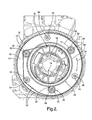
- Figure 2 is a partial cross-section taken generally along section lines 2 - 2 in Figure 1; and
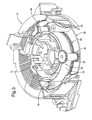
- Figure 3 is a cut--away perspective view of the exemplary embodiment of the invention.
- An apparatus or
coil device 10 includes ahousing 12. Theapparatus 10 also includes a spool orrotor 14 disposed in thehousing 12 for rotation. Thespool 14 rotates in thehousing 12. Theapparatus 10 also includes awire 16 disposed in thehousing 12. Thewire 16 has first end orportion 18 fixedly engaged with thehousing 12 and a second end orportion 20 fixedly engaged with thespool 14. In alternative embodiments of the invention, thewire 16 can extend beyond one or both of thespool 14 and thehousing 12. Theapparatus 10 also includes at least oneguide member housing 12. The at least oneguide member arcuate path 34 in an opposite direction of rotation of thespool 14 to guide movement of thewire 16 between thespool 14 and thehousing 12. - The
wire 16 extends along a spiral path around thespool 14 between the first andsecond ends wire 16 is moveable between a first configuration generally unwound with respect to thespool 14 and arranged along aninner surface 74 of thehousing 12 and a second configuration generally wound around thespool 14. Thewire 16 moves between the first and second configurations in response to relative rotation between thespool 14 and thehousing 12. In the exemplary embodiment of the invention, theapparatus 10 is associated with a steering column of a vehicle. - The at least one
guide member arcuate path 34 in a firstangular direction 36 in response to rotation of thespool 14 in a secondangular direction 38 opposite of the firstangular direction 36. For example, thespool 14 defines a first set ofteeth 40 and the housing defines a fourth set ofteeth 46. Theguide member 22 includes a radiallyinward side 48 engaging both thespool 14 and thehousing 12. The at least oneguide member 22 defines a second set ofteeth 42 disposed in meshing engagement with the first set ofteeth 40 and a third set ofteeth 44 spaced from the second set ofteeth 42 and disposed in meshing engagement with the fourth set ofteeth 46. When thespool 14 rotates in the secondangular direction 38, the cooperation between thegear teeth gear teeth guide member 22 in the firstangular direction 36. Theguide members guide member 22, each defining spaced sets of teeth at opposite ends. In alternative embodiments of the invention theguide members spool 14 and housing 12 without teeth. - The
guide members arcuate path 34 in the firstangular direction 36 in response to rotation of thespool 14 in the secondangular direction 38 opposite of the firstangular direction 36. In the exemplary embodiment of the invention, theguide members spool 14 or the housing and each has a substantially smooth outer surface. Theguide members posts support member 50. Thesupport member 50 includes aring 52 axially aligned with thespool 14. Theposts ring 52. The support member also includesposts ring 52. Theposts support guide members guide members teeth posts ring 52 andposts arcuate path 34. - In the exemplary embodiment of the invention, the
guide members ring 52 and thespool 14. Theguide members guide members spool 14 and thehousing 12. Thering 52 defines anouter edge 66 and aninner edge 68 and theguide members posts inner edge 68. Theguide members posts outer edge 66. The radially spacing of theposts wire 16. For example, theguide members wire 16 spirally outward against thesurface 74 of thehousing 12. In the first configuration, thewire 16 is substantially fully arranged between theguide members surface 74. Theguide members wire 16 against anannular perimeter 76 of thespool 14. In the second configuration, thewire 16 is substantially fully arranged between the first set ofguide members spool 14. In the exemplary embodiment, thewire 16 extends along the spiral path between the first and second ends 18, 20, extending between only one of a first set ofguide members guide members - The
wire 16 defines a length between the first and second ends 18, 20. The length of thewire 16 can be less than theannular perimeter 76 of thespool 14 multiplied by twenty. Also, thespool 14 is rotatable a predetermined number of 360° rotations and the length of thewire 16 can be substantially equal to theannular perimeter 76 multiplied by the predetermined number of 360° rotations. For example, in the exemplary steering column embodiment, thewire 16 could be a "short-tape" design. A short tape design is preferrable to reduce material costs. However, thewire 16 can be both a short tape as well as non-reversing, as best shown in Figure 2. Thewire 16 can be extruded, larger than copper traces in well known reversing, short tape structures. - In the exemplary embodiment of the invention, a
locking device 82 locks thespool 14 with respect to asteering shaft 78. Thehousing 12 includes aplate 70 and acover 72 releasibly engageable with one another. A portion of thelocking device 82 extends through an aperture in theplate 70. Thespool 14 rotates with the steeringshaft 78. The steeringshaft 78 defines a steeringwheel supporting portion 80 for engaging a steering wheel of a vehicle. - While the invention has been described with reference to an exemplary embodiment, it will be understood by those skilled in the art that various changes may be made and equivalents may be substituted for elements thereof without departing from the scope of the invention. In addition, many modifications may be made to adapt a particular situation or material to the teachings of the invention without departing from the essential scope thereof. Therefore, it is intended that the invention not be limited to the particular embodiment disclosed as the best mode contemplated for carrying out this invention, but that the invention will include all embodiments falling within the scope of the appended claims.
Claims (30)
- An apparatus (10) comprising:a housing (12);a spool (14) disposed in said housing (12) for rotation;a wire (16) disposed in said housing (12) and having a first end (18) fixedly engaged with said housing (12) and a second end (20) fixedly engaged with said spool (14); andat least one guide member (22, 24, 26, 28, 30, 32) disposed in said housing (12) and movable along an arcuate path (34) in an opposite direction of rotation of said spool (14) to guide movement of said wire (16) between said spool (14) and said housing (12).
- The apparatus (10) of claim 1 wherein said at least one guide member (22, 24, 26, 28, 30, 32) is driven along said arcuate path (34) in a first angular direction (36) in response to rotation of said spool (14) in a second angular direction (38) opposite of said first angular direction (36).
- The apparatus (10) of claim 1 wherein:said spool (14) defines a first set of teeth (40);said at least one guide member (22, 26, 30) defines a second set of teeth (42) disposed in meshing engagement with said first set of teeth (40) and a third set of teeth (44) spaced from said second set of teeth (42); andsaid housing (12) defines a fourth set of teeth (46) disposed in meshing engagement with said third set of teeth (44).
- The apparatus (10) of claim 1 wherein said at least one guide member (22, 26, 30) includes a radially inward side (48), said at least one guide member (22, 24, 26, 28, 30, 32) engaging both of said spool (14) and said housing (12) along said radially inward side (48).
- The apparatus (10) of claim 1 further comprising:a support member (50) having a ring (52) axially aligned with said spool (14) and at least one post (54, 56, 58, 60, 62, 64) cantilevered from said ring (52), said at least one guide member (22, 24, 26, 28, 30, 32) being rotatably supported by said at least one post (54, 56, 58, 60, 62, 64).
- The apparatus (10) of claim 5 wherein said at least one post (54, 56, 58, 60, 62, 64) further comprises:a plurality of posts (54, 56, 58, 60, 62, 64) cantilevered from said ring (52).
- The apparatus (10) of claim 6 wherein said at least one guide member (22, 24, 26, 28, 30, 32) further comprises:a plurality of guide members (22, 24, 26, 28, 30, 32) individually supported by one of said plurality of posts (54, 56, 58, 60, 62, 64) for movement along said arcuate path (34).
- The apparatus (10) of claim 7 wherein said plurality of posts (54, 56, 58, 60, 62, 64) are evenly spaced around said ring (52).
- The apparatus (10) of claim 7 wherein said ring (52) includes an outer edge (66) and an inner edge (68) and wherein said plurality of posts (54, 56, 58, 60, 62, 64) include a first set of posts (54, 58, 62) disposed closer to said inner edge (68) and a second set of posts (56, 60, 64) disposed closer to said outer edge (66).
- The apparatus (10) of claim 7 wherein said plurality of guide members (22, 24, 26, 28, 30, 32) includes a first set of guide members (22, 26, 30) each having an outer surface defining teeth (42, 44) and a second set of guide members (24, 28, 32) each having a substantially smooth outer surface.
- The apparatus (10) of claim 10 wherein said housing (12) further comprises:a plate (70); anda cover (72) releasibly engageable with said plate (70) and having an inner surface (74) defining radially outwardly facing teeth (46).
- The apparatus (10) of claim 1 wherein said wire (16) defines a length and said spool (14) defines an annular perimeter (76), said length being less than said annular perimeter (76) multiplied by twenty.
- The apparatus (10) of claim 12 wherein said spool (14) is further defined as being rotatable a predetermined number of 360° rotations and said length being substantially equal to said annular perimeter (76) multiplied by said predetermined number of 360° rotations.
- The apparatus (10) of claim 1 wherein said wire (16) is further defined as being extruded.
- The apparatus (10) of claim 1 wherein said wire (16) is further defined as extending out of said housing (12).
- The apparatus (10) of claim 1 wherein said wire (16) extends along a spiral path between said first and second ends (18, 20).
- The apparatus (10) of claim 16 wherein said wire (16) is non-reversing.
- An apparatus (10) comprising:a rotatable steering shaft (78) having a steering wheel engaging portion (80);a housing (12) encircling said steering shaft (78);a spool (14) disposed in said housing (12) for rotation with said steering shaft (78);a wire (16) disposed in said housing (12) and having a first end (18) fixedly engaged with said housing (12) and a second end (20) fixedly engaged with said spool (14); andat least one guide member (22, 24, 26, 28, 30, 32) disposed in said housing (12) and movable along an arcuate path (34) in an opposite direction of rotation as said spool (14) to guide movement of said wire (16) between said spool (14) and said housing (12).
- The apparatus (10) of claim 18 further comprising:a support member (50) encircling said steering shaft (78) and having a ring (52) with an outer edge (66) and an inner edge (68) and a first set of posts (54, 58, 62) cantilevered from said ring (52) and disposed closed to said inner edge (68) than said outer edge (66) and also having a second set of posts (56, 60, 64) cantilevered from said ring (52) and disposed closed to said outer edge (66) than said inner edge (68).
- The apparatus (10) of claim 19 wherein said at least one guide member (22, 24, 26, 28, 30, 32) further comprises:a first set of guide members (22, 26, 30) each having an outer surface defining teeth (42, 44) and rotatably supported on one of said first set of posts (54, 58, 62); anda second set of guide members (24, 28, 32) each having a substantially smooth outer surface and rotatably supported on one of said second set of posts (56, 60, 64).
- The apparatus (10) of claim 20 wherein said teeth (42, 44) are further defined as a second set of teeth (42) and a third set of teeth (44) axially spaced from one another.
- The apparatus (10) of claim 21 wherein said spool (14) defines a first set of teeth (40), said first set of teeth (40) disposed in meshing engagement with said second set of teeth (42)
- The apparatus (10) of claim 22 wherein said housing (12) defines a fourth set of teeth (46) disposed in meshing engagement with said third set of teeth (44), said fourth set of teeth (46) being radially outwardly facing.
- The apparatus (10) of claim 23 wherein said housing (12) defines a radially inwardly facing surface (74), said wire (16) being moveable from a first configuration substantially fully arranged between said second set of guide members (24, 28, 32) and said radially inwardly facing surface (74), and a second configuration substantially fully arranged between said first set of guide members (22, 26, 30) and said spool (14).
- The apparatus (10) of claim 24 wherein said wire (16) extends along a spiral path between said first and second ends (18, 20), extending between only one of said first set of guide members (22, 26, 30) and only one of second set of guide members (24, 28, 32).
- The apparatus (10) of claim 25 wherein said wire (16) is non-reversing.
- The apparatus (10) of claim 26 wherein said wire (16) is extruded.
- An electrical coil for a steering column of a vehicle comprising:a housing (12) encircling a steering shaft (78) of a vehicle;a spool (14) disposed in said housing (12) for rotation with the steering shaft (78); andan extruded wire (16) assembly having a first end (18) fixedly engaged with said housing (12) and a second end (20) fixedly engaged with said spool (14).
- The apparatus (10) of claim 28 wherein said extruded wire (16) assembly extends along a spiral path between said first and second ends (18, 20).
- The apparatus (10) of claim 29 wherein said extruded wire (16) assembly is non-reversing.
Applications Claiming Priority (1)
| Application Number | Priority Date | Filing Date | Title |
|---|---|---|---|
| US10/966,860 US7192293B2 (en) | 2004-10-15 | 2004-10-15 | Non-reversing short tape coil device |
Publications (2)
| Publication Number | Publication Date |
|---|---|
| EP1647451A1 true EP1647451A1 (en) | 2006-04-19 |
| EP1647451B1 EP1647451B1 (en) | 2008-04-16 |
Family
ID=35478329
Family Applications (1)
| Application Number | Title | Priority Date | Filing Date |
|---|---|---|---|
| EP05077235A Expired - Lifetime EP1647451B1 (en) | 2004-10-15 | 2005-10-03 | Non-reversing short tape coil device |
Country Status (4)
| Country | Link |
|---|---|
| US (1) | US7192293B2 (en) |
| EP (1) | EP1647451B1 (en) |
| AT (1) | ATE392341T1 (en) |
| DE (1) | DE602005006066T2 (en) |
Families Citing this family (3)
| Publication number | Priority date | Publication date | Assignee | Title |
|---|---|---|---|---|
| CA2792388C (en) | 2011-10-10 | 2020-01-14 | Wastequip, Llc | Hoist apparatus |
| JP6487224B2 (en) * | 2014-05-01 | 2019-03-20 | アルプスアルパイン株式会社 | Rotating connector |
| US11407436B2 (en) * | 2019-03-04 | 2022-08-09 | Byton North America Corporation | Steering wheel with fixed center |
Citations (4)
| Publication number | Priority date | Publication date | Assignee | Title |
|---|---|---|---|---|
| US4540223A (en) * | 1984-03-19 | 1985-09-10 | General Motors Corporation | Positive electrical connecting mechanism |
| US5171153A (en) * | 1990-10-24 | 1992-12-15 | Kabushiki Kaisha Tokai Rika Denki Seisakusho | Flat cable connector |
| US5561266A (en) * | 1993-09-06 | 1996-10-01 | Yazaki Corporation | Cable connector |
| US5637005A (en) * | 1993-05-31 | 1997-06-10 | Alps Electric Co., Ltd. | Clock spring connector |
Family Cites Families (90)
| Publication number | Priority date | Publication date | Assignee | Title |
|---|---|---|---|---|
| US3258727A (en) * | 1966-06-28 | Connector for high-current load device | ||
| US1366552A (en) * | 1917-02-12 | 1921-01-25 | Blackburn Patent Steering Whee | Steering-wheel |
| US1480656A (en) * | 1919-11-08 | 1924-01-15 | Blackburn Jasper | Electrical connection for automobiles |
| US1922493A (en) * | 1931-04-07 | 1933-08-15 | R M Company Inc | Steering wheel assembly |
| US2106925A (en) * | 1936-04-21 | 1938-02-01 | Sidney E Smith | Circuit controller for indicators |
| US2221409A (en) * | 1939-07-12 | 1940-11-12 | Gen Motors Corp | Horn button assembly |
| US2850715A (en) * | 1956-09-25 | 1958-09-02 | Gen Motors Corp | Contact and bearing assembly |
| NL122693C (en) * | 1959-01-02 | |||
| US3426308A (en) * | 1965-11-29 | 1969-02-04 | Bell Telephone Labor Inc | Rotatable connection |
| US3525536A (en) * | 1968-10-11 | 1970-08-25 | Eaton Yale & Towne | Vehicle safety apparatus positioned on steering wheel |
| US3597721A (en) * | 1969-09-29 | 1971-08-03 | Aeroflex Lab Inc | Multicircuit rotary electrical connector |
| NL7001611A (en) * | 1970-02-05 | 1971-08-09 | ||
| US3652971A (en) * | 1970-02-11 | 1972-03-28 | Kendick Mfg Co | Self-aligning slip ring capsule |
| US3712968A (en) * | 1970-05-05 | 1973-01-23 | Petri Lenkradwerk | Vehicle-steering wheel with horn-actuating baffle plate |
| US3657491A (en) * | 1970-05-28 | 1972-04-18 | Illinois Tool Works | Cord reel |
| US3691871A (en) * | 1970-06-25 | 1972-09-19 | Rolamite Inc | Rotary motion transmitting apparatus |
| DE2109463C2 (en) * | 1971-02-27 | 1972-12-07 | Ford Werke Ag | Steering wheel with safety air cushions, especially for motor vehicles |
| US3763455A (en) * | 1971-12-17 | 1973-10-02 | Gen Motors Corp | Electrically coupled steering column |
| JPS561275B2 (en) * | 1973-06-29 | 1981-01-12 | ||
| US3959608A (en) * | 1974-12-10 | 1976-05-25 | Allis-Chalmers Corporation | Reel arrangement for electric wiring |
| MX142898A (en) * | 1975-11-04 | 1981-01-14 | Schmidt Gmbh Karl | IMPROVEMENTS IN SANITATION INSTALLATION IN THE STEERING WHEELS OF AUTOMOTIVE VEHICLES |
| NL7700648A (en) * | 1977-01-21 | 1978-07-25 | Hazemeijer Bv | CONTACT DEVICE FOR TRANSMISSION OF ELECTRICAL CURRENT BETWEEN A FIXED CONTACT PART AND A MOVABLE CONTACT PART. |
| US4157854A (en) * | 1978-04-21 | 1979-06-12 | General Motors Corporation | Steering column electrical connector arrangement |
| US4246482A (en) * | 1978-06-19 | 1981-01-20 | Picker Corporation | Computed tomography method and apparatus |
| US4218073A (en) * | 1978-09-28 | 1980-08-19 | General Motors Corporation | Electrical connector arrangement for motor vehicle steering assembly |
| DE3100190C2 (en) * | 1980-01-11 | 1983-11-03 | Nissan Motor Co., Ltd., Yokohama, Kanagawa | Steering device for vehicles, in particular motor vehicles |
| JPS56116056U (en) * | 1980-02-04 | 1981-09-05 | ||
| US4417775A (en) * | 1980-11-26 | 1983-11-29 | Honda Giken Kogyo Kabushiki Kaisha | Electrical connector device |
| JPS57134350A (en) * | 1981-02-13 | 1982-08-19 | Honda Motor Co Ltd | Connector for steering of vehicle |
| DE3111922C1 (en) * | 1981-03-26 | 1982-11-11 | Daimler-Benz Ag, 7000 Stuttgart | Power line connector for rotatable components |
| US4547636A (en) * | 1982-07-28 | 1985-10-15 | Kabushiki Kaisha Tokai-Rika-Denki-Seisakusho | Slidable contact assembly |
| JPS6018434A (en) * | 1983-07-09 | 1985-01-30 | Toyoda Gosei Co Ltd | Relay mechanism for steering wheel |
| US4542858A (en) * | 1984-05-23 | 1985-09-24 | The United States Of America As Represented By The Administrator Of The National Aeronautics And Space Administration | Rotatable electric cable connecting system |
| US4607898A (en) * | 1984-11-13 | 1986-08-26 | Sheller-Globe Corporation | Spiral flex-circuit system for steering wheels |
| EP0192798B1 (en) * | 1985-03-01 | 1987-07-08 | Petri AG | Connector for the electrical junction of protecting devices by gas bag |
| EP0195831B1 (en) * | 1985-03-23 | 1989-06-07 | Petri AG | Adjusting device for a connector for current conduction of shock-preventing airbag-safety systems |
| DE3541287A1 (en) * | 1985-11-22 | 1987-05-27 | Kabelmetal Electro Gmbh | DEVICE FOR TRANSMITTING ELECTRICITY BETWEEN TWO RELATIVELY MOVABLE CONTACTS |
| US4753599A (en) * | 1986-03-31 | 1988-06-28 | Kabushiki Kaisha Tokai Rika Denki Seisakusho | Automotive steering assembly |
| JPH0629028B2 (en) * | 1986-04-07 | 1994-04-20 | 本田技研工業株式会社 | Neutral position display device for electrically conductive winding cable in steering handle for vehicle |
| US4744763A (en) * | 1986-04-15 | 1988-05-17 | Furukawa Electric Co., Ltd. | Connector device for a transmission line connecting two relatively rotating members |
| US4838803A (en) * | 1986-10-21 | 1989-06-13 | Alps Electric Co., Ltd. | Connector device |
| DE3641706A1 (en) * | 1986-12-06 | 1988-06-16 | Kabelmetal Electro Gmbh | DEVICE FOR TRANSMISSION OF CURRENT BETWEEN TWO RELATIVELY MOVABLE CONTACT POINTS |
| US4722690A (en) * | 1987-03-17 | 1988-02-02 | Methode Electronics, Inc. | Clock spring interconnector |
| US4824396A (en) * | 1987-05-27 | 1989-04-25 | Alps Electric Co., Ltd. | Electrical connection apparatus |
| DE3732124A1 (en) * | 1987-09-24 | 1989-04-13 | Kabelmetal Electro Gmbh | DEVICE FOR TRANSMITTING ELECTRICITY BETWEEN TWO RELATIVELY MOVABLE CONTACTS |
| JPH0429515Y2 (en) * | 1987-10-17 | 1992-07-16 | ||
| JPH0429516Y2 (en) * | 1987-11-09 | 1992-07-16 | ||
| US4844359A (en) * | 1987-12-10 | 1989-07-04 | Alps Electric Co., Ltd. | Cable reel |
| US4797109A (en) * | 1988-02-25 | 1989-01-10 | Methode Electronics, Inc. | Coiled wire interconnector |
| JPH0649485Y2 (en) * | 1988-03-14 | 1994-12-14 | 富士重工業株式会社 | Relay device for automobile steering |
| US4925122A (en) * | 1988-04-20 | 1990-05-15 | Alps Electric Co., Ltd. | Cable reel |
| JPH01161589U (en) * | 1988-04-30 | 1989-11-09 | ||
| JPH0454714Y2 (en) * | 1988-05-23 | 1992-12-22 | ||
| JPH082948Y2 (en) * | 1988-06-20 | 1996-01-29 | アルプス電気株式会社 | Connector device |
| DE3838114C1 (en) * | 1988-11-10 | 1989-12-21 | Kabelmetal Electro Gmbh, 3000 Hannover, De | |
| JPH0714304Y2 (en) * | 1988-12-21 | 1995-04-05 | アルプス電気株式会社 | Cable reel |
| JPH0720868Y2 (en) * | 1988-12-22 | 1995-05-15 | アルプス電気株式会社 | Cable reel |
| JPH02215071A (en) * | 1989-02-14 | 1990-08-28 | Furukawa Electric Co Ltd:The | Connector device |
| US4886460A (en) * | 1989-02-27 | 1989-12-12 | General Motors Corporation | Electrical connector assembly for a steering wheel occupant cushion restraint system |
| JPH0321544A (en) * | 1989-06-15 | 1991-01-30 | Daihatsu Motor Co Ltd | Wiring device |
| DE58907793D1 (en) * | 1989-09-12 | 1994-07-07 | Petri Ag | Power line connector for bridging wire breaks between mutually rotatable parts. |
| DE59007692D1 (en) * | 1990-01-13 | 1994-12-15 | Petri Ag | Connecting element for establishing an electrical connection between two parts which can be rotated relative to one another. |
| JP2529895Y2 (en) * | 1990-06-14 | 1997-03-19 | アルプス電気株式会社 | Cable reel |
| JPH0711425Y2 (en) * | 1990-08-08 | 1995-03-15 | 矢崎総業株式会社 | Brushless electrical signal transmitter |
| JPH0739190Y2 (en) * | 1990-10-02 | 1995-09-06 | 古河電気工業株式会社 | Rotating connector |
| JPH0711424Y2 (en) * | 1990-10-05 | 1995-03-15 | 古河電気工業株式会社 | Rotating connector |
| US5259775A (en) * | 1990-10-24 | 1993-11-09 | Kabushiki Kaisha Tokai Rika Denki Seisakusho | Flat cable connector |
| JP2575481Y2 (en) * | 1991-08-21 | 1998-06-25 | 古河電気工業株式会社 | Fixing structure of flat cable connection part in rotary connector |
| JP2538866Y2 (en) * | 1991-11-15 | 1997-06-18 | 古河電気工業株式会社 | Rotating connector |
| JP2826006B2 (en) * | 1991-12-13 | 1998-11-18 | アルプス電気株式会社 | Cable reel |
| DE4314648A1 (en) * | 1993-05-04 | 1994-11-10 | Kabelmetal Electro Gmbh | Method for producing a device for signal transmission between two end points |
| DE9312846U1 (en) * | 1993-08-27 | 1993-10-28 | Tünkers Maschinenbau GmbH, 40880 Ratingen | Vibrating bear for ramming and / or pulling rammed goods |
| JP2921733B2 (en) * | 1994-08-26 | 1999-07-19 | 矢崎総業株式会社 | Electrical connection between steering wheel and steering column |
| JPH0858602A (en) * | 1994-08-26 | 1996-03-05 | Yazaki Corp | Electrical connection device between steering wheel and steering column |
| JP2921734B2 (en) * | 1994-09-02 | 1999-07-19 | 矢崎総業株式会社 | Electrical connection between steering wheel and steering column |
| JP2981136B2 (en) * | 1994-12-22 | 1999-11-22 | 矢崎総業株式会社 | Electrical connection between steering wheel and steering column |
| DE19511654A1 (en) * | 1995-03-30 | 1996-10-02 | Alcatel Kabel Ag | Device for signal transmission between two end points |
| FR2738677B1 (en) * | 1995-09-07 | 1997-10-24 | Valeo Electronique | TURNING CONTACTOR WITH SHORT TAPE, ESPECIALLY FOR MOTOR VEHICLES |
| US5704633A (en) * | 1995-12-19 | 1998-01-06 | United Technologies Automotive Systems, Inc. | Modular clock spring arrangement |
| FR2753574B1 (en) * | 1996-09-16 | 1998-11-20 | Valeo Electronique | TURNING TAPE CONTACTOR, PARTICULARLY FOR MOTOR VEHICLES |
| JPH10172707A (en) * | 1996-12-13 | 1998-06-26 | Sumitomo Wiring Syst Ltd | High slip sound absorbing material and cable reel provided with the high slip sound absorbing material |
| EP0968101B1 (en) * | 1997-03-20 | 2001-10-31 | Delco Electronics Europe GmbH | Steering column assembly |
| US5988018A (en) * | 1997-11-14 | 1999-11-23 | Tolbert; Thomas R. | Mechanical wire stripper |
| US6236004B1 (en) * | 1998-03-20 | 2001-05-22 | Delco Electronics Europe Gmbh | Steering column assembly |
| DE19844869A1 (en) * | 1998-09-30 | 2000-05-11 | Alcatel Sa | Contact element for connecting a ribbon cable with round conductors and rotary connectors with such a contact element |
| FR2793752B1 (en) * | 1999-05-17 | 2001-06-29 | Lemforder Nacam Sa | ELECTRIC AND MECHANICAL STEERING DEVICE OF MOTOR VEHICLE |
| DE19948724A1 (en) * | 1999-10-09 | 2001-04-12 | Eaton Corp Eaton Ct Cleveland | Method for producing a housing for an electrical connection device between mutually rotatable parts |
| US6547689B2 (en) * | 2000-03-03 | 2003-04-15 | George Paul Baker, Jr. | Angular motion translator |
| US6254058B1 (en) * | 2000-04-25 | 2001-07-03 | Eaton Corporation | Spring returning a rotary valve with a differential planetary drive |
| US6617534B2 (en) * | 2001-05-07 | 2003-09-09 | Methode Electronics, Inc. | Combined detent plunger and moving contact |
-
2004
- 2004-10-15 US US10/966,860 patent/US7192293B2/en not_active Expired - Fee Related
-
2005
- 2005-10-03 DE DE602005006066T patent/DE602005006066T2/en not_active Expired - Fee Related
- 2005-10-03 EP EP05077235A patent/EP1647451B1/en not_active Expired - Lifetime
- 2005-10-03 AT AT05077235T patent/ATE392341T1/en not_active IP Right Cessation
Patent Citations (4)
| Publication number | Priority date | Publication date | Assignee | Title |
|---|---|---|---|---|
| US4540223A (en) * | 1984-03-19 | 1985-09-10 | General Motors Corporation | Positive electrical connecting mechanism |
| US5171153A (en) * | 1990-10-24 | 1992-12-15 | Kabushiki Kaisha Tokai Rika Denki Seisakusho | Flat cable connector |
| US5637005A (en) * | 1993-05-31 | 1997-06-10 | Alps Electric Co., Ltd. | Clock spring connector |
| US5561266A (en) * | 1993-09-06 | 1996-10-01 | Yazaki Corporation | Cable connector |
Also Published As
| Publication number | Publication date |
|---|---|
| US7192293B2 (en) | 2007-03-20 |
| ATE392341T1 (en) | 2008-05-15 |
| EP1647451B1 (en) | 2008-04-16 |
| US20060084306A1 (en) | 2006-04-20 |
| DE602005006066D1 (en) | 2008-05-29 |
| DE602005006066T2 (en) | 2009-05-14 |
Similar Documents
| Publication | Publication Date | Title |
|---|---|---|
| US4451105A (en) | Electrical connector device | |
| JPH0429516Y2 (en) | ||
| US4417775A (en) | Electrical connector device | |
| EP2816694B1 (en) | Flat cable winding device | |
| EP1650838B1 (en) | Rotary connector | |
| JPH0321544A (en) | Wiring device | |
| CN105813902A (en) | Rotary contactors for steering columns of motor vehicles | |
| EP0820125A2 (en) | Rotary connector | |
| KR0143943B1 (en) | Cable reel | |
| EP1647451B1 (en) | Non-reversing short tape coil device | |
| KR0155026B1 (en) | Clock spring connector | |
| DE69608537T2 (en) | SHORT TAPE ROTARY SWITCHES FOR MOTOR VEHICLES | |
| JP4891701B2 (en) | Rotating connector device | |
| KR101061989B1 (en) | Spacer and vehicle clock spring device including the spacer | |
| JP4355229B2 (en) | Rotating connector | |
| US6302716B1 (en) | Rotatable connector | |
| US6261112B1 (en) | Device for electrical connection between rotor and stator | |
| EP0758596A2 (en) | Electrical connecting device for connecting rotor with stator through cable | |
| JP2999627B2 (en) | Cable reel | |
| JPH0650283U (en) | Rotating connector | |
| JP3846100B2 (en) | Rotating connector | |
| KR100423338B1 (en) | clock spring of vehicles | |
| JP2702626B2 (en) | Cable reel | |
| JP4297295B2 (en) | Rotating connector | |
| JPH0754946Y2 (en) | Roll connector |
Legal Events
| Date | Code | Title | Description |
|---|---|---|---|
| PUAI | Public reference made under article 153(3) epc to a published international application that has entered the european phase |
Free format text: ORIGINAL CODE: 0009012 |
|
| AK | Designated contracting states |
Kind code of ref document: A1 Designated state(s): AT BE BG CH CY CZ DE DK EE ES FI FR GB GR HU IE IS IT LI LT LU LV MC NL PL PT RO SE SI SK TR |
|
| AX | Request for extension of the european patent |
Extension state: AL BA HR MK YU |
|
| 17P | Request for examination filed |
Effective date: 20061019 |
|
| 17Q | First examination report despatched |
Effective date: 20061127 |
|
| AKX | Designation fees paid |
Designated state(s): AT BE BG CH CY CZ DE DK EE ES FI FR GB GR HU IE IS IT LI LT LU LV MC NL PL PT RO SE SI SK TR |
|
| GRAP | Despatch of communication of intention to grant a patent |
Free format text: ORIGINAL CODE: EPIDOSNIGR1 |
|
| GRAS | Grant fee paid |
Free format text: ORIGINAL CODE: EPIDOSNIGR3 |
|
| GRAA | (expected) grant |
Free format text: ORIGINAL CODE: 0009210 |
|
| AK | Designated contracting states |
Kind code of ref document: B1 Designated state(s): AT BE BG CH CY CZ DE DK EE ES FI FR GB GR HU IE IS IT LI LT LU LV MC NL PL PT RO SE SI SK TR |
|
| REG | Reference to a national code |
Ref country code: CH Ref legal event code: EP |
|
| REG | Reference to a national code |
Ref country code: IE Ref legal event code: FG4D |
|
| REF | Corresponds to: |
Ref document number: 602005006066 Country of ref document: DE Date of ref document: 20080529 Kind code of ref document: P |
|
| PG25 | Lapsed in a contracting state [announced via postgrant information from national office to epo] |
Ref country code: SI Free format text: LAPSE BECAUSE OF FAILURE TO SUBMIT A TRANSLATION OF THE DESCRIPTION OR TO PAY THE FEE WITHIN THE PRESCRIBED TIME-LIMIT Effective date: 20080416 |
|
| NLV1 | Nl: lapsed or annulled due to failure to fulfill the requirements of art. 29p and 29m of the patents act | ||
| PG25 | Lapsed in a contracting state [announced via postgrant information from national office to epo] |
Ref country code: NL Free format text: LAPSE BECAUSE OF FAILURE TO SUBMIT A TRANSLATION OF THE DESCRIPTION OR TO PAY THE FEE WITHIN THE PRESCRIBED TIME-LIMIT Effective date: 20080416 Ref country code: BG Free format text: LAPSE BECAUSE OF FAILURE TO SUBMIT A TRANSLATION OF THE DESCRIPTION OR TO PAY THE FEE WITHIN THE PRESCRIBED TIME-LIMIT Effective date: 20080716 Ref country code: ES Free format text: LAPSE BECAUSE OF FAILURE TO SUBMIT A TRANSLATION OF THE DESCRIPTION OR TO PAY THE FEE WITHIN THE PRESCRIBED TIME-LIMIT Effective date: 20080727 Ref country code: FI Free format text: LAPSE BECAUSE OF FAILURE TO SUBMIT A TRANSLATION OF THE DESCRIPTION OR TO PAY THE FEE WITHIN THE PRESCRIBED TIME-LIMIT Effective date: 20080416 Ref country code: PT Free format text: LAPSE BECAUSE OF FAILURE TO SUBMIT A TRANSLATION OF THE DESCRIPTION OR TO PAY THE FEE WITHIN THE PRESCRIBED TIME-LIMIT Effective date: 20080916 |
|
| PG25 | Lapsed in a contracting state [announced via postgrant information from national office to epo] |
Ref country code: LV Free format text: LAPSE BECAUSE OF FAILURE TO SUBMIT A TRANSLATION OF THE DESCRIPTION OR TO PAY THE FEE WITHIN THE PRESCRIBED TIME-LIMIT Effective date: 20080416 Ref country code: PL Free format text: LAPSE BECAUSE OF FAILURE TO SUBMIT A TRANSLATION OF THE DESCRIPTION OR TO PAY THE FEE WITHIN THE PRESCRIBED TIME-LIMIT Effective date: 20080416 Ref country code: AT Free format text: LAPSE BECAUSE OF FAILURE TO SUBMIT A TRANSLATION OF THE DESCRIPTION OR TO PAY THE FEE WITHIN THE PRESCRIBED TIME-LIMIT Effective date: 20080416 |
|
| PG25 | Lapsed in a contracting state [announced via postgrant information from national office to epo] |
Ref country code: IS Free format text: LAPSE BECAUSE OF FAILURE TO SUBMIT A TRANSLATION OF THE DESCRIPTION OR TO PAY THE FEE WITHIN THE PRESCRIBED TIME-LIMIT Effective date: 20080816 |
|
| ET | Fr: translation filed | ||
| PG25 | Lapsed in a contracting state [announced via postgrant information from national office to epo] |
Ref country code: CZ Free format text: LAPSE BECAUSE OF FAILURE TO SUBMIT A TRANSLATION OF THE DESCRIPTION OR TO PAY THE FEE WITHIN THE PRESCRIBED TIME-LIMIT Effective date: 20080416 Ref country code: SE Free format text: LAPSE BECAUSE OF FAILURE TO SUBMIT A TRANSLATION OF THE DESCRIPTION OR TO PAY THE FEE WITHIN THE PRESCRIBED TIME-LIMIT Effective date: 20080716 Ref country code: DK Free format text: LAPSE BECAUSE OF FAILURE TO SUBMIT A TRANSLATION OF THE DESCRIPTION OR TO PAY THE FEE WITHIN THE PRESCRIBED TIME-LIMIT Effective date: 20080416 Ref country code: LT Free format text: LAPSE BECAUSE OF FAILURE TO SUBMIT A TRANSLATION OF THE DESCRIPTION OR TO PAY THE FEE WITHIN THE PRESCRIBED TIME-LIMIT Effective date: 20080416 |
|
| PLBE | No opposition filed within time limit |
Free format text: ORIGINAL CODE: 0009261 |
|
| STAA | Information on the status of an ep patent application or granted ep patent |
Free format text: STATUS: NO OPPOSITION FILED WITHIN TIME LIMIT |
|
| PG25 | Lapsed in a contracting state [announced via postgrant information from national office to epo] |
Ref country code: SK Free format text: LAPSE BECAUSE OF FAILURE TO SUBMIT A TRANSLATION OF THE DESCRIPTION OR TO PAY THE FEE WITHIN THE PRESCRIBED TIME-LIMIT Effective date: 20080416 Ref country code: BE Free format text: LAPSE BECAUSE OF FAILURE TO SUBMIT A TRANSLATION OF THE DESCRIPTION OR TO PAY THE FEE WITHIN THE PRESCRIBED TIME-LIMIT Effective date: 20080416 Ref country code: RO Free format text: LAPSE BECAUSE OF FAILURE TO SUBMIT A TRANSLATION OF THE DESCRIPTION OR TO PAY THE FEE WITHIN THE PRESCRIBED TIME-LIMIT Effective date: 20080416 |
|
| 26N | No opposition filed |
Effective date: 20090119 |
|
| PG25 | Lapsed in a contracting state [announced via postgrant information from national office to epo] |
Ref country code: EE Free format text: LAPSE BECAUSE OF FAILURE TO SUBMIT A TRANSLATION OF THE DESCRIPTION OR TO PAY THE FEE WITHIN THE PRESCRIBED TIME-LIMIT Effective date: 20080416 |
|
| PG25 | Lapsed in a contracting state [announced via postgrant information from national office to epo] |
Ref country code: MC Free format text: LAPSE BECAUSE OF NON-PAYMENT OF DUE FEES Effective date: 20081031 |
|
| PG25 | Lapsed in a contracting state [announced via postgrant information from national office to epo] |
Ref country code: IT Free format text: LAPSE BECAUSE OF FAILURE TO SUBMIT A TRANSLATION OF THE DESCRIPTION OR TO PAY THE FEE WITHIN THE PRESCRIBED TIME-LIMIT Effective date: 20080416 Ref country code: DE Free format text: LAPSE BECAUSE OF NON-PAYMENT OF DUE FEES Effective date: 20090501 |
|
| PG25 | Lapsed in a contracting state [announced via postgrant information from national office to epo] |
Ref country code: CY Free format text: LAPSE BECAUSE OF FAILURE TO SUBMIT A TRANSLATION OF THE DESCRIPTION OR TO PAY THE FEE WITHIN THE PRESCRIBED TIME-LIMIT Effective date: 20080416 |
|
| PG25 | Lapsed in a contracting state [announced via postgrant information from national office to epo] |
Ref country code: IE Free format text: LAPSE BECAUSE OF NON-PAYMENT OF DUE FEES Effective date: 20081003 |
|
| REG | Reference to a national code |
Ref country code: CH Ref legal event code: PL |
|
| PG25 | Lapsed in a contracting state [announced via postgrant information from national office to epo] |
Ref country code: HU Free format text: LAPSE BECAUSE OF FAILURE TO SUBMIT A TRANSLATION OF THE DESCRIPTION OR TO PAY THE FEE WITHIN THE PRESCRIBED TIME-LIMIT Effective date: 20081017 Ref country code: LU Free format text: LAPSE BECAUSE OF NON-PAYMENT OF DUE FEES Effective date: 20081003 |
|
| PG25 | Lapsed in a contracting state [announced via postgrant information from national office to epo] |
Ref country code: TR Free format text: LAPSE BECAUSE OF FAILURE TO SUBMIT A TRANSLATION OF THE DESCRIPTION OR TO PAY THE FEE WITHIN THE PRESCRIBED TIME-LIMIT Effective date: 20080416 |
|
| PG25 | Lapsed in a contracting state [announced via postgrant information from national office to epo] |
Ref country code: LI Free format text: LAPSE BECAUSE OF NON-PAYMENT OF DUE FEES Effective date: 20091031 Ref country code: GR Free format text: LAPSE BECAUSE OF FAILURE TO SUBMIT A TRANSLATION OF THE DESCRIPTION OR TO PAY THE FEE WITHIN THE PRESCRIBED TIME-LIMIT Effective date: 20080717 Ref country code: CH Free format text: LAPSE BECAUSE OF NON-PAYMENT OF DUE FEES Effective date: 20091031 |
|
| PG25 | Lapsed in a contracting state [announced via postgrant information from national office to epo] |
Ref country code: GB Free format text: LAPSE BECAUSE OF NON-PAYMENT OF DUE FEES Effective date: 20091003 |
|
| REG | Reference to a national code |
Ref country code: FR Ref legal event code: ST Effective date: 20110729 |
|
| PG25 | Lapsed in a contracting state [announced via postgrant information from national office to epo] |
Ref country code: FR Free format text: LAPSE BECAUSE OF NON-PAYMENT OF DUE FEES Effective date: 20081031 |