EP1645843B1 - Translation mechanism for opto-mechanical inspection - Google Patents
Translation mechanism for opto-mechanical inspection Download PDFInfo
- Publication number
- EP1645843B1 EP1645843B1 EP05077249.0A EP05077249A EP1645843B1 EP 1645843 B1 EP1645843 B1 EP 1645843B1 EP 05077249 A EP05077249 A EP 05077249A EP 1645843 B1 EP1645843 B1 EP 1645843B1
- Authority
- EP
- European Patent Office
- Prior art keywords
- translation stage
- flexible strip
- motion
- sensor
- coupled
- Prior art date
- Legal status (The legal status is an assumption and is not a legal conclusion. Google has not performed a legal analysis and makes no representation as to the accuracy of the status listed.)
- Expired - Lifetime
Links
Images


Classifications
-
- G—PHYSICS
- G01—MEASURING; TESTING
- G01B—MEASURING LENGTH, THICKNESS OR SIMILAR LINEAR DIMENSIONS; MEASURING ANGLES; MEASURING AREAS; MEASURING IRREGULARITIES OF SURFACES OR CONTOURS
- G01B5/00—Measuring arrangements characterised by the use of mechanical techniques
- G01B5/0002—Arrangements for supporting, fixing or guiding the measuring instrument or the object to be measured
- G01B5/0004—Supports
-
- G—PHYSICS
- G01—MEASURING; TESTING
- G01B—MEASURING LENGTH, THICKNESS OR SIMILAR LINEAR DIMENSIONS; MEASURING ANGLES; MEASURING AREAS; MEASURING IRREGULARITIES OF SURFACES OR CONTOURS
- G01B11/00—Measuring arrangements characterised by the use of optical techniques
- G01B11/02—Measuring arrangements characterised by the use of optical techniques for measuring length, width or thickness
- G01B11/06—Measuring arrangements characterised by the use of optical techniques for measuring length, width or thickness for measuring thickness ; e.g. of sheet material
- G01B11/0608—Height gauges
-
- G—PHYSICS
- G01—MEASURING; TESTING
- G01B—MEASURING LENGTH, THICKNESS OR SIMILAR LINEAR DIMENSIONS; MEASURING ANGLES; MEASURING AREAS; MEASURING IRREGULARITIES OF SURFACES OR CONTOURS
- G01B11/00—Measuring arrangements characterised by the use of optical techniques
- G01B11/24—Measuring arrangements characterised by the use of optical techniques for measuring contours or curvatures
- G01B11/25—Measuring arrangements characterised by the use of optical techniques for measuring contours or curvatures by projecting a pattern, e.g. one or more lines, moiré fringes on the object
- G01B11/2518—Projection by scanning of the object
- G01B11/2527—Projection by scanning of the object with phase change by in-plane movement of the patern
-
- G—PHYSICS
- G02—OPTICS
- G02B—OPTICAL ELEMENTS, SYSTEMS OR APPARATUS
- G02B21/00—Microscopes
- G02B21/24—Base structure
- G02B21/26—Stages; Adjusting means therefor
Definitions
- the invention relates to the optical inspection of a surface contour of an object using three-dimensional imaging techniques, and in particular to a mechanism used for moving a component of an opto-mechanical system relative to the object during such three-dimensional imaging.
- Inspection of semiconductor interconnects is especially crucial to ensure defect-free assembly of devices on printed circuit boards and flex circuits.
- two-dimensional (2-D) inspection of electronic components can ascertain if bumps or leads are missing or out of alignment
- three-dimensional (3-D) inspection can confirm that an electronic component is of a proper size and shape.
- 3-D inspection can also detect distortions of the surface contours of the substrate as aforesaid.
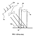
- FIG. 1 is a schematic illustration of an opto-mechanical inspection system of the prior art using a phase shifting technique with grating projection.
- a sinusoidal diffusion grating 10 comprising multiple equidistant and parallel lines or bars is frequently used for this purpose.
- Collimated light 12a incident on the sinusoidal grating 10 emerges as a modulated beam 12b such that its intensity has a unidirectional, sinusoidal spatial profile 14.
- This intensity-modulated beam 12b is incident over an object 16 to be inspected.
- the reflected beam 18 has a distorted intensity profile 20, the distortion being the result of the height variation of the object 16.
- the grating 10 is typically moved along its plane incrementally through a specific distance each time relative to the object 16.
- the direction of the motion is generally perpendicular to the orientation of the grating lines.
- images of the grating lines projected on the object are captured by a CCD camera that is positioned to view the distorted intensity profile 20 of the reflected beam 18.
- the grating 10 is moved through small incremental distances, typically fractions of a millimeter with accuracy of the order of 1-2 microns.
- an image of the pattern of the lines formed on the surface is captured by the CCD camera and recorded.
- a combination of these patterns gives rise to a depth profile along the surface of the object 16 so that its surface contour can be determined.
- Vision algorithms based on intensity and phase variations between these images are used to compute the height profile of the object.
- the motion of the grating has to be executed speedily and the grating positioned precisely at required locations in order to get accurate depth measurements while maintaining a high throughput.
- US patent 5.509.090 discloses an apparatus for moving an optical component of an opto-mechanical inspection system according to the preamble of claim 1.
- the relatively fixed support 57 is spaced from the translation stage 56, to which it is connected by flexible strips 58 and 59, in a direction perpendicular to the path of the projected light.
- the optical component to be moved may tend to rotate about the optical axis.
- the invention provides an apparatus for moving an optical component of an opto-mechanical inspection system relative to an object to be inspected as defined in claim 1.
- FIG. 2 is a side view of an opto-mechanical inspection system incorporating a displacement mechanism according to the preferred embodiment of the invention
- FIG. 3 is a sectional plan view of the opto-mechanical inspection system as viewed along line A-A' of FIG. 2
- the component to be moved such as an optical component in the form of a diffusion grating 10
- a translation stage comprising a lightweight movable frame 22.
- an object to be inspected may be mounted on the translation stage instead for relative motion between the object and the optical component, although this is less preferable.
- the grating lines are oriented in direction Y of the Cartesian reference frame XYZ as shown in FIG. 2 , and a light source (not shown) is operative to project incident light 12a, 12b in a direction parallel to direction Z.
- the diffusion grating 10 is oriented perpendicular to the incident light 12a, 12b and is configured to move along a plane that is substantially perpendicular to the direction of the said incident light.
- the movable frame 22 is suspended from a relatively fixed frame 24 using flexible strips of material or flexures 26 (shown in greater detail in FIG. 4 ).
- the flexures 26 are coupled to the movable frame 22 at one end and the fixed frame 24 at an opposite end.
- two flexures 26 separated by a suitable distance and aligned along the axis of motion of the movable frame 22 are used to support the movable frame 22 during its motion.
- the flexures 26 are preferably in the form of flat sheets, fractions of a millimeter thick. They are machined using either wire electro-discharge machining or photo-lithography or any other suitable method, yielding one or more flexing "arm' which bear the load of the moving member. They are preferably made from stainless steel or beryllium copper. Very high ratios of lateral stiffness to in-line stiffness can be realized using such flexures.
- Actuation of the mechanism using flexures is effected by a direct drive actuator such as a linear motor, and more preferably, a voice coil motor 28.
- the voice coil motor 28 could be of one of several possible topologies but in the present case it is cylindrical.
- the voice coil motor 28 is hereafter described with reference to FIG. 2 .
- a stationary magnet assembly of the voice coil motor 28 comprises an axially magnetized permanent magnet 28a in the shape of a ring, which is glued co-axially to an outer pole 28c.
- the permanent magnet 28a is made of a high energy density material such as neodymium ferrous boron.
- a ring shaped inner pole 28b is glued onto the magnet.
- the inner pole 28b and outer pole 28c are both made of magnetically permeable iron alloy.
- the annular air gap between the inner pole 28b and outer pole 28c contains a radial magnetic field.
- a coil 28d mounted on coil support 28e and appropriately positioned in the annular magnetic air gap is energized by an electric current, an axial force is induced on it because of the presence of the radial magnetic field.
- the direction of the current is reversed, the force on the coil 28d is also reversed.
- the above-described voice coil motor 28 is thus used to move and position the moving frame 22 and with it the grating 10.
- the movable frame 22 may either be coupled to the coil support 28e (as shown) or alternatively, to the magnet assembly. Alternative topologies of voice coil motors may be used in place of the voice coil motor 28 described above.
- the mechanism is intended to achieve a highly repeatable motion trajectory of the grating 10, very closely approximating straight line motion in a direction perpendicular to the grating lines and substantially co-planar with the grating itself, yielding a means whereby the image of the grating can be projected onto the object of interest (as schematically shown in FIG. 1 ) at slightly different locations at different times without manual intervention.
- the movable frame 22 is further coupled to a position sensor.
- a position sensor such as an LVDT (Linear Variable Differential Transducer) 30 provides position feedback on the movable frame 22 and grating 10 enabling the motor 28 to be operated in closed loop servo mode for very precise control over the axial position of the grating 10 mounted on the movable frame 22.
- the LVDT 30 comprises a stationary sensor head 30a, which usually comprises a coil winding assembly, and a moving ferromagnetic core 30b whereby to provide real-time feedback to the closed loop control system which controls the voice coil motor 28 and in turn, the position of the movable frame 22 to the desired precision.
- any other sensor such as a capacitive, inductive or optical sensor may be suitably used in place of the LVDT 30.
- the ferromagnetic core 30b of the LVDT 30 is affixed to the movable frame 22 in such a way that the core is nominally co-axial with the LVDT sensor head 30a.
- the entire LVDT assembly 30 is positioned to be substantially symmetric about the movable frame 22.
- FIG. 4 shows the flexure 26 with multiple flexing portions 26a spaced from one another wherein its flexing portions 26a are shaded. The remaining portions 26b and 26c do not flex and are used to mount the flexure onto the fixed frame 24 and movable frame 22 respectively using mounting holes 26d and clamping plates 32. The clamping plates 32 are shaped to fully cover the non-flexing portions 26b and 26c of the flexure 26.
- FIG. 5 shows the flexure bearing assembly consisting of a single flexure strip 26, each with two flexing portions 26a.
- the mutual coupling of the four flexing portions 26a of the flexure bearing assembly shown in FIG. 4 imparts to the entire assembly a high torsional rigidity.
- a very high lateral stiffness in the Y axis is imparted by orienting the planar surfaces of each sheet of flexure 26 substantially perpendicular to the axis of motion of the movable frame 22.
- this configuration keeps the in-line stiffness along the X axis much lower so as to facilitate motion in the X direction.
- the configuration thus imparts to the entire assembly a high torsional rigidity about all three axes X, Y and Z.
- the movable part of the mechanism is actuated by the voice coil motor 28 in such a way that the effective actuating force 34 is nominally symmetric with the movable frame and is substantially in line with the centre of gravity of the entire moving mass that comprises the movable frame 22.
- This avoids the generation of any considerable turning moment about the Z axis, which is perpendicular to the plane of the grating. This virtually eliminates "yaw" error deviation from rectilinear motion of the grating 10, which might otherwise adversely affect the imaging process.
- a high precision motion stage has been disclosed in the preferred embodiment of the invention which is used to accurately position a component of an opto-mechanical inspection system, such as an optical diffusion grating.
- the motion stage preferably uses a voice coil motor as a direct drive actuator.
- use of flexure bearings ensures freedom from friction/stiction thus facilitating high resolution and repeatability without any wear that accompanies and adversely affects conventional bearings.
Landscapes
- Physics & Mathematics (AREA)
- General Physics & Mathematics (AREA)
- Engineering & Computer Science (AREA)
- Computer Vision & Pattern Recognition (AREA)
- Chemical & Material Sciences (AREA)
- Analytical Chemistry (AREA)
- Optics & Photonics (AREA)
- Length Measuring Devices By Optical Means (AREA)
- Investigating Materials By The Use Of Optical Means Adapted For Particular Applications (AREA)
- Reciprocating, Oscillating Or Vibrating Motors (AREA)
- Container, Conveyance, Adherence, Positioning, Of Wafer (AREA)
Description
- The invention relates to the optical inspection of a surface contour of an object using three-dimensional imaging techniques, and in particular to a mechanism used for moving a component of an opto-mechanical system relative to the object during such three-dimensional imaging.
- In the semiconductor manufacturing and assembly industry, it is sometimes necessary to visually inspect the surfaces of electronic components to ensure that there are no defects. Machines in the industry often use computerized vision systems for various purposes such as for monitoring processes and inspecting finished or intermediate product outputs from individual machines. In one instance, after molding to form a semiconductor package, it is prudent to inspect the surface of the package for cavities or unacceptable unevenness of the surface. In such instances, three-dimensional optical inspection systems would be most ideal because of the ability to detect depth within the optical system's field of vision.
- Inspection of semiconductor interconnects is especially crucial to ensure defect-free assembly of devices on printed circuit boards and flex circuits. Before assembly of semiconductor devices, two-dimensional (2-D) inspection of electronic components can ascertain if bumps or leads are missing or out of alignment, while three-dimensional (3-D) inspection can confirm that an electronic component is of a proper size and shape. 3-D inspection can also detect distortions of the surface contours of the substrate as aforesaid.
- Among the several non-contact, optical methods of obtaining 3-D images of objects, one involves the projection of a grating image onto the object under scrutiny.
FIG. 1 is a schematic illustration of an opto-mechanical inspection system of the prior art using a phase shifting technique with grating projection. A sinusoidal diffusion grating 10 comprising multiple equidistant and parallel lines or bars is frequently used for this purpose. Collimatedlight 12a incident on thesinusoidal grating 10 emerges as a modulatedbeam 12b such that its intensity has a unidirectional, sinusoidalspatial profile 14. This intensity-modulatedbeam 12b is incident over anobject 16 to be inspected. Thereflected beam 18 has a distortedintensity profile 20, the distortion being the result of the height variation of theobject 16. Thegrating 10 is typically moved along its plane incrementally through a specific distance each time relative to theobject 16. The direction of the motion is generally perpendicular to the orientation of the grating lines. Between successive strokes, images of the grating lines projected on the object are captured by a CCD camera that is positioned to view thedistorted intensity profile 20 of thereflected beam 18. - In general, the
grating 10 is moved through small incremental distances, typically fractions of a millimeter with accuracy of the order of 1-2 microns. At each position of thegrating 10, an image of the pattern of the lines formed on the surface is captured by the CCD camera and recorded. A combination of these patterns gives rise to a depth profile along the surface of theobject 16 so that its surface contour can be determined. Vision algorithms based on intensity and phase variations between these images are used to compute the height profile of the object. With the demands of modern-day semiconductor manufacturing and assembly systems, the motion of the grating has to be executed speedily and the grating positioned precisely at required locations in order to get accurate depth measurements while maintaining a high throughput. - In order to achieve the said speed and accuracy, the movement of the grating should preferably be actuated by a mechanism that is highly precise. Prior art apparatus for displacement of optical components are flawed in this respect. For example,
US Patent Publication no. 2004/28333 for "Tunable Optical Filter" teaches the use of an actuation means including a threaded drive shaft whose thread has leading and trailing thread faces. Threaded nut regions resiliently engage the thread faces of the drive shaft, the threaded nut regions being in communication with a filter plate for moving the filter plate relative to a radiation beam in response to rotation of the drive shaft member relative to the threaded nut regions. The drive shaft member is connected to a stepper motor, d.c. motor or linear motor for controllably rotating the drive shaft. In another prior art example,US Patent no. 5,307,152 for a "Moiré Inspection System" discloses the mounting of a grating on a translation stage that comprises a precision motorized micrometer that is used to drive the translation stage. - These prior art examples use motors that basically convert rotary motion to linear motion to control translation of the grating and are insufficiently precise for higher performance requirements, especially as there are a number of disadvantages associated with their designs. For instance, for practical reasons, a rotating screw and an associated nut that is movable on the screw cannot be coupled too tightly together so as to allow one to move relative to the other. Therefore, gaps exist between corresponding threads of the screw and nut that can give rise to backlash and hysteresis problems, especially during fast motion involving a change of direction of motion. Furthermore, the gap often gives rise to an offset between rotary and corresponding linear motion, which retards its ability to execute quick and accurate motion.
-
US patent 5.509.090 discloses an apparatus for moving an optical component of an opto-mechanical inspection system according to the preamble of claim 1. In the apparatus shown infig.5 of this document, the relatively fixed support 57 is spaced from the translation stage 56, to which it is connected by flexible strips 58 and 59, in a direction perpendicular to the path of the projected light. As a result, the optical component to be moved may tend to rotate about the optical axis. - Therefore, it would be desirable to employ a displacement mechanism for the optical grating that avoids some of the above problems with the said prior art mechanisms. Furthermore, it would also be desirable to introduce a frictionless and wear-free structural support for sliding displacement of the grating. Conventional supports utilize roller bearings that encounter wear while rolling over surfaces and they lack accuracy and repeatability because of friction from contact with the surfaces on which they slide. It would be advantageous to implement a new support mechanism that has higher accuracy and repeatability. Flexures are especially suited for these purposes due to the excellent inherent repeatability of their motion trajectory devoid of friction and wear.
- It is therefore an object of the invention to seek to provide an improved translation mechanism that is usable to move a component of an opto-mechanical inspection system relative to an object to be inspected more precisely and repeatably as compared to the aforesaid prior art mechanisms.
- Accordingly, the invention provides an apparatus for moving an optical component of an opto-mechanical inspection system relative to an object to be inspected as defined in claim 1.
- It would be convenient hereinafter to describe the invention in greater detail by reference to the accompanying drawings which illustrate one embodiment of the invention. The particularity of the drawings and the related description is not to be understood as superseding the generality of the broad identification of the invention as defined by the claims.
- An example of a preferred embodiment of an apparatus in accordance with the invention will now be described with reference to the accompanying drawings, in which:
-
FIG. 1 is a schematic illustration of an opto-mechanical inspection system of the prior art using a phase shift principle with grating projection; -
FIG. 2 is a side view of an opto-mechanical inspection system incorporating a displacement mechanism according to the preferred embodiment of the invention; -
FIG. 3 is a sectional plan view of the opto-mechanical inspection system as viewed along line A-A' ofFIG. 2 ; -
FIG. 4 is an isometric view of the flexure support system according to the preferred embodiment of the invention; and -
FIG. 5 is a side view of the flexure support system looking from direction B ofFIG. 4 . - A preferred embodiment of the present invention will be described with reference to
FIGS. 2 and 3. FIG. 2 is a side view of an opto-mechanical inspection system incorporating a displacement mechanism according to the preferred embodiment of the invention, whereasFIG. 3 is a sectional plan view of the opto-mechanical inspection system as viewed along line A-A' ofFIG. 2 . The component to be moved, such as an optical component in the form of a diffusion grating 10, is suitably mounted and affixed onto a translation stage comprising a lightweightmovable frame 22. It is also conceivable that an object to be inspected may be mounted on the translation stage instead for relative motion between the object and the optical component, although this is less preferable. - In the described embodiment, the grating lines are oriented in direction Y of the Cartesian reference frame XYZ as shown in
FIG. 2 , and a light source (not shown) is operative to projectincident light diffusion grating 10 is oriented perpendicular to theincident light movable frame 22 is suspended from a relatively fixedframe 24 using flexible strips of material or flexures 26 (shown in greater detail inFIG. 4 ). Theflexures 26 are coupled to themovable frame 22 at one end and thefixed frame 24 at an opposite end. Preferably, twoflexures 26 separated by a suitable distance and aligned along the axis of motion of themovable frame 22 are used to support themovable frame 22 during its motion. - The
flexures 26 are preferably in the form of flat sheets, fractions of a millimeter thick. They are machined using either wire electro-discharge machining or photo-lithography or any other suitable method, yielding one or more flexing "arm' which bear the load of the moving member. They are preferably made from stainless steel or beryllium copper. Very high ratios of lateral stiffness to in-line stiffness can be realized using such flexures. - Actuation of the mechanism using flexures is effected by a direct drive actuator such as a linear motor, and more preferably, a
voice coil motor 28. Thevoice coil motor 28 could be of one of several possible topologies but in the present case it is cylindrical. Thevoice coil motor 28 is hereafter described with reference toFIG. 2 . A stationary magnet assembly of thevoice coil motor 28 comprises an axially magnetizedpermanent magnet 28a in the shape of a ring, which is glued co-axially to anouter pole 28c. Thepermanent magnet 28a is made of a high energy density material such as neodymium ferrous boron. A ring shapedinner pole 28b is glued onto the magnet. Theinner pole 28b andouter pole 28c are both made of magnetically permeable iron alloy. - The annular air gap between the
inner pole 28b andouter pole 28c contains a radial magnetic field. When acoil 28d mounted oncoil support 28e and appropriately positioned in the annular magnetic air gap, is energized by an electric current, an axial force is induced on it because of the presence of the radial magnetic field. When the direction of the current is reversed, the force on thecoil 28d is also reversed. The above-describedvoice coil motor 28 is thus used to move and position the movingframe 22 and with it the grating 10. Themovable frame 22 may either be coupled to thecoil support 28e (as shown) or alternatively, to the magnet assembly. Alternative topologies of voice coil motors may be used in place of thevoice coil motor 28 described above. - The mechanism is intended to achieve a highly repeatable motion trajectory of the grating 10, very closely approximating straight line motion in a direction perpendicular to the grating lines and substantially co-planar with the grating itself, yielding a means whereby the image of the grating can be projected onto the object of interest (as schematically shown in
FIG. 1 ) at slightly different locations at different times without manual intervention. - The
movable frame 22 is further coupled to a position sensor. A position sensor such as an LVDT (Linear Variable Differential Transducer) 30 provides position feedback on themovable frame 22 and grating 10 enabling themotor 28 to be operated in closed loop servo mode for very precise control over the axial position of the grating 10 mounted on themovable frame 22. TheLVDT 30 comprises astationary sensor head 30a, which usually comprises a coil winding assembly, and a movingferromagnetic core 30b whereby to provide real-time feedback to the closed loop control system which controls thevoice coil motor 28 and in turn, the position of themovable frame 22 to the desired precision. Any other sensor such as a capacitive, inductive or optical sensor may be suitably used in place of theLVDT 30. Theferromagnetic core 30b of theLVDT 30 is affixed to themovable frame 22 in such a way that the core is nominally co-axial with theLVDT sensor head 30a. Theentire LVDT assembly 30 is positioned to be substantially symmetric about themovable frame 22. -
FIG. 4 shows theflexure 26 with multiple flexingportions 26a spaced from one another wherein itsflexing portions 26a are shaded. The remainingportions frame 24 andmovable frame 22 respectively using mountingholes 26d and clampingplates 32. The clampingplates 32 are shaped to fully cover thenon-flexing portions flexure 26.FIG. 5 shows the flexure bearing assembly consisting of asingle flexure strip 26, each with two flexingportions 26a. - Referring again to
FIG. 4 , the mutual coupling of the fourflexing portions 26a of the flexure bearing assembly shown inFIG. 4 imparts to the entire assembly a high torsional rigidity. In particular, a very high lateral stiffness in the Y axis is imparted by orienting the planar surfaces of each sheet offlexure 26 substantially perpendicular to the axis of motion of themovable frame 22. Meanwhile, this configuration keeps the in-line stiffness along the X axis much lower so as to facilitate motion in the X direction. The configuration thus imparts to the entire assembly a high torsional rigidity about all three axes X, Y and Z. - Furthermore, the movable part of the mechanism is actuated by the
voice coil motor 28 in such a way that theeffective actuating force 34 is nominally symmetric with the movable frame and is substantially in line with the centre of gravity of the entire moving mass that comprises themovable frame 22. This avoids the generation of any considerable turning moment about the Z axis, which is perpendicular to the plane of the grating. This virtually eliminates "yaw" error deviation from rectilinear motion of the grating 10, which might otherwise adversely affect the imaging process. - It should be appreciated that a high precision motion stage has been disclosed in the preferred embodiment of the invention which is used to accurately position a component of an opto-mechanical inspection system, such as an optical diffusion grating. The motion stage preferably uses a voice coil motor as a direct drive actuator. Moreover, use of flexure bearings ensures freedom from friction/stiction thus facilitating high resolution and repeatability without any wear that accompanies and adversely affects conventional bearings.
- The invention described herein is susceptible to variations, modifications and/or additions other than those specifically described and it is to be understood that the invention includes all such variations, modifications and/or additions which fall within the scope of the invention as defined by the claims.
Claims (17)
- An apparatus for moving an optical component (10) of an opto-mechanical inspection system relative to an object (16) to be inspected, comprising:a light source operative to project light (12a) along a path onto the object (16) through the optical component (10);a linear actuator (28) comprising a coil (28d) located in a magnetic field created by a magnet assembly (28a-c);a translation stage (22) coupled to either of said coil (28d) and magnet assembly (28a-c) and configured to be movable relative to the other of said coil (28d) and magnet assembly (28a-c) along a plane that is substantially perpendicular to the path of said projected light (12a); anda flexible strip of material (26) connecting the translation stage (22) to a relatively fixed support (24) that is operative to support the translation stage (22) during its motion;characterized in that the relatively fixed support (24) is spaced from the translation stage (22) along the path of the projected light (12a).
- The apparatus according to claim 1, wherein the optical component (10) is mounted on the translation stage (22).
- The apparatus according to claim 1, wherein the optical component (10) is a diffusion grating.
- The apparatus according to claim 1, wherein an effective actuating force (34) from the linear actuator (28) is nominally symmetric with the translation stage (22) and substantially in line with a centre of gravity of a mass moved by said actuating force (34) that comprises the translation stage (22).
- The apparatus according to claim 1, wherein the flexible strip of material (26) is coupled to the translation stage (22) at one end and to the relatively fixed support (24) at an opposite end.
- The apparatus according to claim 1, including a second flexible strip of material (26) coupled to the translation stage (22) that is aligned with said flexible strip of material along an axis of motion of the translation stage (22) but spaced apart from said flexible strip of material (26).
- The apparatus according claim 1, wherein the flexible strip of material (26) comprises multiple flexing portions (26a) spaced from one another.
- The apparatus according to claim 1, wherein the flexible strip of material (26) is configured such as to provide a high level of stiffness to motion of the translation stage (22) along an axis that is perpendicular to an axis of motion of the translation stage (22).
- The apparatus according to claim 8, wherein the flexible strip of material (26) comprises a sheet of material and planar surfaces of the sheet are oriented substantially perpendicular to an axis of motion of the translation stage (22).
- The apparatus according to claim 1, wherein the flexible strip (26) is configured to provide high torsional rigidity to all axes of motion of the translation stage (22).
- The apparatus according to claim 1, wherein the flexible strip of material (26) is made from stainless steel or beryllium copper.
- The apparatus according to claim 1, wherein the translation stage (22) is further coupled to a position sensor (30) that is operative to provide feedback regarding a position of the translation stage (22).
- The apparatus according to claim 12, wherein the position sensor (30) is positioned substantially symmetrically about the translation stage (22).
- The apparatus according to claim 12, wherein the translation stage (22) and position sensor (30) are connected in a closed loop position feedback system.
- The apparatus according to claim 12, wherein the position sensor (30) is selected from the group consisting of a linear variable differential transducer, capacitive sensor, inductive sensor and optical sensor.
- The apparatus according to claim 15, where the linear variable differential transducer comprises a ferromagnetic core (30b) disposed within a sensor head (30a) comprising a coil winding assembly.
- The apparatus according to claim 16, wherein the ferromagnetic core (30b) is coupled to the translation stage (22) and is nominally co-axial with the sensor head (30a).
Applications Claiming Priority (1)
| Application Number | Priority Date | Filing Date | Title |
|---|---|---|---|
| US10/962,119 US7202956B2 (en) | 2004-10-08 | 2004-10-08 | Translation mechanism for opto-mechanical inspection |
Publications (2)
| Publication Number | Publication Date |
|---|---|
| EP1645843A1 EP1645843A1 (en) | 2006-04-12 |
| EP1645843B1 true EP1645843B1 (en) | 2014-05-21 |
Family
ID=35654375
Family Applications (1)
| Application Number | Title | Priority Date | Filing Date |
|---|---|---|---|
| EP05077249.0A Expired - Lifetime EP1645843B1 (en) | 2004-10-08 | 2005-10-04 | Translation mechanism for opto-mechanical inspection |
Country Status (5)
| Country | Link |
|---|---|
| US (1) | US7202956B2 (en) |
| EP (1) | EP1645843B1 (en) |
| CN (1) | CN1758019B (en) |
| SG (1) | SG121951A1 (en) |
| TW (1) | TWI271564B (en) |
Families Citing this family (2)
| Publication number | Priority date | Publication date | Assignee | Title |
|---|---|---|---|---|
| US7303111B2 (en) * | 2005-10-14 | 2007-12-04 | Asm Technology Singapore Pte. Ltd. | Lightweight bondhead assembly |
| US20150024376A1 (en) * | 2013-07-19 | 2015-01-22 | Battelle Memorial Institute | Trap and flow system and process for capture of target analytes |
Family Cites Families (11)
| Publication number | Priority date | Publication date | Assignee | Title |
|---|---|---|---|---|
| JPH01263978A (en) * | 1988-04-14 | 1989-10-20 | Matsushita Electric Ind Co Ltd | information track search device |
| US4969739A (en) * | 1989-01-09 | 1990-11-13 | Nirsystems Incorporated | Spectrometer with direct drive high speed oscillating grating |
| CA2044820C (en) * | 1990-06-19 | 1998-05-26 | Tsugito Maruyama | Three-dimensional measuring apparatus |
| JPH05215764A (en) * | 1992-01-31 | 1993-08-24 | Canon Inc | Optical accelerometer and optical angular accelerometer |
| JPH0634872A (en) * | 1992-07-14 | 1994-02-10 | Sony Corp | Sampling system position detecting device |
| US5307152A (en) * | 1992-09-29 | 1994-04-26 | Industrial Technology Institute | Moire inspection system |
| JPH0887751A (en) * | 1994-09-19 | 1996-04-02 | Toshiba Corp | Optical head device access mechanism |
| US5979760A (en) * | 1997-06-27 | 1999-11-09 | Accu-Sort Systems, Inc. | Scanner with linear actuator based lens positioning system |
| GB2365994B (en) * | 2000-08-18 | 2002-10-30 | Marconi Comm Ltd | Tunable optical filter |
| US6774981B1 (en) * | 2000-09-08 | 2004-08-10 | Nikon Corporation | Modular exposure apparatus with removable optical device and improved isolation of the optical device |
| US6813225B2 (en) * | 2001-08-20 | 2004-11-02 | Asm Assembly Automation Limited | Linear motor driven mechanism using flexure bearings for opto-mechanical devices |
-
2004
- 2004-10-08 US US10/962,119 patent/US7202956B2/en not_active Expired - Lifetime
-
2005
- 2005-09-23 TW TW094132930A patent/TWI271564B/en not_active IP Right Cessation
- 2005-09-28 SG SG200506269A patent/SG121951A1/en unknown
- 2005-10-04 EP EP05077249.0A patent/EP1645843B1/en not_active Expired - Lifetime
- 2005-10-08 CN CN2005101059802A patent/CN1758019B/en not_active Expired - Lifetime
Also Published As
| Publication number | Publication date |
|---|---|
| EP1645843A1 (en) | 2006-04-12 |
| CN1758019A (en) | 2006-04-12 |
| US20060077399A1 (en) | 2006-04-13 |
| SG121951A1 (en) | 2006-05-26 |
| US7202956B2 (en) | 2007-04-10 |
| TWI271564B (en) | 2007-01-21 |
| CN1758019B (en) | 2010-05-05 |
| TW200619714A (en) | 2006-06-16 |
Similar Documents
| Publication | Publication Date | Title |
|---|---|---|
| TWI287347B (en) | Stage device | |
| CN109458958B (en) | Calibration method for center position of rotary table in four-axis vision measurement device | |
| DE69937547T2 (en) | DEVICE FOR ACCURATE HIGH-SPEED POSITIONING | |
| CN101828149B (en) | Shifting device with precise position measurement | |
| KR101706918B1 (en) | Pattern generation system | |
| TWI503633B (en) | Exposure device and device manufacturing method | |
| TWI632362B (en) | Level device for semiconductor detection and lithography systems | |
| JP2631485B2 (en) | Positioning device | |
| US20100110570A1 (en) | X-y adjustable optical mount | |
| JPH05504100A (en) | Ultra-high-speed electrodynamic X, Y, Θ positioning stage | |
| US6842248B1 (en) | System and method for calibrating mirrors of a stage assembly | |
| JP2000505958A (en) | Two-dimensional balance positioning device having two article holders and lithographic device having this positioning device | |
| CN109466062B (en) | Magnetron Polar Coordinate 3D Printer | |
| US6198525B1 (en) | System for contact imaging both sides of a substrate | |
| HU231068B1 (en) | Lens changing and focusing device for a microscope and a microscope comprising this device | |
| NL8700445A (en) | POSITIONING TABLE FOR A COMPOSITE MOVEMENT. | |
| JPH06201012A (en) | Transfer mechanism, aligner with transfer mechanism and lithographic device with aligner | |
| US7202956B2 (en) | Translation mechanism for opto-mechanical inspection | |
| CN105841617B (en) | It is a kind of confocal altogether as contraposition microassembly system and calibration method | |
| EP2396701B1 (en) | Multi-table lithographic systems | |
| JP2003022959A (en) | Stage equipment | |
| Jones | Sensors in industrial metrology | |
| CN114812434B (en) | An image measuring probe device based on multi-lens integration and a measuring method thereof | |
| JP2010522981A (en) | Split axis stage design for semiconductor applications | |
| CN113828913A (en) | High-precision positioning laser marking equipment |
Legal Events
| Date | Code | Title | Description |
|---|---|---|---|
| PUAI | Public reference made under article 153(3) epc to a published international application that has entered the european phase |
Free format text: ORIGINAL CODE: 0009012 |
|
| AK | Designated contracting states |
Kind code of ref document: A1 Designated state(s): AT BE BG CH CY CZ DE DK EE ES FI FR GB GR HU IE IS IT LI LT LU LV MC NL PL PT RO SE SI SK TR |
|
| AX | Request for extension of the european patent |
Extension state: AL BA HR MK YU |
|
| AKX | Designation fees paid |
Designated state(s): DE FR GB IT |
|
| 17P | Request for examination filed |
Effective date: 20061002 |
|
| 17Q | First examination report despatched |
Effective date: 20070105 |
|
| REG | Reference to a national code |
Ref country code: DE Ref legal event code: R079 Ref document number: 602005043689 Country of ref document: DE Free format text: PREVIOUS MAIN CLASS: G01B0011250000 Ipc: G01B0005000000 |
|
| GRAP | Despatch of communication of intention to grant a patent |
Free format text: ORIGINAL CODE: EPIDOSNIGR1 |
|
| RIC1 | Information provided on ipc code assigned before grant |
Ipc: G01B 11/06 20060101ALI20131122BHEP Ipc: G02B 21/26 20060101ALI20131122BHEP Ipc: G01B 5/00 20060101AFI20131122BHEP Ipc: G01B 11/25 20060101ALI20131122BHEP |
|
| INTG | Intention to grant announced |
Effective date: 20131216 |
|
| GRAS | Grant fee paid |
Free format text: ORIGINAL CODE: EPIDOSNIGR3 |
|
| GRAA | (expected) grant |
Free format text: ORIGINAL CODE: 0009210 |
|
| AK | Designated contracting states |
Kind code of ref document: B1 Designated state(s): DE FR GB IT |
|
| REG | Reference to a national code |
Ref country code: GB Ref legal event code: FG4D |
|
| REG | Reference to a national code |
Ref country code: DE Ref legal event code: R096 Ref document number: 602005043689 Country of ref document: DE Effective date: 20140626 |
|
| REG | Reference to a national code |
Ref country code: DE Ref legal event code: R097 Ref document number: 602005043689 Country of ref document: DE |
|
| PLBE | No opposition filed within time limit |
Free format text: ORIGINAL CODE: 0009261 |
|
| STAA | Information on the status of an ep patent application or granted ep patent |
Free format text: STATUS: NO OPPOSITION FILED WITHIN TIME LIMIT |
|
| 26N | No opposition filed |
Effective date: 20150224 |
|
| PG25 | Lapsed in a contracting state [announced via postgrant information from national office to epo] |
Ref country code: IT Free format text: LAPSE BECAUSE OF FAILURE TO SUBMIT A TRANSLATION OF THE DESCRIPTION OR TO PAY THE FEE WITHIN THE PRESCRIBED TIME-LIMIT Effective date: 20140521 |
|
| REG | Reference to a national code |
Ref country code: DE Ref legal event code: R097 Ref document number: 602005043689 Country of ref document: DE Effective date: 20150224 |
|
| REG | Reference to a national code |
Ref country code: FR Ref legal event code: PLFP Year of fee payment: 12 |
|
| REG | Reference to a national code |
Ref country code: FR Ref legal event code: PLFP Year of fee payment: 13 |
|
| REG | Reference to a national code |
Ref country code: FR Ref legal event code: PLFP Year of fee payment: 14 |
|
| REG | Reference to a national code |
Ref country code: DE Ref legal event code: R081 Ref document number: 602005043689 Country of ref document: DE Owner name: ASMPT SINGAPORE PTE. LTD., SG Free format text: FORMER OWNER: ASM TECHNOLOGY SINGAPORE PTE LTD., SINGAPUR/SINGAPORE, SG |
|
| PGFP | Annual fee paid to national office [announced via postgrant information from national office to epo] |
Ref country code: GB Payment date: 20240829 Year of fee payment: 20 |
|
| PGFP | Annual fee paid to national office [announced via postgrant information from national office to epo] |
Ref country code: FR Payment date: 20240909 Year of fee payment: 20 |
|
| PGFP | Annual fee paid to national office [announced via postgrant information from national office to epo] |
Ref country code: DE Payment date: 20240904 Year of fee payment: 20 |
|
| REG | Reference to a national code |
Ref country code: DE Ref legal event code: R071 Ref document number: 602005043689 Country of ref document: DE |
|
| REG | Reference to a national code |
Ref country code: GB Ref legal event code: PE20 Expiry date: 20251003 |