EP1645777A1 - Belt for continuously variable transmission - Google Patents
Belt for continuously variable transmission Download PDFInfo
- Publication number
- EP1645777A1 EP1645777A1 EP05021959A EP05021959A EP1645777A1 EP 1645777 A1 EP1645777 A1 EP 1645777A1 EP 05021959 A EP05021959 A EP 05021959A EP 05021959 A EP05021959 A EP 05021959A EP 1645777 A1 EP1645777 A1 EP 1645777A1
- Authority
- EP
- European Patent Office
- Prior art keywords
- belt
- contact
- metal
- ear
- locking edge
- Prior art date
- Legal status (The legal status is an assumption and is not a legal conclusion. Google has not performed a legal analysis and makes no representation as to the accuracy of the status listed.)
- Granted
Links
- 230000005540 biological transmission Effects 0.000 title claims description 36
- 229910052751 metal Inorganic materials 0.000 claims abstract description 72
- 239000002184 metal Substances 0.000 claims abstract description 67
- 230000002093 peripheral effect Effects 0.000 claims abstract description 18
- 238000005452 bending Methods 0.000 description 3
- 230000000694 effects Effects 0.000 description 3
- 230000003405 preventing effect Effects 0.000 description 3
- 230000000452 restraining effect Effects 0.000 description 2
- ATJFFYVFTNAWJD-UHFFFAOYSA-N Tin Chemical compound [Sn] ATJFFYVFTNAWJD-UHFFFAOYSA-N 0.000 description 1
Images




Classifications
-
- F—MECHANICAL ENGINEERING; LIGHTING; HEATING; WEAPONS; BLASTING
- F16—ENGINEERING ELEMENTS AND UNITS; GENERAL MEASURES FOR PRODUCING AND MAINTAINING EFFECTIVE FUNCTIONING OF MACHINES OR INSTALLATIONS; THERMAL INSULATION IN GENERAL
- F16G—BELTS, CABLES, OR ROPES, PREDOMINANTLY USED FOR DRIVING PURPOSES; CHAINS; FITTINGS PREDOMINANTLY USED THEREFOR
- F16G5/00—V-belts, i.e. belts of tapered cross-section
- F16G5/16—V-belts, i.e. belts of tapered cross-section consisting of several parts
Definitions
- the present invention relates to a belt for a continuously variable transmission used in, for example, a belt type continuously variable transmission of an automobile.
- a belt used in a belt type continuously variable transmission is constituted by holding a number of elements by a ring in an endless shape.
- an element 140 comprises an ear portion 142, a neck portion 143 and a body portion 144.
- Thick-walled portions 142a, 144a are formed at the ear portion 142 and the body portion 144, respectively.
- the vibration of belt is prevented by contacting the thick-walled portions 142a, 144a with the element 140 disposed on a front side thereof (refer to, for example, JP-UM-B-5-37067).
- the contact of the element 140 with the element 140 disposed on the front side thereof is restricted by the thick-walled portions 142a, 144a formed at the ear portion 142 and the body portion 144. Therefore, as shown by Fig. 10 (b), a rigidity of a pushing side chord portion N of the belt 107 in a belt advancing direction cannot be sufficiently ensured and the vibration of belt is generated. Further, at a high belt peripheral speed, the pitching of element 140 is produced at an outlet of a drive pulley by advancing an outer side of the element 140 faster.
- the effective radius dT for bending moment can not be made to the sufficient value. Therefore, the pitching of the body portion is prevented mainly by bending moment of the neck portion with one portion in the center of the body portion and the locking edge portion as a center, and thus, it is difficult to prevent completely the pitching of the body portion.
- the invention has been carried out in view of such a problem and it is an object thereof to provide a belt for a continuously variable transmission sufficiently ensuring a rigidity at a pushing side chord portion in a belt advancing direction by restraining the pitching of a metal element.
- a belt for a continuously variable transmission comprises a metal ring in an endless shape (for example, a ring 50 according to the embodiment), and a number of metal elements (for example, elements 40 according to the embodiment) held by the metal ring and aligned in a peripheral direction of the metal ring, wherein the metal element includes left and right locking edge portions including a V face brought into contact with a drive pulley and a driven pulley and being wrapped with the metal ring, a body portion disposed on an inner peripheral side of the metal ring, a head- portion disposed on an outer peripheral side of the metal ring and having an ear portion extended to left and right sides to be opposed to the locking edge portion, and a neck portion integrally connecting the body portion and the head portion, and wherein front faces of the ear portion, the neck portion and the locking edge portion of the metal element are formed with contact portions capable of bringing the contiguous metal elements into
- plate thicknesses of the contact portion of the ear portion and the contact portion of the neck portion are formed by sizes substantially the same as each other, and a plate thickness of the contact portion of the locking edge portion is formed to be thinner than the plate thicknesses of the contact portions of the ear portion and the neck portion.
- an upper end of the contact portion formed at the neck portion is disposed on an upper side of a lower end of the contact portion formed at the ear portion.
- the belt for a continuously variable transmission is constituted as described above, by the contact portions formed at the ear portion, the neck portion and the locking edge portion, a rigidity of the belt for a continuously variable transmission at a pushing side chord portion can sufficiently be endured. Further, even when the metal element is urged to be orthogonal to the pulley at the wrapping portion, by stably bringing the locking edge portions into contact with each other, uneven wear at the V face of the metal element can firmly be prevented.
- the plate thicknesses of the contact portions of the ear portion and the neck portion are made by substantially the same size and the plate thickness of the contact portion of the locking edge portion is made to be thinner than the plate thicknesses of the contact portions of the ear portion and the neck portion.
- the upper end of the contact portion formed at the neck portion is disposed on the upper side of the lower end of the contact portion formed at the ear portion.
- the metal element is prevented from being rotated in a pitching direction by constituting a pivot point by the contact portion of the ear portion.
- the rigidity of the belt for a continuously variable transmission at the pushing side chord portion can be increased.
- Fig.1 and Fig.2 show a total constitution of a belt type continuously variable transmission 1 using a belt for a continuously variable transmission (hereinafter, refer to as 'metal V belt 7') according to the embodiment.
- the belt type continuously variable transmission (CVT) 1 comprises a transmission input shaft 2, a transmission counter shaft 3, a metal V belt mechanism 4, and a planetary gear type forward/rearward switching mechanism 20.
- the transmission input shaft 2 is connected to an output shaft of an engine ENG via a flywheel damper 10.
- the transmission counter shaft 3 is arranged in parallel with the transmission input shaft 2.
- the metal V belt mechanism 4 is arranged between the two shafts 2, 3.
- the planetary gear type forward/rearward switching mechanism 20 is arranged on the transmission input shaft 2.
- the belt type continuously variable transmission 1 is provided with a hydraulic pump 30, a speed change control valve 60 and the like.
- a working oil from the hydraulic pump 30 is fed to the speed change control valve 60 via an oil path 30c.
- the working oil is fed to the metal V belt mechanism 4 via oil paths 30d and 30e by the being controlled by the speed change control valve 60 to execute a speed change control.
- the metal V belt mechanism 4 comprises a drive pulley 5, a driven pulley 8, and the metal V belt 7.
- the drive pulley 5 is rotatably arranged on the transmission input shaft 2.
- the driven pulley 8 is arranged on the transmission counter shaft 3 to rotate integrally with the transmission counter shaft 3.
- the metal V belt 7 is wrapped to hang between the two pulleys 5, 8.
- the metal V belt 7 comprises a number of connected elements 40 and two bundles of rings 50 to which the elements 40 are attached to being aligned in a peripheral direction of rings 50.
- the element 40 is formed in a flat plate shape and comprises a head portion 41, a neck portion 43 and a body portion 44.
- the head portion 41 is extended with ear portions 42 on the left and on the right.
- the body portion 44 is extended in a left and right direction.
- the neck portion 43 connects the head portion 41 and the body portion 44 in an up and down direction.
- a front face (a face in an advancing direction of the metal V belt 7 pushed out from the drive pulley 5) of the head portion 41 is projected to form with a nose portion 47.
- a rear face of the head portion 41 is formed with a nose hole 48 in a recess shape. Therefore, the elements 40 are connected by fitting the nose portion 47 at the nose hole 48.
- the rings 50 are pinched by ring slots 49 formed between the ear portions 42 formed on the left and on the right of the element 40 and an upper face (saddle face) of a locking edge portion 45 constituting an upper portion of the body portion 44.
- V faces 46 are formed on both left and right side faces of the body portion 44, and the V faces 46 are brought into contact to be pinched by V faces 11 of the drive and the pulleys 5, 8, mentioned later.
- the drive pulley 5 comprises a fixed pulley half member 5A rotatably arranged on the transmission input shaft 2 and a movable pulley half member 5B movable relative to the fixed pulley half member 5A in an axial direction.
- a drive side cylinder chamber 6 is formed on a side of the movable pulley half member 5B.
- a portion of the fixed pulley half member 5A brought into contact with the metal V belt 7 is formed with the V face 11, and the V face 11 is formed also at a face of the movable pulley half member 5B opposed to the fixed pulley half member 5A. Further, the metal V belt 7 is pinched by the V faces 11 formed at the fixed pulley half member 5A and the movable pulley half member 5B.
- the driven pulley 8 comprises a fixed pulley half member 8A and a movable pulley half member 8B movable relative to the fixed pulley half member 8A in an axial direction.
- a driven side cylinder chamber 9 is formed at a side of the movable pulley half member 8B.
- a pulley shaft thrust which does not produce slip at the metal V belt 7 (referred to as slip preventing shaft thrust) can be set.
- pulley widths of the drive pulley 5 and the driven pulley 8 can variably be set, and a gear ratio can be controlled steplessly (continuous) by continuously changing radii of wrapping the metal V belt 7 to the two pulleys 5, 8.
- the planetary gear type forward/rearward switching mechanism 20 is provided with a single pinion type planetary gear mechanism.
- the planetary gear type forward/rearward switching mechanism 20 comprises a sun gear 21 coupled to the transmission input shaft 2, a carrier 22 coupled to the fixed pulley half member 5A, a ring gear 23 capable of being fixedly held by a rearward moving brake 25, and a forward moving clutch 24 capable of connecting the sun gear 21 and the ring gear 23.
- the forward moving clutch 24 When the forward moving clutch 24 is engaged, the sub gear 21, the carrier 22 and the ring gear 23 are integrally rotated with the transmission input shaft 2 and the drive pulley 5 is driven to rotate in a direction the same as that of the transmission input shaft 2 (forward moving direction).
- the rearward moving brake 25 is engaged, the ring gear 23 is fixedly held and the carrier 22 is driven to rotate in a direction reverse to that of the sun gear 21 (rearward moving direction).
- the planetary gear type forward/rearward switching mechanism 20 constituted as described above is transmitted to a differential mechanism 29 via a start clutch 26 and gears 27a, 27b, 28a, and 28b and is dividedly transmitted to left and right wheels, not illustrated.
- a speed change control is carried out by controlling to supply the hydraulic pressure to the drive side and the driven side cylinder chambers 6, 9 by the speed change control valve 60.
- the speed change control valve 60 is controlled to be operated by speed change control signals CDR, CDN from a control unit 70.
- the speed change control valve 60 comprises two pieces of solenoid valves for controlling the hydraulic pressures supplied to the drive side cylinder chamber 6 and the driven side cylinder chamber 9.
- the hydraulic pressures in the two cylinder chambers 6, 9 are set based on the speed change control signals CDR, CDN outputted from the speed change control unit 70 and the solenoid valves, and thus, the thrusts in the axial direction of the drive and the driven pulleys operated to the drive and driven pulleys 5,8 are set.
- an engine revolution signal Ne an engine throttle opening degree signal TH, a vehicle speed signal V, a drive pulley rotational signal NDR provided from a drive side rotational signal detector 71 and a driven pulley rotational signal NDN provided from a driven side rotational number detector 72 are detected and inputted to the speed change control unit 70.
- the elements 40 constituting the metal V belt 7 are brought into contact with each other to transmit a torque from the drive pulley 5 to the driven pulley 8. Therefore, there is a concern of generating vibration at the metal V belt 7 by contact of the elements 40 or pitching, or generating uneven wear at the contact faces (V faces 46) between the drive and the driven pulleys 5, 8 and the metal V belt 7 or twist at the metal V belt 7. Hence, as shown by Fig. 4 and Fig.
- the element 40 of the embodiment is constituted by making plate thicknesses of a front end portion of the ear portion 42 and center portions of the neck portion 43 and the locking edge portion 45 thicker than that of other portion to form contact portions 42a, 43a, 45a. With contact portions 42a, 43a, 45a, the contiguous elements 40 are brought into contact with each other and thus, vibration or the like of the metal V belt 7 can be prevented.
- thicknesses of the contact portions 42a, 43a of the ear portion 42 and the neck portion 43 are formed to be substantially the same size.
- a thickness of the contact portion 45a of the locking edge portion 45 is formed to be thinner than the thicknesses of the contact portions 42a, 43a. Therefore, as shown by Fig.5 (a), on the rear face side the element 40, a boundary portion of the neck portion 43 and the saddle face may be formed in a step-like shape. Or, as shown by Fig. 5 (b), on the front face side of the element 40, a boundary portion of the neck portion 43 and the saddle face may be formed in a step-like shape. Or as shown by Fig.5 (c) on the front face side of the element 40, the plate thickness may be formed to be thinned in a taper shape from a lower portion of the neck portion 43 to the locking edge portion 45.
- a portion of the metal V belt 7 wrapped to hang on the drive pulley 5 is referred to as a wrapping portion M and a portion thereof pushed out from the drive pulley 5 is referred to as a pushing side chord portion N.
- the contact portions 42a, 43a, 45a are expressed in a shape of a half ring to facilitate explanation.
- the contact portion 43a of the neck portion 43 is brought into contact with the rear face of the element 40 on the front side thereof (S1 in Fig.7 (a))
- the contact portion 42a of the ear portion 42 is brought into contact with the rear face of the element 40 on the front side to enter the pushing side chord portion N (S2 in Fig. 7 (a)). Therefore, when the element 40 is pushed out from the wrapping portion M to the pushing side chord portion N, an impact when the element 40 on the rear side is brought into contact with the element 40 on the front side is dispersed to alleviate by two times of the contact portions 43a, 42a of the neck portion 43 and the ear portion 42. Therefore, vibration of the metal V belt 7 by the impact by bringing the elements 40 into contact with each other is not induced.
- Fig. 9 is a graph showing a rate of varying a tension (when ratio: LOW, Nin: 3000rpm, Tin: 10Kgf ⁇ m) at the chord portion N of the metal V belt 7 having such an element 40, or 140 for a difference (referred to as 'upper and lower plate thickness difference in Fig.9) between a plate thickness of the contact portions 42a, 43a of the ear portion 42 and the neck portion 43 and a plate thickness of the contact portion 45a of the locking edge portion 45.
- the tension varying rate according to the embodiment can be made to be 1/3 of the tension varying rate of the metal V belt 107 when the element 140 of the related art is used (G1 in Fig.9).
- the reason of capable of restraining an amount of varying the tension at the chord portion N of the metal V belt 7 to 1/3 of that of the related art is that as shown by Fig.7, at an outlet of the drive pulley 5 (a boundary of the wrapping portion M and the pushing side chord portion N), pitching of the element 4-0 which comes to the pushing side chord portion N to shift to a linear movement while falling forward to pitch can be restrained by bringing one portion of the contact portion 43a of the neck portion 43 into contact with the rear face of the element 40 prior to the contact portion 42a of the ear portion 42.
- vibration caused by pitching by proceeding an outer side of the element 40 faster at the output of the drive pulley 5 can be prevented.
- an upper end of the contact portion 43a of the neck portion 43 is formed to dispose on an upper side of a lower end of the contact portion 42a of the ear portion 42. Therefore, a gap between the neck portions 43 of the elements 40 contiguous each other is nullified and therefore, a rigidity of the neck portion 43 is further increased and a vibration preventing effect is increased.
- a center portion of the body portion 44 and the contact portion 43a of the neck portion 43 may be continuous, and all of the effects of the embodiment can be achieved.
- the elements 40 are brought into contact with each other at the contact portions 42a at two left and right symmetrical portions formed at the ear portion 42, the contact portion 43a formed at the neck portion 43, and the contact portion 45a formed at the center portion of the locking edge portion 45 of the body portion 44. Therefore, pitching centering on the locking edge portion 45 at the pushing side chord portion N of the metal V belt 7 can effectively be prevented by the contact portion 43a of the neck portion 43. Thus, the rigidity of the metal V belt 7 in a belt advancing direction at the pushing side chord portion N can sufficiently be endured.
- the locking edge portions 45 can stably be brought into contact with each other by the contact portions 45a and therefore, uneven wear of the V face 46 of the element 40 can firmly be prevented.
- the plate thicknesses of the ear portion 42 and the neck portion 43 are made to be substantially the same and the plate thickness of the locking edge portion 45 is made to be thinner than the plate thicknesses of the ear portion 42 and the neck portion 43. Therefore, at the outlet of the drive pulley 5, the element 40 which comes out from the wrapping portion M to the pushing side chord portion N and is going to be shifted to the linear movement while falling forward to pitch is brought into contact with the rear face of the element 40 on the front side by one portion of the contact portion 43a formed at the neck portion 43 prior to the contact portion 42a formed at the ear portion 42.
- the pitching of elements 40 can be prevented and vibration caused by the pitching generated at the outlet of the drive pulley 5 at high belt peripheral speed can be prevented.
- a belt (metal V belt) has a number of elements held by a ring in an endless shape and aligned in a peripheral direction of the ring.
- the element includes a head portion, a neck portion and a body portion.
- the body portion has a V face brought into contact with a drive pulley and a driven pulley and left and right locking edge portions wrapped with the ring and disposed on an inner peripheral side of the ring.
- the head portion is disposed on an outer peripheral side of the ring and having an ear portion extended to left and to right sides to be opposed to the locking edge portion.
- the neck portion integrally connects the body portion and the head portion. Front faces of the ear portion, the neck portion and the locking edge portion of the element are formed with contact portions capable of bringing the contiguous elements into contact with each other.
Landscapes
- Engineering & Computer Science (AREA)
- General Engineering & Computer Science (AREA)
- Mechanical Engineering (AREA)
- Transmissions By Endless Flexible Members (AREA)
Abstract
Description
- The present invention relates to a belt for a continuously variable transmission used in, for example, a belt type continuously variable transmission of an automobile.
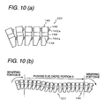
- A belt used in a belt type continuously variable transmission is constituted by holding a number of elements by a ring in an endless shape. For example, as shown by Fig.10 (a), an
element 140 comprises anear portion 142, aneck portion 143 and abody portion 144. Thick-walled portions 142a, 144a are formed at theear portion 142 and thebody portion 144, respectively. The vibration of belt is prevented by contacting the thick-walled portions 142a, 144a with theelement 140 disposed on a front side thereof (refer to, for example, JP-UM-B-5-37067). - However, in the
belt 107 with the above-described structure, the contact of theelement 140 with theelement 140 disposed on the front side thereof is restricted by the thick-walled portions 142a, 144a formed at theear portion 142 and thebody portion 144. Therefore, as shown by Fig. 10 (b), a rigidity of a pushing side chord portion N of thebelt 107 in a belt advancing direction cannot be sufficiently ensured and the vibration of belt is generated. Further, at a high belt peripheral speed, the pitching ofelement 140 is produced at an outlet of a drive pulley by advancing an outer side of theelement 140 faster. When the thick-walled portions 142a, 144a are formed at theear portion 142 and thebody portion 144, it is impossible to prevent the vibration of belt which is caused by the pitching ofelement 140 produced at the high belt peripheral speed. Further, also at a wrapping portion of thebelt 107, when theelement 140 is urged such that its V face becomes orthogonal to the pulley, in the case in which a plate thickness difference is produced within alocking edge portion 145 of thebody portion 144, thelocking edge portion 145 cannot stably be brought into contact with a rear face of theelement 140 on the front side and there is a possibility of accelerating wear of the V face. - Further, as shown in Fig. 8(a), since there is no contact point at the neck portion, the effective radius dT for bending moment can not be made to the sufficient value. Therefore, the pitching of the body portion is prevented mainly by bending moment of the neck portion with one portion in the center of the body portion and the locking edge portion as a center, and thus, it is difficult to prevent completely the pitching of the body portion.
- The invention has been carried out in view of such a problem and it is an object thereof to provide a belt for a continuously variable transmission sufficiently ensuring a rigidity at a pushing side chord portion in a belt advancing direction by restraining the pitching of a metal element.
- In order to resolve the above-described problem, a belt for a continuously variable transmission according to the invention (for example, a
metal V belt 7 according to an embodiment) comprises a metal ring in an endless shape (for example, aring 50 according to the embodiment), and a number of metal elements (for example,elements 40 according to the embodiment) held by the metal ring and aligned in a peripheral direction of the metal ring, wherein the metal element includes left and right locking edge portions including a V face brought into contact with a drive pulley and a driven pulley and being wrapped with the metal ring, a body portion disposed on an inner peripheral side of the metal ring, a head- portion disposed on an outer peripheral side of the metal ring and having an ear portion extended to left and right sides to be opposed to the locking edge portion, and a neck portion integrally connecting the body portion and the head portion, and wherein front faces of the ear portion, the neck portion and the locking edge portion of the metal element are formed with contact portions capable of bringing the contiguous metal elements into contact with each other. - In such a belt for a continuously variable transmission, it is preferable that plate thicknesses of the contact portion of the ear portion and the contact portion of the neck portion are formed by sizes substantially the same as each other, and a plate thickness of the contact portion of the locking edge portion is formed to be thinner than the plate thicknesses of the contact portions of the ear portion and the neck portion.
- Further, it is preferable that an upper end of the contact portion formed at the neck portion is disposed on an upper side of a lower end of the contact portion formed at the ear portion.
- When the belt for a continuously variable transmission according to the invention is constituted as described above, by the contact portions formed at the ear portion, the neck portion and the locking edge portion, a rigidity of the belt for a continuously variable transmission at a pushing side chord portion can sufficiently be endured. Further, even when the metal element is urged to be orthogonal to the pulley at the wrapping portion, by stably bringing the locking edge portions into contact with each other, uneven wear at the V face of the metal element can firmly be prevented.
- Further, the plate thicknesses of the contact portions of the ear portion and the neck portion are made by substantially the same size and the plate thickness of the contact portion of the locking edge portion is made to be thinner than the plate thicknesses of the contact portions of the ear portion and the neck portion. Thus, pitching of the metal element generated at an outlet of the drive pulley particularly at high belt peripheral speed can be prevented and vibration of the belt for a continuously variable transmission can be prevented.
- Further, the upper end of the contact portion formed at the neck portion is disposed on the upper side of the lower end of the contact portion formed at the ear portion. Thus, the metal element is prevented from being rotated in a pitching direction by constituting a pivot point by the contact portion of the ear portion. Further, by effectively preventing a bending stress of the neck portion by the rotation, the rigidity of the belt for a continuously variable transmission at the pushing side chord portion can be increased.
- Further, as shown in Fig. 8(b), there is the contact portion at one portion of the neck portion, and thus, the effective radius dl for the bendingmoment can be made to the sufficiently large value. Therefore, the pitching of the body portion can be prevented and the vibration of the element line of the pushing side chord portion can be prevented effectively.
-
- Fig.1 is a sectional view showing a total constitution of a belt type continuously variable transmission.
- Fig.2 is a skeleton view showing the total constitution of the belt type continuously variable transmission.
- Fig. 3 is a perspective view showing a structure of a metal V belt.
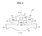
- Fig.4 is a rear view of an element constituting the metal V belt according to the invention.
- Fig.5 (a) illustrates a sectional view taken along a line V-V of Fig. 4 in a case of forming a stepped portion at a boundary of a neck portion and a saddle face on a rear face side.
- Fig.5 (b) illustrates a sectional view taken along a line V-V of Fig.4 in a case of forming a stepped portion at the boundary of the neck portion and the saddle face on a front face side.
- Fig.5(c) illustrates a sectional view taken along a line V-V of Fig. 4 in a case of forming the neck portion and a locking edge portion on the front face side such that plate thicknesses thereof are thinned in a taper shape.
- Fig.6 is a view showing a metal V belt mechanism.
- Fig.7 (a) illustrates a view enlarging an essential portion showing operation of the metal V belt according to the invention.
- Fig.7 (b) illustrates a view showing operation of the metal V belt according to the invention and showing states of a wrapping portion and a pushing side chord portion.
- Fig.8 (a) illustrates a plane view showing a structure of an element of a related art.
- Fig.8 (b) illustrates a plain view showing a structure of the element according to the invention.
- Fig.9 is a graph showing a rate of varying a tension of the metal V belt.
- Fig.10 (a) illustrates a view enlarging an essential portion showing operation of a metal V belt of the related art.
- Fig.10 (b) illustrates a view showing operation of a metal V belt of the related art and showing states of a wrapping portion and a pushing side chord portion.
- A preferable embodiment of the invention will be explained as follows in reference to the drawings. Fig.1 and Fig.2 show a total constitution of a belt type continuously variable transmission 1 using a belt for a continuously variable transmission (hereinafter, refer to as 'metal V belt 7') according to the embodiment. The belt type continuously variable transmission (CVT) 1 comprises a
transmission input shaft 2, atransmission counter shaft 3, a metalV belt mechanism 4, and a planetary gear type forward/rearward switching mechanism 20. Thetransmission input shaft 2 is connected to an output shaft of an engine ENG via aflywheel damper 10. Thetransmission counter shaft 3 is arranged in parallel with thetransmission input shaft 2. The metalV belt mechanism 4 is arranged between the twoshafts rearward switching mechanism 20 is arranged on thetransmission input shaft 2. The belt type continuously variable transmission 1 is provided with ahydraulic pump 30, a speedchange control valve 60 and the like. A working oil from thehydraulic pump 30 is fed to the speedchange control valve 60 via anoil path 30c. Then, the working oil is fed to the metalV belt mechanism 4 viaoil paths change control valve 60 to execute a speed change control. - The metal
V belt mechanism 4 comprises adrive pulley 5, a drivenpulley 8, and themetal V belt 7. Thedrive pulley 5 is rotatably arranged on thetransmission input shaft 2. The drivenpulley 8 is arranged on thetransmission counter shaft 3 to rotate integrally with thetransmission counter shaft 3. Themetal V belt 7 is wrapped to hang between the twopulleys - As shown by Fig.3, the
metal V belt 7 comprises a number of connectedelements 40 and two bundles ofrings 50 to which theelements 40 are attached to being aligned in a peripheral direction ofrings 50. As shown by Fig. 4 and Fig. 5, theelement 40 is formed in a flat plate shape and comprises ahead portion 41, aneck portion 43 and abody portion 44. Thehead portion 41 is extended withear portions 42 on the left and on the right. Thebody portion 44 is extended in a left and right direction. Theneck portion 43 connects thehead portion 41 and thebody portion 44 in an up and down direction. A front face (a face in an advancing direction of themetal V belt 7 pushed out from the drive pulley 5) of thehead portion 41 is projected to form with anose portion 47. A rear face of thehead portion 41 is formed with anose hole 48 in a recess shape. Therefore, theelements 40 are connected by fitting thenose portion 47 at thenose hole 48. Therings 50 are pinched byring slots 49 formed between theear portions 42 formed on the left and on the right of theelement 40 and an upper face (saddle face) of a lockingedge portion 45 constituting an upper portion of thebody portion 44. V faces 46 are formed on both left and right side faces of thebody portion 44, and the V faces 46 are brought into contact to be pinched by V faces 11 of the drive and thepulleys - The
drive pulley 5 comprises a fixedpulley half member 5A rotatably arranged on thetransmission input shaft 2 and a movablepulley half member 5B movable relative to the fixedpulley half member 5A in an axial direction. A driveside cylinder chamber 6 is formed on a side of the movablepulley half member 5B. By a hydraulic pressure supplied from the speedchange control valve 60 via theoil path 30d, a thrust in an axial direction (thrust in the axial direction of the drive pulley) for moving the movablepulley half member 5B in the axial direction is generated. A portion of the fixedpulley half member 5A brought into contact with themetal V belt 7 is formed with the V face 11, and the V face 11 is formed also at a face of the movablepulley half member 5B opposed to the fixedpulley half member 5A. Further, themetal V belt 7 is pinched by the V faces 11 formed at the fixedpulley half member 5A and the movablepulley half member 5B. - The driven
pulley 8 comprises a fixedpulley half member 8A and a movablepulley half member 8B movable relative to the fixedpulley half member 8A in an axial direction. A drivenside cylinder chamber 9 is formed at a side of the movablepulley half member 8B. By a hydraulic pressure supplied from the speedchange control valve 60 via theoil path 30e, a thrust in an axial direction (thrust in the axial direction of the driven pulley) for moving the movablepulley half member 8B in the axial direction is generated. The drivenpulley 8 is also formed with the V faces 11 similar to those of thedrive pulley 5 and themetal V belt 7 is pinched between the V faces 11 of the fixedpulley half member 8A and the movablepulley half member 8B. - In this way, by controlling the hydraulic pressure (pulley side pressure controlling hydraulic pressure) supplied to the drive
side cylinder chamber 6 and the drivenside cylinder chamber 9, a pulley shaft thrust which does not produce slip at the metal V belt 7 (referred to as slip preventing shaft thrust) can be set. Further, pulley widths of thedrive pulley 5 and the drivenpulley 8 can variably be set, and a gear ratio can be controlled steplessly (continuous) by continuously changing radii of wrapping themetal V belt 7 to the twopulleys - The planetary gear type forward/rearward switching
mechanism 20 is provided with a single pinion type planetary gear mechanism. The planetary gear type forward/rearward switchingmechanism 20 comprises asun gear 21 coupled to thetransmission input shaft 2, a carrier 22 coupled to the fixedpulley half member 5A, aring gear 23 capable of being fixedly held by a rearward movingbrake 25, and a forward moving clutch 24 capable of connecting thesun gear 21 and thering gear 23. When the forward moving clutch 24 is engaged, thesub gear 21, the carrier 22 and thering gear 23 are integrally rotated with thetransmission input shaft 2 and thedrive pulley 5 is driven to rotate in a direction the same as that of the transmission input shaft 2 (forward moving direction). On the other hand, when the rearward movingbrake 25 is engaged, thering gear 23 is fixedly held and the carrier 22 is driven to rotate in a direction reverse to that of the sun gear 21 (rearward moving direction). - Power from the engine ENG transmitted to the
transmission counter shaft 3 by changing speed thereof via the metalV belt mechanism 4, the planetary gear type forward/rearward switchingmechanism 20 constituted as described above is transmitted to adifferential mechanism 29 via astart clutch 26 andgears - Further, as described above, a speed change control is carried out by controlling to supply the hydraulic pressure to the drive side and the driven
side cylinder chambers change control valve 60. The speedchange control valve 60 is controlled to be operated by speed change control signals CDR, CDN from acontrol unit 70. The speedchange control valve 60 comprises two pieces of solenoid valves for controlling the hydraulic pressures supplied to the driveside cylinder chamber 6 and the drivenside cylinder chamber 9. The hydraulic pressures in the twocylinder chambers change control unit 70 and the solenoid valves, and thus, the thrusts in the axial direction of the drive and the driven pulleys operated to the drive and drivenpulleys rotational signal detector 71 and a driven pulley rotational signal NDN provided from a driven siderotational number detector 72 are detected and inputted to the speedchange control unit 70. - In the metal
V belt mechanism 4 of the belt type continuously variable transmission 1 constituted as describe above, theelements 40 constituting themetal V belt 7 are brought into contact with each other to transmit a torque from thedrive pulley 5 to the drivenpulley 8. Therefore, there is a concern of generating vibration at themetal V belt 7 by contact of theelements 40 or pitching, or generating uneven wear at the contact faces (V faces 46) between the drive and the drivenpulleys metal V belt 7 or twist at themetal V belt 7. Hence, as shown by Fig. 4 and Fig. 5, theelement 40 of the embodiment is constituted by making plate thicknesses of a front end portion of theear portion 42 and center portions of theneck portion 43 and the lockingedge portion 45 thicker than that of other portion to formcontact portions contact portions contiguous elements 40 are brought into contact with each other and thus, vibration or the like of themetal V belt 7 can be prevented. - Further, thicknesses of the
contact portions ear portion 42 and theneck portion 43 are formed to be substantially the same size. A thickness of thecontact portion 45a of the lockingedge portion 45 is formed to be thinner than the thicknesses of thecontact portions element 40, a boundary portion of theneck portion 43 and the saddle face may be formed in a step-like shape. Or, as shown by Fig. 5 (b), on the front face side of theelement 40, a boundary portion of theneck portion 43 and the saddle face may be formed in a step-like shape. Or as shown by Fig.5 (c) on the front face side of theelement 40, the plate thickness may be formed to be thinned in a taper shape from a lower portion of theneck portion 43 to the lockingedge portion 45. - Now, an explanation will be given of operation of the
metal V belt 7 constituted in this way in reference to Fig.7. Further, as shown by Fig.6, a portion of themetal V belt 7 wrapped to hang on thedrive pulley 5 is referred to as a wrapping portion M and a portion thereof pushed out from thedrive pulley 5 is referred to as a pushing side chord portion N. Further, in Fig.7, thecontact portions - First, as shown by Fig.7, since the
metal V belt 7 is bent along thedrive pulley 5, thecontact portion 45a of the lockingedge portion 45 is brought into contact with the rear face of theelement 40 disposed on a front side thereof (S3 in Fig.7 (a)).Therefore, even when theelements 40 are urged to be orthogonal to the drive pulley 5 (or the driven pulley 8), the lockingedge portions 45 of theelements 40 are brought into contact with each other to be stably supported thereby and vibration is not generated. Therefore, uneven wear of the V face 46 can firmly be prevented. - Further, when the
metal V belt 7 is pushed out from the wrapping portion M to the pushing side chord portion N, first, thecontact portion 43a of theneck portion 43 is brought into contact with the rear face of theelement 40 on the front side thereof (S1 in Fig.7 (a)), next, thecontact portion 42a of theear portion 42 is brought into contact with the rear face of theelement 40 on the front side to enter the pushing side chord portion N (S2 in Fig. 7 (a)). Therefore, when theelement 40 is pushed out from the wrapping portion M to the pushing side chord portion N, an impact when theelement 40 on the rear side is brought into contact with theelement 40 on the front side is dispersed to alleviate by two times of thecontact portions neck portion 43 and theear portion 42. Therefore, vibration of themetal V belt 7 by the impact by bringing theelements 40 into contact with each other is not induced. - Further, when a force of pushing out the
metal V belt 7 from thedrive pulley 5 is large, in the pushing side chord portion, also the thick-walled portion 45a of the lockingedge portion 45 is brought into contact with the rear face of theelement 40 on the front side and stability of themetal V belt 7 can be increased. - According to the embodiment, as shown by Fig. 4, in comparison with the
element 140 of the related art, thecontact portion 43a is formed at theneck portion 43 and therefore, a width of vibration of themetal V belt 7 can be reduced. For example, Fig. 9 is a graph showing a rate of varying a tension (when ratio: LOW, Nin: 3000rpm, Tin: 10Kgf·m) at the chord portion N of themetal V belt 7 having such anelement contact portions ear portion 42 and theneck portion 43 and a plate thickness of thecontact portion 45a of the lockingedge portion 45. As shown by Fig.9, when the upper and lower plate thickness difference is 3µm, the tension varying rate according to the embodiment (G2 in Fig. 9) can be made to be 1/3 of the tension varying rate of themetal V belt 107 when theelement 140 of the related art is used (G1 in Fig.9). - The reason of capable of restraining an amount of varying the tension at the chord portion N of the
metal V belt 7 to 1/3 of that of the related art is that as shown by Fig.7, at an outlet of the drive pulley 5 (a boundary of the wrapping portion M and the pushing side chord portion N), pitching of the element 4-0 which comes to the pushing side chord portion N to shift to a linear movement while falling forward to pitch can be restrained by bringing one portion of thecontact portion 43a of theneck portion 43 into contact with the rear face of theelement 40 prior to thecontact portion 42a of theear portion 42. Particularly, when themetal V belt 7 is at high belt peripheral speed, vibration caused by pitching by proceeding an outer side of theelement 40 faster at the output of thedrive pulley 5 can be prevented. - Further, as shown by Fig.4, in the case of the
element 40 according to the embodiment, an upper end of thecontact portion 43a of theneck portion 43 is formed to dispose on an upper side of a lower end of thecontact portion 42a of theear portion 42. Therefore, a gap between theneck portions 43 of theelements 40 contiguous each other is nullified and therefore, a rigidity of theneck portion 43 is further increased and a vibration preventing effect is increased. - Further, a center portion of the
body portion 44 and thecontact portion 43a of theneck portion 43 may be continuous, and all of the effects of the embodiment can be achieved. - The principle effects achieved by the embodiment of the invention explained above will be summarized as follows.
- First, the
elements 40 are brought into contact with each other at thecontact portions 42a at two left and right symmetrical portions formed at theear portion 42, thecontact portion 43a formed at theneck portion 43, and thecontact portion 45a formed at the center portion of the lockingedge portion 45 of thebody portion 44. Therefore, pitching centering on the lockingedge portion 45 at the pushing side chord portion N of themetal V belt 7 can effectively be prevented by thecontact portion 43a of theneck portion 43. Thus, the rigidity of themetal V belt 7 in a belt advancing direction at the pushing side chord portion N can sufficiently be endured. Further, also at the wrapping portion M, even when theelement 40 is urged to be orthogonal to thepulley edge portions 45 can stably be brought into contact with each other by thecontact portions 45a and therefore, uneven wear of the V face 46 of theelement 40 can firmly be prevented. - Second, with regard to portions formed with the
contact portions ear portion 42 and theneck portion 43 are made to be substantially the same and the plate thickness of the lockingedge portion 45 is made to be thinner than the plate thicknesses of theear portion 42 and theneck portion 43. Therefore, at the outlet of thedrive pulley 5, theelement 40 which comes out from the wrapping portion M to the pushing side chord portion N and is going to be shifted to the linear movement while falling forward to pitch is brought into contact with the rear face of theelement 40 on the front side by one portion of thecontact portion 43a formed at theneck portion 43 prior to thecontact portion 42a formed at theear portion 42. Thus, in addition to the first effect, the pitching ofelements 40 can be prevented and vibration caused by the pitching generated at the outlet of thedrive pulley 5 at high belt peripheral speed can be prevented. - Third, since the upper end of the
contact portion 43a formed at theneck portion 43 is disposed on the upper side of thelower end portion 42a formed at theear portion 42 and therefore, the rigidity at the pushing side chord portion N of themetal V belt 7 can be increased. - A belt (metal V belt) has a number of elements held by a ring in an endless shape and aligned in a peripheral direction of the ring. The element includes a head portion, a neck portion and a body portion. The body portion has a V face brought into contact with a drive pulley and a driven pulley and left and right locking edge portions wrapped with the ring and disposed on an inner peripheral side of the ring. The head portion is disposed on an outer peripheral side of the ring and having an ear portion extended to left and to right sides to be opposed to the locking edge portion. The neck portion integrally connects the body portion and the head portion. Front faces of the ear portion, the neck portion and the locking edge portion of the element are formed with contact portions capable of bringing the contiguous elements into contact with each other.
Claims (4)
- A belt for a continuously variable transmission comprising:a metal ring in an endless shape; anda number of metal elements held by the metal ring and aligned in a peripheral direction of the metal ring, each of the metal elements having left and right locking edge portions including a V face brought into contact with a drive pulley and a driven pulley and being wrapped with the metal ring, a body portion disposed on an inner peripheral side of the metal ring , a head portion disposed on an outer peripheral side of the metal ring and including an ear portion extended to left and right sides to be opposed to the locking edge portion, and a neck portion integrally connecting the body portion and the head portion,wherein front faces of the ear portion, the neck portion and the locking edge portion of the metal element are formed with contact portions capable of bringing the contiguous metal elements into contact with each other.
- The belt for a continuously variable transmission according to Claim 1, wherein plate thicknesses of the contact portion of the ear portion and the contact portion of the neck portion are formed by sizes substantially the same as each other, and a plate thickness of the contact portion of the locking edge portion is formed to be thinner than the plate thicknesses of the contact portions of ear portion and the neck portion.
- The belt for a continuously variable transmission according to Claim 1, wherein an upper end of the contact portion formed at the neck portion is disposed on an upper side of a lower end of the contact portion formed at the ear portion.
- The belt for a continuously variable transmission according to Claim 2, wherein an upper end of the contact portion formed at the neck portion is disposed on an upper side of a lower end of the contact portion formed at the ear portion.
Applications Claiming Priority (1)
| Application Number | Priority Date | Filing Date | Title |
|---|---|---|---|
| JP2004296530A JP4129448B2 (en) | 2004-10-08 | 2004-10-08 | Belt for continuously variable transmission |
Publications (2)
| Publication Number | Publication Date |
|---|---|
| EP1645777A1 true EP1645777A1 (en) | 2006-04-12 |
| EP1645777B1 EP1645777B1 (en) | 2007-11-28 |
Family
ID=35478734
Family Applications (1)
| Application Number | Title | Priority Date | Filing Date |
|---|---|---|---|
| EP05021959A Expired - Lifetime EP1645777B1 (en) | 2004-10-08 | 2005-10-07 | Belt for continuously variable transmission |
Country Status (5)
| Country | Link |
|---|---|
| US (1) | US7846049B2 (en) |
| EP (1) | EP1645777B1 (en) |
| JP (1) | JP4129448B2 (en) |
| CN (1) | CN100547260C (en) |
| DE (1) | DE602005003528T2 (en) |
Families Citing this family (16)
| Publication number | Priority date | Publication date | Assignee | Title |
|---|---|---|---|---|
| JP2008069893A (en) * | 2006-09-14 | 2008-03-27 | Honda Motor Co Ltd | Soundproof structure |
| JP5693465B2 (en) * | 2008-12-19 | 2015-04-01 | ローベルト ボツシユ ゲゼルシヤフト ミツト ベシユレンクテル ハフツングRobert Bosch Gmbh | Drive belt |
| US9080639B2 (en) * | 2011-05-27 | 2015-07-14 | Toyota Jidosha Kabushiki Kaisha | Driving belt and method for assembling the same |
| DE112012006666T5 (en) * | 2012-07-06 | 2015-03-19 | Honda Motor Co., Ltd. | Element for metallic belt |
| WO2014156432A1 (en) * | 2013-03-28 | 2014-10-02 | 本田技研工業株式会社 | Metal belt for continuously variable transmission |
| CN105264261B (en) * | 2013-06-04 | 2017-05-24 | 本田技研工业株式会社 | Metallic belt for stepless transmission |
| JP2015194226A (en) * | 2014-03-31 | 2015-11-05 | 本田技研工業株式会社 | Metal belt for continuously variable transmission |
| JP6160631B2 (en) * | 2015-01-13 | 2017-07-12 | トヨタ自動車株式会社 | Lubricating device for belt type continuously variable transmission |
| JP6506062B2 (en) * | 2015-03-24 | 2019-04-24 | 本田技研工業株式会社 | Method of manufacturing metal element for continuously variable transmission |
| JP6444355B2 (en) * | 2016-11-04 | 2018-12-26 | 本田技研工業株式会社 | Metal element for continuously variable transmission and method for manufacturing metal element for continuously variable transmission |
| US11149820B2 (en) * | 2017-03-03 | 2021-10-19 | Aisin Aw Co., Ltd. | Element designing method and power transfer belt |
| JP6523381B2 (en) | 2017-07-28 | 2019-05-29 | 本田技研工業株式会社 | Method of manufacturing metal element for continuously variable transmission |
| JP6621495B2 (en) * | 2018-04-03 | 2019-12-18 | 本田技研工業株式会社 | Metal element for continuously variable transmission and method for manufacturing metal element for continuously variable transmission |
| NL1043501B1 (en) * | 2019-12-10 | 2021-08-31 | Bosch Gmbh Robert | A transverse segment for a drive belt and a drive belt for a continuously variable transmission including the transverse segment and a ring stack |
| CN112555369A (en) * | 2020-12-02 | 2021-03-26 | 中建科工集团有限公司 | Transmission chain, driving module and continuously variable transmission |
| DE102021108897A1 (en) | 2021-04-09 | 2022-10-13 | Schaeffler Technologies AG & Co. KG | Continuously variable transmission with a vibration absorber |
Citations (2)
| Publication number | Priority date | Publication date | Assignee | Title |
|---|---|---|---|---|
| US4610648A (en) * | 1983-10-31 | 1986-09-09 | Dayco Corporation | Belt construction for a continuously variable transmission, transverse belt element therefor and methods of making the same |
| EP1267091A2 (en) * | 2001-06-12 | 2002-12-18 | Van Doorne's Transmissie B.V. | Transverse element having a conical neck portion |
Family Cites Families (13)
| Publication number | Priority date | Publication date | Assignee | Title |
|---|---|---|---|---|
| NL7900923A (en) * | 1979-02-06 | 1980-08-08 | Doornes Transmissie Bv | COMPOSITE DRIVE BELT PROVIDED WITH CROSS-ELEMENTS WITH COUPLERS, AND CROSS-ELEMENT FOR A BELT. |
| JPS5718836A (en) * | 1980-07-03 | 1982-01-30 | Nippon Denso Co Ltd | Transmission belt |
| US4595385A (en) * | 1984-03-26 | 1986-06-17 | Dayco Corporation | Belt construction, transverse belt element therefor and method of making the same |
| JPH0537067Y2 (en) | 1986-05-28 | 1993-09-20 | ||
| NL8900072A (en) * | 1989-01-12 | 1990-08-01 | Doornes Transmissie Bv | CROSS-ELEMENT FOR A BELT. |
| JPH0723643Y2 (en) * | 1989-11-16 | 1995-05-31 | 本田技研工業株式会社 | Metal V belt |
| JP3715126B2 (en) | 1998-04-10 | 2005-11-09 | 本田技研工業株式会社 | Belt for continuously variable transmission |
| ES2189083T3 (en) * | 1998-07-30 | 2003-07-01 | Doornes Transmissie Bv | TRANSMISSION BAND. |
| DE60005746T2 (en) * | 1999-06-18 | 2004-04-29 | Honda Giken Kogyo K.K. | Belt for continuously variable transmission |
| JP4229532B2 (en) * | 1999-07-05 | 2009-02-25 | 本田技研工業株式会社 | Belt for continuously variable transmission |
| JP3669680B2 (en) * | 2000-01-17 | 2005-07-13 | 本田技研工業株式会社 | Belt for continuously variable transmission |
| JP3983998B2 (en) | 2000-05-26 | 2007-09-26 | 本田技研工業株式会社 | Belt element for continuously variable transmission and punching method thereof |
| JP2002048194A (en) * | 2000-08-03 | 2002-02-15 | Honda Motor Co Ltd | Assembly method of belt for continuously variable transmission |
-
2004
- 2004-10-08 JP JP2004296530A patent/JP4129448B2/en not_active Expired - Lifetime
-
2005
- 2005-10-07 US US11/245,065 patent/US7846049B2/en active Active
- 2005-10-07 DE DE602005003528T patent/DE602005003528T2/en not_active Expired - Lifetime
- 2005-10-07 EP EP05021959A patent/EP1645777B1/en not_active Expired - Lifetime
- 2005-10-08 CN CNB200510108458XA patent/CN100547260C/en not_active Expired - Lifetime
Patent Citations (2)
| Publication number | Priority date | Publication date | Assignee | Title |
|---|---|---|---|---|
| US4610648A (en) * | 1983-10-31 | 1986-09-09 | Dayco Corporation | Belt construction for a continuously variable transmission, transverse belt element therefor and methods of making the same |
| EP1267091A2 (en) * | 2001-06-12 | 2002-12-18 | Van Doorne's Transmissie B.V. | Transverse element having a conical neck portion |
Also Published As
| Publication number | Publication date |
|---|---|
| DE602005003528T2 (en) | 2008-03-13 |
| JP2006105368A (en) | 2006-04-20 |
| US20060079366A1 (en) | 2006-04-13 |
| CN100547260C (en) | 2009-10-07 |
| CN1757952A (en) | 2006-04-12 |
| JP4129448B2 (en) | 2008-08-06 |
| EP1645777B1 (en) | 2007-11-28 |
| US7846049B2 (en) | 2010-12-07 |
| DE602005003528D1 (en) | 2008-01-10 |
Similar Documents
| Publication | Publication Date | Title |
|---|---|---|
| EP1645777B1 (en) | Belt for continuously variable transmission | |
| EP2397723A1 (en) | Continuously variable transmission mechanism and gearbox employing continuously variable transmission mechanism | |
| EP1553333B1 (en) | Continuously variable transmission | |
| CN104334917B (en) | Metal tape element | |
| US7163476B2 (en) | Belt type continuously variable transmission | |
| CN104334918B (en) | Components for metal strips | |
| JP4505316B2 (en) | Belt for continuously variable transmission | |
| JP2000074149A (en) | Belt for continuously variable transmission | |
| KR100460903B1 (en) | Continuously variable transmission for vehicles | |
| CN111550523B (en) | CVT | |
| CN112443632B (en) | Continuously variable transmission and endless drive belt | |
| KR100199170B1 (en) | Continuously variable transmission for vehicles | |
| KR100260168B1 (en) | Cvt for vehicle | |
| KR100254448B1 (en) | Continuously variable transmission for rear-wheel drive vehicle | |
| KR200199617Y1 (en) | Stepless speeding changer for a vehicle | |
| JPH0562260B2 (en) | ||
| KR19980017163A (en) | Stepless Transmission for Vehicles | |
| JP2018185034A (en) | Vehicle continuously variable transmission | |
| KR19980017164A (en) | Stepless Transmission for Vehicles | |
| KR19980041866U (en) | Stepless transmission for rear wheel drive vehicles | |
| KR19980017029A (en) | Stepless Transmission for Vehicles |
Legal Events
| Date | Code | Title | Description |
|---|---|---|---|
| PUAI | Public reference made under article 153(3) epc to a published international application that has entered the european phase |
Free format text: ORIGINAL CODE: 0009012 |
|
| AK | Designated contracting states |
Kind code of ref document: A1 Designated state(s): AT BE BG CH CY CZ DE DK EE ES FI FR GB GR HU IE IS IT LI LT LU LV MC NL PL PT RO SE SI SK TR |
|
| AX | Request for extension of the european patent |
Extension state: AL BA HR MK YU |
|
| 17P | Request for examination filed |
Effective date: 20060811 |
|
| 17Q | First examination report despatched |
Effective date: 20060915 |
|
| AKX | Designation fees paid |
Designated state(s): DE GB NL |
|
| GRAP | Despatch of communication of intention to grant a patent |
Free format text: ORIGINAL CODE: EPIDOSNIGR1 |
|
| GRAS | Grant fee paid |
Free format text: ORIGINAL CODE: EPIDOSNIGR3 |
|
| GRAA | (expected) grant |
Free format text: ORIGINAL CODE: 0009210 |
|
| AK | Designated contracting states |
Kind code of ref document: B1 Designated state(s): DE GB NL |
|
| REG | Reference to a national code |
Ref country code: GB Ref legal event code: FG4D |
|
| REF | Corresponds to: |
Ref document number: 602005003528 Country of ref document: DE Date of ref document: 20080110 Kind code of ref document: P |
|
| PLBE | No opposition filed within time limit |
Free format text: ORIGINAL CODE: 0009261 |
|
| STAA | Information on the status of an ep patent application or granted ep patent |
Free format text: STATUS: NO OPPOSITION FILED WITHIN TIME LIMIT |
|
| 26N | No opposition filed |
Effective date: 20080829 |
|
| PGFP | Annual fee paid to national office [announced via postgrant information from national office to epo] |
Ref country code: GB Payment date: 20101006 Year of fee payment: 6 |
|
| GBPC | Gb: european patent ceased through non-payment of renewal fee |
Effective date: 20111007 |
|
| PG25 | Lapsed in a contracting state [announced via postgrant information from national office to epo] |
Ref country code: GB Free format text: LAPSE BECAUSE OF NON-PAYMENT OF DUE FEES Effective date: 20111007 |
|
| PGFP | Annual fee paid to national office [announced via postgrant information from national office to epo] |
Ref country code: NL Payment date: 20121010 Year of fee payment: 8 |
|
| REG | Reference to a national code |
Ref country code: NL Ref legal event code: V1 Effective date: 20140501 |
|
| REG | Reference to a national code |
Ref country code: DE Ref legal event code: R084 Ref document number: 602005003528 Country of ref document: DE |
|
| PG25 | Lapsed in a contracting state [announced via postgrant information from national office to epo] |
Ref country code: NL Free format text: LAPSE BECAUSE OF NON-PAYMENT OF DUE FEES Effective date: 20140501 |
|
| REG | Reference to a national code |
Ref country code: DE Ref legal event code: R084 Ref document number: 602005003528 Country of ref document: DE Effective date: 20140821 |
|
| PGFP | Annual fee paid to national office [announced via postgrant information from national office to epo] |
Ref country code: DE Payment date: 20150929 Year of fee payment: 11 |
|
| REG | Reference to a national code |
Ref country code: DE Ref legal event code: R119 Ref document number: 602005003528 Country of ref document: DE |
|
| PG25 | Lapsed in a contracting state [announced via postgrant information from national office to epo] |
Ref country code: DE Free format text: LAPSE BECAUSE OF NON-PAYMENT OF DUE FEES Effective date: 20170503 |