EP1645771A2 - Thin film sensor for brake lining pad wear and brake temperature sensing - Google Patents
Thin film sensor for brake lining pad wear and brake temperature sensing Download PDFInfo
- Publication number
- EP1645771A2 EP1645771A2 EP05020819A EP05020819A EP1645771A2 EP 1645771 A2 EP1645771 A2 EP 1645771A2 EP 05020819 A EP05020819 A EP 05020819A EP 05020819 A EP05020819 A EP 05020819A EP 1645771 A2 EP1645771 A2 EP 1645771A2
- Authority
- EP
- European Patent Office
- Prior art keywords
- sensor
- brake
- thin film
- wear
- resistance
- Prior art date
- Legal status (The legal status is an assumption and is not a legal conclusion. Google has not performed a legal analysis and makes no representation as to the accuracy of the status listed.)
- Withdrawn
Links
- 239000010409 thin film Substances 0.000 title claims description 25
- 238000005259 measurement Methods 0.000 claims abstract description 24
- 239000000758 substrate Substances 0.000 claims description 8
- 230000000750 progressive effect Effects 0.000 claims description 4
- 238000009529 body temperature measurement Methods 0.000 claims description 3
- 239000004020 conductor Substances 0.000 claims description 2
- 229920001169 thermoplastic Polymers 0.000 claims description 2
- 239000004416 thermosoftening plastic Substances 0.000 claims description 2
- 239000008393 encapsulating agent Substances 0.000 claims 2
- 230000001747 exhibiting effect Effects 0.000 claims 1
- 239000010408 film Substances 0.000 description 4
- 239000000463 material Substances 0.000 description 4
- RYGMFSIKBFXOCR-UHFFFAOYSA-N Copper Chemical compound [Cu] RYGMFSIKBFXOCR-UHFFFAOYSA-N 0.000 description 3
- 239000010949 copper Substances 0.000 description 3
- 229910052802 copper Inorganic materials 0.000 description 3
- 238000005538 encapsulation Methods 0.000 description 3
- 239000002184 metal Substances 0.000 description 3
- 229910052751 metal Inorganic materials 0.000 description 3
- 230000006378 damage Effects 0.000 description 2
- 238000001514 detection method Methods 0.000 description 2
- 238000000465 moulding Methods 0.000 description 2
- 238000013021 overheating Methods 0.000 description 2
- 230000002730 additional effect Effects 0.000 description 1
- 230000000712 assembly Effects 0.000 description 1
- 238000000429 assembly Methods 0.000 description 1
- 238000012790 confirmation Methods 0.000 description 1
- 230000002596 correlated effect Effects 0.000 description 1
- 230000007423 decrease Effects 0.000 description 1
- 238000013461 design Methods 0.000 description 1
- 239000003779 heat-resistant material Substances 0.000 description 1
- 238000007689 inspection Methods 0.000 description 1
- 150000002739 metals Chemical class 0.000 description 1
- 238000012986 modification Methods 0.000 description 1
- 230000004048 modification Effects 0.000 description 1
- 238000012544 monitoring process Methods 0.000 description 1
- 238000012360 testing method Methods 0.000 description 1
- 229920005992 thermoplastic resin Polymers 0.000 description 1
- 230000001052 transient effect Effects 0.000 description 1
- 230000000007 visual effect Effects 0.000 description 1
Images

Classifications
-
- F—MECHANICAL ENGINEERING; LIGHTING; HEATING; WEAPONS; BLASTING
- F16—ENGINEERING ELEMENTS AND UNITS; GENERAL MEASURES FOR PRODUCING AND MAINTAINING EFFECTIVE FUNCTIONING OF MACHINES OR INSTALLATIONS; THERMAL INSULATION IN GENERAL
- F16D—COUPLINGS FOR TRANSMITTING ROTATION; CLUTCHES; BRAKES
- F16D66/00—Arrangements for monitoring working conditions, e.g. wear, temperature
- F16D66/02—Apparatus for indicating wear
- F16D66/021—Apparatus for indicating wear using electrical detection or indication means
- F16D66/026—Apparatus for indicating wear using electrical detection or indication means indicating different degrees of lining wear
-
- F—MECHANICAL ENGINEERING; LIGHTING; HEATING; WEAPONS; BLASTING
- F16—ENGINEERING ELEMENTS AND UNITS; GENERAL MEASURES FOR PRODUCING AND MAINTAINING EFFECTIVE FUNCTIONING OF MACHINES OR INSTALLATIONS; THERMAL INSULATION IN GENERAL
- F16D—COUPLINGS FOR TRANSMITTING ROTATION; CLUTCHES; BRAKES
- F16D66/00—Arrangements for monitoring working conditions, e.g. wear, temperature
- F16D2066/001—Temperature
Definitions
- the invention relates to brake lining wear sensing and brake lining transient temperature detection and more particularly to a modular electrical resistance sensor which may be used to implement wear and temperature sensing.
- Effective brakes are essential to safe motor vehicle operation.
- Contemporary brake systems dissipate vehicle kinetic energy through brake friction pads as heat. These brake pads have a relatively short service life and require regular replacement.
- Heavy vehicles have historically exhibited problems with brake overheating, especially when the vehicles are descending along long grades. Overheating reduces stopping ability and accelerates brake pad wear.
- One such system for detecting wear provides a modular, progressive brake lining wear sensor.
- the sensor has a triangular, wedged shaped electrically resistive member disposed between a pair of conductive plates to define a triangular shaped sensor.
- the sensor is encapsulated within an erodable molding and connected to a sensing circuit by a pair of leads including a ground lead and a resistive lead. The ground lead and resistance lead emerge from the encapsulated sensor for connection to the sensing circuit.
- the sensor is disposed within the brake lining and is connected to the brake shoe. As the brake lining progressively wears, the triangular wedged shaped resistive member is also progressively worn away thus continuously changing the overall resistance of the sensor. The change in resistance provides for continuous indication of the state of wear of the brake lining.
- Another sensor design provides both wear and temperature sensing.
- a plurality of parallel connected resistors are connected to a sensing circuit.
- a thermistor provides temperature sensing.
- the resistors and the separate thermistor are mounted, spaced from one another, on a printed circuit board and the entire unit encapsulated within a single molding.
- the thermistor is connected to a grounded lead as are each of the resistors.
- a ground lead, a resistance lead and a thermistor lead emerge from the encapsulated module for connection to the sensing circuit.
- the module is disposed between linings in a drum brake so that the module is worn away with the linings.
- resistors or at least the conductive loops in which individual resistors are connected
- Three resistors are used to indicate 4 discrete levels of brake lining wear.
- a brake lining temperature and wear measurement system in which a modular electrical resistance sensor is positioned in gaps between brake linings for a drum brake.
- the modular electrical resistance sensor comprises a thin film of copper or some other electrically conductive material disposed on a wearable substrate. Substrate and film are encapsulated in a thermally stable, wearable thermoplastic.
- the modular sensor is positioned with the brake linings to wear down with the lining. This results in steadily increasing electrical resistance of the modular sensor correlated with wear of the lining.
- a measurement circuit associated with the modular sensor is programmed to equate electrical resistance to the degree of wear and operates when the sensor has assumed a steady state temperature at or near ambient temperature. During periods when the brakes are in use, resistance and the degree of wear last calculated become arguments into a function for determining brake lining temperature.
- a brake drum 13 has an inner brake surface 14 for frictionally engaging the brake lining 11.
- An actuator such as an S-cam arrangement displaces the brake shoes 15 outwardly towards the inner brake surface 14 bringing brake lining 11 into contact with the inner brake surface of the drum 13.
- Brake linings 11 are mounted to the brake shoe 15 to frictionally engage the brake drum 13 and thus provide braking force.
- the generic brake drum arrangement 10 and actuation mechanism is completely conventional and is well known in the art.
- Modular sensor 20 is preferably mounted between a pair of brake lining surfaces 11 in a gap 18 with a distal end substantially flush with the outer or friction surface of the brake lining 11.
- the specific connection of modular sensor 20 to brake shoe 15 is not shown.
- the specific manner of connection is not critical to the present invention. Any suitable connection that maintains radial alignment of the modular sensor 20 during braking may be employed.
- Fig. 2 is a perspective view of the preferred embodiment of the present invention prior to any significant wear.
- Modular sensor 20 is positioned on brake shoe 15 between the brake lining portions 11.
- a clip 22, having one end partially embedded in the sensor encapsulation, may be used to secure modular sensor 20 to brake shoe 15.
- Resistance lead 26 and ground lead 24 extend from the encapsulation material of sensor module 20.
- Fig. 3 is a perspective view of the modular sensor 20 of Fig. 2 in a partially worn state.
- Modular sensor 20 including its encapsulating material, the sensor material and sensor backing are all made of erodable material resulting in the sensor wearing to conform substantially to the profile of the brake lining 11 at all times.
- the resistance of the sensor increases as explained below. Resistance measurements may be equated with either brake lining 11 temperature and brake lining wear, although the measurements cannot be simultaneously equated to both variables. A determination of wear must precede brake lining temperature estimation as explained below.
- the progressive increase in resistance indicates the progression of brake lining wear, as determined under conditions of a steady state, and known, brake lining temperature.
- Resistance lead 26 may be seen connected to a measurement circuit 28, which may be implemented in a number of different ways.
- Measurement circuit 26 may incorporate an analog to digital converter, a data sending unit, cabling, and a programmable microcomputer attached to receive data over the cabling (not shown).
- a motor vehicle ambient temperature sensor 29 may be advantageously employed if present to provide ambient temperature readings to the measurement circuit 28. Such elements are believed well within those skilled in the art.
- Sensor 31 comprises a backing such as a circuit board 30 from one of the major surfaces of which has been etched a copper or metal coated pad 32.
- Metal coated pad 32 includes rails 34 and 38 and a thin film sheet 36 located between the rails and connected to the rails along two opposed edges.
- Thin film sheet 36 should be sufficiently thin relative to the rails 34, 38 to exhibit substantially greater resistivity than the rails.
- Electrical connection to rails 34 and 38 may be made by connection to pads 42 and 44, which are shown on a side of circuit board 30 bordering the etched major face. Alternatively, the leads may be taken off from pads left on the front, etched major face. Both front and back major faces of circuit board 30 are coated with a heat resistant, erodable thermoplastic resin, or similar electrically insulative, heat resistant material.
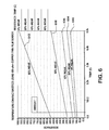
- FIG. 6 graphs of resistance of the metallic thin film 36 against temperature, at various stages of wear (from the top of the sensor module 20 in the direction A), are shown.
- the graph illustrates curves 602, 604, 606, 608 and 610 for a sensor which is: wholly intact (0% wear); one fifth eroded (20% wear); two fifths eroded (40% wear); three fifths eroded (60% wear); and four fifths eroded (80 % wear).
- each resistance curve, for a constant degree of wear is linear.
- resistance increases exponentially with destruction of the thin film 32 at any temperature and will be understood to increase without bound as the film is destroyed.
- the operator may choose at any given time to determine one of either the degree of destruction of the film or the temperature of the brakes. Determining brake temperature requires that brake pad wear is already determined. If the operator knows the temperature of the brake linings, wear of the linings can be estimated. If the degree of wear of the linings is known, then temperature of the linings may be estimated. Where a vehicle has stood for a period exceeding a minimum period of time, and the brakes have not been used, it may be assumed that the brakes take on the ambient temperature.
- This temperature may be measured by an sensor 29 on board the vehicle, such as an engine air intake temperature sensor, or the wear calculation can assume a value, e.g. 25 degrees Celsius, or the ambient temperature may be entered by the vehicle operator.
- the measurement circuit 28 can determine which wear curve the point of intersection between resistance and temperature on the graph falls closest to. The selected curve is then be saved as the current wear value.
- resistance in the film continues to be measured, but the result is mapped to the curve serving as the current estimate of wear to recover brake lining temperature.
- This may be implemented as a look up table.
- the curves 602, 604, 606, 608 and 610 are predetermined and may be stored as values in a look up table on a programmable computer.
- step 702 is executed to read the ambient temperature and the length of time that the vehicle has stood. Vehicle start may be any event marking a the end of a period where the vehicle has stood still, with the engine either idling or shut off.
- Step 704 marks determination as to whether the brake temperature is likely to be at a steady state near the ambient temperature. If the result of the test is in the affirmative, step 706 is executed to measure resistance of the brake lining resistance modules. Once the resistance has been determined step 708 is executed to determine wear of the sensor as a function of temperature and resistance.
- Step 710 represents selection of a curve (store wear). Wear of course may exceed a limit in which case a brake lining wear warning may be issued (step 711).
- step 712 Confirmation of vehicle start may be taken as an instance of operational application of the brakes. As long as the brakes are not applied the program may continue to loop back to step 702 for a wear measurement. Once the brakes are applied the YES branch is followed from step 712 to step 714, representing another measurement of the resistance of the brake lining resistance sensors. Since the brakes have been used they cannot be assumed to be at ambient temperature any longer, and the measurements are instead used as an argument into the wear curve selected at step 710. Temperature is returned at step 716 and may be displayed to the driver at step 718. The returned temperature is compared to a critical limit temperature at step 720. If the temperature does not exceed limit(s) the program loops back to step 712. If the brake lining temperature exceeds the critical temperature, step 722 is executed to issue a warning and the program loops back to step 712.
- the invention provides a low cost mechanism utilizing a single sensor type located in the area of the brakes.
- the sensor realizes both wear and temperature monitoring for brake linings by utilizing on board computing capacity to monitor the context of the measurements.
Landscapes
- Engineering & Computer Science (AREA)
- General Engineering & Computer Science (AREA)
- Mechanical Engineering (AREA)
- Braking Arrangements (AREA)
Abstract
Description
- The invention relates to brake lining wear sensing and brake lining transient temperature detection and more particularly to a modular electrical resistance sensor which may be used to implement wear and temperature sensing.
- Effective brakes are essential to safe motor vehicle operation. Contemporary brake systems dissipate vehicle kinetic energy through brake friction pads as heat. These brake pads have a relatively short service life and require regular replacement. Heavy vehicles have historically exhibited problems with brake overheating, especially when the vehicles are descending along long grades. Overheating reduces stopping ability and accelerates brake pad wear.
- Inspection of the brake system has traditionally involved disassembly of the wheel mechanism and visual examination of the pads. It has been recognized that it would be desirable to incorporate some kind of sensor into the brake pads that monitor wear of the pads without the need to disassemble the brake system. Were the same sensor used to monitor brake temperature the addition to vehicle complexity would be minimized.
- Various brake lining wear detection systems and brake temperature measurement systems are known in the art. One such system for detecting wear provides a modular, progressive brake lining wear sensor. The sensor has a triangular, wedged shaped electrically resistive member disposed between a pair of conductive plates to define a triangular shaped sensor. The sensor is encapsulated within an erodable molding and connected to a sensing circuit by a pair of leads including a ground lead and a resistive lead. The ground lead and resistance lead emerge from the encapsulated sensor for connection to the sensing circuit. The sensor is disposed within the brake lining and is connected to the brake shoe. As the brake lining progressively wears, the triangular wedged shaped resistive member is also progressively worn away thus continuously changing the overall resistance of the sensor. The change in resistance provides for continuous indication of the state of wear of the brake lining.
- Another sensor design provides both wear and temperature sensing. Here a plurality of parallel connected resistors are connected to a sensing circuit. A thermistor provides temperature sensing. The resistors and the separate thermistor are mounted, spaced from one another, on a printed circuit board and the entire unit encapsulated within a single molding. The thermistor is connected to a grounded lead as are each of the resistors. A ground lead, a resistance lead and a thermistor lead emerge from the encapsulated module for connection to the sensing circuit. The module is disposed between linings in a drum brake so that the module is worn away with the linings. With progressive wear the resistors (or at least the conductive loops in which individual resistors are connected) are progressively and sequentially worn away, increasing the resistance of the sensor in a series of discrete steps. Three resistors are used to indicate 4 discrete levels of brake lining wear.
- According to the invention there is provided a brake lining temperature and wear measurement system in which a modular electrical resistance sensor is positioned in gaps between brake linings for a drum brake. The modular electrical resistance sensor comprises a thin film of copper or some other electrically conductive material disposed on a wearable substrate. Substrate and film are encapsulated in a thermally stable, wearable thermoplastic. The modular sensor is positioned with the brake linings to wear down with the lining. This results in steadily increasing electrical resistance of the modular sensor correlated with wear of the lining. A measurement circuit associated with the modular sensor is programmed to equate electrical resistance to the degree of wear and operates when the sensor has assumed a steady state temperature at or near ambient temperature. During periods when the brakes are in use, resistance and the degree of wear last calculated become arguments into a function for determining brake lining temperature.
- Additional effects, features and advantages will be apparent in the written description that follows.
- The novel features believed characteristic of the invention are set forth in the appended claims. The invention itself however, as well as a preferred mode of use, further objects and advantages thereof, will best be understood by reference to the following detailed description of an illustrative embodiment when read in conjunction with the accompanying drawings, wherein:
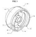
- Fig. 1 is a perspective view of a drum brake assembly incorporating the brake wear and temperature sensor of the present invention.
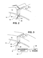
- Fig. 2 is a perspective view of a sensor module in accord with the present invention attached to a brake assembly.
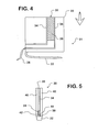
- Fig. 3 is a perspective view of a partially worn sensor module from Fig. 2.
- Fig. 4 is a front view of a sensor mounted on a circuit board.
- Fig. 5 is a side cross sectional view of the sensor module.
- Fig. 6 is a graph illustrating resistance of the sensor against temperature at various degrees of wear of the sensor.
- Fig. 7 is a flow chart of a program executed by the measurement circuit for estimating wear and temperature of the brake linings.
- The present invention is preferably employed in a
drum brake assembly 10 as shown in FIG. 1. However, themodular sensor 20 may be adopted for employment in other types of brake assemblies. Referring now to FIG. 1, abrake drum 13 has aninner brake surface 14 for frictionally engaging thebrake lining 11. An actuator such as an S-cam arrangement displaces thebrake shoes 15 outwardly towards theinner brake surface 14 bringingbrake lining 11 into contact with the inner brake surface of thedrum 13.Brake linings 11 are mounted to thebrake shoe 15 to frictionally engage thebrake drum 13 and thus provide braking force. The genericbrake drum arrangement 10 and actuation mechanism is completely conventional and is well known in the art. -
Modular sensor 20 is preferably mounted between a pair ofbrake lining surfaces 11 in agap 18 with a distal end substantially flush with the outer or friction surface of thebrake lining 11. The specific connection ofmodular sensor 20 tobrake shoe 15 is not shown. The specific manner of connection is not critical to the present invention. Any suitable connection that maintains radial alignment of themodular sensor 20 during braking may be employed. - Fig. 2 is a perspective view of the preferred embodiment of the present invention prior to any significant wear.
Modular sensor 20 is positioned onbrake shoe 15 between thebrake lining portions 11. Aclip 22, having one end partially embedded in the sensor encapsulation, may be used to securemodular sensor 20 tobrake shoe 15. Resistance lead 26 andground lead 24 extend from the encapsulation material ofsensor module 20. - Fig. 3 is a perspective view of the
modular sensor 20 of Fig. 2 in a partially worn state.Modular sensor 20, including its encapsulating material, the sensor material and sensor backing are all made of erodable material resulting in the sensor wearing to conform substantially to the profile of thebrake lining 11 at all times. As more ofmodular sensor 20 is worn, the resistance of the sensor increases as explained below. Resistance measurements may be equated with eitherbrake lining 11 temperature and brake lining wear, although the measurements cannot be simultaneously equated to both variables. A determination of wear must precede brake lining temperature estimation as explained below. Generally speaking, the progressive increase in resistance indicates the progression of brake lining wear, as determined under conditions of a steady state, and known, brake lining temperature.Resistance lead 26 may be seen connected to ameasurement circuit 28, which may be implemented in a number of different ways.Measurement circuit 26 may incorporate an analog to digital converter, a data sending unit, cabling, and a programmable microcomputer attached to receive data over the cabling (not shown). A motor vehicleambient temperature sensor 29 may be advantageously employed if present to provide ambient temperature readings to themeasurement circuit 28. Such elements are believed well within those skilled in the art. - Referring to Figs. 4 and 5 a
sensor 31 suitable for encapsulation to formsensor module 20 is illustrated.Sensor 31 comprises a backing such as acircuit board 30 from one of the major surfaces of which has been etched a copper or metal coatedpad 32. Metal coatedpad 32 includesrails thin film sheet 36 located between the rails and connected to the rails along two opposed edges.Thin film sheet 36 should be sufficiently thin relative to therails circuit board 30 is worn down from the top in the direction indicated by the arrow "A", andthin film sheet 36 is worn down along a free edge of the sheet betweenrails thin film sheet 36 decreases. A consequent increase in the resistance ofsheet 36 betweenrails rails pads circuit board 30 bordering the etched major face. Alternatively, the leads may be taken off from pads left on the front, etched major face. Both front and back major faces ofcircuit board 30 are coated with a heat resistant, erodable thermoplastic resin, or similar electrically insulative, heat resistant material. - Referring to Fig. 6, graphs of resistance of the metallic
thin film 36 against temperature, at various stages of wear (from the top of thesensor module 20 in the direction A), are shown. As is well known, the resistance of copper and most other metals increases linearly with temperature at temperatures typically encountered in motor vehicle operations. The graph illustratescurves thin film 32 at any temperature and will be understood to increase without bound as the film is destroyed. The operator may choose at any given time to determine one of either the degree of destruction of the film or the temperature of the brakes. Determining brake temperature requires that brake pad wear is already determined. If the operator knows the temperature of the brake linings, wear of the linings can be estimated. If the degree of wear of the linings is known, then temperature of the linings may be estimated. Where a vehicle has stood for a period exceeding a minimum period of time, and the brakes have not been used, it may be assumed that the brakes take on the ambient temperature. This temperature may be measured by ansensor 29 on board the vehicle, such as an engine air intake temperature sensor, or the wear calculation can assume a value, e.g. 25 degrees Celsius, or the ambient temperature may be entered by the vehicle operator. Upon measuring the resistance of thesensor module 20 themeasurement circuit 28 can determine which wear curve the point of intersection between resistance and temperature on the graph falls closest to. The selected curve is then be saved as the current wear value. When the vehicle is started and a driver begins to use the brakes, resistance in the film continues to be measured, but the result is mapped to the curve serving as the current estimate of wear to recover brake lining temperature. This may be implemented as a look up table. Thus thecurves - Referring to Fig. 7 implementation of the invention is linked to vehicle operation to determine likely periods when the brakes have assumed a steady state temperature close to the ambient temperature. Upon
vehicle start step 702 is executed to read the ambient temperature and the length of time that the vehicle has stood. Vehicle start may be any event marking a the end of a period where the vehicle has stood still, with the engine either idling or shut off. Step 704 marks determination as to whether the brake temperature is likely to be at a steady state near the ambient temperature. If the result of the test is in the affirmative,step 706 is executed to measure resistance of the brake lining resistance modules. Once the resistance has been determinedstep 708 is executed to determine wear of the sensor as a function of temperature and resistance. As noted above, these results may be precalculated and stored as a look up table graphically illustrated in Fig. 6. Step 710 represents selection of a curve (store wear). Wear of course may exceed a limit in which case a brake lining wear warning may be issued (step 711). - Once a new wear level has been determined, or following the NO branch from
decision step 704, vehicle start is confirmed atstep 712. Confirmation of vehicle start may be taken as an instance of operational application of the brakes. As long as the brakes are not applied the program may continue to loop back to step 702 for a wear measurement. Once the brakes are applied the YES branch is followed fromstep 712 to step 714, representing another measurement of the resistance of the brake lining resistance sensors. Since the brakes have been used they cannot be assumed to be at ambient temperature any longer, and the measurements are instead used as an argument into the wear curve selected atstep 710. Temperature is returned atstep 716 and may be displayed to the driver atstep 718. The returned temperature is compared to a critical limit temperature atstep 720. If the temperature does not exceed limit(s) the program loops back tostep 712. If the brake lining temperature exceeds the critical temperature,step 722 is executed to issue a warning and the program loops back tostep 712. - The invention provides a low cost mechanism utilizing a single sensor type located in the area of the brakes. The sensor realizes both wear and temperature monitoring for brake linings by utilizing on board computing capacity to monitor the context of the measurements.
- While the invention is shown in only one of its forms, it is not thus limited but is susceptible to various changes and modifications without departing from the spirit and scope of the invention.
Claims (10)
- A sensor for measuring operating temperature and for use in indicating progressive brake wear of a brake lining, the sensor comprising:an erodable substrate having a major surface and an upper edge bordering the major surface with the erodable substrate oriented to bring its upper edge into contact with a brake surface;a thin film of conductive material disposed on the major surface of the substrate and extending downwardly along the major surface from the upper edge;a pair of conductive rails defining first and second edges of the thin film which are generally perpendicular to the upper edge; andan encapsulant disposed over the major surface including the thin film and the conductive rails.
- The sensor according to claim 1, wherein the encapsulant enclosed the sensor to form a modular sensor unit.
- The sensor according to claim 2, wherein the pair of conductive leads have substantially lower resistance than does the thin film.
- The sensor according to claim 3, further comprising:a measurement circuit connected to at least one of the pair of conductive leads for reading resistance of the thin film, the measurement circuit providing means for indicating whether the thin film is at or near ambient temperature, means responsive to an indication that the thin film is at or near ambient temperature for determining degree of wear of a brake lining as a function of resistance, and means responsive to determination of a degree of wear of the brake lining and resistance of the thin film for determining temperature of the sensor.
- A brake system for a motor vehicle comprising:a brake drum having an inner surface;brake linings for wearing against the inner surface for braking a motor vehicle;a brake actuator for urging the brake linings into contact against the inner surface;an electrical resistance sensor mounted on the brake actuator in gaps between the brake linings to exhibit a wear profile conforming to that of the brake linings;the electrical resistance sensor exhibiting increasing resistance as it is worn down and with increasing temperature; anda measurement circuit connected to the electrical resistance sensor, the measurement circuit providing means for indicating whether the electrical resistance sensor is at or near ambient temperature, means responsive to an indication that the electrical resistance sensor is at or near ambient temperature for determining degree of wear of a brake lining as a function of resistance, and means responsive to determination of a degree of wear of the brake lining and resistance of the electrical resistance sensor for determining temperature of the sensor.
- A brake system according to claim 5, wherein the electrical resistance sensor further comprises:a wearable substrate having a major surface perpendicular to a wearing surface of the brake linings and a erodable edge;a thin film conductive member disposed over a portion off the major surface of the wearable substrate;a pair of conductive rails disposed on the first major surface defining first and second sides of the thin film conductive member, the thin film conductive member and the conductive rails being oriented so that the thin film conductive member is eroded along an edge running between the conductive rails.
- A brake system according to claim 6, wherein the substrate, the conductive rails and the thin film are encapsulated in a heat stable thermoplastic to form a sensor module.
- A brake system according to claim 7, further comprising a vehicle ambient temperature sensor coupled to the measurement circuit.
- A brake lining wear and temperature measurement system comprising:an electrically resistive element disposed in proximity to the brake lining, the electrically resistive element comprising an erodable sensor module fitted between brake lining pads with a resistive lead and a ground lead extending from the erodable sensor module;the electrically resistive element including a major surface and a thin film pad disposed on the major surface oriented to be gradually worn away along an edge thereof in conformance to a wear profile for the brake linings;first and second electrically conductive rails in contact with the thin film pad and defining first and second sides of the thin film pad, respectively; anda measurement circuit connected to the resistive lead for measuring the resistance of the thin film pad.
- A brake lining wear and temperature measurement system according to claim 9, further comprising:the measurement circuit including a program providing means for determining if brakes for a vehicle are likely to be at ambient temperature and, responsive to an affirmative determination that the brakes are likely to be at ambient temperature, providing means responsive to a measurement of the resistance for equating the measured resistance to a degree of wear of the sensor; andthe program stored on the measurement circuit further providing means responsive to determination that the brakes are likely to be at a temperature elevated compared to the ambient, using the measured resistance and the most recently obtained measurement of wear to determine brake lining temperature.
Applications Claiming Priority (1)
| Application Number | Priority Date | Filing Date | Title |
|---|---|---|---|
| US10/963,398 US7165657B2 (en) | 2004-10-11 | 2004-10-11 | Thin film sensor for brake lining pad wear and brake temperature sensing |
Publications (2)
| Publication Number | Publication Date |
|---|---|
| EP1645771A2 true EP1645771A2 (en) | 2006-04-12 |
| EP1645771A3 EP1645771A3 (en) | 2006-04-26 |
Family
ID=35744696
Family Applications (1)
| Application Number | Title | Priority Date | Filing Date |
|---|---|---|---|
| EP05020819A Withdrawn EP1645771A3 (en) | 2004-10-11 | 2005-09-23 | Thin film sensor for brake lining pad wear and brake temperature sensing |
Country Status (2)
| Country | Link |
|---|---|
| US (1) | US7165657B2 (en) |
| EP (1) | EP1645771A3 (en) |
Cited By (5)
| Publication number | Priority date | Publication date | Assignee | Title |
|---|---|---|---|---|
| WO2019048344A1 (en) * | 2017-09-07 | 2019-03-14 | Robert Bosch Gmbh | Vehicle and brake pad wear sensor thereof |
| DE102018101579A1 (en) | 2018-01-24 | 2019-07-25 | Knorr-Bremse Systeme für Nutzfahrzeuge GmbH | Pad wear measuring device for a brake, in particular disc brake, brake and brake pad set |
| DE102018128935A1 (en) | 2018-11-19 | 2020-05-20 | Knorr-Bremse Systeme für Nutzfahrzeuge GmbH | Resistance wear sensor for a friction brake and arrangement of a brake pad and a resistance wear sensor |
| IT201900005202A1 (en) * | 2019-04-05 | 2020-10-05 | I C P Srl | WEAR AND TEMPERATURE DETECTION UNIT OF A BRAKING ORGAN OF A VEHICLE |
| RU2802792C2 (en) * | 2019-04-05 | 2023-09-04 | И.К.П. С.Р.Л. | Device for measuring condition of braking element of vehicle |
Families Citing this family (34)
| Publication number | Priority date | Publication date | Assignee | Title |
|---|---|---|---|---|
| DE60326889D1 (en) * | 2003-05-14 | 2009-05-07 | Freni Brembo Spa | SYSTEM AND METHOD FOR MEASURING THE WEAR OF A CERAMIC BRAKE DISC |
| US7694555B2 (en) * | 2007-03-27 | 2010-04-13 | Gm Global Technology Operations, Inc. | Brake pad prognosis system |
| DE102009008341A1 (en) * | 2009-02-11 | 2010-08-19 | Knorr-Bremse Systeme für Nutzfahrzeuge GmbH | vehicle brake |
| US8326509B2 (en) * | 2009-03-13 | 2012-12-04 | GM Global Technology Operations LLC | Method for operating a vehicle brake system using brake temperature |
| US9103394B2 (en) * | 2010-05-12 | 2015-08-11 | Webb Wheel Products, Inc. | Heavy duty brake drum wear indicator |
| DE102010048988B4 (en) * | 2010-10-20 | 2020-06-18 | Wabco Radbremsen Gmbh | Disc brake with brake pad wear indicator and brake shoes for such a disc brake |
| US8620550B2 (en) * | 2011-02-28 | 2013-12-31 | Deere & Company | Measuring brake wear |
| US8739938B2 (en) * | 2012-02-01 | 2014-06-03 | GM Global Technology Operations LLC | Friction brake with a resistive sensor |
| ITTO20130307A1 (en) | 2013-04-17 | 2014-10-18 | Itt Italia Srl | METHOD TO REALIZE A BRAKE ELEMENT, IN PARTICULAR A BRAKE PAD, SENSORIZED, SENSORED BRAKE PAD, VEHICLE BRAKE SYSTEM AND ASSOCIATED METHOD |
| US9371876B2 (en) * | 2014-02-17 | 2016-06-21 | Universal City Studios Llc | Systems and methods for brake systems with engagement sensing |
| USD779402S1 (en) * | 2014-10-17 | 2017-02-21 | Shandong Haoxin Machinery Co., Ltd. | Brake drum |
| USD784221S1 (en) * | 2015-03-24 | 2017-04-18 | Shandong Haoxin Machinery Co., Ltd. | Brake drum |
| US9652903B2 (en) | 2015-05-05 | 2017-05-16 | Bendix Commercial Vehicle Systems Llc | Method and apparatus for determining a wheel end condition |
| US9939035B2 (en) * | 2015-05-28 | 2018-04-10 | Itt Italia S.R.L. | Smart braking devices, systems, and methods |
| USD777626S1 (en) * | 2015-06-19 | 2017-01-31 | Shandong Haoxin Machinery Co., Ltd. | Brake drum |
| ITUB20153709A1 (en) | 2015-09-17 | 2017-03-17 | Itt Italia Srl | DATA ANALYSIS AND MANAGEMENT DEVICE GENERATED BY A SENSORIZED BRAKE SYSTEM FOR VEHICLES |
| ITUB20153706A1 (en) | 2015-09-17 | 2017-03-17 | Itt Italia Srl | BRAKING DEVICE FOR HEAVY VEHICLE AND METHOD OF PREVENTING BRAKE OVERHEATING IN A HEAVY VEHICLE |
| ITUA20161336A1 (en) | 2016-03-03 | 2017-09-03 | Itt Italia Srl | DEVICE AND METHOD FOR IMPROVING THE PERFORMANCE OF A VEHICLE ANTI-LOCK AND ANTI-SLIP SYSTEM |
| IT201600077944A1 (en) | 2016-07-25 | 2018-01-25 | Itt Italia Srl | DEVICE FOR DETECTION OF RESIDUAL BRAKING TORQUE IN A VEHICLE EQUIPPED WITH DISC BRAKES |
| CN109715971A (en) * | 2016-08-02 | 2019-05-03 | Trw汽车美国有限责任公司 | Brake pad wear sensor |
| US10457263B2 (en) * | 2017-07-24 | 2019-10-29 | Bendix Commercial Vehicle Systems, Llc | Brake adjustment detection using WSS based thermal measurement |
| US10760634B2 (en) * | 2018-03-22 | 2020-09-01 | Robert Bosch Llc | Brake pad monitor with conductivity measurement |
| US11047441B2 (en) | 2018-09-28 | 2021-06-29 | GM Global Technology Operations LLC | Brake component prognosis |
| EP3725723B1 (en) * | 2019-04-15 | 2024-05-29 | Otis Elevator Company | Brake lining monitoring system |
| IT201900015839A1 (en) | 2019-09-06 | 2021-03-06 | Itt Italia Srl | BRAKE PAD FOR VEHICLES AND ITS PRODUCTION PROCESS |
| KR20220014032A (en) * | 2020-07-28 | 2022-02-04 | 현대자동차주식회사 | System and method for evaluating performance of vehicle device having friction parts |
| EP3982000B1 (en) * | 2020-10-06 | 2025-01-01 | ZF CV Systems Europe BV | Device for recognizing wear of a brake pad of a disk brake |
| CN112904835B (en) * | 2021-01-29 | 2024-05-17 | 株洲中车奇宏散热技术有限公司 | Locomotive brake resistor monitoring temperature value method and acquisition device |
| WO2022248114A1 (en) | 2021-05-25 | 2022-12-01 | Itt Italia S.R.L. | A method and a device for estimating residual torque between the braked and braking elements of a vehicle |
| US12410842B2 (en) | 2022-03-08 | 2025-09-09 | Toyota Motor Engineering & Manufacturing North America, Inc. | Systems and methods for detecting excessive or uneven wear on a brake pad or a rotor of a vehicle |
| US11994186B2 (en) | 2022-08-31 | 2024-05-28 | Arvinmeritor Technology, Llc | Brake assembly having a sensor unit |
| IT202300001701A1 (en) * | 2023-02-02 | 2024-08-02 | Fiat Ricerche | PROCEDURE FOR DETECTING WEAR AND TEMPERATURE OF A VEHICLE BRAKING SYSTEM, CORRESPONDING DETECTION UNIT AND COMPUTER PRODUCT |
| US12480554B2 (en) * | 2023-02-15 | 2025-11-25 | Arvinmeritor Technology, Llc | Brake assembly having a sensor unit |
| EP4534871A1 (en) * | 2023-10-05 | 2025-04-09 | Sadeca Systems S.L.U. | Brake pad wear sensor |
Family Cites Families (16)
| Publication number | Priority date | Publication date | Assignee | Title |
|---|---|---|---|---|
| US3015950A (en) * | 1960-02-23 | 1962-01-09 | Avco Corp | Erosion sensor |
| FR2319880A1 (en) * | 1975-07-29 | 1977-02-25 | Tromeur Jean | Brake lining monitoring system - uses sensor elements embedded in lining to give warning of high temp. and wear |
| US4824260A (en) | 1988-04-13 | 1989-04-25 | Abex Corporation | Brake block temperature and wear measuring device |
| GB8921250D0 (en) * | 1989-09-20 | 1989-11-08 | Lucas Ind Plc | Friction lining condition monitoring system |
| DE4139546A1 (en) * | 1991-11-30 | 1993-06-03 | Bosch Gmbh Robert | SYSTEM FOR DETECTING THE WEAR OF A BRAKE PAD |
| DE4231107A1 (en) * | 1992-09-17 | 1994-03-24 | Bosch Gmbh Robert | Sensor for measuring thickness and temp. of brake linings, esp. in vehicle - has high impedance electrical resistance in or on brake lining and coupled to temp. dependent resistance |
| DE4322440C1 (en) | 1993-07-06 | 1995-02-09 | Daimler Benz Ag | Device for ABS integrated brake pad wear indicator in a motor vehicle |
| US5637794A (en) | 1995-12-22 | 1997-06-10 | Eaton Corporation | Resistive brake lining wear and temperature sensing system |
| WO1999021571A1 (en) | 1997-10-27 | 1999-05-06 | Trega Biosciences, Inc. | Melanocortin receptor ligands and methods of using same |
| US6095289A (en) * | 1997-12-23 | 2000-08-01 | Otis Elevator Company | Apparatus and method of thermally detecting elevator machine brake |
| US6450300B1 (en) | 1998-10-21 | 2002-09-17 | Meritor Heavy Vehicle Systems, Llc | Packaging a temperature sensing brake lining wear indicator in a brake shoe assembly |
| US6250430B1 (en) | 1998-11-24 | 2001-06-26 | Meritor Heavy Vehicle Systems, Llc | System and method for determining brake lining wear using a temperature detector and a brake actuation system |
| ATE261069T1 (en) | 1999-05-14 | 2004-03-15 | I C P Srl | WEAR SENSOR FOR THE BRAKE ELEMENT OF A VEHICLE |
| US6360850B1 (en) | 2000-07-20 | 2002-03-26 | Dana Corporation | Progressive brake lining wear sensor |
| US6477893B1 (en) * | 2000-09-08 | 2002-11-12 | Dana Corporation | Erodable sensor for progressive brake wear detection |
| US6302241B1 (en) | 2001-03-02 | 2001-10-16 | Yazaki North America, Inc. | Brake pad wear sensor |
-
2004
- 2004-10-11 US US10/963,398 patent/US7165657B2/en not_active Expired - Fee Related
-
2005
- 2005-09-23 EP EP05020819A patent/EP1645771A3/en not_active Withdrawn
Non-Patent Citations (1)
| Title |
|---|
| None |
Cited By (8)
| Publication number | Priority date | Publication date | Assignee | Title |
|---|---|---|---|---|
| WO2019048344A1 (en) * | 2017-09-07 | 2019-03-14 | Robert Bosch Gmbh | Vehicle and brake pad wear sensor thereof |
| DE102018101579A1 (en) | 2018-01-24 | 2019-07-25 | Knorr-Bremse Systeme für Nutzfahrzeuge GmbH | Pad wear measuring device for a brake, in particular disc brake, brake and brake pad set |
| WO2019145244A1 (en) | 2018-01-24 | 2019-08-01 | Knorr-Bremse Systeme für Nutzfahrzeuge GmbH | Pad wear measuring device for a brake, in particular disc brake, brake, and brake pad set |
| DE102018128935A1 (en) | 2018-11-19 | 2020-05-20 | Knorr-Bremse Systeme für Nutzfahrzeuge GmbH | Resistance wear sensor for a friction brake and arrangement of a brake pad and a resistance wear sensor |
| IT201900005202A1 (en) * | 2019-04-05 | 2020-10-05 | I C P Srl | WEAR AND TEMPERATURE DETECTION UNIT OF A BRAKING ORGAN OF A VEHICLE |
| WO2020202102A1 (en) * | 2019-04-05 | 2020-10-08 | I.C.P. S.R.L. | Unit for detecting wear and temperature of a braking member of a vehicle |
| RU2802792C2 (en) * | 2019-04-05 | 2023-09-04 | И.К.П. С.Р.Л. | Device for measuring condition of braking element of vehicle |
| US12006992B2 (en) | 2019-04-05 | 2024-06-11 | I.C.P. S.R.L. | Unit for detecting wear and temperature of a braking member of vehicle |
Also Published As
| Publication number | Publication date |
|---|---|
| US20060076196A1 (en) | 2006-04-13 |
| US7165657B2 (en) | 2007-01-23 |
| EP1645771A3 (en) | 2006-04-26 |
Similar Documents
| Publication | Publication Date | Title |
|---|---|---|
| US7165657B2 (en) | Thin film sensor for brake lining pad wear and brake temperature sensing | |
| EP0995050B1 (en) | Temperature sensing brake lining wear indicator | |
| CA1320650C (en) | Brake block temperature and wear measuring device | |
| US9228623B2 (en) | Wear distance sensor for a brake pad of a friction brake | |
| US5559286A (en) | Vehicle friction material condition measurement system | |
| US5909171A (en) | Temperature sensing brake lining wear indicator | |
| US6477893B1 (en) | Erodable sensor for progressive brake wear detection | |
| US5668529A (en) | Method of statistically determining brake lining wear using temperature sensing | |
| US6360850B1 (en) | Progressive brake lining wear sensor | |
| US20050212357A1 (en) | Brake monitoring and sensor system for sensing temperature and wear | |
| US6366201B1 (en) | Parallel resistor array for progressively detecting brake lining wear | |
| JP2006516701A (en) | Capacitance sensor for thickness detection or application to automobile brake pads | |
| CN108061116A (en) | Brake pad wear and temperature sensor | |
| US6236310B1 (en) | Brake shoe assembly having a brake lining wear and temperature sensor | |
| US6260665B1 (en) | System and method for determining brake lining wear based on cooling wave propagation time | |
| EP1798439B1 (en) | Wear detector for brake shoes or pads, preferably for railway car brakes | |
| US20030006896A1 (en) | Brake wear sensor | |
| JP4393865B2 (en) | Brake lining wear system | |
| EP0419207B1 (en) | Friction lining condition monitoring system | |
| US7232013B2 (en) | Brake force sensor | |
| EP1730414B1 (en) | Sensing system for a disc brake | |
| JPH109307A (en) | Brake friction member wear and overheat detection device | |
| JP2010501795A (en) | Brake or clutch lining with wear and temperature detection unit | |
| JP2799851B2 (en) | Brake pad | |
| EP1199491A1 (en) | Block of friction material with integrated wear sensor |
Legal Events
| Date | Code | Title | Description |
|---|---|---|---|
| PUAI | Public reference made under article 153(3) epc to a published international application that has entered the european phase |
Free format text: ORIGINAL CODE: 0009012 |
|
| PUAL | Search report despatched |
Free format text: ORIGINAL CODE: 0009013 |
|
| AK | Designated contracting states |
Kind code of ref document: A2 Designated state(s): AT BE BG CH CY CZ DE DK EE ES FI FR GB GR HU IE IS IT LI LT LU LV MC NL PL PT RO SE SI SK TR |
|
| AX | Request for extension of the european patent |
Extension state: AL BA HR MK YU |
|
| AK | Designated contracting states |
Kind code of ref document: A3 Designated state(s): AT BE BG CH CY CZ DE DK EE ES FI FR GB GR HU IE IS IT LI LT LU LV MC NL PL PT RO SE SI SK TR |
|
| AX | Request for extension of the european patent |
Extension state: AL BA HR MK YU |
|
| 17P | Request for examination filed |
Effective date: 20060517 |
|
| AKX | Designation fees paid |
Designated state(s): AT DE FR GB IT SE |
|
| 17Q | First examination report despatched |
Effective date: 20070711 |
|
| STAA | Information on the status of an ep patent application or granted ep patent |
Free format text: STATUS: THE APPLICATION IS DEEMED TO BE WITHDRAWN |
|
| 18D | Application deemed to be withdrawn |
Effective date: 20150401 |