EP1645745A1 - Engine - Google Patents
Engine Download PDFInfo
- Publication number
- EP1645745A1 EP1645745A1 EP04747367A EP04747367A EP1645745A1 EP 1645745 A1 EP1645745 A1 EP 1645745A1 EP 04747367 A EP04747367 A EP 04747367A EP 04747367 A EP04747367 A EP 04747367A EP 1645745 A1 EP1645745 A1 EP 1645745A1
- Authority
- EP
- European Patent Office
- Prior art keywords
- opening
- cylinder head
- roof wall
- head
- rotating member
- Prior art date
- Legal status (The legal status is an assumption and is not a legal conclusion. Google has not performed a legal analysis and makes no representation as to the accuracy of the status listed.)
- Withdrawn
Links
- 230000004308 accommodation Effects 0.000 claims abstract description 31
- 230000013011 mating Effects 0.000 claims description 17
- 230000002093 peripheral effect Effects 0.000 claims description 12
- 230000005540 biological transmission Effects 0.000 claims description 7
- 230000003247 decreasing effect Effects 0.000 abstract description 11
- 230000002787 reinforcement Effects 0.000 description 5
- 238000007789 sealing Methods 0.000 description 4
- 238000003780 insertion Methods 0.000 description 3
- 230000037431 insertion Effects 0.000 description 3
- 230000006698 induction Effects 0.000 description 2
- 238000012423 maintenance Methods 0.000 description 2
- XLYOFNOQVPJJNP-UHFFFAOYSA-N water Substances O XLYOFNOQVPJJNP-UHFFFAOYSA-N 0.000 description 2
- 230000015572 biosynthetic process Effects 0.000 description 1
- 238000002485 combustion reaction Methods 0.000 description 1
- 238000010276 construction Methods 0.000 description 1
- 230000006837 decompression Effects 0.000 description 1
- 238000012986 modification Methods 0.000 description 1
- 230000004048 modification Effects 0.000 description 1
- 238000000465 moulding Methods 0.000 description 1
Images




Classifications
-
- F—MECHANICAL ENGINEERING; LIGHTING; HEATING; WEAPONS; BLASTING
- F02—COMBUSTION ENGINES; HOT-GAS OR COMBUSTION-PRODUCT ENGINE PLANTS
- F02F—CYLINDERS, PISTONS OR CASINGS, FOR COMBUSTION ENGINES; ARRANGEMENTS OF SEALINGS IN COMBUSTION ENGINES
- F02F7/00—Casings, e.g. crankcases
- F02F7/006—Camshaft or pushrod housings
-
- F—MECHANICAL ENGINEERING; LIGHTING; HEATING; WEAPONS; BLASTING
- F02—COMBUSTION ENGINES; HOT-GAS OR COMBUSTION-PRODUCT ENGINE PLANTS
- F02F—CYLINDERS, PISTONS OR CASINGS, FOR COMBUSTION ENGINES; ARRANGEMENTS OF SEALINGS IN COMBUSTION ENGINES
- F02F1/00—Cylinders; Cylinder heads
- F02F1/24—Cylinder heads
- F02F1/26—Cylinder heads having cooling means
- F02F1/36—Cylinder heads having cooling means for liquid cooling
- F02F1/38—Cylinder heads having cooling means for liquid cooling the cylinder heads being of overhead valve type
-
- F—MECHANICAL ENGINEERING; LIGHTING; HEATING; WEAPONS; BLASTING
- F02—COMBUSTION ENGINES; HOT-GAS OR COMBUSTION-PRODUCT ENGINE PLANTS
- F02B—INTERNAL-COMBUSTION PISTON ENGINES; COMBUSTION ENGINES IN GENERAL
- F02B1/00—Engines characterised by fuel-air mixture compression
- F02B1/02—Engines characterised by fuel-air mixture compression with positive ignition
- F02B1/04—Engines characterised by fuel-air mixture compression with positive ignition with fuel-air mixture admission into cylinder
-
- F—MECHANICAL ENGINEERING; LIGHTING; HEATING; WEAPONS; BLASTING
- F02—COMBUSTION ENGINES; HOT-GAS OR COMBUSTION-PRODUCT ENGINE PLANTS
- F02B—INTERNAL-COMBUSTION PISTON ENGINES; COMBUSTION ENGINES IN GENERAL
- F02B2275/00—Other engines, components or details, not provided for in other groups of this subclass
- F02B2275/20—SOHC [Single overhead camshaft]
-
- F—MECHANICAL ENGINEERING; LIGHTING; HEATING; WEAPONS; BLASTING
- F02—COMBUSTION ENGINES; HOT-GAS OR COMBUSTION-PRODUCT ENGINE PLANTS
- F02F—CYLINDERS, PISTONS OR CASINGS, FOR COMBUSTION ENGINES; ARRANGEMENTS OF SEALINGS IN COMBUSTION ENGINES
- F02F1/00—Cylinders; Cylinder heads
- F02F1/24—Cylinder heads
- F02F2001/244—Arrangement of valve stems in cylinder heads
- F02F2001/245—Arrangement of valve stems in cylinder heads the valve stems being orientated at an angle with the cylinder axis
Definitions
- This invention relates to an engine, in which a rotating member such as a sprocket, etc. is fixed to a camshaft provided on a side of a cylinder head.
- a cylinder head is clamped and fixed to an upper portion of a cylinder block by means of apluralityof clampingbolts, a piston is provided in the cylinder block to be able to reciprocate, an intake valve and an exhaust valve are provided to open and close a combustion chamber, which is defined by the piston, the cylinder block, the cylinder head, and the like, and rocker arms are provided to push the valves.
- a camshaft is provided on the cylinder head to drive the rocker arms, and a sprocket, to which a drive force is transmitted from a crank shaft, is provided on the camshaft. Openings are formed on the cylinder head to have the intake valve, the exhaust valve, and the sprocket exposed outside, and a head cover is provided on an upper portion of the cylinder head to cover the openings. By removing the head cover, tappet adj ustment can be made (for example, see JP-A-2000-303906).
- openings to have the intake and exhaust valves exposed outside are formed in two locations and inclined in different directions, formation of the openings is enormous.
- the invention has been thought of in view of the above and has its object to provide an engine capable of decreasing a cylinder head in height while ensuring the strength therefor.
- the invention capable of attaining the above object provides an engine, characterized in that a rotating member is fixed to a camshaft provided on a cylinder head, a drive force from a crank shaft is transmitted to the rotating member, and a roof wall of an accommodation chamber, in which the rotating member is accommodated, is formed integral with the cylinder head, and that an opening is formed on an upper surface portion of the cylinder head to be adjacent to the roof wall, intake and exhaust valves are constructed to face outside from the opening, and an opened surface of the opening is positioned in a lower position than an upper end of the roof wall and on the same plane.
- head clamping members for fixation of the cylinder head to a cylinder block be provided inside the opening, and the head clamping members be arranged to face outside through the opening.
- a mating surface on a peripheral portion of the opening which mates with a head cover for covering the opening, be recessed toward a center of the opening in a position corresponding to a position on a side of the accommodation chamber, in which the rotating member is arranged, whereby an accommodation chamber side recess is formed.
- an opposite side of a mating surface on a peripheral portion of the opening, which mates with a head cover for covering the opening, to the accommodation chamber be recessed toward a center of the opening to form a plug-side recess, and a spark plug be arranged in the plug-side recess.
- the intake and exhaust valves face outside from the single opening.
- the opened surface of the opening be inclined relative to an axis of a cylinder.
- the roof wall be arcuate in shape as viewed along the camshaft to have a larger diameter than that of the rotating member.
- the reference numeral 11 in the drawings denotes an engine, 13 a cylinder head, 13a insertion holes, 13b an accommodation chamber, 13c a roof wall, 13d a mating surface, 13e an accommodation chamber side recess, 13f a plug-side recess, 13g an accommodation-chamber opening, 13h an opening, 16 a camshaft, 17 a sprocket (rotating member), 19 a cam chain (wrapping transmission belt), 22 intake valves, 23 exhaust valves, 27 a head cover, 31 stud bolts (head clamping members), and 32 clamping bolts (head clamping members).
- Figs. 1 to 7 show the embodiment of the invention.
- the reference numeral 11 in Fig. 1 denotes a single cylinder, four-cycle, four-valve engine provided on a motorcycle, the engine 11 comprising a cylinder head 13 fixed to a cylinder block (illustration of which is omitted).
- a camshaft 16 is rotatably provided on the cylinder head 13 through bearings 14, 15, which are different in diameter from each other, and a sprocket 17 as a “rotating member” is mounted to an end of the camshaft 16 by means of a bolt 18.
- a cam chain 19 as a “wrapping transmission belt” is trained around the sprocket 17, so that a drive force from a crank shaft is transmitted to the sprocket 17 and the camshaft 16 through the cam chain 19.
- the camshaft 16 is formed with intake and exhaust cam portions 16a, and one ends 20a, 21a of an intake rocker arm 20 and an exhaust rocker arm 21 are caused to abut against the cam portions 16a while the other ends 20b, 21b are caused to abut against intake valves 22 and exhaust valves 23, as shown in Fig. 5.
- the respective rocker arms 20, 21 swing on turning shafts 20c, 21c, so that the respective valves 22, 23 are actuated in a predetermined timing to open and close an intake passage 24 and an exhaust valve 25.
- the intake valves 22 and the exhaust valves 23, respectively, are provided two, that is, four in total, an opening 13h is formed above the intake valves 22 and the exhaust valves 23, and a head cover 27 as a "cover” is detachably mounted on the opening 13h by means of mount screws 28 (see Figs. 1 and 6) .
- stud bolts 31 and clamping bolts 32 which serve as "head clamping members", respectively, are arranged in two locations on both sides of the camshaft 16 in the opening 13h as shown in Fig. 6, so that the cylinder head 13 is mounted to a cylinder block by means of the stud bolts 31 and the clamping bolts 32.
- the stud bolts 31 as "clamping bolts” are inserted into and fixed to insertion holes formed on the cylinder block whereby the stud bolts 31 are provided to project from the cylinder block.
- the stud bolts 31 are inserted into insertion holes 13a of the cylinder head 13 to be arranged in parallel to an axis of a cylinder.
- the clamping nuts 32 are screwed onto the stud bolts 31 whereby the cylinder head 13 is mounted on the cylinder block.
- the clamping nuts 32 are exposed and can be attached or removed, and by removing the clamping nuts 32, the cylinder head 13 can be removed from the cylinder block.
- a breather rotating body 36 of a breather device 35 is mounted to the sprocket 17 fixed to a left end of the camshaft 16 in the figure, and a breather stationary body 37 is provided in opposition to the breather rotating body 36.
- a turning member 40 of a decompression device 39 is arranged in the breather rotating body 36 to be able to turn on a turning shaft 41, and the turning member 40 is turned due to centrifugal forces generated when the sprocket 17 is rotated.
- the sprocket 17, the breather device 35, etc. are accommodated in an accommodation chamber 13b of the cylinder head 13, and a roof wall 13c of the accommodation chamber 13b is formed integral with the cylinder head 13.
- the accommodation chamber 13b is formed adjacent to the opening 13h, an opened surface of the opening 13h is set to be in a lower position than an upper end of the roof wall 13c, and the roof wall 13c is arcuate in shape as viewed along the camshaft 16 to have a larger diameter than that of the sprocket 17.
- Amating surface 13d on a peripheral portion of the opening 13h, which mates with the head cover 27 for opening and closing of the opening 13h, is formed with an accommodation chamber side recess 13e positioned to correspond to a position on a side of the accommodation chamber 13b, in which the sprocket 17 is arranged, the recess being recessed toward a center of the opening.
- the studbolts 31 and the clamping nuts 32 are arranged inpositions on both sides of the accommodation chamber side recess 13e.
- a plug-side recess 13f is formed on a side of the mating surface 13d opposed to the accommodation chamber 13b to be recessed toward a center of the opening, and a spark plug 43 is arranged in the plug-side recess 13f.
- a mount surface 13i is formed integrally on the mating surface 13d as shown in Figs. 4 and 6, and an AIS (air induction system) 50 is mounted on the mount surface 13i.
- an accommodation-chamber opening 13g is formed laterally of the accommodation chamber 13b, and a fitting portion 48a of a water-pump housing 48 of a water pump device 47 is fitted into and mounted to the accommodation-chamber opening 13g in a sealed state.
- the water pump device 47 comprises an impeller shaft 45 and an impeller 46, and the impeller shaft 45 is fitted into the bolt 18 mounted to the camshaft 16 whereby the impeller 46 is rotated as the camshaft 16 rotates.
- the cylinder head 13 can be enhanced in strength by forming the roof wall 13c of the accommodation chamber 13b, in which the sprocket 17 is accommodated, integral with the cylinder head 13. Besides, since it is possible to ensure stiffness for the cylinder head 13 as described above, the cylinder head 13 can be decreased in height by forming the opened surface of the opening 13h in a lower position than an upper end of the roof wall 13c. That is, when the opening 13h is formed contiguous to the accommodation chamber 13b, stiffness is decreased, so that there is a need of providing a separate reinforcement plate on the upper surface of the opening 13h and when the head cover 27 is fixed thereon, the cylinder head 13 will be increased in height.
- the roof wall 13c is integrally formed to enhance the stiffness of the cylinder head 13, there is no need of providing any separate reinforcement plate, and since the opening 13h is formed in a lower position than the roof wall 13c, the cylinder head 13 can be decreased in height even in the case where the head cover 27 is mounted on the opening 13h.
- the accommodation chamber 13b is formed with the accommodation-chamber opening 13g laterally of the sprocket 17 and even in the case where the accommodation-chamber opening 13g is adapted to be closed by the water-pump housing (closure member) 48, the roof wall 13c is formed integral with the cylinder head 13, a peripheral edge (mating surface) of the accommodation-chamber opening 13g will not be shifted midway but can surely come into contact with a mating surface of the fitting portion 48a of the water-pump housing 48 to ensure the sealing quality.
- the roof wall 13c is formed integral with the cylinder head 13 to eliminate such fear of generation of poor sealing, or the like.
- the opened surface of the opening 13h is formed on the same plane, it can be formed more easily than the case where a plurality of openings having different inclinations should be formed.
- the stud bolts 31 can be made short and stable in axial forces by arranging the stud bolts 31 and the clamping nuts 32 inside the opening 13h, and since the stud bolts 31 and the clamping nuts 32 do not project above the head cover 27, the engine 11 can be decreased in height. Also, by removing the head cover 27, it is possible to perform tappet adjustment and to attach or remove the stud bolts 31 and the clamping nuts 32, thus enabling attaching or removing the cylinder head 13 from the cylinder block.
- the mating surface 13d on the peripheral edge of the opening 13h is recessed toward the center of the opening 13h in a position corresponding to a position, in which the sprocket 17 on the side of the accommodation chamber 13b is arranged, to form the accommodation chamber side recess 13e, so that the sprocket 17 can be made close to the respective valves 22, 23 to make the cylinder head 13 (an upper portion of the engine 11) further compact in width along the camshaft 16.
- the spark plug 43 can be arranged between the respective valves 22, 23 to stand further upright, so that the cylinder head 13 can be made further compact in width along the camshaft 16.
- the roof wall 13c is arcuate in shape as viewed along the camshaft 16 to have a larger diameter than that of the sprocket 17, a useless space in the roof wall 13c can be made as small as possible in a state, in which the sprocket 17 is arranged in the roof wall 13c, so that it is possible to make the roof wall 13c as compact as possible in external shape.
- the mating surface 13d is formed integral with the mount surface 13i, to which the AIS (air induction system) 50 is mounted, so that the mount surface 13i can be easily formed, and by arranging the AIS 50 on the head cover 27, the AIS 50 can be simply arranged only by mounting the head cover 27 on the mating surface 13d.
- the opened surface of the opening 13h can be inclined relative to an axis of the cylinder as indicated by a two-dot chain line A in Fig. 1 in a manner to be lowered on an opposite side to the roof wall 13c.
- a tool is inserted from the opening 13h to enable performing the attaching or removing operation from laterally of the stud bolts 31 and the clamping nuts 32, and so the operation of maintenance is easy to perform.
- the embodiment applies the invention to the engine 11 for motorcycles, the invention is of course applicable to engines for other uses.
- engines are not limited to single cylinder, four-valve ones but may be of other type.
- the sprocket 17 is adopted as a "rotating member", it is not limitative but it is possible to use a pulley in place of the sprocket 17 and a belt as a "wrapping transmission belt” in place of the cam chain 19.
- gears in place of the sprocket 17 so that a drive force from the crank shaft can be transmitted by means of a plurality of gears.
- the cylinder head can be enhanced in strength by forming the roof wall of the accommodation chamber, in which the rotating member is accommodated, integral with the cylinder head. Besides, since it is possible to ensure stiffness for the cylinder head as described above, the cylinder head can be decreased in height by forming the opened surface of the opening in a lower position than an upper end of the roof wall. That is, when the opening is formed contiguous to an upper portion of the accommodation chamber without forming the roof wall integral with the cylinder head, stiffness is decreased, so that there is a need of providing a separate reinforcement plate on the upper surface of the opening and since the head cover is fixed thereon, the cylinder head will be increased in height.
- the roof wall is integrally formed to enhance the stiffness of the cylinder head, there is no need of providing any separate reinforcement plate, and since the opening is formed in a lower position than the roof wall, the cylinder head can be decreased in height even in the case where the head cover is mounted on the opening.
- the accommodation chamber is formed with the accommodation-chamber opening laterally of the rotating member and even in the case where the accommodation-chamber opening is adapted to be closed by the closure member, the roof wall is formed integral with the cylinder head, a peripheral edge (mating surface) of the accommodation-chamber opening will not be shifted midway but can be caused to surely abut against a mating surface of the closure member to ensure the sealing quality.
- the opened surface is formed on the same plane, it can be formedmore easily than the case where a plurality of openings having different inclinations should be formed.
- the head clamping members are arranged inside the opening whereby the head clamping members can be positionally lowered, so that the head clamping members (for example, clamping bolts) can be made short and stable in axial forces, and since the head clamping members do not project above the head cover, the engine can be decreased in height. Also, by removing the head cover, it is possible to perform tappet adjustment and to attach or remove the head clamping members, thus enabling attaching or removing the cylinder head from the cylinder block.
- the head clamping members for example, clamping bolts
- the accommodation chamber side recess is formed on the mating surface on the peripheral edge of the opening to be positioned in a position corresponding to a position, in which the rotating member on the side of the accommodation chamber is arranged, so that the rotating member can be made close to the valves to make the cylinder head further compact in width along the camshaft.
- the spark plug can be arranged between the respective valves to stand further upright, so that the cylinder head can be made further compact in width along the camshaft.
- the opened surface of the opening is inclined, a tool is inserted from the opening to enable performing the attaching or removing operation from laterally of the head clamping members, and so maintenance is easy to perform.
- the roof wall is formed to be arcuate corresponding to the circular-shaped rotating member, a useless space in the roof wall can be made as small as possible in a state, in which the rotating member is arranged in the roof wall, it is possible to make the roof wall as compact as possible in external shape.
Landscapes
- Engineering & Computer Science (AREA)
- Chemical & Material Sciences (AREA)
- Combustion & Propulsion (AREA)
- Mechanical Engineering (AREA)
- General Engineering & Computer Science (AREA)
- Cylinder Crankcases Of Internal Combustion Engines (AREA)
Abstract
It is an object of the invention to provide an engine, which can be decreased in height while the strength of a cylinder head is ensured.
An engine 11 according to the invention is constructed such that a cam chain 19 is trained around a sprocket 17 fixed to a camshaft 16, a roof wall 13c of an accommodation chamber 13b, which accommodates therein the sprocket 17, is formed integral with a cylinder head 13, an opening 13h is formed on an upper surface of the cylinder head 13 to be adjacent to the roof wall 13c, and intake and exhaust valves 22, 23 face outside from the opening 13h, and that an opened surface of the opening 13h is positioned in a lower position than an upper end of the roof wall 13c and formed on the same plane.
Description
- This invention relates to an engine, in which a rotating member such as a sprocket, etc. is fixed to a camshaft provided on a side of a cylinder head.
- Conventionally, with engines, a cylinder head is clamped and fixed to an upper portion of a cylinder block by means of apluralityof clampingbolts, a piston is provided in the cylinder block to be able to reciprocate, an intake valve and an exhaust valve are provided to open and close a combustion chamber, which is defined by the piston, the cylinder block, the cylinder head, and the like, and rocker arms are provided to push the valves.
- Also, a camshaft is provided on the cylinder head to drive the rocker arms, and a sprocket, to which a drive force is transmitted from a crank shaft, is provided on the camshaft. Openings are formed on the cylinder head to have the intake valve, the exhaust valve, and the sprocket exposed outside, and a head cover is provided on an upper portion of the cylinder head to cover the openings. By removing the head cover, tappet adj ustment can be made (for example, see JP-A-2000-303906).
- With such conventional engines, however, since large openings are formed on the cylinder head to have the intake valve, the exhaust valve, and the sprocket exposed outside, strength is decreased and in the case where a separate reinforcement plate is mounted above the openings and the head cover is further mounted thereon, the number of parts is increased and an engine is increased in height.
- Also, since openings to have the intake and exhaust valves exposed outside are formed in two locations and inclined in different directions, formation of the openings is enormous.
- Hereupon, the invention has been thought of in view of the above and has its object to provide an engine capable of decreasing a cylinder head in height while ensuring the strength therefor.
- The invention capable of attaining the above object provides an engine, characterized in that a rotating member is fixed to a camshaft provided on a cylinder head, a drive force from a crank shaft is transmitted to the rotating member, and a roof wall of an accommodation chamber, in which the rotating member is accommodated, is formed integral with the cylinder head, and that an opening is formed on an upper surface portion of the cylinder head to be adjacent to the roof wall, intake and exhaust valves are constructed to face outside from the opening, and an opened surface of the opening is positioned in a lower position than an upper end of the roof wall and on the same plane.
- Also, it is preferred in the engine of the invention that head clamping members for fixation of the cylinder head to a cylinder block be provided inside the opening, and the head clamping members be arranged to face outside through the opening.
- Also, the invention capable of attaining the above object provides an engine, characterized in,that a rotating member is fixed to a camshaft provided on a cylinder head, a wrapping transmission belt for transmission of a drive force from a crank shaft is trained around the rotating member, and an accommodation chamber, which comprises a roof wall and in which the rotating member is accommodated, is formed in the cylinder head, and that an opening is formed on an upper surface portion of the cylinder head to be adjacent to the roof wall, head clamping members for fixation of the cylinder head to a cylinder block are constructed to look out from the opening, and an opened surface of the opening is formed in a lower position than an upper end of the roof wall.
- Also, it is preferred in the engine of the invention that a mating surface on a peripheral portion of the opening, which mates with a head cover for covering the opening, be recessed toward a center of the opening in a position corresponding to a position on a side of the accommodation chamber, in which the rotating member is arranged, whereby an accommodation chamber side recess is formed.
- Also, it is preferred in the engine of the invention that an opposite side of a mating surface on a peripheral portion of the opening, which mates with a head cover for covering the opening, to the accommodation chamber be recessed toward a center of the opening to form a plug-side recess, and a spark plug be arranged in the plug-side recess.
- Also, it is preferred in the engine of the invention that the intake and exhaust valves face outside from the single opening.
- Also, it is preferred in the engine of the invention that the opened surface of the opening be inclined relative to an axis of a cylinder.
- Also, it is preferred in the engine of the invention that the roof wall be arcuate in shape as viewed along the camshaft to have a larger diameter than that of the rotating member.
-
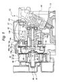
- Fig. 1 is a cross sectional view showing a cylinder head according to an embodiment of the invention.
- Fig. 2 is a partially broken, front view showing the cylinder head according to the embodiment.
- Fig. 3 is a view showing the embodiment on a right side of Fig. 2.
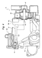
- Fig. 4 is a partially broken, front view showing a state, in which an AIS according to the embodiment is arranged.
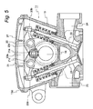
- Fig. 5 is a cross sectional view showing intake and exhaust valves according to the embodiment.
- Fig. 6 is a plan view showing the cylinder head according to the embodiment.
- Fig. 7 is a side view showing the cylinder head according to the embodiment.
- In addition, the
reference numeral 11 in the drawings denotes an engine, 13 a cylinder head, 13a insertion holes, 13b an accommodation chamber, 13c a roof wall, 13d a mating surface, 13e an accommodation chamber side recess, 13f a plug-side recess, 13g an accommodation-chamber opening, 13h an opening, 16 a camshaft, 17 a sprocket (rotating member), 19 a cam chain (wrapping transmission belt), 22 intake valves, 23 exhaust valves, 27 a head cover, 31 stud bolts (head clamping members), and 32 clamping bolts (head clamping members). - An embodiment of the invention will be described below.
- Figs. 1 to 7 show the embodiment of the invention.
- First, the constitution is described, and the
reference numeral 11 in Fig. 1 denotes a single cylinder, four-cycle, four-valve engine provided on a motorcycle, theengine 11 comprising acylinder head 13 fixed to a cylinder block (illustration of which is omitted). - As shown in Fig. 1, a
camshaft 16 is rotatably provided on thecylinder head 13 throughbearings sprocket 17 as a "rotating member" is mounted to an end of thecamshaft 16 by means of abolt 18. A cam chain 19 as a "wrapping transmission belt" is trained around thesprocket 17, so that a drive force from a crank shaft is transmitted to thesprocket 17 and thecamshaft 16 through the cam chain 19. - The
camshaft 16 is formed with intake andexhaust cam portions 16a, and one ends 20a, 21a of anintake rocker arm 20 and anexhaust rocker arm 21 are caused to abut against thecam portions 16a while theother ends 20b, 21b are caused to abut againstintake valves 22 andexhaust valves 23, as shown in Fig. 5. Thus, when thecamshaft 16 is rotated, therespective rocker arms shafts respective valves intake passage 24 and anexhaust valve 25. - The
intake valves 22 and theexhaust valves 23, respectively, are provided two, that is, four in total, an opening 13h is formed above theintake valves 22 and theexhaust valves 23, and ahead cover 27 as a "cover" is detachably mounted on the opening 13h by means of mount screws 28 (see Figs. 1 and 6) . - Also,
stud bolts 31 and clampingbolts 32, which serve as "head clamping members", respectively, are arranged in two locations on both sides of thecamshaft 16 in the opening 13h as shown in Fig. 6, so that thecylinder head 13 is mounted to a cylinder block by means of thestud bolts 31 and theclamping bolts 32. - More specifically, the
stud bolts 31 as "clamping bolts" are inserted into and fixed to insertion holes formed on the cylinder block whereby thestud bolts 31 are provided to project from the cylinder block. Thestud bolts 31 are inserted intoinsertion holes 13a of thecylinder head 13 to be arranged in parallel to an axis of a cylinder. Theclamping nuts 32 are screwed onto thestud bolts 31 whereby thecylinder head 13 is mounted on the cylinder block. - By removing the
head cover 27, theclamping nuts 32 are exposed and can be attached or removed, and by removing theclamping nuts 32, thecylinder head 13 can be removed from the cylinder block. - On the other hand, as shown in Fig. 1, a
breather rotating body 36 of abreather device 35 is mounted to thesprocket 17 fixed to a left end of thecamshaft 16 in the figure, and a breatherstationary body 37 is provided in opposition to thebreather rotating body 36. Also, a turningmember 40 of adecompression device 39 is arranged in thebreather rotating body 36 to be able to turn on a turningshaft 41, and the turningmember 40 is turned due to centrifugal forces generated when thesprocket 17 is rotated. - The
sprocket 17, thebreather device 35, etc. are accommodated in anaccommodation chamber 13b of thecylinder head 13, and aroof wall 13c of theaccommodation chamber 13b is formed integral with thecylinder head 13. Theaccommodation chamber 13b is formed adjacent to the opening 13h, an opened surface of the opening 13h is set to be in a lower position than an upper end of theroof wall 13c, and theroof wall 13c is arcuate in shape as viewed along thecamshaft 16 to have a larger diameter than that of thesprocket 17. - Amating
surface 13d on a peripheral portion of the opening 13h, which mates with thehead cover 27 for opening and closing of the opening 13h, is formed with an accommodation chamber side recess 13e positioned to correspond to a position on a side of theaccommodation chamber 13b, in which thesprocket 17 is arranged, the recess being recessed toward a center of the opening. Thestudbolts 31 and theclamping nuts 32 are arranged inpositions on both sides of the accommodation chamber side recess 13e. - Also, a plug-
side recess 13f is formed on a side of themating surface 13d opposed to theaccommodation chamber 13b to be recessed toward a center of the opening, and aspark plug 43 is arranged in the plug-side recess 13f. - Further, a
mount surface 13i is formed integrally on themating surface 13d as shown in Figs. 4 and 6, and an AIS (air induction system) 50 is mounted on themount surface 13i. - Moreover, an accommodation-chamber opening 13g is formed laterally of the
accommodation chamber 13b, and afitting portion 48a of a water-pump housing 48 of awater pump device 47 is fitted into and mounted to the accommodation-chamber opening 13g in a sealed state. Thewater pump device 47 comprises animpeller shaft 45 and animpeller 46, and theimpeller shaft 45 is fitted into thebolt 18 mounted to thecamshaft 16 whereby theimpeller 46 is rotated as thecamshaft 16 rotates. - With such construction, the
cylinder head 13 can be enhanced in strength by forming theroof wall 13c of theaccommodation chamber 13b, in which thesprocket 17 is accommodated, integral with thecylinder head 13. Besides, since it is possible to ensure stiffness for thecylinder head 13 as described above, thecylinder head 13 can be decreased in height by forming the opened surface of the opening 13h in a lower position than an upper end of theroof wall 13c. That is, when the opening 13h is formed contiguous to theaccommodation chamber 13b, stiffness is decreased, so that there is a need of providing a separate reinforcement plate on the upper surface of the opening 13h and when thehead cover 27 is fixed thereon, thecylinder head 13 will be increased in height. In contrast, according to the invention, since theroof wall 13c is integrally formed to enhance the stiffness of thecylinder head 13, there is no need of providing any separate reinforcement plate, and since the opening 13h is formed in a lower position than theroof wall 13c, thecylinder head 13 can be decreased in height even in the case where thehead cover 27 is mounted on the opening 13h. - Also, since the
accommodation chamber 13b is formed with the accommodation-chamber opening 13g laterally of thesprocket 17 and even in the case where the accommodation-chamber opening 13g is adapted to be closed by the water-pump housing (closure member) 48, theroof wall 13c is formed integral with thecylinder head 13, a peripheral edge (mating surface) of the accommodation-chamber opening 13g will not be shifted midway but can surely come into contact with a mating surface of thefitting portion 48a of the water-pump housing 48 to ensure the sealing quality. - That is, if the
roof wall 13c were separate from thecylinder head 13, the peripheral edge (sealed portion) of the accommodation-chamber opening 13g would become discontinuous, so that there is a fear that shift, poor sealing, or the like is generated between the sealed portion and theroof wall 13c due to error in molding, assembling, or the like. In contrast, according to the invention, theroof wall 13c is formed integral with thecylinder head 13 to eliminate such fear of generation of poor sealing, or the like. - Further, since the opened surface of the opening 13h is formed on the same plane, it can be formed more easily than the case where a plurality of openings having different inclinations should be formed.
- Moreover, the
stud bolts 31 can be made short and stable in axial forces by arranging thestud bolts 31 and theclamping nuts 32 inside the opening 13h, and since thestud bolts 31 and theclamping nuts 32 do not project above thehead cover 27, theengine 11 can be decreased in height. Also, by removing thehead cover 27, it is possible to perform tappet adjustment and to attach or remove thestud bolts 31 and theclamping nuts 32, thus enabling attaching or removing thecylinder head 13 from the cylinder block. - Also, the
mating surface 13d on the peripheral edge of the opening 13h is recessed toward the center of the opening 13h in a position corresponding to a position, in which thesprocket 17 on the side of theaccommodation chamber 13b is arranged, to form the accommodation chamber side recess 13e, so that thesprocket 17 can be made close to therespective valves camshaft 16. - Further, by arranging the
spark plug 43 in the plug-side recess 13f about themating surface 13d on the peripheral edge of the opening 13h, thespark plug 43 can be arranged between therespective valves cylinder head 13 can be made further compact in width along thecamshaft 16. - Moreover, since the
intake valves 22 and theexhaust valves 23 face outside from inside thesingle opening 13h, adjustment of both theintake valves 22 and theexhaust valves 23 can be made by removing thehead cover 27, which covers the opening 13h. - Besides, since the
roof wall 13c is arcuate in shape as viewed along thecamshaft 16 to have a larger diameter than that of thesprocket 17, a useless space in theroof wall 13c can be made as small as possible in a state, in which thesprocket 17 is arranged in theroof wall 13c, so that it is possible to make theroof wall 13c as compact as possible in external shape. - Also, as shown in Figs. 4 and 6, the
mating surface 13d is formed integral with themount surface 13i, to which the AIS (air induction system) 50 is mounted, so that themount surface 13i can be easily formed, and by arranging theAIS 50 on thehead cover 27, theAIS 50 can be simply arranged only by mounting thehead cover 27 on themating surface 13d. - By the way, the opened surface of the
opening 13h can be inclined relative to an axis of the cylinder as indicated by a two-dot chain line A in Fig. 1 in a manner to be lowered on an opposite side to theroof wall 13c. With such arrangement, a tool is inserted from theopening 13h to enable performing the attaching or removing operation from laterally of thestud bolts 31 and the clampingnuts 32, and so the operation of maintenance is easy to perform. - In addition, while the embodiment applies the invention to the
engine 11 for motorcycles, the invention is of course applicable to engines for other uses. Also, engines are not limited to single cylinder, four-valve ones but may be of other type. Further, while thesprocket 17 is adopted as a "rotating member", it is not limitative but it is possible to use a pulley in place of thesprocket 17 and a belt as a "wrapping transmission belt" in place of the cam chain 19. Also, it is possible to adopt gears in place of thesprocket 17 so that a drive force from the crank shaft can be transmitted by means of a plurality of gears. - While the invention has been described in detail with reference to the specific embodiment, it is apparent to those skilled in the art that various changes and modifications can be made without departing from the spirit and scope of the invention.
- The present application is based on Japanese Patent Application (Patent Application No. 2003-195211) filed on July 10, 2003 and Japanese Patent Application (Patent Application No. 2004-176406) filed on June 15, 2004, contents of which are incorporate herein for reference.
- According to the invention, the cylinder head can be enhanced in strength by forming the roof wall of the accommodation chamber, in which the rotating member is accommodated, integral with the cylinder head. Besides, since it is possible to ensure stiffness for the cylinder head as described above, the cylinder head can be decreased in height by forming the opened surface of the opening in a lower position than an upper end of the roof wall. That is, when the opening is formed contiguous to an upper portion of the accommodation chamber without forming the roof wall integral with the cylinder head, stiffness is decreased, so that there is a need of providing a separate reinforcement plate on the upper surface of the opening and since the head cover is fixed thereon, the cylinder head will be increased in height. In contrast, according to the invention, since the roof wall is integrally formed to enhance the stiffness of the cylinder head, there is no need of providing any separate reinforcement plate, and since the opening is formed in a lower position than the roof wall, the cylinder head can be decreased in height even in the case where the head cover is mounted on the opening.
- Also, since the accommodation chamber is formed with the accommodation-chamber opening laterally of the rotating member and even in the case where the accommodation-chamber opening is adapted to be closed by the closure member, the roof wall is formed integral with the cylinder head, a peripheral edge (mating surface) of the accommodation-chamber opening will not be shifted midway but can be caused to surely abut against a mating surface of the closure member to ensure the sealing quality.
- Further, since the opened surface is formed on the same plane, it can be formedmore easily than the case where a plurality of openings having different inclinations should be formed.
- Moreover, according to the invention, the head clamping members are arranged inside the opening whereby the head clamping members can be positionally lowered, so that the head clamping members (for example, clamping bolts) can be made short and stable in axial forces, and since the head clamping members do not project above the head cover, the engine can be decreased in height. Also, by removing the head cover, it is possible to perform tappet adjustment and to attach or remove the head clamping members, thus enabling attaching or removing the cylinder head from the cylinder block.
- Also, the accommodation chamber side recess is formed on the mating surface on the peripheral edge of the opening to be positioned in a position corresponding to a position, in which the rotating member on the side of the accommodation chamber is arranged, so that the rotating member can be made close to the valves to make the cylinder head further compact in width along the camshaft.
- Also, by arranging the spark plug in the plug-side recess about the mating surface on the peripheral edge of the opening, which recess is recessed toward the center of the opening, the spark plug can be arranged between the respective valves to stand further upright, so that the cylinder head can be made further compact in width along the camshaft.
- Also, since the intake valves and the exhaust valves face outside from inside the single opening, adjustment of both the intake valves and the exhaust valves can be made by removing the head cover, which covers the opening.
- Also, since the opened surface of the opening is inclined, a tool is inserted from the opening to enable performing the attaching or removing operation from laterally of the head clamping members, and so maintenance is easy to perform.
- Also, since the roof wall is formed to be arcuate corresponding to the circular-shaped rotating member, a useless space in the roof wall can be made as small as possible in a state, in which the rotating member is arranged in the roof wall, it is possible to make the roof wall as compact as possible in external shape.
Claims (8)
- An engine, characterized in that a rotating member is fixed to a camshaft provided on a cylinder head, a drive force from a crank shaft is transmitted to the rotating member, and a roof wall of an accommodation chamber, in which the rotating member is accommodated, is formed integral with the cylinder head, and that an opening is formed on an upper surface portion of the cylinder head to be adjacent to the roof wall, intake and exhaust valves are constructed to face outside from the opening, and an opened surface of the opening is positioned in a lower position than an upper end of the roof wall and on the same plane.
- The engine according to claim 1, wherein head clamping members for fixation of the cylinder head to a cylinder block are provided inside the opening, and the head clamping members are arranged to face outside through the opening.
- An engine, characterized in that a rotating member is fixed to a camshaft provided on a cylinder head, a wrapping transmission belt for transmission of a drive force from a crank shaft is trained around the rotatingmember, and an accommodation chamber, which comprises a roof wall and in which the rotating member is accommodated, is formed in the cylinder head, and
that an opening is formed on an upper surface portion of the cylinder head to be adjacent to the roof wall, head clamping members for fixation of the cylinder head to a cylinder block are constructed to look out from the opening, and an opened surface of the opening is formed in a lower position than an upper end of the roof wall. - The engine according to any one of claims 1 to 3, wherein a mating surface on a peripheral portion of the opening, which mates with a head cover for covering the opening, is recessed toward a center of the opening in a position corresponding to a position on a side of the accommodation chamber, in which the rotating member is arranged, whereby an accommodation chamber side recess is formed.
- The engine according to any one of claims 1 to 3, wherein an opposite side of a mating surface on a peripheral portion of the opening, which mates with a head cover for covering the opening, to the accommodation chamber is recessed toward a center of the opening to form a plug-side recess, and a spark plug is arranged in the plug-side recess.
- The engine according to any one of claims 1 to 3, wherein the intake and exhaust valves face outside from the single opening.
- The engine according to any one of claims 1 to 3, wherein the opened surface of the opening is inclined relative to an axis of a cylinder.
- The engine according to any one of claims 1 to 3, wherein the roof wall is arcuate in shape as viewed along the camshaft to have a larger diameter than that of the rotating member.
Applications Claiming Priority (3)
| Application Number | Priority Date | Filing Date | Title |
|---|---|---|---|
| JP2003195211 | 2003-07-10 | ||
| JP2004176406 | 2004-06-15 | ||
| PCT/JP2004/009899 WO2005005814A1 (en) | 2003-07-10 | 2004-07-06 | Engine |
Publications (2)
| Publication Number | Publication Date |
|---|---|
| EP1645745A1 true EP1645745A1 (en) | 2006-04-12 |
| EP1645745A4 EP1645745A4 (en) | 2009-06-10 |
Family
ID=34067333
Family Applications (1)
| Application Number | Title | Priority Date | Filing Date |
|---|---|---|---|
| EP04747367A Withdrawn EP1645745A4 (en) | 2003-07-10 | 2004-07-06 | Engine |
Country Status (3)
| Country | Link |
|---|---|
| EP (1) | EP1645745A4 (en) |
| JP (1) | JP4476221B2 (en) |
| WO (1) | WO2005005814A1 (en) |
Cited By (1)
| Publication number | Priority date | Publication date | Assignee | Title |
|---|---|---|---|---|
| US20220341372A1 (en) * | 2019-09-27 | 2022-10-27 | Deutz Aktiengesellschaft | Cylinder head including a cast-in water pump and integrated thermostat |
Family Cites Families (2)
| Publication number | Priority date | Publication date | Assignee | Title |
|---|---|---|---|---|
| JP3589328B2 (en) * | 1996-01-12 | 2004-11-17 | 本田技研工業株式会社 | Assembly structure of internal combustion engine |
| JP4270727B2 (en) * | 2000-08-03 | 2009-06-03 | 本田技研工業株式会社 | Engine intake system |
-
2004
- 2004-07-06 JP JP2005511557A patent/JP4476221B2/en not_active Expired - Lifetime
- 2004-07-06 WO PCT/JP2004/009899 patent/WO2005005814A1/en not_active Ceased
- 2004-07-06 EP EP04747367A patent/EP1645745A4/en not_active Withdrawn
Non-Patent Citations (2)
| Title |
|---|
| No further relevant documents disclosed * |
| See also references of WO2005005814A1 * |
Cited By (2)
| Publication number | Priority date | Publication date | Assignee | Title |
|---|---|---|---|---|
| US20220341372A1 (en) * | 2019-09-27 | 2022-10-27 | Deutz Aktiengesellschaft | Cylinder head including a cast-in water pump and integrated thermostat |
| US11788487B2 (en) * | 2019-09-27 | 2023-10-17 | Deutz Aktiengesellschaft | Cylinder head including a cast-in water pump and integrated thermostat |
Also Published As
| Publication number | Publication date |
|---|---|
| EP1645745A4 (en) | 2009-06-10 |
| JPWO2005005814A1 (en) | 2006-08-24 |
| WO2005005814A1 (en) | 2005-01-20 |
| JP4476221B2 (en) | 2010-06-09 |
Similar Documents
| Publication | Publication Date | Title |
|---|---|---|
| JP4036401B2 (en) | 4-cycle engine with variable valve timing system | |
| EP2202392A2 (en) | Water pump attachment structure of water-cooled internal combustion engine | |
| US6591930B2 (en) | Valve cover | |
| JP2002276523A (en) | Plug pipe mounting structure for internal combustion engine | |
| GB2230560A (en) | Engine cylinder head idler mounting housing | |
| EP1403497B1 (en) | Camshaft bearing structure for over-head camshaft type internal combustion engine | |
| CN100480497C (en) | Engine | |
| US7878165B2 (en) | Engine valve operating system | |
| CN100580227C (en) | Rotation stop device for rocker arm shaft in valve gear of internal combustion engine | |
| US6202617B1 (en) | Cylinder head of a DOHC type engine | |
| JP4476221B2 (en) | engine | |
| JP3327322B2 (en) | 4 cycle engine with variable valve timing device | |
| JP3272245B2 (en) | Chain cover structure of 4-cycle engine | |
| JP4124301B2 (en) | Vehicle engine | |
| JP5205117B2 (en) | Engine and vehicle equipped with the engine | |
| JP2002276308A (en) | Camshaft support structure for 4-cycle engine | |
| KR20050076611A (en) | Subsidiary mechanism attachment structure of internal combustion engine | |
| JP3589328B2 (en) | Assembly structure of internal combustion engine | |
| JP3591744B2 (en) | Cam cap structure of DOHC engine | |
| JP4036402B2 (en) | 4-cycle engine cylinder head structure | |
| JP2004068822A (en) | Case member mounting structure | |
| JP2761388B2 (en) | 4-cycle engine head cover mounting structure | |
| JP3827085B2 (en) | Internal combustion engine head cover | |
| JP3117765B2 (en) | Valve train for 5-valve engine | |
| JP3602552B2 (en) | Engine cylinder fastening structure |
Legal Events
| Date | Code | Title | Description |
|---|---|---|---|
| PUAI | Public reference made under article 153(3) epc to a published international application that has entered the european phase |
Free format text: ORIGINAL CODE: 0009012 |
|
| 17P | Request for examination filed |
Effective date: 20060117 |
|
| AK | Designated contracting states |
Kind code of ref document: A1 Designated state(s): AT BE BG CH CY CZ DE DK EE ES FI FR GB GR HU IE IT LI LU MC NL PL PT RO SE SI SK TR |
|
| DAX | Request for extension of the european patent (deleted) | ||
| A4 | Supplementary search report drawn up and despatched |
Effective date: 20090512 |
|
| STAA | Information on the status of an ep patent application or granted ep patent |
Free format text: STATUS: THE APPLICATION HAS BEEN WITHDRAWN |
|
| 18W | Application withdrawn |
Effective date: 20100521 |