EP1645734A1 - Moteur à combustion interne comportant un injecteur de carburant a jets optimisés - Google Patents
Moteur à combustion interne comportant un injecteur de carburant a jets optimisés Download PDFInfo
- Publication number
- EP1645734A1 EP1645734A1 EP05300798A EP05300798A EP1645734A1 EP 1645734 A1 EP1645734 A1 EP 1645734A1 EP 05300798 A EP05300798 A EP 05300798A EP 05300798 A EP05300798 A EP 05300798A EP 1645734 A1 EP1645734 A1 EP 1645734A1
- Authority
- EP
- European Patent Office
- Prior art keywords
- jet
- injector
- arc
- length
- jets
- Prior art date
- Legal status (The legal status is an assumption and is not a legal conclusion. Google has not performed a legal analysis and makes no representation as to the accuracy of the status listed.)
- Granted
Links
Images

Classifications
-
- F—MECHANICAL ENGINEERING; LIGHTING; HEATING; WEAPONS; BLASTING
- F02—COMBUSTION ENGINES; HOT-GAS OR COMBUSTION-PRODUCT ENGINE PLANTS
- F02B—INTERNAL-COMBUSTION PISTON ENGINES; COMBUSTION ENGINES IN GENERAL
- F02B23/00—Other engines characterised by special shape or construction of combustion chambers to improve operation
- F02B23/02—Other engines characterised by special shape or construction of combustion chambers to improve operation with compression ignition
- F02B23/06—Other engines characterised by special shape or construction of combustion chambers to improve operation with compression ignition the combustion space being arranged in working piston
- F02B23/0696—W-piston bowl, i.e. the combustion space having a central projection pointing towards the cylinder head and the surrounding wall being inclined towards the cylinder wall
-
- F—MECHANICAL ENGINEERING; LIGHTING; HEATING; WEAPONS; BLASTING
- F02—COMBUSTION ENGINES; HOT-GAS OR COMBUSTION-PRODUCT ENGINE PLANTS
- F02B—INTERNAL-COMBUSTION PISTON ENGINES; COMBUSTION ENGINES IN GENERAL
- F02B23/00—Other engines characterised by special shape or construction of combustion chambers to improve operation
- F02B23/02—Other engines characterised by special shape or construction of combustion chambers to improve operation with compression ignition
- F02B23/06—Other engines characterised by special shape or construction of combustion chambers to improve operation with compression ignition the combustion space being arranged in working piston
- F02B23/0645—Details related to the fuel injector or the fuel spray
- F02B23/066—Details related to the fuel injector or the fuel spray the injector being located substantially off-set from the cylinder centre axis
-
- F—MECHANICAL ENGINEERING; LIGHTING; HEATING; WEAPONS; BLASTING
- F02—COMBUSTION ENGINES; HOT-GAS OR COMBUSTION-PRODUCT ENGINE PLANTS
- F02B—INTERNAL-COMBUSTION PISTON ENGINES; COMBUSTION ENGINES IN GENERAL
- F02B23/00—Other engines characterised by special shape or construction of combustion chambers to improve operation
- F02B23/02—Other engines characterised by special shape or construction of combustion chambers to improve operation with compression ignition
- F02B23/06—Other engines characterised by special shape or construction of combustion chambers to improve operation with compression ignition the combustion space being arranged in working piston
- F02B23/0645—Details related to the fuel injector or the fuel spray
- F02B23/0669—Details related to the fuel injector or the fuel spray having multiple fuel spray jets per injector nozzle
-
- F—MECHANICAL ENGINEERING; LIGHTING; HEATING; WEAPONS; BLASTING
- F02—COMBUSTION ENGINES; HOT-GAS OR COMBUSTION-PRODUCT ENGINE PLANTS
- F02M—SUPPLYING COMBUSTION ENGINES IN GENERAL WITH COMBUSTIBLE MIXTURES OR CONSTITUENTS THEREOF
- F02M61/00—Fuel-injectors not provided for in groups F02M39/00 - F02M57/00 or F02M67/00
- F02M61/16—Details not provided for in, or of interest apart from, the apparatus of groups F02M61/02 - F02M61/14
- F02M61/18—Injection nozzles, e.g. having valve seats; Details of valve member seated ends, not otherwise provided for
- F02M61/1806—Injection nozzles, e.g. having valve seats; Details of valve member seated ends, not otherwise provided for characterised by the arrangement of discharge orifices, e.g. orientation or size
-
- F—MECHANICAL ENGINEERING; LIGHTING; HEATING; WEAPONS; BLASTING
- F02—COMBUSTION ENGINES; HOT-GAS OR COMBUSTION-PRODUCT ENGINE PLANTS
- F02B—INTERNAL-COMBUSTION PISTON ENGINES; COMBUSTION ENGINES IN GENERAL
- F02B2275/00—Other engines, components or details, not provided for in other groups of this subclass
- F02B2275/14—Direct injection into combustion chamber
-
- Y—GENERAL TAGGING OF NEW TECHNOLOGICAL DEVELOPMENTS; GENERAL TAGGING OF CROSS-SECTIONAL TECHNOLOGIES SPANNING OVER SEVERAL SECTIONS OF THE IPC; TECHNICAL SUBJECTS COVERED BY FORMER USPC CROSS-REFERENCE ART COLLECTIONS [XRACs] AND DIGESTS
- Y02—TECHNOLOGIES OR APPLICATIONS FOR MITIGATION OR ADAPTATION AGAINST CLIMATE CHANGE
- Y02T—CLIMATE CHANGE MITIGATION TECHNOLOGIES RELATED TO TRANSPORTATION
- Y02T10/00—Road transport of goods or passengers
- Y02T10/10—Internal combustion engine [ICE] based vehicles
- Y02T10/12—Improving ICE efficiencies
Definitions
- the invention relates to a direct injection internal combustion engine of the type comprising a multi-jet fuel injector.
- the invention relates more particularly to a direct injection internal combustion engine, comprising a cylinder head which carries at least one fuel injector provided at its free axial end with an injection nozzle comprising a number "i" of injection holes. which are arranged annularly in at least one row to atomize the fuel in the form of a web consisting injection of "i" J i asymmetric fuel jets directly inside an associated combustion bowl which is made in the upper face of a piston of the engine, in which each jet J i travels, from a point I of the injector to a point of intersection M i of the spray axis B of the jet J i with the wall of the bowl, a length L i , and wherein the distance between two points of intersection M i , M i + 1 of two adjacent jets J i , J i + 1 is defined by an arc corresponding to Arc Ji, Jj + 1 .
- Such improvements can in particular be obtained by acting on the quality of the mixture between the intake gas and the fuel so as to produce in the combustion chamber of the engine a mixture which is substantially homogeneous.
- the injector is arranged in an eccentric position with respect to the vertical axis of the cylinder, in particular because of the presence of the intake and exhaust valves.
- the nozzle or nose of the injector is then generally brought closer to the axis of the cylinder, by tilting the general axis of the injector relative to the axis of the cylinder.
- Document FR-A-2.844.012 describes and represents in particular in FIG. 1 an example of an internal combustion engine comprising an eccentric fuel injector, that is to say an injector which is on the one hand radially offset by relative to the axis of the cylinder and, on the other hand, inclined so that the general axis of the injector forms an angle with the axis of the cylinder.
- an eccentric fuel injector that is to say an injector which is on the one hand radially offset by relative to the axis of the cylinder and, on the other hand, inclined so that the general axis of the injector forms an angle with the axis of the cylinder.
- the various injected fuel jets are then asymmetrical, in particular the different fuel jets travel in different lengths before coming into contact with the internal wall of the combustion bowl.
- this causes an imbalance between the distribution of fuel and intake gases and consequently affects the quality of the mixture which is not optimal, does not allow to obtain a mixture as homogeneous as desired.
- the main phenomena which combine and which make it possible to obtain such a substantially homogeneous mixture are essentially the spraying of the fuel and the movements of air in the middle of the charge of the intake gases and those caused by fuel injection.
- the injection nozzle of the injector has injection holes which are distributed annularly in a regular manner around the nozzle in at least one row of holes so that the acute angles included between each of the main spray axes of the fuel jets are all equal to each other.
- each jet is only assimilated to a straight line corresponding to the main axis of spray of the fuel jet, without taking into account the action of the gas movements of admission on the jets and in the "iso-angle" method without considering the length traveled by each jet before coming into contact with the wall of the bowl.
- the invention therefore proposes an internal combustion engine comprising a fuel injector whose characteristics of the injection holes are determined so as to take into account this winding effect of the fuel jets to optimize the distribution of the jets and therefore the obtaining a substantially homogeneous mixture.
- the invention proposes an internal combustion engine of the type described above, characterized in that the holes of the injection nozzle are made so that the sum S of the length L i and the arc Ji, Ji + 1 of each jet J i is equal to a constant.
- the sum S is still called the "free length" of the jet.
- the length L i of each jet J i is in particular determined by the diameter or the section of the corresponding hole of the injection nozzle.
- the fuel of each injection jet mixes optimally with the intake gases.
- each jet is susceptible, in particular under the action of the swirl effect, to develop in an equivalent manner, that is to say with an identical “free length”, by "winding" according to the direction of the swirling movement which allows to obtain an optimal distribution of the fuel jets although they are dissymmetrical and thus a substantially homogeneous mixture.
- the engine comprises means for producing on admission a swirling movement ordered of the "swirl" type.
- the exchange between the injected fuel and the intake gases of the internal combustion engine is improved and the engine performance is increased while reducing the formation of pollutants, such as soot and the like. unburned hydrocarbons constituting the black fumes at the exhaust outlet.
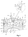
- FIG. 1 shows diagrammatically a part of an internal combustion engine 10 of the direct injection type.
- FIG. 1 more particularly represents a cylinder 12 with a vertical X-X axis and a piston 14 able to slide axially in the cylinder 12 of the engine 10 by describing a reciprocating movement.
- the piston 14 has a head 16 in its upper section and an axial skirt 18 in its lower section.
- the outer cylindrical wall 20 of the head 16 has peripheral annular grooves 22 which receive segments 24.
- the piston 14 has in its upper face 26 a cavity or combustion bowl 28 which defines the lower part of a combustion chamber 30 and whose upper part is delimited by the yoke 32 of the engine.
- the combustion bowl 28 here has a symmetry of revolution about a vertical axis which coincides with the axis XX of the cylinder 12.
- the combustion bowl 28 preferably comprises a peripheral annular groove 34 and a central boss 36, here generally shaped conical cap.
- the cylinder head 32 comprises at least one air intake duct which opens out through an inlet orifice closed by an intake valve (not shown) in the combustion chamber 30, and at least one exhaust gas duct. burned out through an outlet orifice intended to be closed by an exhaust valve (not shown) in the combustion chamber 30.
- the yoke 32 carries a fuel injector 38 whose nozzle or injection nose 40 opens directly into the combustion chamber 30 of the engine.
- the injection nozzle 40 of the injector 38 has a number "i" of holes 42 which are here arranged axially in a single row and distributed annularly with respect to the general axis A of the injector around the nozzle 40.
- the number "i" of injection holes 42 is greater than or equal to 6.
- the holes 42 of the injection nozzle 40 are angularly distributed regularly around the main axis A of the injector 38.
- the fuel is thus sprayed by the holes 42 in the form of a globally frustoconical injection ply which consists of all the jets J i corresponding to the number "i" of holes 42.
- the injection ply has a determined "ply angle" corresponding to the opening at the top of the cone and which depends on the type of injector 38 and associated combustion bowl 28.
- each jet J i is located near a point I which is generally located in the center of the nozzle 40 of the injector 38, on the general axis A of the injector.
- each jet J travels from the point I of the injector 38 to a point intersection M i of the main spray axis B of the jet J i with the wall 44 of the bowl 28, a line segment of length L i .
- the fuel is injected in the form of an injection ply determined by six jets J 1 to J 6 asymmetrical and which are generally straight along their respective spraying axes B.
- the injection nozzle 40 thus comprises six corresponding holes 42 which are arranged annularly and distributed axially in a single row 46 forming a ring.
- each jet J i Since the jets J i are dissymmetrical, each jet J i has a specific length L i which is specific to it and which is a function of numerous parameters and more particularly of the radius of the combustion bowl 28.
- Each hole 42 is here circular and of constant section or of the same diameter, but in a variant the holes are likely to have different diameters or other shapes, such as frustoconical shapes, and to extend along a rectilinear main axis or curved.
- the distance between two points of intersection M i , M i + 1 respectively of a first jet J i and a second jet J i + 1 which is adjacent to it, for example according to the direction of the swirling motion of "swirl" , is defined by an arc either here Arc Ji, Ji + 1 .
- the set of points of intersection M1 to M6 of the main axis of each jet J i along the spray axis B with the wall 44 of the bowl 28 are located at the same axial dimension along the axis XX cylinder 12, that is to say in the same horizontal plane orthogonal to the axis XX.
- each of the points M1 to M6 can take all possible values along the wall 44 of the bowl 28 so that each jet J i comes into contact with the high velocity intake gases.
- the holes 42 of the injection nozzle 40 are made in such a way that the sum S of the length L i and of the arc Ji, Ji + 1 of each jet J i is equal to a constant.
- Said length L i of a jet J i is the length of the line segment which connects, along the main axis B of the jet J i , the point I of the injector 38 to a point of intersection M i of said jet J i .
- the value of the acute angle (p Ji, Ji + 1 ) is thus different for each of the jets J 1 to J 6 , and corresponds for example, to the projection of FIG. 3, to " ⁇ " for the adjacent jets J 1 and J 2 or " ⁇ ” for the following consecutive jets J 2 and J 3 .
- the annular combustion bowl 28 is generally circular and here it is centered on the X-X axis of the cylinder in which the piston 14 slides.
- FIGS. 2 and 3 there is shown diagrammatically an injection plane P which is perpendicular to the axis XX of the cylinder 12 and which thus extends horizontally through all the points intersection M1 to M6 jets J 1 to J 6 .
- the injection plane P shown here generally has a circular shape delimited and passing through the set of points of intersection M1 to M6.
- fuel injection is advantageously carried out simultaneously by all the injection holes when the nozzle comprises a single row and that the injection takes place in the form of a number "i" of sprayed fuel jets forming an injection ply 48 determined.
- the injection is preferably performed when the piston 14 substantially reaches a position called top dead center (TDC).
- TDC top dead center
- the jet J 1 is thus injected by one of the holes 42 of the injection nozzle 40 along a main axis B and it traverses a length L1 corresponding to the line segment between the point I and the point of intersection M1 of the main axis B of the jet J 1 with the wall 44 of the combustion bowl 28.
- the arrow F indicates the direction of the swirling swirl movement in the combustion bowl 28 of the chamber 30.
- the jet J 2 is injected, simultaneously with the jet J 1 , by the consecutive hole 42 of the row 46, here along the arrow F, and along a main axis B of jet J 2 which thus travels a length L 2 corresponding generally to the line segment starting from point I and terminating at the point of intersection M2 of the main axis B of the jet J 2 with the wall 44 of the combustion bowl 28.
- the length to travel from the point M1 to join the adjacent point M2 corresponds, here following the wall 44 of the combustion bowl 28, to an arc, more precisely to the arc J1, J2 .
- the holes 42 in particular the axial and / or angular position of each hole 42, have to be determined in such a way that the free length of each of the jets J i is identical in order to guarantee a distribution. fuel and a homogeneous mixture of the fuel with the intake gases.
- the angle p J1, J2 corresponds to the angle between the projections of the adjacent jets J 1 and J 2 respectively corresponding to the length portions L 1 and L 2.
- the point corresponds to the projection of the point I of the injection nozzle 40 jets J 1 to J 6 .
- the diameter of each hole 42 of the injection nozzle 40 is preferably determined as a function of the length L i of the jet J i .
Landscapes
- Engineering & Computer Science (AREA)
- Chemical & Material Sciences (AREA)
- Combustion & Propulsion (AREA)
- Mechanical Engineering (AREA)
- General Engineering & Computer Science (AREA)
- Fuel-Injection Apparatus (AREA)
- Combustion Methods Of Internal-Combustion Engines (AREA)
- Electrical Control Of Air Or Fuel Supplied To Internal-Combustion Engine (AREA)
Abstract
Description
- L'invention concerne un moteur à combustion interne à injection directe, du type comportant un injecteur de carburant multi jets.
- L'invention concerne plus particulièrement un moteur à combustion interne à injection directe, comportant une culasse qui porte au moins un injecteur de carburant muni à son extrémité axiale libre d'une buse d'injection comportant un nombre "i" de trous d'injection qui sont agencés annulairement suivant au moins une rangée pour pulvériser le carburant sous la forme d'une nappe d'injection constituée des "i" jets Ji dissymétriques de carburant directement à l'intérieur d'un bol de combustion associé qui est réalisé dans la face supérieure d'un piston du moteur, dans lequel chaque jet Ji parcourt, depuis un point I de l'injecteur jusqu'à un point d'intersection Mi de l'axe de pulvérisation B du jet Ji avec la paroi du bol, une longueur Li, et dans lequel la distance entre deux points d'intersection Mi, Mi+1 de deux jets adjacents Ji, Ji+1 est définie par un arc correspondant à ArcJi, Jj+1.
- On connaît de nombreux exemples de moteurs de véhicules automobiles de ce type dont on cherche tout particulièrement à améliorer les performances en réduisant parallèlement d'une part leur consommation et, d'autre part, l'émission de polluants, tels que les oxydes d'azote (NOx) et les particules de suies.
- De telles améliorations peuvent notamment être obtenues en agissant sur la qualité du mélange entre les gaz d'admission et le carburant de manière à réaliser dans la chambre de combustion du moteur un mélange qui soit sensiblement homogène.
- Selon une conception conventionnelle connue d'un moteur à injection directe, l'injecteur est agencé dans une position excentrée par rapport à l'axe vertical du cylindre, notamment du fait de la présence des soupapes d'admission et d'échappement.
- Cependant, pour que l'injection de carburant soit effectuée le plus près possible de l'axe du cylindre dans lequel coulisse le piston, la buse ou nez de l'injecteur est alors généralement rapprochée de l'axe du cylindre, en inclinant l'axe général de l'injecteur par rapport à l'axe du cylindre.
- Le document FR-A-2.844.012 décrit et représente notamment à la figure 1, un exemple de moteur à combustion interne comportant un injecteur de carburant excentré, c'est-à-dire un injecteur qui est d'une part décalé radialement par rapport à l'axe du cylindre et, d'autre part, incliné de manière que l'axe général de l'injecteur forme un angle avec l'axe du cylindre.
- Lorsque l'injecteur est ainsi excentré, les différents jets de carburant injectés sont alors dissymétriques, en particulier les différents jets de carburant parcourent des longueurs différentes avant d'entrer en contact avec la paroi interne du bol de combustion. Or cela provoque un déséquilibre entre la répartition du carburant et des gaz d'admission et affecte par conséquent la qualité du mélange qui n'étant pas optimale, ne permet pas d'obtenir un mélange aussi homogène que souhaitée.
- Dans un moteur à injection directe, les phénomènes principaux qui se combinent et qui permettent d'obtenir un tel mélange sensiblement homogène sont essentiellement la pulvérisation du carburant et les mouvements d'air au milieu de la charge des gaz d'admission et ceux provoqués par l'injection du carburant.
- C'est la raison pour laquelle, on a notamment cherché à optimiser la répartition des jets dans le bol de combustion afin d'améliorer l'homogénéité du mélange du carburant avec les gaz d'admission.
- On connaît dans l'état de la technique différentes méthodes, telles que la méthode appelée "iso-angle", qui sont susceptibles de permettre de concevoir et de fabriquer un injecteur de carburant dans lequel la répartition des jets pulvérisés est optimisée pour une application donnée et en fonction d'un certain nombre de paramètres de fonctionnement déterminés, notamment de la chambre de combustion du moteur.
- Selon la méthode "iso-angle", la buse d'injection de l'injecteur comporte des trous d'injection qui sont répartis annulairement de manière régulière autour de la buse selon au moins une rangée de trous de telle sorte que les angles aigus compris entre chacun des axes principaux de pulvérisation des jets de carburant soient tous égaux entre eux.
- Dans les méthodes connues de l'état de la technique, chaque jet est uniquement assimilé à une droite correspondant à l'axe principal de pulvérisation du jet de carburant, sans qu'il soit tenu compte de l'action des mouvements des gaz d'admission sur les jets et dans la méthode "iso-angle" sans considérer la longueur parcourue par chacun des jets avant d'entrer en contact avec la paroi du bol.
- Or on a pu déterminer que les jets d'injection "s'enroulent" dans le bol de combustion sous l'action des mouvements des gaz d'admission, et plus particulièrement du mouvement de "swirl" qui se forme dans le bol de combustion autour d'un axe sensiblement confondu ou parallèle à l'axe du cylindre.
- L'invention propose donc un moteur à combustion interne comportant un injecteur de carburant dont les caractéristiques des trous d'injection sont déterminées de manière à prendre en compte cet effet d'enroulement des jets de carburant pour optimiser la répartition des jets et donc l'obtention d'un mélange sensiblement homogène.
- Dans ce but, l'invention propose un moteur à combustion interne du type décrit précédemment, caractérisé en ce que les trous de la buse d'injection sont réalisés de manière que la somme S de la longueur Li et de l'ArcJi, Ji+1 de chaque jet Ji soit égale à une constante.
- La somme S est encore appelée la "longueur libre" du jet.
- Avantageusement, la longueur Li de chaque jet Ji est notamment déterminée par le diamètre ou la section du trou correspondant de la buse d'injection.
- Selon d'autres caractéristiques de l'invention :
- ladite longueur Li est la longueur du segment de droite qui relie suivant l'axe de pulvérisation B du jet Ji le point I de l'injecteur 38 au un point d'intersection Mi ;
- l'ArcJi, Ji+1 est déterminé conformément à la relation :

- les trous de la buse d'injection sont répartis angulairement autour de l'axe principal A de l'injecteur de manière à ce que la somme S soit égale à une constante ;
- le diamètre de chaque trou de la buse d'injection est déterminé en fonction de la longueur Li du jet Ji ;
- Grâce à l'invention, le carburant de chaque jet d'injection se mélange de manière optimale avec les gaz d'admission.
- Plus précisément, chaque jet est susceptible, notamment sous l'action de l'effet de swirl, de se développer de manière équivalente, c'est-à-dire avec une "longueur libre" identique, en "s'enroulant" selon le sens du mouvement tourbillonnaire ce qui permet d'obtenir une répartition optimale des jets de carburant bien qu'ils soient dissymétriques et donc un mélange sensiblement homogène.
- Avantageusement, le moteur comporte des moyens pour produire à l'admission un mouvement tourbillonnaire ordonné du type « swirl ».
- Grâce à l'invention, on améliore l'échange entre le carburant injecté et les gaz d'admission du moteur à combustion interne et on augmente les performances du moteur tout en réduisant la formation de polluants, tels que les suies et autres hydrocarbures imbrûlés constituant les fumées noires en sortie d'échappement.
- D'autres caractéristiques et avantages de l'invention apparaîtront à la lecture de la description détaillée qui suit pour la compréhension de laquelle on se reportera aux figures annexées parmi lesquelles :
- la figure 1 est une vue schématique en coupe axiale qui représente un cylindre d'un moteur à combustion interne ;
- la figure 2 est une vue schématique en perspective de l'injecteur de la figure 1 dont les trous de la buse sont réalisés conformément à l'invention et qui représente la répartition des jets de longueur libre équivalente ;
- la figure 3 est une vue de dessus de la figure 2 sans l'injecteur qui représente la projection géométrique des jets dans un plan horizontal d'injection.
- On a représenté schématiquement à la figure 1, une partie d'un moteur à combustion interne 10 du type à injection directe.
- La figure 1 représente plus particulièrement un cylindre 12 d'axe X-X vertical et un piston 14 apte à coulisser axialement dans le cylindre 12 du moteur 10 en décrivant un mouvement de va-et-vient. Le piston 14 comporte une tête 16 dans son tronçon supérieur et une jupe axiale 18 dans son tronçon inférieur.
- La paroi cylindrique externe 20 de la tête 16 comporte des gorges annulaires périphériques 22 qui reçoivent des segments 24.
- Le piston 14 comporte dans sa face supérieure 26 une cavité ou bol de combustion 28 qui délimite la partie inférieure d'une chambre de combustion 30 et dont la partie supérieure est délimitée par la culasse 32 du moteur.
- Le bol de combustion 28 présente ici une symétrie de révolution autour d'un axe vertical qui est confondu avec l'axe X-X du cylindre 12.
- Le bol de combustion 28 comporte de préférence une gorge annulaire périphérique 34 et un bossage central 36, ici globalement en forme de calotte conique.
- La culasse 32 comporte au moins un conduit d'admission d'air qui débouche par un orifice d'entrée obturé par une soupape d'admission (non représentés) dans la chambre de combustion 30, et au moins un conduit d'échappement des gaz brûlés qui débouche par un orifice de sortie destiné à être obturé par une soupape d'échappement (non représentée) dans la chambre de combustion 30.
- La culasse 32 porte un injecteur 38 de carburant dont la buse ou nez d'injection 40 débouche directement dans la chambre de combustion 30 du moteur.
- La buse d'injection 40 de l'injecteur 38 comporte un nombre "i" de trous 42 qui sont ici agencés axialement sur une rangée unique et repartis annulairement par rapport à l'axe général A de l'injecteur autour de la buse 40.
- De préférence, le nombre "i" de trous 42 d'injection est supérieur ou égal à 6.
- Avantageusement, les trous 42 de la buse d'injection 40 sont répartis angulairement de manière régulière autour de l'axe principal A de l'injecteur 38.
- Le carburant est ainsi pulvérisé par les trous 42 sous la forme d'une nappe d'injection globalement tronconique qui est constituée par l'ensemble des jets Ji correspondant au nombre "i" de trous 42.
- La nappe d'injection présente un "angle de nappe" déterminé correspondant à l'ouverture au sommet du cône et qui dépend du type d'injecteur 38 et de bol de combustion 28 associé.
- Le sommet de chaque jet Ji est situé à proximité d'un point I qui est globalement situé au centre de la buse 40 de l'injecteur 38, sur l'axe général A de l'injecteur.
- Comme on peut le voir sur les figures 1 et 2, chaque jet J; parcourt depuis le point I de l'injecteur 38 jusqu'à un point d'intersection Mi de l'axe principal de pulvérisation B du jet Ji avec la paroi 44 du bol 28, un segment de droite de longueur Li.
- Dans l'exemple de réalisation illustré, le carburant est injecté sous la forme d'une nappe d'injection déterminée par six jets J1 à J6 dissymétriques et qui sont globalement rectilignes suivant leurs axes de pulvérisation B respectifs.
- La buse d'injection 40 comporte ainsi six trous 42 correspondants qui sont agencés annulairement et répartis axialement en une seule rangée 46 formant ici une couronne.
- Les jets Ji étant dissymétriques, chaque jet Ji présente une longueur Li déterminée qui lui est propre et qui est fonction de nombreux paramètres et plus particulièrement du rayon du bol de combustion 28.
- Chaque trou 42 est ici circulaire et de section constante ou de même diamètre mais en variante les trous sont susceptibles d'avoir des diamètres différents ou d'autres formes, telles que des formes tronconiques, et de s'étendre selon un axe principal rectiligne ou incurvé.
- La distance entre deux points d'intersection Mi, Mi+1 respectivement d'un premier jet Ji et d'un second jet Ji+1 qui lui est adjacent, par exemple suivant le sens du mouvement tourbillonnaire de "swirl", est définie par un arc soit ici Arc Ji, Ji+1.
- De préférence, l'ensemble des points d'intersection M1 à M6 de l'axe principal de chaque jet Ji suivant l'axe de pulvérisation B avec la paroi 44 du bol 28 sont situés à la même cote axiale suivant l'axe X-X du cylindre 12, c'est-à-dire dans un même plan horizontal orthogonal à l'axe X-X.
- En variante, la cote verticale de chacun des points M1 à M6 peut prendre toutes les valeurs possibles le long de la paroi 44 du bol 28 de manière que chaque jet Ji entre en contact avec les gaz d'admission de vitesse importante.
- Conformément à l'invention, les trous 42 de la buse d'injection 40 sont réalisés de manière que la somme S de la longueur Li et de l'Arc Ji, Ji+1 de chaque jet Ji soit égale à une constante.
- Ladite longueur Li d'un jet Ji est la longueur du segment de droite qui relie, suivant l'axe principal B du jet Ji, le point I de l'injecteur 38 au un point d'intersection Mi dudit jet Ji.
- De plus, l'Arc Ji, Ji+1 est déterminé conformément à la relation :

et dans laquelle Rm est le rayon moyen du bol de combustion 28. - La valeur de l'angle aigu (p Ji, Ji+1) est ainsi différente pour chacun des jets J1 à J6, et correspond par exemple, sur la projection de la figure 3, à "α" pour les jets adjacents J1 et J2 ou "β" pour les jets consécutifs suivants J2 et J3.
- Avantageusement, le bol annulaire 28 de combustion est globalement circulaire et il est ici centré sur l'axe X-X du cylindre dans lequel coulisse le piston 14.
- Comme on peut le voir sur les figures 2 et 3, on a représenté de manière schématique un plan d'injection P qui est perpendiculaire à l'axe X-X du cylindre 12 et qui s'étend ainsi horizontalement en passant par l'ensemble des points d'intersection M1 à M6 des jets J1 à J6.
- Le plan d'injection P représenté présente ici globalement une forme circulaire délimitée et passant par l'ensemble des points d'intersection M1 à M6.
- Le fonctionnement d'un tel injecteur de carburant 38 est bien connu de l'état de la technique.
- On rappellera que l'injection du carburant est avantageusement réalisée simultanément par tous les trous d'injection lorsque la buse comporte une rangée unique et que l'injection s'effectue sous la forme d'un nombre "i" de jets de carburant pulvérisé formant une nappe d'injection 48 déterminée.
- L'injection est de préférence effectuée lorsque le piston 14 atteint sensiblement une position dite point mort haut (PMH).
- Le jet J1 est ainsi injecté par un des trous 42 de la buse d'injection 40 selon un axe principal B et il parcourt une longueur L1 correspondant au segment de droite compris entre le point I et le point d'intersection M1 de l'axe principal B du jet J1 avec la paroi 44 du bol de combustion 28.
- La flèche F indique le sens du mouvement tourbillonnaire de swirl dans le bol de combustion 28 de la chambre 30.
- De la même manière, le jet J2 est injecté, simultanément au jet J1, par le trou 42 consécutif de la rangée 46, ici suivant la flèche F, et selon un axe principal B de jet J2 qui parcourt ainsi une longueur L2 correspondant globalement au segment de droite partant du point I et se terminant au point d'intersection M2 de l'axe principal B du jet J2 avec la paroi 44 du bol de combustion 28.
- Selon une caractéristique importante, la longueur à parcourir pour à partir du point M1 rejoindre le point M2 adjacent correspond, ici en suivant la paroi 44 du bol de combustion 28, à un arc, plus précisément à l'Arc J1, J2.
- Il en est de même du jet J3, de sorte que le point d'intersection M2 du jet J2 est séparé du point d'intersection M3 du J3 d'une distance correspondant à Arc J2, J3, etc.
- Les jets de carburant vont sous l'effet du mouvement tourbillonnaire de swirl s'enrouler suivant la flèche F dans le bol de combustion 28 et parcourir ainsi chacun une longueur libre correspondant à la somme S qui est définie par la relation suivante :

- Conformément à l'invention, on a déterminé que les trous 42, notamment la position axiale et/ou angulaire de chaque trou 42, devaient être déterminées de manière que la longueur libre de chacun des jets Ji soit identique pour garantir une répartition optimale du carburant et un mélange homogène du carburant avec les gaz d'admission.
- On obtient ainsi que la longueur libre des jets, par exemple J1 à J3, est constante, soit exprimée selon la relation :

- Chaque jet va alors s'enrouler sur une longueur ArcJi, Ji+1 qui lui est propre et qui est déterminée conformément à la relation suivante :

dans laquelle (p Ji, Ji+1 ) est l'angle exprimé en radians compris entre les projections verticales des deux jets adjacents Ji et Ji+1 dans le plan horizontal d'injection P,
et dans laquelle Rm est le rayon moyen du bol de combustion 28, soit ici le rayon R du plan circulaire d'injection P de centre O. - Ainsi comme on peut le voir sur la figure 3, l'angle pJ1, J2 correspond à l'angle compris entre les projections des jets adjacents J1 et J2 correspondant respectivement aux parties de longueurs L1 et L2.
- Le point l' correspond à la projection du point I de la buse d'injection 40 des jets J1 à J6.
- En variante, le diamètre de chaque trou 42 de la buse d'injection 40 est de préférence déterminé en fonction de la longueur Li du jet Ji.
et dans laquelle Rm est le rayon moyen du bol de combustion ;
Claims (6)
- Moteur à combustion interne à injection directe, comportant une culasse (32) qui porte au moins un injecteur de carburant (38) muni à son extrémité axiale libre d'une buse d'injection (40) comportant un nombre "i" de trous (42) d'injection qui sont agencés annulairement suivant au moins une rangée (46) pour pulvériser le carburant, sous la forme d'une nappe d'injection (48) constituée des "i" jets (Ji) dissymétriques de carburant, directement à l'intérieur d'un bol de combustion (28) associé qui est réalisé dans la face supérieure (26) d'un piston (14) du moteur, dans lequel chaque jet (Ji) parcourt, depuis un point (I) de l'injecteur (38) jusqu'à un point d'intersection (Mi) de l'axe de pulvérisation (B) du jet (Ji) avec la paroi du bol (28), une longueur (Li), et dans lequel la distance entre deux points d'intersection (Mi, Mi+1) de deux jets adjacents (Ji, Ji+1) est définie par un arc (ArcJi, Ji+1),
caractérisé en ce que les trous (42) de la buse d'injection (40) sont réalisés de manière que la somme (S) de la longueur (Li) et de l'arc (ArcJi, Ji+1) de chaque jet (Ji) soit égale à une constante. - Moteur selon la revendication 1, caractérisé en ce que ladite longueur (Li) est la longueur du segment de droite qui relie suivant l'axe de pulvérisation (B) du jet (Ji) le point (I) de l'injecteur (38) au un point d'intersection Mi.
- Moteur selon la revendication 1, caractérisé en ce que l'arc (ArcJi, Ji+1) est déterminé conformément à la relation :

dans laquelle (p Ji, Ji+1) est l'angle aigu exprimé en radians compris entre deux jets adjacents (Ji) et (Ji+1),
et dans laquelle (Rm) est le rayon moyen du bol de combustion. - Moteur selon l'une quelconque des revendications précédentes, caractérisé en ce que les trous (42) de la buse d'injection (40) sont répartis angulairement autour de l'axe principal (A) de l'injecteur (38) de manière à ce que la somme (S) soit égale à une constante.
- Moteur selon l'une quelconque des revendications précédentes, caractérisé en ce que le diamètre de chaque trou (42) de la buse d'injection (40) est déterminé en fonction de la longueur (Li) du jet (Ji).
- Moteur selon l'une quelconque des revendications précédentes, caractérisé en ce qu'il comporte des moyens pour produire à l'admission un mouvement tourbillonnaire ordonné du type "swirl".
Applications Claiming Priority (1)
| Application Number | Priority Date | Filing Date | Title |
|---|---|---|---|
| FR0452296A FR2876421B1 (fr) | 2004-10-07 | 2004-10-07 | Moteur a combustion interne comportant un injecteur de carburant a jets optimises |
Publications (2)
| Publication Number | Publication Date |
|---|---|
| EP1645734A1 true EP1645734A1 (fr) | 2006-04-12 |
| EP1645734B1 EP1645734B1 (fr) | 2008-04-23 |
Family
ID=34952109
Family Applications (1)
| Application Number | Title | Priority Date | Filing Date |
|---|---|---|---|
| EP05300798A Expired - Lifetime EP1645734B1 (fr) | 2004-10-07 | 2005-10-06 | Moteur à combustion interne comportant un injecteur de carburant à jets optimisés |
Country Status (5)
| Country | Link |
|---|---|
| EP (1) | EP1645734B1 (fr) |
| AT (1) | ATE393306T1 (fr) |
| DE (1) | DE602005006212T2 (fr) |
| ES (1) | ES2302153T3 (fr) |
| FR (1) | FR2876421B1 (fr) |
Cited By (2)
| Publication number | Priority date | Publication date | Assignee | Title |
|---|---|---|---|---|
| CN102165178A (zh) * | 2008-09-24 | 2011-08-24 | 丰田自动车株式会社 | 内燃机的燃料喷射阀及其制造方法 |
| WO2020165204A1 (fr) * | 2019-02-15 | 2020-08-20 | Robert Bosch Gmbh | Procédé de fabrication d'une buse d'injection pour l'injection de carburant dans une chambre de combustion d'un moteur à combustion interne et agencement de buse comprenant une buse d'injection |
Families Citing this family (2)
| Publication number | Priority date | Publication date | Assignee | Title |
|---|---|---|---|---|
| DE102009031789A1 (de) * | 2009-07-06 | 2011-01-13 | Volkswagen Ag | Brennkraftmaschine mit Hochdruck-Einspritzventil |
| DE102013219068A1 (de) * | 2013-09-23 | 2015-03-26 | Continental Automotive Gmbh | Brennkraftmaschine |
Citations (5)
| Publication number | Priority date | Publication date | Assignee | Title |
|---|---|---|---|---|
| US3954089A (en) * | 1971-07-16 | 1976-05-04 | Deere & Company | Diesel engine |
| DE4136851A1 (de) * | 1991-11-08 | 1993-05-13 | Avl Verbrennungskraft Messtech | Dieselmotor kleinerer leistung |
| FR2716495A1 (fr) * | 1994-02-22 | 1995-08-25 | Peugeot | Dispositions permettant d'améliorer le fonctionnement des moteurs Diesel à injection directe. |
| US6553960B1 (en) * | 1997-04-11 | 2003-04-29 | Yanmar Co., Ltd. | Combustion system for direct injection diesel engines |
| FR2844012A1 (fr) * | 2002-08-30 | 2004-03-05 | Renault Sa | Moteur a combustion comportant des jets d'injection decales suivant l'axe du cylindre |
-
2004
- 2004-10-07 FR FR0452296A patent/FR2876421B1/fr not_active Expired - Fee Related
-
2005
- 2005-10-06 EP EP05300798A patent/EP1645734B1/fr not_active Expired - Lifetime
- 2005-10-06 AT AT05300798T patent/ATE393306T1/de not_active IP Right Cessation
- 2005-10-06 DE DE602005006212T patent/DE602005006212T2/de not_active Expired - Lifetime
- 2005-10-06 ES ES05300798T patent/ES2302153T3/es not_active Expired - Lifetime
Patent Citations (5)
| Publication number | Priority date | Publication date | Assignee | Title |
|---|---|---|---|---|
| US3954089A (en) * | 1971-07-16 | 1976-05-04 | Deere & Company | Diesel engine |
| DE4136851A1 (de) * | 1991-11-08 | 1993-05-13 | Avl Verbrennungskraft Messtech | Dieselmotor kleinerer leistung |
| FR2716495A1 (fr) * | 1994-02-22 | 1995-08-25 | Peugeot | Dispositions permettant d'améliorer le fonctionnement des moteurs Diesel à injection directe. |
| US6553960B1 (en) * | 1997-04-11 | 2003-04-29 | Yanmar Co., Ltd. | Combustion system for direct injection diesel engines |
| FR2844012A1 (fr) * | 2002-08-30 | 2004-03-05 | Renault Sa | Moteur a combustion comportant des jets d'injection decales suivant l'axe du cylindre |
Cited By (3)
| Publication number | Priority date | Publication date | Assignee | Title |
|---|---|---|---|---|
| CN102165178A (zh) * | 2008-09-24 | 2011-08-24 | 丰田自动车株式会社 | 内燃机的燃料喷射阀及其制造方法 |
| EP2333307A4 (fr) * | 2008-09-24 | 2013-03-13 | Toyota Motor Co Ltd | Soupape d'injection de carburant pour moteur à combustion interne et son procédé de fabrication |
| WO2020165204A1 (fr) * | 2019-02-15 | 2020-08-20 | Robert Bosch Gmbh | Procédé de fabrication d'une buse d'injection pour l'injection de carburant dans une chambre de combustion d'un moteur à combustion interne et agencement de buse comprenant une buse d'injection |
Also Published As
| Publication number | Publication date |
|---|---|
| FR2876421A1 (fr) | 2006-04-14 |
| ATE393306T1 (de) | 2008-05-15 |
| EP1645734B1 (fr) | 2008-04-23 |
| FR2876421B1 (fr) | 2007-02-23 |
| DE602005006212D1 (de) | 2008-06-05 |
| DE602005006212T2 (de) | 2009-06-18 |
| ES2302153T3 (es) | 2008-07-01 |
Similar Documents
| Publication | Publication Date | Title |
|---|---|---|
| EP1217186B1 (fr) | Moteur à injection directe pourvu d'un faible angle de nappe et procédés permettant d'utiliser un tel moteur | |
| EP0239462B1 (fr) | Dispositif d'injection à vrille axialo centripète | |
| EP3408513A1 (fr) | Moteur à combustion interne à taux de compression variable avec deux zones de mélange, notamment pour véhicule automobile et procédé d'injection pour un tel moteur | |
| FR2894614A1 (fr) | Moteur a combustion interne comportant un piston comportant un bossage de geometrie complexe | |
| EP1645734B1 (fr) | Moteur à combustion interne comportant un injecteur de carburant à jets optimisés | |
| FR2818325A1 (fr) | Moteur a injection directe pourvu d'un faible angle de nappe et procedes permettant d'utiliser un tel moteur | |
| EP1344914B1 (fr) | Moteur à combustion interne avec dispositif d'injection de carburant | |
| EP1944476B1 (fr) | Siège de soupape usiné en deux chanfreins désaxés | |
| FR3013383A1 (fr) | Procede pour melanger au moins un comburant et au moins un combustible dans la chambre de combustion d'un moteur a combustion interne a injection directe a allumage par compression et moteur utilisant un tel procede. | |
| FR2880385A1 (fr) | Moteur a combustion interne comportant un piston a bol de combustion muni d'un bossage incline | |
| EP1944477B1 (fr) | Siège de soupape usiné en plusieurs chanfreins | |
| FR2849902A1 (fr) | Piston pour moteur a combustion comportant une cavite constituee d'au moins deux zones de profils differents | |
| EP1460257B1 (fr) | Moteur à combustion interne à injection directe | |
| FR2880384A1 (fr) | Moteur a combustion interne comportant un piston dont le bossage du bol de combustion est muni d'une zone evidee | |
| FR2877056A1 (fr) | Injecteur de carburant pour moteur a combustion interne comportant des trous d'injection de permeabilite differente | |
| EP0661423B1 (fr) | Moteur à allumage par compression à écoulement de gaz dirigé, à la sortie d'une chambre de turbulence | |
| EP1605158A2 (fr) | Piston pour un moteur à combustion interne comportant un bol qui comporte deux zones de combustion distinctes | |
| FR2776754A1 (fr) | Chambre de combustion et moteur a combustion interne | |
| BE563201A (fr) | Moteurs a combustion interne a injection de combustible liquide et allumage par compression | |
| FR2844012A1 (fr) | Moteur a combustion comportant des jets d'injection decales suivant l'axe du cylindre | |
| FR2716495A1 (fr) | Dispositions permettant d'améliorer le fonctionnement des moteurs Diesel à injection directe. | |
| FR2864581A1 (fr) | Piston, moteur a combustion interne comportant un tel piston et procede de commande d'un tel moteur | |
| FR2713282A1 (fr) | Moteur à allumage par compression à injection directe, à combustion améliorée. | |
| FR2770875A1 (fr) | Moteur a combustion interne a allumage commande, a injection directe et a bougie decalee | |
| FR2756589A1 (fr) | Moteur a combustion interne a allumage par compression et a injection directe |
Legal Events
| Date | Code | Title | Description |
|---|---|---|---|
| PUAI | Public reference made under article 153(3) epc to a published international application that has entered the european phase |
Free format text: ORIGINAL CODE: 0009012 |
|
| AK | Designated contracting states |
Kind code of ref document: A1 Designated state(s): AT BE BG CH CY CZ DE DK EE ES FI FR GB GR HU IE IS IT LI LT LU LV MC NL PL PT RO SE SI SK TR |
|
| AX | Request for extension of the european patent |
Extension state: AL BA HR MK YU |
|
| RIN1 | Information on inventor provided before grant (corrected) |
Inventor name: DEHOUX, STEPHAN Inventor name: LEVY, FRANCK Inventor name: FASOLO, BERTRAND Inventor name: BRUN, ERIC |
|
| RIN1 | Information on inventor provided before grant (corrected) |
Inventor name: FASOLO, BERTRAND Inventor name: LEVY, FRANCK Inventor name: DEHOUX, STEPHAN Inventor name: BRUN, ERIC |
|
| 17P | Request for examination filed |
Effective date: 20061006 |
|
| 17Q | First examination report despatched |
Effective date: 20061102 |
|
| AKX | Designation fees paid |
Designated state(s): AT BE BG CH CY CZ DE DK EE ES FI FR GB GR HU IE IS IT LI LT LU LV MC NL PL PT RO SE SI SK TR |
|
| GRAP | Despatch of communication of intention to grant a patent |
Free format text: ORIGINAL CODE: EPIDOSNIGR1 |
|
| GRAS | Grant fee paid |
Free format text: ORIGINAL CODE: EPIDOSNIGR3 |
|
| GRAA | (expected) grant |
Free format text: ORIGINAL CODE: 0009210 |
|
| AK | Designated contracting states |
Kind code of ref document: B1 Designated state(s): AT BE BG CH CY CZ DE DK EE ES FI FR GB GR HU IE IS IT LI LT LU LV MC NL PL PT RO SE SI SK TR |
|
| REG | Reference to a national code |
Ref country code: GB Ref legal event code: FG4D Free format text: NOT ENGLISH |
|
| REG | Reference to a national code |
Ref country code: CH Ref legal event code: EP |
|
| REF | Corresponds to: |
Ref document number: 602005006212 Country of ref document: DE Date of ref document: 20080605 Kind code of ref document: P |
|
| REG | Reference to a national code |
Ref country code: IE Ref legal event code: FG4D |
|
| REG | Reference to a national code |
Ref country code: ES Ref legal event code: FG2A Ref document number: 2302153 Country of ref document: ES Kind code of ref document: T3 |
|
| PG25 | Lapsed in a contracting state [announced via postgrant information from national office to epo] |
Ref country code: SI Free format text: LAPSE BECAUSE OF FAILURE TO SUBMIT A TRANSLATION OF THE DESCRIPTION OR TO PAY THE FEE WITHIN THE PRESCRIBED TIME-LIMIT Effective date: 20080423 |
|
| NLV1 | Nl: lapsed or annulled due to failure to fulfill the requirements of art. 29p and 29m of the patents act | ||
| PG25 | Lapsed in a contracting state [announced via postgrant information from national office to epo] |
Ref country code: NL Free format text: LAPSE BECAUSE OF FAILURE TO SUBMIT A TRANSLATION OF THE DESCRIPTION OR TO PAY THE FEE WITHIN THE PRESCRIBED TIME-LIMIT Effective date: 20080423 Ref country code: FI Free format text: LAPSE BECAUSE OF FAILURE TO SUBMIT A TRANSLATION OF THE DESCRIPTION OR TO PAY THE FEE WITHIN THE PRESCRIBED TIME-LIMIT Effective date: 20080423 Ref country code: BG Free format text: LAPSE BECAUSE OF FAILURE TO SUBMIT A TRANSLATION OF THE DESCRIPTION OR TO PAY THE FEE WITHIN THE PRESCRIBED TIME-LIMIT Effective date: 20080723 Ref country code: PT Free format text: LAPSE BECAUSE OF FAILURE TO SUBMIT A TRANSLATION OF THE DESCRIPTION OR TO PAY THE FEE WITHIN THE PRESCRIBED TIME-LIMIT Effective date: 20080923 |
|
| PG25 | Lapsed in a contracting state [announced via postgrant information from national office to epo] |
Ref country code: PL Free format text: LAPSE BECAUSE OF FAILURE TO SUBMIT A TRANSLATION OF THE DESCRIPTION OR TO PAY THE FEE WITHIN THE PRESCRIBED TIME-LIMIT Effective date: 20080423 Ref country code: LV Free format text: LAPSE BECAUSE OF FAILURE TO SUBMIT A TRANSLATION OF THE DESCRIPTION OR TO PAY THE FEE WITHIN THE PRESCRIBED TIME-LIMIT Effective date: 20080423 Ref country code: AT Free format text: LAPSE BECAUSE OF FAILURE TO SUBMIT A TRANSLATION OF THE DESCRIPTION OR TO PAY THE FEE WITHIN THE PRESCRIBED TIME-LIMIT Effective date: 20080423 |
|
| REG | Reference to a national code |
Ref country code: IE Ref legal event code: FD4D |
|
| PG25 | Lapsed in a contracting state [announced via postgrant information from national office to epo] |
Ref country code: IS Free format text: LAPSE BECAUSE OF FAILURE TO SUBMIT A TRANSLATION OF THE DESCRIPTION OR TO PAY THE FEE WITHIN THE PRESCRIBED TIME-LIMIT Effective date: 20080823 |
|
| PG25 | Lapsed in a contracting state [announced via postgrant information from national office to epo] |
Ref country code: SE Free format text: LAPSE BECAUSE OF FAILURE TO SUBMIT A TRANSLATION OF THE DESCRIPTION OR TO PAY THE FEE WITHIN THE PRESCRIBED TIME-LIMIT Effective date: 20080723 Ref country code: LT Free format text: LAPSE BECAUSE OF FAILURE TO SUBMIT A TRANSLATION OF THE DESCRIPTION OR TO PAY THE FEE WITHIN THE PRESCRIBED TIME-LIMIT Effective date: 20080423 Ref country code: IE Free format text: LAPSE BECAUSE OF FAILURE TO SUBMIT A TRANSLATION OF THE DESCRIPTION OR TO PAY THE FEE WITHIN THE PRESCRIBED TIME-LIMIT Effective date: 20080423 Ref country code: DK Free format text: LAPSE BECAUSE OF FAILURE TO SUBMIT A TRANSLATION OF THE DESCRIPTION OR TO PAY THE FEE WITHIN THE PRESCRIBED TIME-LIMIT Effective date: 20080423 |
|
| PG25 | Lapsed in a contracting state [announced via postgrant information from national office to epo] |
Ref country code: SK Free format text: LAPSE BECAUSE OF FAILURE TO SUBMIT A TRANSLATION OF THE DESCRIPTION OR TO PAY THE FEE WITHIN THE PRESCRIBED TIME-LIMIT Effective date: 20080423 |
|
| PLBE | No opposition filed within time limit |
Free format text: ORIGINAL CODE: 0009261 |
|
| STAA | Information on the status of an ep patent application or granted ep patent |
Free format text: STATUS: NO OPPOSITION FILED WITHIN TIME LIMIT |
|
| 26N | No opposition filed |
Effective date: 20090126 |
|
| BERE | Be: lapsed |
Owner name: RENAULT S.A.S. Effective date: 20081031 |
|
| PG25 | Lapsed in a contracting state [announced via postgrant information from national office to epo] |
Ref country code: EE Free format text: LAPSE BECAUSE OF FAILURE TO SUBMIT A TRANSLATION OF THE DESCRIPTION OR TO PAY THE FEE WITHIN THE PRESCRIBED TIME-LIMIT Effective date: 20080423 |
|
| REG | Reference to a national code |
Ref country code: RO Ref legal event code: EPE |
|
| PG25 | Lapsed in a contracting state [announced via postgrant information from national office to epo] |
Ref country code: MC Free format text: LAPSE BECAUSE OF NON-PAYMENT OF DUE FEES Effective date: 20081031 |
|
| PG25 | Lapsed in a contracting state [announced via postgrant information from national office to epo] |
Ref country code: BE Free format text: LAPSE BECAUSE OF NON-PAYMENT OF DUE FEES Effective date: 20081031 |
|
| REG | Reference to a national code |
Ref country code: CH Ref legal event code: PL |
|
| PG25 | Lapsed in a contracting state [announced via postgrant information from national office to epo] |
Ref country code: LU Free format text: LAPSE BECAUSE OF NON-PAYMENT OF DUE FEES Effective date: 20081006 Ref country code: HU Free format text: LAPSE BECAUSE OF FAILURE TO SUBMIT A TRANSLATION OF THE DESCRIPTION OR TO PAY THE FEE WITHIN THE PRESCRIBED TIME-LIMIT Effective date: 20081024 Ref country code: CY Free format text: LAPSE BECAUSE OF FAILURE TO SUBMIT A TRANSLATION OF THE DESCRIPTION OR TO PAY THE FEE WITHIN THE PRESCRIBED TIME-LIMIT Effective date: 20080423 |
|
| PG25 | Lapsed in a contracting state [announced via postgrant information from national office to epo] |
Ref country code: LI Free format text: LAPSE BECAUSE OF NON-PAYMENT OF DUE FEES Effective date: 20091031 Ref country code: GR Free format text: LAPSE BECAUSE OF FAILURE TO SUBMIT A TRANSLATION OF THE DESCRIPTION OR TO PAY THE FEE WITHIN THE PRESCRIBED TIME-LIMIT Effective date: 20080724 Ref country code: CH Free format text: LAPSE BECAUSE OF NON-PAYMENT OF DUE FEES Effective date: 20091031 |
|
| REG | Reference to a national code |
Ref country code: FR Ref legal event code: PLFP Year of fee payment: 11 |
|
| REG | Reference to a national code |
Ref country code: FR Ref legal event code: PLFP Year of fee payment: 12 |
|
| REG | Reference to a national code |
Ref country code: FR Ref legal event code: PLFP Year of fee payment: 13 |
|
| REG | Reference to a national code |
Ref country code: FR Ref legal event code: PLFP Year of fee payment: 14 |
|
| PGFP | Annual fee paid to national office [announced via postgrant information from national office to epo] |
Ref country code: GB Payment date: 20211022 Year of fee payment: 17 Ref country code: DE Payment date: 20211020 Year of fee payment: 17 Ref country code: CZ Payment date: 20211006 Year of fee payment: 17 |
|
| PGFP | Annual fee paid to national office [announced via postgrant information from national office to epo] |
Ref country code: IT Payment date: 20211028 Year of fee payment: 17 |
|
| PG25 | Lapsed in a contracting state [announced via postgrant information from national office to epo] |
Ref country code: CZ Free format text: LAPSE BECAUSE OF NON-PAYMENT OF DUE FEES Effective date: 20221006 |
|
| REG | Reference to a national code |
Ref country code: DE Ref legal event code: R119 Ref document number: 602005006212 Country of ref document: DE |
|
| GBPC | Gb: european patent ceased through non-payment of renewal fee |
Effective date: 20221006 |
|
| P01 | Opt-out of the competence of the unified patent court (upc) registered |
Effective date: 20230608 |
|
| PG25 | Lapsed in a contracting state [announced via postgrant information from national office to epo] |
Ref country code: DE Free format text: LAPSE BECAUSE OF NON-PAYMENT OF DUE FEES Effective date: 20230503 |
|
| PG25 | Lapsed in a contracting state [announced via postgrant information from national office to epo] |
Ref country code: IT Free format text: LAPSE BECAUSE OF NON-PAYMENT OF DUE FEES Effective date: 20221006 Ref country code: GB Free format text: LAPSE BECAUSE OF NON-PAYMENT OF DUE FEES Effective date: 20221006 |
|
| PGFP | Annual fee paid to national office [announced via postgrant information from national office to epo] |
Ref country code: TR Payment date: 20231005 Year of fee payment: 19 Ref country code: RO Payment date: 20231002 Year of fee payment: 19 Ref country code: FR Payment date: 20231023 Year of fee payment: 19 |
|
| REG | Reference to a national code |
Ref country code: ES Ref legal event code: PC2A Owner name: NEW H POWERTRAIN HOLDING, S.L.U. Effective date: 20240805 |
|
| PGFP | Annual fee paid to national office [announced via postgrant information from national office to epo] |
Ref country code: ES Payment date: 20250603 Year of fee payment: 20 |
|
| PG25 | Lapsed in a contracting state [announced via postgrant information from national office to epo] |
Ref country code: FR Free format text: LAPSE BECAUSE OF NON-PAYMENT OF DUE FEES Effective date: 20241031 |
|
| PG25 | Lapsed in a contracting state [announced via postgrant information from national office to epo] |
Ref country code: RO Free format text: LAPSE BECAUSE OF NON-PAYMENT OF DUE FEES Effective date: 20241006 |
|
| REG | Reference to a national code |
Ref country code: ES Ref legal event code: FD2A Effective date: 20251024 |
|
| PG25 | Lapsed in a contracting state [announced via postgrant information from national office to epo] |
Ref country code: ES Free format text: LAPSE BECAUSE OF EXPIRATION OF PROTECTION Effective date: 20251007 |