EP1645404A1 - Pneumatic tire producing method and tire forming drum used for the method - Google Patents
Pneumatic tire producing method and tire forming drum used for the method Download PDFInfo
- Publication number
- EP1645404A1 EP1645404A1 EP04747564A EP04747564A EP1645404A1 EP 1645404 A1 EP1645404 A1 EP 1645404A1 EP 04747564 A EP04747564 A EP 04747564A EP 04747564 A EP04747564 A EP 04747564A EP 1645404 A1 EP1645404 A1 EP 1645404A1
- Authority
- EP
- European Patent Office
- Prior art keywords
- tire
- tire building
- innerliner
- building drum
- uncured
- Prior art date
- Legal status (The legal status is an assumption and is not a legal conclusion. Google has not performed a legal analysis and makes no representation as to the accuracy of the status listed.)
- Granted
Links
- 238000000034 method Methods 0.000 title abstract description 5
- 239000000853 adhesive Substances 0.000 claims abstract description 40
- 230000001070 adhesive effect Effects 0.000 claims abstract description 40
- 238000010438 heat treatment Methods 0.000 claims abstract description 36
- 238000004519 manufacturing process Methods 0.000 claims abstract description 23
- 229920002725 thermoplastic elastomer Polymers 0.000 claims abstract description 16
- 229920001971 elastomer Polymers 0.000 claims description 14
- 239000005060 rubber Substances 0.000 claims description 14
- 239000011324 bead Substances 0.000 claims description 12
- 230000009477 glass transition Effects 0.000 claims description 8
- 238000005485 electric heating Methods 0.000 claims description 7
- 230000005855 radiation Effects 0.000 claims description 4
- 239000002184 metal Substances 0.000 claims description 2
- 238000000926 separation method Methods 0.000 description 13
- 239000010410 layer Substances 0.000 description 10
- 239000012790 adhesive layer Substances 0.000 description 8
- 230000003014 reinforcing effect Effects 0.000 description 4
- 239000000945 filler Substances 0.000 description 3
- XMNIXWIUMCBBBL-UHFFFAOYSA-N 2-(2-phenylpropan-2-ylperoxy)propan-2-ylbenzene Chemical compound C=1C=CC=CC=1C(C)(C)OOC(C)(C)C1=CC=CC=C1 XMNIXWIUMCBBBL-UHFFFAOYSA-N 0.000 description 2
- 235000021355 Stearic acid Nutrition 0.000 description 2
- 238000013329 compounding Methods 0.000 description 2
- 238000001816 cooling Methods 0.000 description 2
- 239000004615 ingredient Substances 0.000 description 2
- QIQXTHQIDYTFRH-UHFFFAOYSA-N octadecanoic acid Chemical compound CCCCCCCCCCCCCCCCCC(O)=O QIQXTHQIDYTFRH-UHFFFAOYSA-N 0.000 description 2
- OQCDKBAXFALNLD-UHFFFAOYSA-N octadecanoic acid Natural products CCCCCCCC(C)CCCCCCCCC(O)=O OQCDKBAXFALNLD-UHFFFAOYSA-N 0.000 description 2
- 229920005989 resin Polymers 0.000 description 2
- 239000011347 resin Substances 0.000 description 2
- 239000008117 stearic acid Substances 0.000 description 2
- 229920003048 styrene butadiene rubber Polymers 0.000 description 2
- 150000003505 terpenes Chemical class 0.000 description 2
- 235000007586 terpenes Nutrition 0.000 description 2
- 229920006310 Asahi-Kasei Polymers 0.000 description 1
- 229920005549 butyl rubber Polymers 0.000 description 1
- 238000010276 construction Methods 0.000 description 1
- 230000002542 deteriorative effect Effects 0.000 description 1
- 230000000694 effects Effects 0.000 description 1
- 238000002156 mixing Methods 0.000 description 1
- 239000000203 mixture Substances 0.000 description 1
- 239000003973 paint Substances 0.000 description 1
- 238000003825 pressing Methods 0.000 description 1
- 229920006132 styrene block copolymer Polymers 0.000 description 1
- 239000000126 substance Substances 0.000 description 1
- 229920005992 thermoplastic resin Polymers 0.000 description 1
- XLYOFNOQVPJJNP-UHFFFAOYSA-N water Substances O XLYOFNOQVPJJNP-UHFFFAOYSA-N 0.000 description 1
Images
Classifications
-
- B—PERFORMING OPERATIONS; TRANSPORTING
- B29—WORKING OF PLASTICS; WORKING OF SUBSTANCES IN A PLASTIC STATE IN GENERAL
- B29D—PRODUCING PARTICULAR ARTICLES FROM PLASTICS OR FROM SUBSTANCES IN A PLASTIC STATE
- B29D30/00—Producing pneumatic or solid tyres or parts thereof
- B29D30/0005—Pretreatment of tyres or parts thereof, e.g. preheating, irradiation, precuring
-
- B—PERFORMING OPERATIONS; TRANSPORTING
- B29—WORKING OF PLASTICS; WORKING OF SUBSTANCES IN A PLASTIC STATE IN GENERAL
- B29D—PRODUCING PARTICULAR ARTICLES FROM PLASTICS OR FROM SUBSTANCES IN A PLASTIC STATE
- B29D30/00—Producing pneumatic or solid tyres or parts thereof
- B29D30/06—Pneumatic tyres or parts thereof (e.g. produced by casting, moulding, compression moulding, injection moulding, centrifugal casting)
- B29D30/0681—Parts of pneumatic tyres; accessories, auxiliary operations
- B29D2030/0682—Inner liners
Abstract
Description
- The present invention relates to a method of manufacturing pneumatic tires and a tire building machine used therefore, and more particularly, to a method of manufacturing a pneumatic tire and a tire building machine used therefore, in which separation of an innerliner formed of thermoplastic elastomer can be suppressed and handling ability of the innerliner can be improved when a green tire is built.
- In general, a pneumatic tire has an innerliner formed of rubber such as butyl rubber inside the tire to prevent permeation of air with which the inner cavity is filled. Recently, it has been proposed to use thermoplastic elastomer for the innerliner instead of rubber to lighten a tire (see Unexamined Japanese Patent Application Publication Nos. 10-25375 and 11-199713, for example). The innerliner of thermoplastic elastomer can be formed into a film thinner than that of rubber, which makes a contribution to weight lightening of a tire.
- An adhesive is applied to the radially outer surface of the innerliner film of thermoplastic elastomer to secure adhesion to a tire component such as a carcass ply disposed outwardly of the innerliner. Therefore, when the innerliner with the adhesive is applied to a tire building drum during building of a green tire, there is a handling problem such that parts of the radially outer surface of the innerliner adhere to one another, for example. If the tackiness of the adhesive is reduced to facilitate handling, a problem arises such as separation of the innerliner after building of a green tire.
- An object of the present invention is to provide a method of manufacturing a pneumatic tire and a tire building machine used therefore, in which separation of an innerliner formed of thermoplastic elastomer can be suppressed and handling ability of the innerliner can be improved when a green tire is built.
- In order to achieve the above obj ect, the present invention provides a method of manufacturing a pneumatic tire having an innerliner formed of thermoplastic elastomer, comprising the steps of: heating a surface of a tire building drum in advance; placing the innerliner on the heated surface of the tire building drum, the innerliner being cylindrically shaped and having a radially outer surface to which an adhesive has been applied; disposing uncured tire components radially outwardly of the innerliner to form a green tire; and curing the green tire.
- A tire building machine according to the present invention comprises a tire building drum that is expandable and contractible, and heating means that can heat a surface of the tire building drum.
- According to the present invention, since the surface of the tire building drum is heated in advance, an adhesive that is high in cohesion and low in tackiness at a room temperature, and is high in tackiness when heated, can be used for the adhesive that is applied to the radially outer surface of the innerliner.
- Therefore, when the innerliner of thermoplastic elastomer is applied to the tire building drum, even though parts of the radially outer surface of the innerliner to which the adhesive has been applied are stuck to each other, the parts can be easily separated from each other, allowing for easy handling of the innerliner. The innerliner and tire component can be adhered to each other with the adhesive being high in tackiness, and the heated adhesive is naturally cooled during assembling of the green tire, becoming high in cohesion again. Accordingly, the innerliner of the assembled green tire can be suppressed from separating from the tire component.
-
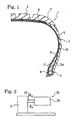
- Fig. 1 is a partial cross-sectional view showing one example of a pneumatic tire manufactured by use of a method of manufacturing a pneumatic tire according to the present invention.
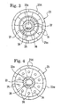
- Fig. 2 is a front view showing a first embodiment of a tire building machine used for the method of manufacturing a pneumatic tire according to the present invention.
- Fig. 3 is an enlarged cross-sectional view taken along line III-III of Fig. 2.
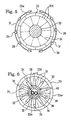
- Fig. 4 is an enlarged cross-sectional view showing a second embodiment of a tire building machine used for the method of manufacturing a pneumatic tire according to the present invention.
- Fig. 5 is an enlarged cross-sectional view showing a third embodiment of a tire building machine used for the method of manufacturing a pneumatic tire according to the present invention.
- Fig. 6 is an enlarged cross-sectional view showing a fourth embodiment of a tire building machine used for the method of manufacturing a pneumatic tire according to the present invention.
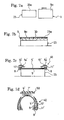
- Fig. 7a is a front view illustrating a step of applying an innerliner having an adhesive on its radially outer surface to a tire building drum that has been heated.
- Fig. 7b is a half cross-sectional view showing a state in which the innerliner is attached to the tire building drum that has been radially expanded.
- Fig. 7c is a schematic view illustrating a step of assembling a carcass assembly.
- Fig. 7d is a schematic view illustrating a step of inflating the carcass assembly to press it against a belt and tread package.
- Embodiments of the present invention will be described in detail below with reference to the attached drawings. Like elements in the drawings are referred by the like reference characters and duplicate descriptions will be omitted.
- Referring to Fig. 1, there is shown one example of a pneumatic tire manufactured by use of a method of manufacturing a pneumatic tire according to the present invention, and reference numeral 1 denotes a pneumatic tire, reference numeral 2 denotes a tread,
reference numeral 3 denotes a sidewall, and reference numeral 4 denotes a bead. - A carcass ply 5 extends between the right and left beads 4 in the tire; the carcass ply comprises a rubber layer and reinforcing cords disposed in the rubber layer; the reinforcing cords, which extend in the radial direction of the tire, are placed at prescribed intervals in the circumferential direction of the tire. A plurality of
belt plies 6 are provided radially outwardly of the carcass play 5 in the tread 2; each belt ply comprises a rubber layer and reinforcing cords disposed in the rubber layer; the reinforcing cords, which obliquely extend in the circumferential direction of the tire, are placed at prescribed intervals in the circumferential direction of the tire. Atread rubber layer 7 are disposed radially outwardly of thebelt plies 6. - A
bead core 8 are embedded in each of the right and left beads 4, and theopposing ends 5a of the carcass ply 5 are turned up around thebead cores 8 from the inner side of the tire toward the outer side thereof. Aninnerliner 9 of thermoplastic elastomer formed into a film is provided inwardly of the carcass ply 5. Aside rubber layer 10 is disposed outwardly of the carcass play 5 in eachsidewall 3.Reference numeral 11 denotes a bead filler placed radially outwardly of eachbead core 6. - Referring to Figs . 2 and 3, there is shown a first embodiment of a tire building machine used for the method of manufacturing a pneumatic tire according to the present invention, and reference numeral 20 denotes a tire building machine.
- This tire building machine 20 includes a
support part 21, a horizontally extendingrotary shaft 22 supported by thesupport part 21, and atire building drum 23 fixed to therotary shaft 22. Therotary shaft 22 is coupled to a driving means (not shown) installed in thesupport part 21. Thetire building drum 23 rotatably supported by thesupport part 21 through therotary shaft 22 is rotated by operation of the driving means. - The
tire building drum 23, which comprises a plurality ofmetal drum segments 23X, is cylindrically formed, as shown in Fig. 3. Thedrum segments 23X are attached expandably and contractibly in the radial direction of the drum to therotary shaft 22 via a conventionally well-known expanding and contracting mechanism schematically shown with chain double-dashed lines. - A heating means 25 that can heat the surface (radially outer surface) 23a of the
tire building drum 23 is provided inside thetire building drum 23. The heating means 25 includes a plurality of ring-shapedelectric heating elements 26. The plurality ofelectric heating elements 26, which are disposed at prescribed intervals in the widthwise direction of the drum and supported bysupport members 27 that protrude on therotary shaft 22, are rotatable with therotary shaft 22. - The
rotary shaft 22 has ahollow interior 22a, in which are placed twowires 28 connected to theelectric heating elements 26. A temperature sensor (not shown) comprising, for example, a thermocouple is attached to eachdrum segment 23X, and the strength of current that flows in eachelectric heating element 26 is adjusted according to the temperature detected by the temperature sensor, whereby the temperature of thesurface 23a of thetire building drum 23 heated can be adjusted. - Referring to Fig. 4, there is shown a second embodiment of a tire building machine used for the method of manufacturing a pneumatic tire according to the present invention. In this second embodiment, the heating means 25 has bar-shaped
electric heating elements 26 instead of the ring-shaped ones described above. The bar-shapedelectric heating elements 26, which extend in the widthwise direction of the drum, are disposed at prescribed intervals in the circumferential direction of the drum. - Referring to Fig. 5, there is shown a third embodiment of a tire building machine used for the method of manufacturing a pneumatic tire according to the present invention. In this third embodiment, the heating means 25 described above comprises an infrared emitter having
light sources 29 such as infrared lamps that emit infrared radiation to thesurface 23a of thetire building drum 23. - The
light sources 29 are attached to a pair of circularlycurved support members 31 at prescribed intervals. The pair of circularlycurved support members 31 are arrange such that they can be moved between an emitting position that are near thesurface 23a shown in the drawing and a waiting position spaced a part from thesurface 23a. Thelight sources 29 are electrically connected to a power supply (not shown), and can be turned on at the emitting position to emit infrared radiation to thesurface 23a of thetire building drum 23, thereby heating thesurface 23a. - When the
infrared emitter 30 is used for the heating means 29 as described above, thesurface 23a of thetire building drum 23 is preferably colored black to effectively heat thesurface 23a of thetire building drum 23 by infrared radiation. All thesurface 23a may be colored black, or only the region of thesurface 23a to which theinnerliner 9 is attached may be colored black. Thesurface 23a of thetire building drum 23 is colored black by, for example, applying a black paint to thesurface 23a. - Referring to Fig. 6, there is shown a fourth embodiment of a tire building machine used for the method of manufacturing a pneumatic tire according to the present invention. In this fourth embodiment, the heating means 25 comprises a medium heating device 33 having a circulating
passage 32, disposed inside thetire building drum 23, for circulating a heating medium that heats thesurface 23a of thetire building drum 23. - A plurality of
first pipes 34 that extend in the widthwise direction of the drum are placed inside thetire building drum 23 at prescribed intervals in the circumferential direction of the drum. There are disposed in the hollow interior 22a of therotary shaft 22 asecond pipe 35 for supply the heating medium to thefirst pipes 34 from a heating medium supply source (not shown), and athird pipe 36 for returning the heating medium from thefirst pipes 34 to the heating medium supply source. Thesecond pipe 35 is coupled to aconnection pipe assembly 38 having a plurality ofbranch pipes 37, which are coupled to the one ends of thefirst pipes 34. - The
third pipe 35 is also coupled to aconnection pipe assembly 40 having a plurality ofbranch pipes 39, which are coupled to the other ends of thefirst pipes 34. The heating medium supplied from the heating medium supply source returns through thesecond pipe 35,connection pipe assembly 38,first pipes 34,connection pipe assembly 40 andthird pipe 36 to the heating medium supply source. The circulatingpassage 32 for circulating the heating medium that heats thesurface 23a of thetire building drum 23 is formed inside thesecond pipe 35,connection pipe assembly 38,first pipes 34,connection pipe assembly 40 andthird pipe 36. - The circulating
passage 32 is preferably arranged so as to pass near thesurface 23a of thetire building drum 23 to heat thesurface 23a quickly, but may be arranged only in the hollow interior 22a of therotary shaft 22. - The heating medium may be any heating medium that can heat the
surface 23a of thetire building drum 23, and examples of the heating medium preferably includes hot water, heated oil and the like. - The method of manufacturing a pneumatic tire of the present invention will be described below with reference to Figs. 7a to 7d.
- First, the heating means 25 is turned on to heat the
surface 23a of thetire building drum 23 in advance. The heat-up temperature of thesurface 23a is ranged from 40 to 60.degree. C. when an adhesive having a low tackiness at a room temperature, described later, is used. The heating means 25 heats the surface at least until an uncured carcass ply 5', described later, is applied. - Next, as shown in Fig. 7a, a
cylindrical innerliner film 9 of thermoplastic elastomer having an adhesive on its radiallyouter surface 9a is placed radially outwardly of thetire building drum 23. The adhesive used here is one having a glass transition temperature in the range of -20 to 30.degree. C. - The glass transition temperature ranged from -20 to 30.degree. C. is high in cohesion and is low in tackiness at a room temperature, so handling of the innerliner with the adhesive is facilitated. When the surface is heated at a temperature of 40 to 60.degree. C., the adhesive exhibits a sufficient tackiness, facilitating adhering of an uncured carcass ply 5'.
- If the glass transition temperature is lower than -20.degree. C., handling is deteriorated because the tackiness of the adhesive is too high at a room temperature. If the glass transition temperature is higher than 30.degree. C., the surface needs to be heated up to temperatures above 60.degree. C. to obtain a sufficient tackiness; therefore, it is not preferable in productivity because of an increase in heating time.
- After placing of the
innerliner 9, thetire building drum 23 is radially expanded to attach thecylindrical innerliner 9 to thesurface 23a of thetire building drum 23, as shown in Fig. 7b. In Fig. 7b,reference numeral 30 denotes a layer of the adhesive that has been applied to the radiallyouter surface 9a of theinnerliner 9. - By attaching the
innerliner 9, theadhesive layer 30 is heated to thereby exhibit a sufficient tackiness. After the adhesive layer exhibits a sufficient tackiness, uncured tire components are attached to assemble a green tire as in the prior art. That is, an uncured sheet-shaped carcass ply 5' is bonded onto the radially outer side of theinnerliner 9 with theadhesive layer 30, and the circumferential opposing ends of the uncured carcass ply 5' are spliced together.Bead cores 8 to which uncured bead fillers 11' are attached in advance are then placed on the radially outer side of the uncured carcass ply 5'. The opposing ends 5a' of the uncured carcass ply 5' are turned up so as to wrap thebead cores 8 and the uncured bead fillers 11', and uncured side rubber layers 10' are applied radially outwardly thereof to form a carcass assembly 40 (see Fig. 7c). - The
tire building drum 23 is radially contracted, and thecarcass assembly 40 that has been cylindrically formed is removed from thetire building drum 23. After thecarcass assembly 40 has been removed from thetire building drum 23, the heatedadhesive layer 30 is naturally cooled, whereby the temperature thereof is lowered, which makes the cohesion of theadhesive layer 30 high again. Therefore, theinnerliner 9 does not easily separate from the uncured carcass ply 5'. The heatedadhesive layer 30 is naturally cooled down to a room temperature during assembling of the green tire, so it is not necessary to provide a cooling step in particular. However, a forcibly cooling step may be provided to shorten the assembling time. - Next, the
carcass assembly 40 that has been removed from thetire building drum 23 is inflated into a toroidal shape, as shown in Fig. 7d, and pressed against the radially inner side of a cylindrical belt and treadpackage 50, comprising uncured belt plies 6' and an uncured tread rubber layer 7', that has been formed in advance. The belt and treadpackage 50 is adhered to thecarcass assembly 40 by pressing with press rollers (not shown) to form the green tire. The green tire is cured by heating, obtaining the pneumatic tire 1 shown in Fig. 1. - According to the present invention, since the
surface 23a of thetire building drum 23 is preheated, an adhesive that is high in cohesion and low in tackiness at a room temperature, and is high in tackiness when heated, can be used for the adhesive that is applied to the radiallyouter surface 9a of theinnerliner 9. - Therefore, when the
innerliner 9 of thermoplastic elastomer formed into a film is applied to thetire building drum 23, even though parts of the radiallyouter surface 9a of theinnerliner 9 to which the adhesive has been applied are stuck to each other, the parts can be easily separated from each other, allowing for easy handling of theinnerliner 9. Theinnerliner 9 and uncured carcass ply 5' can be adhered to each other with theadhesive layer 30 being high in tackiness, and the heatedadhesive layer 30 is naturally cooled during assembling of the green tire, becoming high in cohesion again. Accordingly, theinnerliner 9 of the assembled green tire can be suppressed from separating from the uncured carcass ply 5'. - In the present invention, the thickness of the
innerliner 9 is preferably in the range from 80 µm to 300µm. The thickness is less than 80 µm, the innerliner can not provide a sufficient function as a layer that prevents air permeation. If the thickness is greater than 300µm, it takes time to heat the adhesive, deteriorating productivity. - The thermoplastic elastomer of which the
innerliner 9 is formed may be a well-known one conventionally used for theinnerliner 9, and preferably include a thermoplastic elastomer having a thermoplastic resin component and rubber component parts dispersed therein, such as thermoplastic elastomer composition disclosed in Unexamined Japanese Patent Application Publication No. 11-199713, for example. - The adhesive that is applied to the radially outer surface of the
innerliner 9 may be a conventionally well-known one, and preferred examples of the adhesive may include an adhesive of styrene block copolymer, and the like. - In the method of manufacturing a pneumatic tire of the present invention, it is preferable in terms of productivity that the
surface 23a of thetire building drum 23 is preheated before thecylindrical innerliner 9 having the adhesive on its radially outer surface is placed, as described above. However, after theinnerliner 9 having the adhesive on its radially outer surface is attached to thetire building drum 23, thesurface 23a of thetire building drum 23 may be heated by the heating means 25 to heat the adhesive. - Prepared were test films 1 to 5 including innerliner films of thermoplastic elastomer and adhesives A to E applied to the respective outer surfaces thereof, the adhesives A to E having blending ratios and glass transition temperatures shown in Table 1. Handling ability of the test films were evaluated on the grade of four scales that are ⊚, ○, Δ, and ×.
- ⊚ means that parts of the outer surface of the test film to which the adhesive had been applied were hardly stuck to each other even though the parts were forced to contact to each other. ○ means that, when parts of the outer surface of the test film to which the adhesive had been applied were forced to contact to each other, the parts were stuck to each other, but they could be easily separated from each other. Δ means that, when parts of the outer surface of the test film to which the adhesive had been applied were forced to contact to each other, the parts were stuck to each other, but they could be separated from each other when they were separated soon after sticking. × means that, when parts of the outer surface of the test film to which the adhesive had been applied were forced to contact to each other, the parts were stuck to each other, and when an attempt was made to separate the parts, the test film was elongated with the parts not separated. ⊚, ○ and Δ belong to allowable levels. The results were shown in Table 2.
- Test green tires 1 to 5 each having a construction shown in Fig. 1 were prepared according to the method of the present invention described above, using the adhesives A to E. The temperature of the surface of the tire building drum was about 50.degree. C. Each test green tire was checked for separation resistance of the innerliner according to the following method, obtaining the results shown in Table 3.
- The test green tire is cut to visually observe the state of separation between the innerliner and uncured carcass ply, evaluating the result on the grade of four scales that are ⊚, ○, Δ, and ×.
- ⊚ means that there was no separation. ○ means that there was very little separation that was not problematic occurred in the connection part of the uncured carcass ply. Δ means that there was separation occurred in the connection part of the uncured carcass ply and another part other than the connection part, but the separation parts could be repaired by press operation. × means that there was separation occurred around the entire circumference of the tire, and repair of the separation was impossible. ⊚ and ○ belong to allowable levels.
Table 1 Compounding Ingredients Name of Articles Company Name A B C D B SBS Tufprene A Asahikasei Co., Ltd. 40 40 40 40 40 ESBS Epofriend A1020 Daicel Chemical Industries, Ltd. 60 60 60 60 60 Stearic Acid Granular Stearic Acid Nihonyushi Co., Ltd. 1 1 1 1 1 Dicumyl Peroxide Percumyl D-40 Kayaku Akuzo Co., Ltd. 1 1 1 1 1 Terpene Resin YS Resin D105 Yasuhara Chemical Co., Ltd. 30 50 70 Modified Terpene Resin YS Resin TR105 Yasuhara Chemical Co., Ltd. 100 130 Glass Transition Temperature (°C) -30 -20 10 30 40 Note: (1) SBS is short for styrene-butadiene block copolymer. (2) ESBS is short for epoxidized styrene-butadiene block copolymer. (3) The values of the compounding ingredients are shown in parts by weight. Table 2 Test Film 1 Test Film 2 Test Film 3Test Film 4 Test Film 5 Adhesive A B C D E Handling Ability × Δ ○ ⊚ ⊚ Table 3 Test Green Tire 1 Test Green Tire 2 Test Green Tire 3Test Green Tire 4 Test Green Tire 5 Adhesive A B C D B Separation Resistance Δ ⊚ ⊚ ○ Δ - From Tables 1 to 3, it is understood that the glass transition temperature of the adhesive is preferably ranged from -20 to 30.degree. C.
- The present invention having the aforementioned excellent effects can be very effectively used for manufacturing pneumatic tires to be mounted on vehicles.
Claims (11)
- A method of manufacturing a pneumatic tire having an innerliner formed of thermoplastic elastomer, comprising the steps of:heating a surface of a tire building drum in advance;placing the innerliner on the heated surface of the tire building drum, the innerliner being cylindrically shaped and having a radially outer surface to which an adhesive has been applied;disposing uncured tire components radially outwardly of the innerliner to form a green tire; andcuring the green tire.
- A method of manufacturing a pneumatic tire according to claim 1, wherein the step of disposing uncured tire components includes disposing an uncured carcass ply, bead cores and uncured side rubber layers radially outwardly of the innerliner to form a carcass assembly and inflating the carcass assembly in a toroidal shape to press against a radially inner side of a cylindrical belt and tread package having an uncured belt ply and an uncured tread rubber layer.
- A method of manufacturing a pneumatic tire according to claim 1 or 2, wherein the adhesive has a glass transition temperature ranged from -20.degree. C. to 30.degree. C.
- A method of manufacturing a pneumatic tire according to claim 3, wherein the surface of the tire building drum is heated at a temperature of 40.degree. C. to 60.degree. C. in the step of heating the tire building drum.
- A method of manufacturing a pneumatic tire according to any one of claims 1 or 4, wherein the innerliner is 80 µm to 300 µm in thickness.
- A tire building machine comprising a tire building drum that is expandable and contractible, and heating means that can heat a surface of the tire building drum.
- A tire building machine according to claim 6, wherein the heating means includes an electric heating element, which is disposed inside the tire building drum.
- A tire building machine according to claim 6, wherein the heating means comprises an infrared emitter having light sources for emitting infrared radiation to the surface of the tire building drum.
- A tire building machine according to claim 8, wherein the surface of the tire building drum is black in color.
- A tire building machine according to claim 6, wherein the heating means comprises a medium heating device having a circulating passage for circulating a heating medium that heats the surface of the tire building drum, the circulating passage being provided inside the tire building drum.
- A tire building machine according to any one of claims 6 to 10, wherein the tire building drum comprises a plurality of drum segments formed of metal.
Applications Claiming Priority (3)
| Application Number | Priority Date | Filing Date | Title |
|---|---|---|---|
| JP2003275296 | 2003-07-16 | ||
| JP2003275293 | 2003-07-16 | ||
| PCT/JP2004/010098 WO2005007392A1 (en) | 2003-07-16 | 2004-07-15 | Pneumatic tire producing method and tire forming drum used for the method |
Publications (3)
| Publication Number | Publication Date |
|---|---|
| EP1645404A1 true EP1645404A1 (en) | 2006-04-12 |
| EP1645404A4 EP1645404A4 (en) | 2007-10-03 |
| EP1645404B1 EP1645404B1 (en) | 2013-08-21 |
Family
ID=34082354
Family Applications (1)
| Application Number | Title | Priority Date | Filing Date |
|---|---|---|---|
| EP04747564.5A Expired - Fee Related EP1645404B1 (en) | 2003-07-16 | 2004-07-15 | Pneumatic tire producing method and tire forming drum |
Country Status (5)
| Country | Link |
|---|---|
| US (1) | US7704343B2 (en) |
| EP (1) | EP1645404B1 (en) |
| JP (1) | JP3799363B2 (en) |
| CN (1) | CN1822947B (en) |
| WO (1) | WO2005007392A1 (en) |
Cited By (3)
| Publication number | Priority date | Publication date | Assignee | Title |
|---|---|---|---|---|
| WO2008129363A1 (en) | 2007-04-23 | 2008-10-30 | Pirelli Tyre S.P.A. | Process and apparatus for manufacturing pneumatic tyres |
| EP2025499A1 (en) * | 2006-05-26 | 2009-02-18 | The Yokohama Rubber Co., Ltd. | Method of producing pneumatic tire |
| FR2927567A1 (en) * | 2008-08-01 | 2009-08-21 | Michelin Soc Tech | Air-tight internal coating layer manufacturing method for tubeless tire of automobile, involves wrapping tread around support, where tread length is sufficient such that external end of tread is integrated at tread part than at external end |
Families Citing this family (12)
| Publication number | Priority date | Publication date | Assignee | Title |
|---|---|---|---|---|
| CA2517822C (en) * | 2004-09-06 | 2009-10-27 | Honda Motor Co., Ltd. | Seat mount structure for saddle ride vehicle |
| JP4893321B2 (en) * | 2007-01-12 | 2012-03-07 | 横浜ゴム株式会社 | Pneumatic tire manufacturing method |
| JP4297290B2 (en) * | 2007-12-21 | 2009-07-15 | 横浜ゴム株式会社 | Pneumatic tire manufacturing method |
| JP4410820B2 (en) * | 2007-12-27 | 2010-02-03 | 住友ゴム工業株式会社 | Pneumatic tire manufacturing method and green tire molding apparatus |
| US8776851B2 (en) | 2008-08-29 | 2014-07-15 | The Goodyear Tire & Rubber Company | Film to keep tire surface clean and simultaneously prime for better adhesion of balance pad |
| JP2010137820A (en) * | 2008-12-15 | 2010-06-24 | Yokohama Rubber Co Ltd:The | Pneumatic tire and method of manufacturing the same |
| JP5353254B2 (en) * | 2009-01-13 | 2013-11-27 | 横浜ゴム株式会社 | Manufacturing method of unvulcanized tire |
| US8454778B2 (en) | 2010-11-15 | 2013-06-04 | Ramendra Nath Majumdar | Pneumatic tire with barrier layer and method of making the same |
| JP5068875B1 (en) * | 2011-05-13 | 2012-11-07 | 住友ゴム工業株式会社 | Pneumatic tire manufacturing method |
| JP5299539B1 (en) * | 2012-04-09 | 2013-09-25 | 横浜ゴム株式会社 | Pneumatic tire |
| JP6433971B2 (en) | 2013-03-13 | 2018-12-05 | ビーエーエスエフ ソシエタス・ヨーロピアBasf Se | Inner liner for pneumatic tire assembly |
| JP7355636B2 (en) * | 2019-12-13 | 2023-10-03 | Toyo Tire株式会社 | Green tire molding equipment |
Citations (4)
| Publication number | Priority date | Publication date | Assignee | Title |
|---|---|---|---|---|
| GB807463A (en) * | 1955-02-08 | 1959-01-14 | Goodyear Tire & Rubber | Method and apparatus for making diaphragms for use with tyres |
| LU60972A1 (en) * | 1969-05-31 | 1970-08-04 | ||
| JPH11320567A (en) * | 1998-05-11 | 1999-11-24 | Bridgestone Corp | Apparatus and method for vulcanizing tire |
| EP1295703A2 (en) * | 2001-09-21 | 2003-03-26 | The Goodyear Tire & Rubber Company | Expandable tire building drum |
Family Cites Families (13)
| Publication number | Priority date | Publication date | Assignee | Title |
|---|---|---|---|---|
| JPS57208233A (en) * | 1981-06-18 | 1982-12-21 | Mitsubishi Heavy Ind Ltd | Method and apparatus for manufacturing radial tire |
| JPH06234172A (en) * | 1993-02-10 | 1994-08-23 | Bridgestone Corp | Forming method of green tire and manufacture of pneumatic tire |
| JP3159886B2 (en) | 1995-03-24 | 2001-04-23 | 横浜ゴム株式会社 | Pneumatic tire and manufacturing method thereof |
| KR100413882B1 (en) * | 1995-05-02 | 2004-04-28 | 요코하마 고무 가부시키가이샤 | Manufacturing method of air tire |
| JPH1025375A (en) | 1996-07-12 | 1998-01-27 | Yokohama Rubber Co Ltd:The | Thermoplastic elastomer composition and pneumatic tire and hose using the same |
| DE19630452C1 (en) * | 1996-07-27 | 1997-07-03 | Continental Ag | Tyre carcass building manufacture having more extensible shrunk cords at overlapping point |
| JP3236257B2 (en) | 1998-01-13 | 2001-12-10 | 横浜ゴム株式会社 | Thermoplastic elastomer composition and pneumatic tire using the same |
| US6332999B1 (en) * | 1998-07-31 | 2001-12-25 | Pirelli Pneumatici S.P.A. | Method and apparatus for moulding and curing tires for vehicle wheels |
| US6409959B1 (en) * | 1998-07-31 | 2002-06-25 | Pirelli Pneumatici S.P.A. | Process for manufacturing, moulding and curing tires for vehicle wheels |
| ATE267691T1 (en) * | 1999-08-10 | 2004-06-15 | Sedepro | STIFF CORE IN TWO PARTS FOR PRODUCING AIR TIRES |
| JP4496614B2 (en) | 2000-07-18 | 2010-07-07 | 横浜ゴム株式会社 | Inflation molding method for tires using hot air or hot gas |
| JP2004106398A (en) | 2002-09-19 | 2004-04-08 | Sumitomo Rubber Ind Ltd | Method for manufacturing tire |
| US8114335B2 (en) * | 2002-12-30 | 2012-02-14 | The Goodyear Tire & Rubber Company | Partial depth-wise cure of a tire inner liner |
-
2004
- 2004-07-15 JP JP2005511839A patent/JP3799363B2/en not_active Expired - Fee Related
- 2004-07-15 CN CN200480020058.7A patent/CN1822947B/en not_active Expired - Fee Related
- 2004-07-15 US US10/560,838 patent/US7704343B2/en not_active Expired - Fee Related
- 2004-07-15 WO PCT/JP2004/010098 patent/WO2005007392A1/en active Application Filing
- 2004-07-15 EP EP04747564.5A patent/EP1645404B1/en not_active Expired - Fee Related
Patent Citations (4)
| Publication number | Priority date | Publication date | Assignee | Title |
|---|---|---|---|---|
| GB807463A (en) * | 1955-02-08 | 1959-01-14 | Goodyear Tire & Rubber | Method and apparatus for making diaphragms for use with tyres |
| LU60972A1 (en) * | 1969-05-31 | 1970-08-04 | ||
| JPH11320567A (en) * | 1998-05-11 | 1999-11-24 | Bridgestone Corp | Apparatus and method for vulcanizing tire |
| EP1295703A2 (en) * | 2001-09-21 | 2003-03-26 | The Goodyear Tire & Rubber Company | Expandable tire building drum |
Non-Patent Citations (1)
| Title |
|---|
| See also references of WO2005007392A1 * |
Cited By (5)
| Publication number | Priority date | Publication date | Assignee | Title |
|---|---|---|---|---|
| EP2025499A1 (en) * | 2006-05-26 | 2009-02-18 | The Yokohama Rubber Co., Ltd. | Method of producing pneumatic tire |
| EP2025499A4 (en) * | 2006-05-26 | 2010-08-04 | Yokohama Rubber Co Ltd | Method of producing pneumatic tire |
| WO2008129363A1 (en) | 2007-04-23 | 2008-10-30 | Pirelli Tyre S.P.A. | Process and apparatus for manufacturing pneumatic tyres |
| US8603275B2 (en) | 2007-04-23 | 2013-12-10 | Pirelli Tyre S.P.A. | Process and apparatus for manufacturing pneumatic tyres |
| FR2927567A1 (en) * | 2008-08-01 | 2009-08-21 | Michelin Soc Tech | Air-tight internal coating layer manufacturing method for tubeless tire of automobile, involves wrapping tread around support, where tread length is sufficient such that external end of tread is integrated at tread part than at external end |
Also Published As
| Publication number | Publication date |
|---|---|
| US20070095458A1 (en) | 2007-05-03 |
| EP1645404B1 (en) | 2013-08-21 |
| JPWO2005007392A1 (en) | 2006-08-31 |
| JP3799363B2 (en) | 2006-07-19 |
| CN1822947B (en) | 2010-12-22 |
| US7704343B2 (en) | 2010-04-27 |
| CN1822947A (en) | 2006-08-23 |
| EP1645404A4 (en) | 2007-10-03 |
| WO2005007392A1 (en) | 2005-01-27 |
Similar Documents
| Publication | Publication Date | Title |
|---|---|---|
| EP1645404B1 (en) | Pneumatic tire producing method and tire forming drum | |
| EP2397347B1 (en) | Method for making pneumatic tire with foam noise damper and tire with foam noise damper | |
| JP5680266B2 (en) | Pneumatic tire and retreaded tire manufacturing method | |
| EP2457720B1 (en) | Method for making pneumatic tire with foam noise damper | |
| KR101515669B1 (en) | Process for producing pneumatic tire | |
| EP2000292B1 (en) | Method for producing pneumatic tire | |
| CN102310574A (en) | Method for making pneumatic tire with foam noise damper | |
| JP2012000989A (en) | Method for making pneumatic tire with foam noise damper | |
| US20090229737A1 (en) | Method for repairing inner face portion of pneumatic tire and repair member for inner face portion | |
| JP4407773B1 (en) | Pneumatic tire manufacturing method | |
| KR101286519B1 (en) | Method of manufacturing pneumatic tire | |
| CN101151144A (en) | Method of repairing inside surface portion of pneumatic tire, and relevant inside surface portion repair material | |
| JP4853577B2 (en) | Pneumatic tire manufacturing method | |
| US20220024166A1 (en) | Methods for retreading tires employing cushion gum with stable dinitrile oxide cure system | |
| JP2004188610A (en) | Method for manufacturing recapped tire | |
| JP4308988B2 (en) | Pneumatic tire manufacturing method | |
| JP2001269945A (en) | Tire and manufacturing method therefor | |
| JP6024697B2 (en) | Pneumatic tire manufacturing method | |
| JP2005178038A (en) | Manufacturing method of retreaded tire and precured tread body |
Legal Events
| Date | Code | Title | Description |
|---|---|---|---|
| PUAI | Public reference made under article 153(3) epc to a published international application that has entered the european phase |
Free format text: ORIGINAL CODE: 0009012 |
|
| 17P | Request for examination filed |
Effective date: 20060110 |
|
| AK | Designated contracting states |
Kind code of ref document: A1 Designated state(s): DE FR |
|
| DAX | Request for extension of the european patent (deleted) | ||
| RBV | Designated contracting states (corrected) |
Designated state(s): DE FR |
|
| A4 | Supplementary search report drawn up and despatched |
Effective date: 20070904 |
|
| RIC1 | Information provided on ipc code assigned before grant |
Ipc: B29D 30/26 20060101ALI20070829BHEP Ipc: B29D 30/00 20060101AFI20070829BHEP Ipc: B29D 30/30 20060101ALI20070829BHEP |
|
| 17Q | First examination report despatched |
Effective date: 20110801 |
|
| GRAP | Despatch of communication of intention to grant a patent |
Free format text: ORIGINAL CODE: EPIDOSNIGR1 |
|
| GRAS | Grant fee paid |
Free format text: ORIGINAL CODE: EPIDOSNIGR3 |
|
| RIN1 | Information on inventor provided before grant (corrected) |
Inventor name: KANENARI, DAISUKE C/O THE YOKOHAMA RUBBER CO. LTD. |
|
| GRAA | (expected) grant |
Free format text: ORIGINAL CODE: 0009210 |
|
| AK | Designated contracting states |
Kind code of ref document: B1 Designated state(s): DE FR |
|
| REG | Reference to a national code |
Ref country code: DE Ref legal event code: R096 Ref document number: 602004043110 Country of ref document: DE Effective date: 20131017 |
|
| PLBE | No opposition filed within time limit |
Free format text: ORIGINAL CODE: 0009261 |
|
| STAA | Information on the status of an ep patent application or granted ep patent |
Free format text: STATUS: NO OPPOSITION FILED WITHIN TIME LIMIT |
|
| 26N | No opposition filed |
Effective date: 20140522 |
|
| REG | Reference to a national code |
Ref country code: DE Ref legal event code: R097 Ref document number: 602004043110 Country of ref document: DE Effective date: 20140522 |
|
| REG | Reference to a national code |
Ref country code: FR Ref legal event code: PLFP Year of fee payment: 12 |
|
| PGFP | Annual fee paid to national office [announced via postgrant information from national office to epo] |
Ref country code: DE Payment date: 20150707 Year of fee payment: 12 |
|
| PGFP | Annual fee paid to national office [announced via postgrant information from national office to epo] |
Ref country code: FR Payment date: 20150629 Year of fee payment: 12 |
|
| REG | Reference to a national code |
Ref country code: DE Ref legal event code: R119 Ref document number: 602004043110 Country of ref document: DE |
|
| PG25 | Lapsed in a contracting state [announced via postgrant information from national office to epo] |
Ref country code: FR Free format text: LAPSE BECAUSE OF NON-PAYMENT OF DUE FEES Effective date: 20160801 Ref country code: DE Free format text: LAPSE BECAUSE OF NON-PAYMENT OF DUE FEES Effective date: 20170201 |
|
| REG | Reference to a national code |
Ref country code: FR Ref legal event code: ST Effective date: 20170331 |