EP1645229A1 - Bänderkraft-Erfassungssystem - Google Patents
Bänderkraft-Erfassungssystem Download PDFInfo
- Publication number
- EP1645229A1 EP1645229A1 EP04024165A EP04024165A EP1645229A1 EP 1645229 A1 EP1645229 A1 EP 1645229A1 EP 04024165 A EP04024165 A EP 04024165A EP 04024165 A EP04024165 A EP 04024165A EP 1645229 A1 EP1645229 A1 EP 1645229A1
- Authority
- EP
- European Patent Office
- Prior art keywords
- insert
- spring
- ligament
- structures
- force
- Prior art date
- Legal status (The legal status is an assumption and is not a legal conclusion. Google has not performed a legal analysis and makes no representation as to the accuracy of the status listed.)
- Granted
Links
Images

Classifications
-
- A—HUMAN NECESSITIES
- A61—MEDICAL OR VETERINARY SCIENCE; HYGIENE
- A61B—DIAGNOSIS; SURGERY; IDENTIFICATION
- A61B5/00—Measuring for diagnostic purposes; Identification of persons
- A61B5/103—Measuring devices for testing the shape, pattern, colour, size or movement of the body or parts thereof, for diagnostic purposes
-
- A—HUMAN NECESSITIES
- A61—MEDICAL OR VETERINARY SCIENCE; HYGIENE
- A61B—DIAGNOSIS; SURGERY; IDENTIFICATION
- A61B17/00—Surgical instruments, devices or methods
- A61B17/02—Surgical instruments, devices or methods for holding wounds open, e.g. retractors; Tractors
- A61B17/025—Joint distractors
-
- A—HUMAN NECESSITIES
- A61—MEDICAL OR VETERINARY SCIENCE; HYGIENE
- A61B—DIAGNOSIS; SURGERY; IDENTIFICATION
- A61B5/00—Measuring for diagnostic purposes; Identification of persons
- A61B5/06—Devices, other than using radiation, for detecting or locating foreign bodies ; Determining position of diagnostic devices within or on the body of the patient
- A61B5/061—Determining position of a probe within the body employing means separate from the probe, e.g. sensing internal probe position employing impedance electrodes on the surface of the body
- A61B5/064—Determining position of a probe within the body employing means separate from the probe, e.g. sensing internal probe position employing impedance electrodes on the surface of the body using markers
-
- A—HUMAN NECESSITIES
- A61—MEDICAL OR VETERINARY SCIENCE; HYGIENE
- A61B—DIAGNOSIS; SURGERY; IDENTIFICATION
- A61B5/00—Measuring for diagnostic purposes; Identification of persons
- A61B5/45—For evaluating or diagnosing the musculoskeletal system or teeth
- A61B5/4533—Ligaments
-
- A—HUMAN NECESSITIES
- A61—MEDICAL OR VETERINARY SCIENCE; HYGIENE
- A61B—DIAGNOSIS; SURGERY; IDENTIFICATION
- A61B90/00—Instruments, implements or accessories specially adapted for surgery or diagnosis and not covered by any of the groups A61B1/00 - A61B50/00, e.g. for luxation treatment or for protecting wound edges
- A61B90/06—Measuring instruments not otherwise provided for
-
- A—HUMAN NECESSITIES
- A61—MEDICAL OR VETERINARY SCIENCE; HYGIENE
- A61B—DIAGNOSIS; SURGERY; IDENTIFICATION
- A61B17/00—Surgical instruments, devices or methods
- A61B17/02—Surgical instruments, devices or methods for holding wounds open, e.g. retractors; Tractors
- A61B17/025—Joint distractors
- A61B2017/0268—Joint distractors for the knee
-
- A—HUMAN NECESSITIES
- A61—MEDICAL OR VETERINARY SCIENCE; HYGIENE
- A61B—DIAGNOSIS; SURGERY; IDENTIFICATION
- A61B90/00—Instruments, implements or accessories specially adapted for surgery or diagnosis and not covered by any of the groups A61B1/00 - A61B50/00, e.g. for luxation treatment or for protecting wound edges
- A61B90/06—Measuring instruments not otherwise provided for
- A61B2090/061—Measuring instruments not otherwise provided for for measuring dimensions, e.g. length
-
- A—HUMAN NECESSITIES
- A61—MEDICAL OR VETERINARY SCIENCE; HYGIENE
- A61B—DIAGNOSIS; SURGERY; IDENTIFICATION
- A61B90/00—Instruments, implements or accessories specially adapted for surgery or diagnosis and not covered by any of the groups A61B1/00 - A61B50/00, e.g. for luxation treatment or for protecting wound edges
- A61B90/06—Measuring instruments not otherwise provided for
- A61B2090/064—Measuring instruments not otherwise provided for for measuring force, pressure or mechanical tension
-
- A—HUMAN NECESSITIES
- A61—MEDICAL OR VETERINARY SCIENCE; HYGIENE
- A61B—DIAGNOSIS; SURGERY; IDENTIFICATION
- A61B90/00—Instruments, implements or accessories specially adapted for surgery or diagnosis and not covered by any of the groups A61B1/00 - A61B50/00, e.g. for luxation treatment or for protecting wound edges
- A61B90/36—Image-producing devices or illumination devices not otherwise provided for
- A61B2090/363—Use of fiducial points
-
- A—HUMAN NECESSITIES
- A61—MEDICAL OR VETERINARY SCIENCE; HYGIENE
- A61B—DIAGNOSIS; SURGERY; IDENTIFICATION
- A61B5/00—Measuring for diagnostic purposes; Identification of persons
- A61B5/68—Arrangements of detecting, measuring or recording means, e.g. sensors, in relation to patient
- A61B5/6846—Arrangements of detecting, measuring or recording means, e.g. sensors, in relation to patient specially adapted to be brought in contact with an internal body part, i.e. invasive
- A61B5/6867—Arrangements of detecting, measuring or recording means, e.g. sensors, in relation to patient specially adapted to be brought in contact with an internal body part, i.e. invasive specially adapted to be attached or implanted in a specific body part
- A61B5/6878—Bone
Definitions
- the invention relates to a ligament force detection system.
- Such systems are used in the medical field to keep body structures, mostly bone structures on tension apart and set the forces occurring at the tapes. The corresponding forces should be adjusted if z.
- Band structures are manipulated to restore the anatomical position of the leg axis. This is especially true for cases where joint prostheses are used.
- the handling of the system and the communication of the force or voltage measurement data should be improved.
- a ligament force detection system has an insert which can be introduced between two body structures connected to one another by means of ligaments. Furthermore, it has a measuring arrangement which determines the forces acting on the bands, and to that extent the system according to the invention generally still corresponds to those known from the prior art.
- the ligament-force detection system according to the invention is characterized in that the insert has a predetermined elasticity (in the case of a spring whose spring constant) are arranged on the body structures reference arrangements, and that the measuring arrangement comprises a medical navigation system, which displacements of the body structures - on the Reference structures detected so that from the shifts and the known elasticity can be concluded on the forces acting on the bands.
- the force is no longer continuously measured directly between the body structures (bone ends) to then further communicate the force value, but an elasticity or spring constant is defined by the predetermined elasticity of the insert, and the force itself can then be determined simply by measuring the resulting displacements or paths.
- such routes can be determined "from outside” by simple measuring processes (eg with the aid of medical navigation systems), so that it is no longer necessary to communicate force values "from the inside", namely directly from the insert by wire or line to where they are processed or used.
- the invention provides a way to determine the force or tension data ligamentary structures in a wireless manner and without the use of transducers and sensors, intraoperatively.
- the insert can therefore be configured as a simple mechanical component and can be sterilize easily. Energy supplies in use or for use are no longer necessary.
- the insert may comprise a spring having a known spring constant.
- the length of the spring is advantageously variable by an adjusting mechanism in order to determine the biasing force of the spring in a starting position.
- the insert may be constructed to include an outer body in which the spring is mounted and at least one pair of spreader extensions, in particular a pair of spreader plates, biased by the springs and which is insertable between the body structures.
- the two outer bodies are adjustably connected to each other at a distance, and especially if the two Sp Schwarzfortsatzschreibe may extend substantially parallel and substantially in the same direction.
- the latter feature can be realized for example by an articulated arrangement of the Sp Schwarzfortsatzcrue.
- one pair of spinal extensions is designed in one particular shape (eg, longer than the other)
- the insert may be used in knee applications and perform its function even when the patella remains in its anatomical position. This particular form of a pair of spinal processes is a prerequisite for the unobstructed movement of the patella.
- a preferred embodiment of the system according to the invention is that the navigation system calculates the forces acting on the bands from the displacements and the elasticity and outputs this information in real time.
- ligament balancing Device shows an insert of a ligament force detection system according to the invention is provided with the reference numeral 1 and shown in a sectional view. This use is as already mentioned above, hereinafter also referred to as ligament balancing device (Ligament Balancing Device).
- the device 1 has an outer body or an outer sleeve 3, which surrounds the mechanism located therein.
- an upper inner sleeve 4 is guided, as well as a lower inner sleeve 5.
- a spring 7 is inserted, and this is numbered in the right part of the device 1, which is essentially the same - the left part.
- a bottom part 6 is provided, which is screwed to the outer sleeve 3.
- This bottom part 6 secures a Rädelschraube 8, which can adjust the spring 7 in length by rotation via a helical gear by the inner sleeve 5 is raised and guided in the outer sleeve 3.
- About the upper inner sleeve 4 each have a pair of spreader plates 2 are arranged on the right and left portion of the device 1, two medial and lateral spreader plates. The upper of the spreader plates shown are each fixed to the upper inner sleeve 4, the lower of the outer sleeve. 3
- the spreader plates 2 are pressed apart by the force of the spring 7.
- a hinge assembly 9 Between the left and the right part of the device 1 is a hinge assembly 9. With this joint arrangement, these two parts can be articulated to each other, whereby the total spacing of the spreader plates can be adjusted. As the perspective and sectional view of Figure 2 is removed, one of the Sp Dr Stirnclame a different shape than the other. With the help of the hinge mechanism 9, the entire device 1 can then be adjusted so that the two parts are close to each other and the spreader plates protrude substantially in the same direction. Because one of the spreader plate pairs has a particular shape (length, angulation), it can then engage in a more distant space, and the device 1 as a whole can be positioned, for example in knee applications, so as not to interfere with the patella in its anatomical path.
- FIG. 3 represents only a part of the device 1, and it indicates the spring travel X, to which reference will be made later.
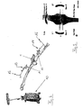
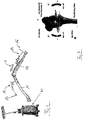
- FIGS. 4 and 6 ligament force detection systems according to the invention are shown in their entirety.
- the same reference numerals designate the same parts, the only difference is that the state of FIG. 4 shows a non-angled and the state of FIG. 6 shows an angled joint position.
- a navigation system 10 is shown on the left, which consists of a camera system, a computer unit and associated software.
- the navigation system 10 can perform position locating and provides data on spatial coordinates of reference structures, which it captures with the camera system and with the help of these data the image-guided surgery allows.
- Reference structures which can be detected by the navigation system 10 are, for example, reference structures 13 and 14, each of which has characteristically arranged marker arrangements 15 and 16.
- the reference structures 13 and 14 are fixed to the bones 11 and 12, here femur 11 and lower leg bones 12. Between the articular processes of the bones 11 and 12, the ligament balancing device 1 is used with the spreader plates, as described above.
- the ligament balancer 1 (balancing aid) is inserted into the joint space.
- the patella may remain at its anatomical position because of the previously discussed particular shape of one of the spreader plate pairs.
- the medial and the lateral band will exert a counterforce.
- the spring 7 (Figure 1) is compressed to a certain length.
- the medial (inside) and lateral (outside) can be spread with the same force on which the mechanical axes of the bones align themselves. From the difference between the unloaded spring length X ( Figure 3) and the compressed spring length and from the spring constant can calculate the existing force, ie the force on the medial and lateral band.
- the Force can be read on a scale on the device 1 itself, for example.
- the invention makes it possible to continuously determine the ligament forces even during the further operation, for example when a band detachment takes place in succession to correct the position of thigh and lower leg relative to one another.
- the size of the joint space can be determined with the aid of the navigation system 10, which constantly determines the position of the femur 11 and tibia 12 via the reference structures 13 and 14 and the thereto attached marker groups 15 and 16 monitored.
- the navigation system 10 can calculate the forces and stresses of the bands, even at different angular positions of the joint. Therefore, the surgeon receives interoperative feedback on the ligament situation, which is very helpful in supporting the ligament balancing procedure and kinematic analysis.
- Such feedback messages are shown, for example, in the screenshots of FIGS. 5 and 7, where, among other things, the values for the joint space are displayed after the device 1 has been inserted.
- the navigation system can also display on its screen the force distribution for the medial and lateral ligaments in real time, while the surgeon flexes the leg after the values for the ligament stretch are stored in the navigation system.
- the detected ligament situation in extension is important for determining the implant position.
- this real-time display of the force or tension situation prevailing in the belts enables a kinetic analysis.
- a real-time display according to the invention is possible because of the "communication" that takes place between the knee joint (bone with reference structures) of the device 1 (known spring constant) and the navigation system.
- the navigation system can apply the forces to the Continuously calculate and output bands in different flexion positions.
- the balancing device 1 In the state of flexion, in turn, the balancing device 1 will be present in the joint space, and the spreading takes place with the same band load as in the extension, since the bands should be stretched equally strong in the extension and flexion. Also, the tape situation in the flexion is stored by the navigation system, since the tape situation in flexion is important for the implant size.
- a kinematic analysis that is to say an investigation of the stress distribution of the ligaments in different lines of flexion, is carried out, the system recalculating a possible change in the joint gap to a change in the force situation on the ligaments.
- the surgeon knows at any time whether additional ligament detachments - for other degrees of flexion must be performed.
- a said kinematic analysis can be carried out before and after the band detachment, in which case comparison possibilities are available. If the tension at different flexion angles differs with an optimal belt situation, then the subsequent bone cuts can be rescheduled by the navigation system to improve the situation.
- the combination of band balancing, kinematic analysis and resection planning ensures that an optimal postoperative ligament position is achieved, optimal planning of the femoral and tibial resection levels takes place, and thus optimal positioning of the implant components.
- the "communication" between the balancing aid (hardware) and the navigation system promises an appropriate alignment of the leg axis and an optimal postoperative ligament situation.
- the femoral resection is performed, an optimal adaptation to the implant takes place, so that after resection the flexion and extension gap is the same size , The implantation is then carried out in succession.
- the invention thus makes it possible, by simple means, to be able to carry out the kinematic analysis and the balancing of the ligaments in the total knee replacement operation intraoperatively, because of the interaction between the balancing aid and the navigation system.
- the success of the operation thus becomes less dependent on the experience of the surgeon but more objectively predictable through the support provided.
Landscapes
- Health & Medical Sciences (AREA)
- Life Sciences & Earth Sciences (AREA)
- Surgery (AREA)
- Engineering & Computer Science (AREA)
- Molecular Biology (AREA)
- Public Health (AREA)
- Veterinary Medicine (AREA)
- Biomedical Technology (AREA)
- Heart & Thoracic Surgery (AREA)
- Medical Informatics (AREA)
- General Health & Medical Sciences (AREA)
- Animal Behavior & Ethology (AREA)
- Pathology (AREA)
- Oral & Maxillofacial Surgery (AREA)
- Physics & Mathematics (AREA)
- Biophysics (AREA)
- Nuclear Medicine, Radiotherapy & Molecular Imaging (AREA)
- Dentistry (AREA)
- Rehabilitation Therapy (AREA)
- Orthopedic Medicine & Surgery (AREA)
- Rheumatology (AREA)
- Human Computer Interaction (AREA)
- Prostheses (AREA)
Abstract
- der Einsatz eine vorbestimmte Elastizität aufweist,
- an den Körperstrukturen (11,12) Referenzanordnungen (13,14) angeordnet sind, und dass
- die Messanordnung ein medizinisches Navigationssystem (10) umfasst, welches Verschiebungen der Körperstrukturen (11,12) bzw. der Referenzstrukturen (13,14) erfasst,
Description
- Die Erfindung betrifft ein Bänderkraft-Erfassungssystem. Solche Systeme dienen auf dem medizinischen Gebiet dazu, Körperstrukturen, meist Knochenstrukturen auf Spannung auseinander zu halten und die dabei auftretenden Kräfte an den Bändern fest zu stellen. Die entsprechenden Kräfte sollen abgeglichen werden, wenn z. B. Bandstrukturen manipuliert werden, um die anatomische Lage der Beinachse wiederherzustellen . Dies gilt speziell für Fälle, in denen Gelenkprothesen eingesetzt werden.
- Im US-Patent Nummer 5,470,354 und in der europäischen Patenanmeldung EP 1 402 857 A2 sind Kraft- bzw. Spannungssensoren beschrieben, wobei eine provisorische Tibia-Komponente mit einem eingebauten Druck/Kraft-Sensor verwendet wird, um die Bänderspannung interoperativ während des Setzens einer Kniegelenkprothese zu messen.
- Solche Systeme haben den Nachteil, dass die Sensoren in dem Einsatz, also dem Teil, das zwischen die Knochenstruktur eingesetzt wird, angeordnet sind und ihre Signale, das heißt die Kraft- oder Spannungsdaten übermitteln müssen, was meist per Leitung geschieht. Ferner müssen noch Energieversorgungen bereitgestellt werden, und all diese Gegebenheiten machen herkömmliche Systeme kompliziert, schwierig zu handhaben, relativ teuer und schwer zu sterilisieren.
- Es ist die Aufgabe der vorliegenden Erfindung, ein Bänderkraft-Erfassungssystem bereit zu stellen, welches die genannten Probleme zumindest teilweise, insbesondere vollständig überwindet. Insbesondere soll die Handhabung des Systems und die Kommunikation der Kraft- bzw. Spannungsmessdaten verbessert werden.
- Diese Aufgabe wird erfindungsgemäß durch ein Bänderkraft-Erfassungssystem gemäß dem Anspruch 1 gelöst. Die Unteransprüche definieren vorteilhafte Ausführungsformen der vorliegenden Erfindung.
- Ein erfindungsgemäßes Bänderkraft-Erfassungssystem weist einen Einsatz auf, der zwischen zwei durch Bänder miteinander verbundene Körperstrukturen einbringbar ist. Ferner weist es eine Messanordnung auf, welche die Kräfte bestimmt, die auf die Bänder wirken, und in soweit entspricht das erfindungsgemäße System ganz allgemein gesprochen noch denjenigen, die aus dem Stand der Technik bekannt sind.
- Gekennzeichnet ist das Bänderkraft-Erfassungssystem gemäß der Erfindung dadurch, dass der Einsatz eine vorbestimmte Elastizität (im Falle einer Feder deren Federkonstante) aufweist, an den Körperstrukturen Referenzanordnungen angeordnet sind, und dass die Messanordnung ein medizinisches Navigationssystem umfasst, welches Verschiebungen der Körperstrukturen - über die Referenzstrukturen erfasst, so dass aus den Verschiebungen und der bekannten Elastizität auf die Kräfte geschlossen werden kann, welche auf die Bänder wirken.
- Mit anderen Worten wird gemäß der Erfindung nicht mehr nur kontinuierlich direkt zwischen den Körperstrukturen (Knochenenden) die Kraft gemessen, um den Kraftwert dann weiter zu kommunizieren, sondern es wird durch die vorbestimmte Elastizität des Einsatzes eine Elastizität bzw. Federkonstante definiert, und die Kraft selbst kann dann einfach dadurch ermittelt werden, dass die entstehenden Verschiebungen bzw. Wege gemessen werden. Solche Wege lassen sich aber "von Außen" durch einfache Messvorgänge (z.B. mit Hilfe medizinischer Navigationssysteme) ermitteln, so dass es nicht mehr notwendig ist, Kraftwerte "aus dem Inneren", nämlich direkt aus dem Einsatz per Draht oder Leitung dorthin zu kommunizieren, wo sie verarbeitet oder genutzt werden.
- Damit stellt die Erfindung eine Möglichkeit zur Verfügung, die Kraft- bzw. Spannungsdaten ligamentärer Strukturen in kabelloser Weise und ohne die Verwendung von Wandlern und Sensoren, intraoperativ festzustellen. Der Einsatz kann deshalb als einfaches mechanisches Bauteil ausgestaltet werden und lässt sich ohne Weiteres sterilisieren. Energieversorgungen im Einsatz oder für den Einsatz sind nicht mehr notwendig.
- Besonders vorteilhaft wirkt sich aus, dass in letzter Zeit immer mehr computerassistierte Kniegelenkersatzoperationen durchgeführt und somit immer, mehr Operationsräume mit Navigationssystemen ausgestattet werden. Das erfindungsgemäße System kann in Kombination mit diesen sinnvoll eingesetzt werden.
- Gemäß einer Ausführungsform der Erfindung kann der Einsatz eine Feder mit bekannter Federkonstante aufweisen. Die Länge der Feder ist vorteilhafterweise durch einen Stellmechanismus veränderbar, um die Vorspannkraft der Feder in einer Ausgangsstellung festlegen zu können.
- Der Einsatz kann so konstruiert werden, dass er einen Außenkörper aufweist, in dem die Feder gelagert ist, und mindestens ein Spreizfortsatzpaar, insbesondere ein Spreizplattenpaar, dass durch die Federn vorgespannt wird und welches zwischen die Körperstrukturen einbringbar ist. Dabei besteht die vorteilhafte Möglichkeit, einen Einsatz zu konstruieren, der zwei solche Außenkörper mit Federn und Spreizfortsatzpaaren aufweist, die nebeneinander angeordnet sind. Im Kniebereich können die Ober- und Unterschenkelknochen dann an beiden Seiten zwischen den Gelenkfortsätzen auseinander gedrückt werden.
- Besonders vorteilhaft wirkt es sich aus, wenn die beiden Außenkörper verstellbar im Abstand miteinander verbunden sind, und speziell wenn die beiden Spreizfortsatzpaare sich im Wesentlichen parallel und im Wesentlichen in die gleiche Richtung erstrecken können. Letzteres Merkmal kann z.B. durch eine gelenkige Anordnung der Spreizfortsatzpaare realisiert werden. Wenn ein Spreizfortsatzpaar mit einer bestimmten Form (z.B. länger als das andere) ausgestaltet ist, kann der Einsatz beispielsweise bei Knieanwendungen benutzt werden und seine Funktion auch dann erfüllen, wenn die Patella in ihrer anatomischen Position verbleibt. Diese spezielle Form eines Spreizfortsatzpaares ist eine Voraussetztung für den ungehinderten Lauf der Patella.
- Wie oben schon erwähnt besteht eine bevorzugte Ausführungsform des erfindungsgemäßen Systems darin, dass das Navigationssystem aus den Verschiebungen und der Elastizität die Kräfte errechnet, welche auf die Bänder wirken, und diese Informationen in Echtzeit ausgibt.
- Eine Ausführungsform der vorliegenden Erfindung wird im Weiteren anhand der beiliegenden Zeichnungen näher erläutert. Die Erfindung kann alle hierin beschriebenen Merkmale einzeln oder in jeder Kombination aufweisen. In den Zeichnungen zeigen:
- Figur 1
- einen Schnitt durch einen Einsatz eines erfindungsgemäßen Bänderkraft-Erfassungssystems, der im Weiteren auch Bänderbalancevorrichtung genannt wird;
- Figur 2
- eine perspektivische Ansicht einer aufgeschnittenen Bänderbalancevorrichtung;
- Figur 3
- einen Schnitt durch einen Teil der Vorrichtung mit Kennzeichnung des Federweges;
- Figur 4
- ein erfindungsgemäßes System in einer Anwendung an einem gestrecktem Kniegelenk;
- Figur 5
- einen Screenshot eines Navigationssystems für den Fall der Figur 4;
- Figur 6
- ein System wie in Figur 4 mit abgewinkeltem Kniegelenk;
- Figur 7
- einen Screenshot des Navigationssystems für den Fall der Figur 6.
- In der Figur 1 ist ein Einsatz eines erfindungsgemäßen Bänderkraft-Erfassungssystems mit dem Bezugszeichen 1 versehen und in einer Schnittdarstellung gezeigt. Dieser Einsatz wird wie oben schon angesprochen, im Weiteren auch als Bänderbalancevorrichtung bezeichnet (Ligament Balancing Device).
- Die Vorrichtung 1 weist einen Außenkörper oder eine Außenhülse 3 auf, welche den darin liegenden Mechanismus umgibt. In der Außenhülse 3 ist eine obere Innenhülse 4 geführt, ebenso eine untere Innenhülse 5. Zwischen den beiden Innenhülsen 4,5 ist eine Feder 7 eingesetzt, und diese ist in dem rechten Teil der Vorrichtung 1 nummeriert, der im Wesentlichen ebenso - ausgestaltet ist wie der linke Teil. - Unterhalb der Innenhülse 5 und der Außenhülse 3 ist ein Bodenteil 6 vorgesehen, das an der Außenhülse 3 angeschraubt ist. Dieses Bodenteil 6 sichert eine Rädelschraube 8, welche durch Verdrehung über ein Schraubengetriebe die Feder 7 in ihrer Länge verstellen kann, indem die Innenhülse 5 nach oben und geführt in der Außenhülse 3 angehoben wird. Über die obere Innenhülse 4 sind am rechten und linken Teilstück der Vorrichtung 1 jeweils ein paar Spreizplatten 2 angeordnet, je zwei mediale und laterale Spreizplatten. Die oberen der dargestellten Spreizplatten sind jeweils an der oberen Innenhülse 4 fixiert, die unteren an der Außenhülse 3.
- Die Spreizplatten 2 werden durch die Kraft der Feder 7 auseinander gedrückt.
- Zwischen dem linken und dem rechten Teil der Vorrichtung 1 liegt eine Gelenkanordnung 9. Mit dieser Gelenkanordnung lassen sich diese beiden Teile gelenkig zueinander verstellen, wodurch sich insgesamt der Abstand der Spreizplatten einstellen lässt. Wie der perspektivischen und geschnittenen Ansicht der Figur 2 entnehmbar ist, weist eines der Spreizplattenpaare eine andere Form auf als das andere. Mit Hilfe des Gelenkmechanismus 9 kann dann die Gesamtvorrichtung 1 so eingestellt werden, dass die beiden Teile nahe aneinander liegen und die Spreizplatten im Wesentlichen in die gleiche Richtung abstehen. Weil eines der Spreizplattenpaare eine bestimmte Form aufweist (Länge, Abwinklung), kann es dann in einen weiter entfernten Zwischenraum eingreifen, und die Vorrichtung 1 insgesamt kann beispielsweise bei Knieanwendungen so positioniert werden, dass die Kniescheibe in ihrer anatomischen Bahn nicht behindert/beeinflusst wird.
- Die Figur 3 stellt nur einen Teil der Vorrichtung 1 dar, und sie bezeichnet den Federweg X, auf den später noch Bezug genommen wird.
- In den Figuren 4 und 6 sind erfindungsgemäße Bänderkraft-Erfassungssysteme in ihrer Gesamtheit dargestellt. Gleiche Bezugszeichen bezeichnen gleiche Teile, der Unterschied liegt lediglich darin, dass der Zustand der Figur 4 eine nicht abgewinkelte und der Zustand der Figur 6 eine abgewinkelte Gelenkposition aufzeigt.
- In den Figuren 4 und 6 ist links ein Navigationssystem 10 dargestellt, das aus einem Kamerasystem, einer Rechnereinheit und zugehöriger Software besteht. Das Navigationssystem 10 kann Positionsortungen vornehmen und liefert Daten über räumliche Koordinaten von Referenzstrukturen, die es mit dem Kamerasystem erfasst und mit Hilfe dieser Daten die bildgeführte Chirurgie ermöglicht. Referenzstrukturen, die vom Navigationssystem 10 erfasst werden können, sind beispielsweise Referenzstrukturen 13 und 14, die jeweils in charakteristischer Weise angeordnete Markeranordnungen 15 und 16 aufweisen. Die Referenzstrukturen 13 und 14 sind an den Knochen 11 und 12 fixiert, hier Oberschenkelknochen 11 und Unterschenkelknochen 12. Zwischen den Gelenkfortsätzen der Knochen 11 und 12 ist die Bänderbalancevorrichtung 1 mit den Spreizplatten eingesetzt, wie sie oben beschrieben wurde.
- Die Funktionsweise des erfindungsgemäßen Bänderkraft-Erfassungssystems wird nunmehr anhand einer Knieprothesen-Implantations-Operation erläutert:
- Anfangs werden Femur 11 und Tibia 12 mit den Referenzanordnungen 13 und 14 versehen und im Navigationssystem 10 registriert. Je nach anteriorer Femur-Antekurvation erfolgt dann die Planung des proximalen Tibiaschnittes, eventuell mit einem Slope zwischen 5 bis 10°. Danach wird der Tibiaschnitt durchgeführt, und das Bein wird zur Streckung gebracht, wie dies in Figur 4 dargestellt ist.
- Abfolgend hierauf wird die Bänderbalancevorrichtung 1 (Balancierungshilfe) in den Gelenkspalt eingebracht. Die Patella kann an ihrer anatomischen Position verbleiben, und zwar wegen der vorher schon angesprochenen bestimmten Form eines der Spreizplattenpaare. Beim Einsetzen der Vorrichtung 1 werden das mediale und das laterale Band eine Gegenkraft ausüben. Abhängig von dem Wert dieser Kraft wird die Feder 7 (Figur 1) auf ein bestimmte Länge zusammengedrückt. Zunächst kann hierbei medial (innen) und lateral (außen) mit gleicher Kraft aufgespreizt werden, worauf sich die mechanischen Achsen der Knochen ausrichten. Aus der Differenz zwischen der unbelasteten Federlänge X (Figur 3) und der komprimierten Federlänge sowie aus der Federkonstanten lässt sich die bestehende Kraft ausrechnen, d.h. die Kraft am medialen und lateralen Band. Die Kraft kann beispielsweise an einer Skala an der Vorrichtung 1 selbst abgelesen werden.
- Die Erfindung ermöglicht es, auch während der weiteren Operation die Bänderkräfte kontinuierlich festzustellen, beispielsweise dann, wenn in der Abfolge eine Bandablösung zur Korrektur der Stellung von Oberschenkel und Unterschenkel zueinander stattfindet. Dabei werden die Wegänderung im Gelenkspalt und die Federkonstante verwendet, um durchgehend Kraftdaten erhalten zu können, Die Größe des Gelenkspaltes kann mit Hilfe des Navigationssystems 10 bestimmt werden, welches ständig die Position von Femur 11 und Tibia 12 über die Referenzstrukturen 13 und 14 und die daran angebrachten Markergruppen 15 und 16 überwacht. Mit Hilfe der empfangenen Daten kann das Navigationssystem 10 die Kräfte und Spannungen der Bänder berechnen, und zwar auch bei verschiedenen Winkelstellungen des Gelenks. Deshalb erhält der Chirurg interoperativ eine Rückmeldung über die Bändersituation, die sehr hilfreich ist, um die Bänderbalancierungsprozedur und die kinematische Analyse zu unterstützen. Solche Rückmeldungen sind beispielsweise in den Screenshots der Figuren 5 und 7 dargestellt, wo nach dem Einsetzen der Vorrichtung 1 unter anderem jeweils die Werte für den Gelenkspalt angezeigt werden.
- Das Navigationssystem kann auf seinem Bildschirm auch die Kraftverteilung für das mediale und laterale Band in Echtzeit anzeigen, während der Chirurg das Bein in Flexion (Beugung) bringt, nachdem die Werte für die Bandsituation bei der Streckung dem Navigationssystem gespeichert sind. Die festgestellte Bandsituation in Extension ist wichtig für die Ermittlung der Implantatposition. Zudem wird durch diese Echtzeitanzeige der in den Bändern vorherrschenden Kraft- bzw. Spannungssituation eine Bewegungsanalyse (kinematische Analyse) ermöglicht.
- Eine Echtzeit-Anzeige ist erfindungsgemäß wegen der "Kommunikation" möglich, die zwischen dem Kniegelenk (Knochen mit Referenzstrukturen) der Vorrichtung 1 (bekannte Federkonstante) und dem Navigationssystem stattfindet. Mit den Werten für den Gelenkspalt bei Flexion und Extension, der Spreizkraft und der voreingestellten Federkonstante kann das Navigationssystem die Kräfte an den Bändern in verschiedene Flexionsstellungen kontinuierlich ausrechnen und ausgeben. Dabei wird die folgende einfache Formel verwendet.

- Im Flexionszustand wird wiederum die Balancierungsvorrichtung 1 im Gelenkspalt vorhanden sein, und die Aufspreizung erfolgt mit gleicher Bandbelastung wie bei der Extension, da die Bänder in der Extension und Flexion gleichstark gespannt sein sollen. Auch die Bandsituation in der Flexion wird vom Navigationssystem gespeichert, da die Bandsituation in Flexion wichtig für die Implantatgröße ist.
- Es wird demnach eine kinematische Analyse, also eine Untersuchung der Spannungsverteilung der Bänder bei unterschiedlichen Flexionsgeraden durchgeführt, wobei das System über eine eventuelle Änderung des Gelenkspalts auf eine Änderung der Kraftsituation an den Bändern zurückrechnet. Der Chirurg weiß somit zu jedem Zeitpunkt ob zusätzliche Bandablösungen - für andere Flexionsgrade durchgeführt werden müssen.
- Eine genannte kinematische Analyse kann vor- und nach der Bandablösung durchgeführt werden, wobei dann Vergleichsmöglichkeiten vorhanden sind. Wenn bei einer optimalen Bandsituation die Spannung bei unterschiedlichen Flexionswinkeln differiert, können die dann abfolgenden Knochenschnitte durch das Navigationssystem neu geplant werden, um die Situation zu verbessern. Die Kombination von Bandbalancierung, kinematischer Analyse und Resektionsplanung stellt sicher, dass eine optimale postoperative Bandsituation erzielt wird, eine optimale Planung der femoralen und tibialen Resektionsebenen stattfindet, und damit eine optimale Positionierung der Implantatkomponenten. Die "Kommunikation" zwischen der Balancierungshilfe (Hardware) und dem Navigationsystem stellt eine geeignete Ausrichtung der Beinachse und eine optimale postoperative Bandsituation in Aussicht.
- Nachdem die Implantatgröße und die Schnittebene berechnet worden sind (in 90° Flexion sind posteriorer Femurschnittpunkt und proximaler Tibiaschnitt parallel) wird nunmehr die Femurresektion durchgeführt, es erfolgt eine optimale Anpassung an das Implantat, so dass nach der Resektion der Flexions- und Extensionsspalt gleich groß ist. In Abfolge hierauf wird dann die Implantation vorgenommen.
- Durch die Erfindung wird es also mit einfachen Mitteln möglich, die kinematische Analyse und das Ausbalancieren der Bänder in der totalen Kniegelenkersatzoperation intraoperativ durchführen zu können, und zwar wegen des Zusammenspiels zwischen der Balancierungshilfe und dem Navigationssystem. Der Erfolg der Operation wird damit weniger von der Erfahrung des Chirurgen abhängig sondern durch die gewährte Unterstützung objektiv voraussehbarer.
Claims (8)
- Bänderkraft-Erfassungssystem mit einem Einsatz (1), der zwischen zwei durch Bänder miteinander verbundene Körperstrukturen (11, 12) einbringbar ist, und mit einer Messanordnung, welche die Kräfte bestimmt, welche auf die Bänder wirken,
dadurch gekennzeichnet, dass- der Einsatz eine vorbestimmte Elastizität aufweist,- an den Körperstrukturen (11, 12) Referenzanordnungen (13, 14) angeordnet sind, und dass- die Messanordnung ein medizinisches Navigationssystem (10) umfasst, welches Verschiebungen der Körperstrukturen (11, 12) bzw. der Referenzstrukturen (13, 14) erfasst,
so dass aus den Verschiebungen und der Elastizität auf die Kräfte geschlossen werden kann, welche auf die Bänder wirken. - System nach Anspruch 1, dadurch gekennzeichnet, dass der Einsatz (1) eine Feder (7) mit bekannter Federkonstante aufweist.
- System nach Anspruch 2, dadurch gekennzeichnet, dass die Länge der Feder und damit deren Spannung (7) durch einen Stellmechanismus veränderbar ist.
- System nach Anspruch 2 oder 3 dadurch gekennzeichnet, dass der Einsatz (1) einen Außenkörper (3) aufweist, in dem die Feder (7) gelagert ist, und mindestens ein Spreizfortsatzpaar, insbesondere ein Spreizplattenpaar (2), das durch die Feder vorgespannt wird und welches zwischen die Körperstrukturen (11, 12) einbringbar ist.
- System nach Anspruch 4, dadurch gekennzeichnet, dass der Einsatz (1) zwei Außenkörper mit Federn (7) und Spreizfortsatzpaaren aufweist, die nebeneinander angeordnet sind.
- System nach Anspruch 5, dadurch gekennzeichnet, dass die beiden Außenkörper (3) verstellbar im Abstand miteinander verbunden sind.
- System nach Anspruch 5 oder 6, dadurch gekennzeichnet, dass die beiden, Spreizfortsatzpaare (2) sich im wesentlichen parallel und im wesentlichen in die gleiche Richtung erstrecken, insbesondere zu einer solchen Erstreckung gelenkig angeordnet sind, wobei ein Spreizfortsatzpäar (2) eine bestimmte Form besitzt, um während der Anwendung die anatomische Position der Patella zu gewährleisten.
- System nach einem der Ansprüche 1 bis 7, dadurch gekennzeichnet, dass das Navigationssystem (10) aus den Verschiebungen und der Elastizität die Kräfte errechnet, welche auf die Bänder wirken, und diese Informationen ausgibt.
Priority Applications (3)
| Application Number | Priority Date | Filing Date | Title |
|---|---|---|---|
| EP04024165A EP1645229B1 (de) | 2004-10-11 | 2004-10-11 | Bänderkraft-Erfassungssystem |
| DE502004008535T DE502004008535D1 (de) | 2004-10-11 | 2004-10-11 | Bänderkraft-Erfassungssystem |
| US11/247,992 US20060081063A1 (en) | 2004-10-11 | 2005-10-11 | Ligament force detection system |
Applications Claiming Priority (1)
| Application Number | Priority Date | Filing Date | Title |
|---|---|---|---|
| EP04024165A EP1645229B1 (de) | 2004-10-11 | 2004-10-11 | Bänderkraft-Erfassungssystem |
Publications (2)
| Publication Number | Publication Date |
|---|---|
| EP1645229A1 true EP1645229A1 (de) | 2006-04-12 |
| EP1645229B1 EP1645229B1 (de) | 2008-11-26 |
Family
ID=34926935
Family Applications (1)
| Application Number | Title | Priority Date | Filing Date |
|---|---|---|---|
| EP04024165A Expired - Lifetime EP1645229B1 (de) | 2004-10-11 | 2004-10-11 | Bänderkraft-Erfassungssystem |
Country Status (2)
| Country | Link |
|---|---|
| EP (1) | EP1645229B1 (de) |
| DE (1) | DE502004008535D1 (de) |
Cited By (14)
| Publication number | Priority date | Publication date | Assignee | Title |
|---|---|---|---|---|
| DE102005029002A1 (de) * | 2005-06-21 | 2006-12-28 | Universität Oldenburg | Verfahren und Vorrichtung zur berührenden Messung einer Kraft |
| EP2138107A1 (de) | 2008-06-27 | 2009-12-30 | DePuy Products, Inc. | Bänder-Abgleichungsinstrument |
| US9649119B2 (en) | 2009-03-31 | 2017-05-16 | Depuy Ireland Unlimited Company | Method for performing an orthopaedic surgical procedure |
| CN107036897A (zh) * | 2016-10-12 | 2017-08-11 | 上海大学 | 一种用于髌骨关节生物力学性能测试的实验装置 |
| US10070973B2 (en) | 2012-03-31 | 2018-09-11 | Depuy Ireland Unlimited Company | Orthopaedic sensor module and system for determining joint forces of a patient's knee joint |
| US10098761B2 (en) | 2012-03-31 | 2018-10-16 | DePuy Synthes Products, Inc. | System and method for validating an orthopaedic surgical plan |
| US10105242B2 (en) | 2011-09-07 | 2018-10-23 | Depuy Ireland Unlimited Company | Surgical instrument and method |
| US10206792B2 (en) | 2012-03-31 | 2019-02-19 | Depuy Ireland Unlimited Company | Orthopaedic surgical system for determining joint forces of a patients knee joint |
| US10485530B2 (en) | 2012-03-29 | 2019-11-26 | Depuy Ireland Unlimited Company | Orthopedic surgical instrument for knee surgery |
| EP3603504A1 (de) * | 2009-03-31 | 2020-02-05 | DePuy Ireland Unlimited Company | Distraktor zur ermöglichung der bestimmung der kräfte eines kniegelenks |
| WO2023021069A1 (en) * | 2021-08-17 | 2023-02-23 | Depuy Ireland Unlimited Company | Unicondylar balancer and method |
| US12558234B2 (en) | 2022-07-11 | 2026-02-24 | Depuy Ireland Unlimited Company | Intraoperative sensor systems and techniques for joint arthroplasty |
| US12558236B2 (en) | 2022-07-11 | 2026-02-24 | Depuy Ireland Unlimited Company | Sensorized knee arthroplasty utilizing an intraoperative sensor system |
| US12558235B2 (en) | 2022-07-11 | 2026-02-24 | Depuy Ireland Unlimited Company | Intraoperative sensor systems with adjustable sensor cover for joint arthroplasty |
Families Citing this family (4)
| Publication number | Priority date | Publication date | Assignee | Title |
|---|---|---|---|---|
| US8597210B2 (en) | 2009-03-31 | 2013-12-03 | Depuy (Ireland) | System and method for displaying joint force data |
| US8740817B2 (en) | 2009-03-31 | 2014-06-03 | Depuy (Ireland) | Device and method for determining forces of a patient's joint |
| US8556830B2 (en) | 2009-03-31 | 2013-10-15 | Depuy | Device and method for displaying joint force data |
| US9545459B2 (en) | 2012-03-31 | 2017-01-17 | Depuy Ireland Unlimited Company | Container for surgical instruments and system including same |
Citations (3)
| Publication number | Priority date | Publication date | Assignee | Title |
|---|---|---|---|---|
| US4501266A (en) * | 1983-03-04 | 1985-02-26 | Biomet, Inc. | Knee distraction device |
| US5630820A (en) * | 1994-12-05 | 1997-05-20 | Sulzer Orthopedics Inc. | Surgical bicompartmental tensiometer for revision knee surgery |
| WO2004041097A1 (de) * | 2002-11-05 | 2004-05-21 | Aesculap Ag & Co. Kg | Verfahren und vorrichtung zur bestimmung der lage einer kniegelenkendoprothese |
Family Cites Families (1)
| Publication number | Priority date | Publication date | Assignee | Title |
|---|---|---|---|---|
| DE10221274A1 (de) * | 2002-05-14 | 2003-11-27 | Peter Brehm | Vorrichtung zur Messung der Bandspannung bei der Implantation einer Kniegelenkendoprothese |
-
2004
- 2004-10-11 EP EP04024165A patent/EP1645229B1/de not_active Expired - Lifetime
- 2004-10-11 DE DE502004008535T patent/DE502004008535D1/de not_active Expired - Lifetime
Patent Citations (3)
| Publication number | Priority date | Publication date | Assignee | Title |
|---|---|---|---|---|
| US4501266A (en) * | 1983-03-04 | 1985-02-26 | Biomet, Inc. | Knee distraction device |
| US5630820A (en) * | 1994-12-05 | 1997-05-20 | Sulzer Orthopedics Inc. | Surgical bicompartmental tensiometer for revision knee surgery |
| WO2004041097A1 (de) * | 2002-11-05 | 2004-05-21 | Aesculap Ag & Co. Kg | Verfahren und vorrichtung zur bestimmung der lage einer kniegelenkendoprothese |
Non-Patent Citations (1)
| Title |
|---|
| C. MARMIGNON, A. LEMNIEI, P. CINQUIN AND A. HODGSON: "A COMPUTER-ASSISTED CONTROLLED DISTRACTION DEVICE TO GUIDE LIGAMENT BALANCING DURING KNEE ARTHROPLASTY", PROCEEDINGS OF THE FOURTH ANNUAL CONFERENCE OF THE INTERNATIONAL SOCIETY FOR COMPUTER ASSISTED ORTHOPAEDIC SURGERY CAOS, 19 June 2004 (2004-06-19), CHICAGO USA, XP008043736 * |
Cited By (22)
| Publication number | Priority date | Publication date | Assignee | Title |
|---|---|---|---|---|
| DE102005029002B4 (de) * | 2005-06-21 | 2008-06-26 | Universität Oldenburg | Verfahren und Vorrichtung zur berührenden Messung einer Kraft |
| DE102005029002A1 (de) * | 2005-06-21 | 2006-12-28 | Universität Oldenburg | Verfahren und Vorrichtung zur berührenden Messung einer Kraft |
| EP2138107A1 (de) | 2008-06-27 | 2009-12-30 | DePuy Products, Inc. | Bänder-Abgleichungsinstrument |
| US9649119B2 (en) | 2009-03-31 | 2017-05-16 | Depuy Ireland Unlimited Company | Method for performing an orthopaedic surgical procedure |
| EP3603504A1 (de) * | 2009-03-31 | 2020-02-05 | DePuy Ireland Unlimited Company | Distraktor zur ermöglichung der bestimmung der kräfte eines kniegelenks |
| US10105242B2 (en) | 2011-09-07 | 2018-10-23 | Depuy Ireland Unlimited Company | Surgical instrument and method |
| US11589857B2 (en) | 2012-03-29 | 2023-02-28 | Depuy Ireland Unlimited Company | Orthopedic surgical instrument for knee surgery |
| US12161314B2 (en) | 2012-03-29 | 2024-12-10 | Depuy Ireland Unlimited Company | Orthopedic surgical instrument for knee surgery |
| US10485530B2 (en) | 2012-03-29 | 2019-11-26 | Depuy Ireland Unlimited Company | Orthopedic surgical instrument for knee surgery |
| US10098761B2 (en) | 2012-03-31 | 2018-10-16 | DePuy Synthes Products, Inc. | System and method for validating an orthopaedic surgical plan |
| US10206792B2 (en) | 2012-03-31 | 2019-02-19 | Depuy Ireland Unlimited Company | Orthopaedic surgical system for determining joint forces of a patients knee joint |
| US10070973B2 (en) | 2012-03-31 | 2018-09-11 | Depuy Ireland Unlimited Company | Orthopaedic sensor module and system for determining joint forces of a patient's knee joint |
| US11051955B2 (en) | 2012-03-31 | 2021-07-06 | DePuy Synthes Products, Inc. | System and method for validating an orthopaedic surgical plan |
| US11096801B2 (en) | 2012-03-31 | 2021-08-24 | Depuy Ireland Unlimited Company | Orthopaedic surgical system for determining joint forces of a patient's knee joint |
| US12324752B2 (en) | 2012-03-31 | 2025-06-10 | Depuy Ireland Unlimited Company | Orthopaedic surgical system for determining joint forces of a patient's knee joint |
| CN107036897A (zh) * | 2016-10-12 | 2017-08-11 | 上海大学 | 一种用于髌骨关节生物力学性能测试的实验装置 |
| CN107036897B (zh) * | 2016-10-12 | 2019-10-11 | 上海大学 | 一种用于髌骨关节生物力学性能测试的实验装置 |
| WO2023021069A1 (en) * | 2021-08-17 | 2023-02-23 | Depuy Ireland Unlimited Company | Unicondylar balancer and method |
| US12599528B2 (en) | 2021-08-17 | 2026-04-14 | Depuy Ireland Unlimited Company | Unicondylar balancer and method |
| US12558234B2 (en) | 2022-07-11 | 2026-02-24 | Depuy Ireland Unlimited Company | Intraoperative sensor systems and techniques for joint arthroplasty |
| US12558236B2 (en) | 2022-07-11 | 2026-02-24 | Depuy Ireland Unlimited Company | Sensorized knee arthroplasty utilizing an intraoperative sensor system |
| US12558235B2 (en) | 2022-07-11 | 2026-02-24 | Depuy Ireland Unlimited Company | Intraoperative sensor systems with adjustable sensor cover for joint arthroplasty |
Also Published As
| Publication number | Publication date |
|---|---|
| DE502004008535D1 (de) | 2009-01-08 |
| EP1645229B1 (de) | 2008-11-26 |
Similar Documents
| Publication | Publication Date | Title |
|---|---|---|
| EP1645229B1 (de) | Bänderkraft-Erfassungssystem | |
| EP1786369B1 (de) | Chirurgisches instrument | |
| EP0322363B1 (de) | Bezugssystem zur Implantation von kondylären Knie-Totalprothesen | |
| DE10230375B4 (de) | Bänderspannvorrichtung mit verschieblichen Pratzen | |
| DE10215358B4 (de) | Bänderspannvorrichtung mit Schnittlehre | |
| EP1819280B1 (de) | Bänderspannvorrichtung und schnittlehre zur osteotomie | |
| DE102005004563B4 (de) | Aufspreizbares Implantat zur vorzugsweise dorsalen Anordnung zwischen den Wirbelkörpern der Wirbelsäule | |
| EP1470786B1 (de) | Vorrichtung zur Vorbereitung einer Femurkondyle | |
| DE10200690B4 (de) | Hilfsmittel zur Implantation einer Hüftgelenkendoprothese | |
| EP1187556B1 (de) | Bänderspannvorrichtung für nicht-kugelige gelenke | |
| DE2528583A1 (de) | Geraet zur chirurgischen behandlung von knochen und gelenken | |
| DE60033575T2 (de) | Gelenksprothese | |
| EP0919195A1 (de) | Instrumentenbaukasten für Kniegelenkprothesen | |
| DE10358926B4 (de) | Resektionsschnittlehre | |
| DE20217014U1 (de) | Vorrichtung zur Bestimmung der Lage einer Kniegelenkendoprothese | |
| DE69821080T2 (de) | Gerät zur Durchtrennung des Femurs zum Einsetzen einer Kniegelenkprothese | |
| DE102016204307B3 (de) | Operationsvorrichtung für eine Operation des menschlichen Knies | |
| DE202004014119U1 (de) | Chirurgisches Instrument | |
| DE102022205194A1 (de) | Chirurgisches Instrument | |
| DE102015104223A1 (de) | Medizinisches Instrument | |
| DE102010015890A1 (de) | Chirurgisches Instrument | |
| DE202006003484U1 (de) | Instrument zur Messung der Stabilität der Halswirbelsäule | |
| EP4282348A2 (de) | Chirurgisches instrument | |
| EP4311526A1 (de) | Femorales probekondylenimplantat | |
| WO2015189250A1 (de) | Korrektur-inlay für eine totalknieprothese |
Legal Events
| Date | Code | Title | Description |
|---|---|---|---|
| PUAI | Public reference made under article 153(3) epc to a published international application that has entered the european phase |
Free format text: ORIGINAL CODE: 0009012 |
|
| 17P | Request for examination filed |
Effective date: 20041011 |
|
| AK | Designated contracting states |
Kind code of ref document: A1 Designated state(s): AT BE BG CH CY CZ DE DK EE ES FI FR GB GR HU IE IT LI LU MC NL PL PT RO SE SI SK TR |
|
| AX | Request for extension of the european patent |
Extension state: AL HR LT LV MK |
|
| 17Q | First examination report despatched |
Effective date: 20060418 |
|
| AKX | Designation fees paid |
Designated state(s): DE FR GB IT |
|
| 17Q | First examination report despatched |
Effective date: 20060418 |
|
| GRAP | Despatch of communication of intention to grant a patent |
Free format text: ORIGINAL CODE: EPIDOSNIGR1 |
|
| GRAS | Grant fee paid |
Free format text: ORIGINAL CODE: EPIDOSNIGR3 |
|
| GRAA | (expected) grant |
Free format text: ORIGINAL CODE: 0009210 |
|
| AK | Designated contracting states |
Kind code of ref document: B1 Designated state(s): DE FR GB IT |
|
| REG | Reference to a national code |
Ref country code: GB Ref legal event code: FG4D Free format text: NOT ENGLISH |
|
| RAP2 | Party data changed (patent owner data changed or rights of a patent transferred) |
Owner name: BRAINLAB AG |
|
| REF | Corresponds to: |
Ref document number: 502004008535 Country of ref document: DE Date of ref document: 20090108 Kind code of ref document: P |
|
| PLBE | No opposition filed within time limit |
Free format text: ORIGINAL CODE: 0009261 |
|
| STAA | Information on the status of an ep patent application or granted ep patent |
Free format text: STATUS: NO OPPOSITION FILED WITHIN TIME LIMIT |
|
| 26N | No opposition filed |
Effective date: 20090827 |
|
| PG25 | Lapsed in a contracting state [announced via postgrant information from national office to epo] |
Ref country code: GB Free format text: LAPSE BECAUSE OF NON-PAYMENT OF DUE FEES Effective date: 20091011 |
|
| PG25 | Lapsed in a contracting state [announced via postgrant information from national office to epo] |
Ref country code: IT Free format text: LAPSE BECAUSE OF FAILURE TO SUBMIT A TRANSLATION OF THE DESCRIPTION OR TO PAY THE FEE WITHIN THE PRESCRIBED TIME-LIMIT Effective date: 20081126 |
|
| REG | Reference to a national code |
Ref country code: DE Ref legal event code: R082 Ref document number: 502004008535 Country of ref document: DE Representative=s name: SCHWABE SANDMAIR MARX, DE |
|
| REG | Reference to a national code |
Ref country code: DE Ref legal event code: R082 Ref document number: 502004008535 Country of ref document: DE Representative=s name: SCHWABE SANDMAIR MARX, DE Effective date: 20131104 Ref country code: DE Ref legal event code: R081 Ref document number: 502004008535 Country of ref document: DE Owner name: BRAINLAB AG, DE Free format text: FORMER OWNER: BRAINLAB AG, 85622 FELDKIRCHEN, DE Effective date: 20131104 Ref country code: DE Ref legal event code: R082 Ref document number: 502004008535 Country of ref document: DE Representative=s name: SCHWABE SANDMAIR MARX PATENTANWAELTE RECHTSANW, DE Effective date: 20131104 |
|
| REG | Reference to a national code |
Ref country code: FR Ref legal event code: CA Effective date: 20131122 Ref country code: FR Ref legal event code: CD Owner name: BRAINLAB AG Effective date: 20131122 |
|
| PGFP | Annual fee paid to national office [announced via postgrant information from national office to epo] |
Ref country code: FR Payment date: 20141022 Year of fee payment: 11 Ref country code: DE Payment date: 20141022 Year of fee payment: 11 |
|
| REG | Reference to a national code |
Ref country code: DE Ref legal event code: R119 Ref document number: 502004008535 Country of ref document: DE |
|
| PG25 | Lapsed in a contracting state [announced via postgrant information from national office to epo] |
Ref country code: DE Free format text: LAPSE BECAUSE OF NON-PAYMENT OF DUE FEES Effective date: 20160503 |
|
| REG | Reference to a national code |
Ref country code: FR Ref legal event code: ST Effective date: 20160630 |
|
| PG25 | Lapsed in a contracting state [announced via postgrant information from national office to epo] |
Ref country code: FR Free format text: LAPSE BECAUSE OF NON-PAYMENT OF DUE FEES Effective date: 20151102 |