EP1644711B1 - Low thermal inertia scanning adiabatic calorimeter inventor - Google Patents
Low thermal inertia scanning adiabatic calorimeter inventor Download PDFInfo
- Publication number
- EP1644711B1 EP1644711B1 EP04778123.2A EP04778123A EP1644711B1 EP 1644711 B1 EP1644711 B1 EP 1644711B1 EP 04778123 A EP04778123 A EP 04778123A EP 1644711 B1 EP1644711 B1 EP 1644711B1
- Authority
- EP
- European Patent Office
- Prior art keywords
- sample
- bomb
- heat
- heater
- temperature
- Prior art date
- Legal status (The legal status is an assumption and is not a legal conclusion. Google has not performed a legal analysis and makes no representation as to the accuracy of the status listed.)
- Expired - Lifetime
Links
- 238000006243 chemical reaction Methods 0.000 claims description 67
- 238000010438 heat treatment Methods 0.000 claims description 49
- 238000000034 method Methods 0.000 claims description 47
- 238000005259 measurement Methods 0.000 claims description 14
- 230000008859 change Effects 0.000 claims description 13
- 238000003756 stirring Methods 0.000 claims description 12
- 230000003247 decreasing effect Effects 0.000 claims description 6
- 238000004364 calculation method Methods 0.000 claims description 5
- 238000007707 calorimetry Methods 0.000 claims description 4
- 238000001816 cooling Methods 0.000 claims description 4
- 230000007423 decrease Effects 0.000 claims description 4
- 239000000523 sample Substances 0.000 description 277
- 238000012360 testing method Methods 0.000 description 61
- 210000002945 adventitial reticular cell Anatomy 0.000 description 26
- 238000000354 decomposition reaction Methods 0.000 description 22
- LSXWFXONGKSEMY-UHFFFAOYSA-N di-tert-butyl peroxide Chemical compound CC(C)(C)OOC(C)(C)C LSXWFXONGKSEMY-UHFFFAOYSA-N 0.000 description 21
- 239000012969 di-tertiary-butyl peroxide Substances 0.000 description 19
- 238000002474 experimental method Methods 0.000 description 19
- MHAJPDPJQMAIIY-UHFFFAOYSA-N Hydrogen peroxide Chemical compound OO MHAJPDPJQMAIIY-UHFFFAOYSA-N 0.000 description 18
- 239000000463 material Substances 0.000 description 16
- 230000004913 activation Effects 0.000 description 13
- 239000010936 titanium Substances 0.000 description 13
- 229910001220 stainless steel Inorganic materials 0.000 description 11
- 239000010935 stainless steel Substances 0.000 description 11
- 230000000694 effects Effects 0.000 description 10
- YXFVVABEGXRONW-UHFFFAOYSA-N Toluene Chemical compound CC1=CC=CC=C1 YXFVVABEGXRONW-UHFFFAOYSA-N 0.000 description 9
- 239000007788 liquid Substances 0.000 description 9
- 239000000376 reactant Substances 0.000 description 8
- 230000008901 benefit Effects 0.000 description 7
- 230000035945 sensitivity Effects 0.000 description 7
- RTAQQCXQSZGOHL-UHFFFAOYSA-N Titanium Chemical compound [Ti] RTAQQCXQSZGOHL-UHFFFAOYSA-N 0.000 description 6
- 229910052719 titanium Inorganic materials 0.000 description 6
- PAWQVTBBRAZDMG-UHFFFAOYSA-N 2-(3-bromo-2-fluorophenyl)acetic acid Chemical compound OC(=O)CC1=CC=CC(Br)=C1F PAWQVTBBRAZDMG-UHFFFAOYSA-N 0.000 description 5
- 238000001514 detection method Methods 0.000 description 5
- 239000007789 gas Substances 0.000 description 5
- 239000000047 product Substances 0.000 description 5
- 239000000126 substance Substances 0.000 description 5
- 238000012546 transfer Methods 0.000 description 5
- XLYOFNOQVPJJNP-UHFFFAOYSA-N water Substances O XLYOFNOQVPJJNP-UHFFFAOYSA-N 0.000 description 5
- IJGRMHOSHXDMSA-UHFFFAOYSA-N Atomic nitrogen Chemical compound N#N IJGRMHOSHXDMSA-UHFFFAOYSA-N 0.000 description 4
- 230000001419 dependent effect Effects 0.000 description 4
- 239000007787 solid Substances 0.000 description 4
- 238000004458 analytical method Methods 0.000 description 3
- 238000009530 blood pressure measurement Methods 0.000 description 3
- 239000002184 metal Substances 0.000 description 3
- 229910052751 metal Inorganic materials 0.000 description 3
- 230000005855 radiation Effects 0.000 description 3
- 206010001513 AIDS related complex Diseases 0.000 description 2
- XKRFYHLGVUSROY-UHFFFAOYSA-N Argon Chemical compound [Ar] XKRFYHLGVUSROY-UHFFFAOYSA-N 0.000 description 2
- CURLTUGMZLYLDI-UHFFFAOYSA-N Carbon dioxide Chemical compound O=C=O CURLTUGMZLYLDI-UHFFFAOYSA-N 0.000 description 2
- RYGMFSIKBFXOCR-UHFFFAOYSA-N Copper Chemical compound [Cu] RYGMFSIKBFXOCR-UHFFFAOYSA-N 0.000 description 2
- 229910000831 Steel Inorganic materials 0.000 description 2
- QVGXLLKOCUKJST-UHFFFAOYSA-N atomic oxygen Chemical compound [O] QVGXLLKOCUKJST-UHFFFAOYSA-N 0.000 description 2
- 238000011021 bench scale process Methods 0.000 description 2
- 238000009833 condensation Methods 0.000 description 2
- 230000005494 condensation Effects 0.000 description 2
- 229910052802 copper Inorganic materials 0.000 description 2
- 239000010949 copper Substances 0.000 description 2
- 238000013461 design Methods 0.000 description 2
- 230000004927 fusion Effects 0.000 description 2
- 230000010354 integration Effects 0.000 description 2
- 229910052757 nitrogen Inorganic materials 0.000 description 2
- 239000001301 oxygen Substances 0.000 description 2
- 229910052760 oxygen Inorganic materials 0.000 description 2
- 239000011236 particulate material Substances 0.000 description 2
- 238000010992 reflux Methods 0.000 description 2
- 230000001105 regulatory effect Effects 0.000 description 2
- 239000010959 steel Substances 0.000 description 2
- 238000010998 test method Methods 0.000 description 2
- 230000007704 transition Effects 0.000 description 2
- 238000005303 weighing Methods 0.000 description 2
- 229910000619 316 stainless steel Inorganic materials 0.000 description 1
- 241001522296 Erithacus rubecula Species 0.000 description 1
- 241000276489 Merlangius merlangus Species 0.000 description 1
- 230000004931 aggregating effect Effects 0.000 description 1
- 229910045601 alloy Inorganic materials 0.000 description 1
- 239000000956 alloy Substances 0.000 description 1
- 229910052786 argon Inorganic materials 0.000 description 1
- 230000015572 biosynthetic process Effects 0.000 description 1
- 238000009835 boiling Methods 0.000 description 1
- 239000001569 carbon dioxide Substances 0.000 description 1
- 229910002092 carbon dioxide Inorganic materials 0.000 description 1
- 239000007795 chemical reaction product Substances 0.000 description 1
- 230000002860 competitive effect Effects 0.000 description 1
- 238000010276 construction Methods 0.000 description 1
- 230000001276 controlling effect Effects 0.000 description 1
- 238000011161 development Methods 0.000 description 1
- 230000018109 developmental process Effects 0.000 description 1
- 230000007613 environmental effect Effects 0.000 description 1
- 230000001747 exhibiting effect Effects 0.000 description 1
- 238000007710 freezing Methods 0.000 description 1
- 230000008014 freezing Effects 0.000 description 1
- 239000000383 hazardous chemical Substances 0.000 description 1
- 239000001307 helium Substances 0.000 description 1
- 229910052734 helium Inorganic materials 0.000 description 1
- SWQJXJOGLNCZEY-UHFFFAOYSA-N helium atom Chemical compound [He] SWQJXJOGLNCZEY-UHFFFAOYSA-N 0.000 description 1
- 239000011261 inert gas Substances 0.000 description 1
- 238000000691 measurement method Methods 0.000 description 1
- 238000002844 melting Methods 0.000 description 1
- 230000008018 melting Effects 0.000 description 1
- 238000009428 plumbing Methods 0.000 description 1
- 239000000843 powder Substances 0.000 description 1
- 239000010970 precious metal Substances 0.000 description 1
- 230000009257 reactivity Effects 0.000 description 1
- 239000013074 reference sample Substances 0.000 description 1
- 238000005057 refrigeration Methods 0.000 description 1
- 239000012488 sample solution Substances 0.000 description 1
- 238000007789 sealing Methods 0.000 description 1
- 239000011343 solid material Substances 0.000 description 1
- 238000006467 substitution reaction Methods 0.000 description 1
- 238000002076 thermal analysis method Methods 0.000 description 1
- 230000001052 transient effect Effects 0.000 description 1
- 238000009827 uniform distribution Methods 0.000 description 1
Images




Classifications
-
- G—PHYSICS
- G01—MEASURING; TESTING
- G01K—MEASURING TEMPERATURE; MEASURING QUANTITY OF HEAT; THERMALLY-SENSITIVE ELEMENTS NOT OTHERWISE PROVIDED FOR
- G01K17/00—Measuring quantity of heat
- G01K17/04—Calorimeters using compensation methods, i.e. where the absorbed or released quantity of heat to be measured is compensated by a measured quantity of heating or cooling
-
- G—PHYSICS
- G01—MEASURING; TESTING
- G01K—MEASURING TEMPERATURE; MEASURING QUANTITY OF HEAT; THERMALLY-SENSITIVE ELEMENTS NOT OTHERWISE PROVIDED FOR
- G01K13/00—Thermometers specially adapted for specific purposes
- G01K13/12—Thermometers specially adapted for specific purposes combined with sampling devices for measuring temperatures of samples of materials
-
- G—PHYSICS
- G01—MEASURING; TESTING
- G01K—MEASURING TEMPERATURE; MEASURING QUANTITY OF HEAT; THERMALLY-SENSITIVE ELEMENTS NOT OTHERWISE PROVIDED FOR
- G01K17/00—Measuring quantity of heat
-
- G—PHYSICS
- G01—MEASURING; TESTING
- G01K—MEASURING TEMPERATURE; MEASURING QUANTITY OF HEAT; THERMALLY-SENSITIVE ELEMENTS NOT OTHERWISE PROVIDED FOR
- G01K7/00—Measuring temperature based on the use of electric or magnetic elements directly sensitive to heat ; Power supply therefor, e.g. using thermoelectric elements
- G01K7/02—Measuring temperature based on the use of electric or magnetic elements directly sensitive to heat ; Power supply therefor, e.g. using thermoelectric elements using thermoelectric elements, e.g. thermocouples
-
- G—PHYSICS
- G01—MEASURING; TESTING
- G01K—MEASURING TEMPERATURE; MEASURING QUANTITY OF HEAT; THERMALLY-SENSITIVE ELEMENTS NOT OTHERWISE PROVIDED FOR
- G01K7/00—Measuring temperature based on the use of electric or magnetic elements directly sensitive to heat ; Power supply therefor, e.g. using thermoelectric elements
- G01K7/16—Measuring temperature based on the use of electric or magnetic elements directly sensitive to heat ; Power supply therefor, e.g. using thermoelectric elements using resistive elements
- G01K7/22—Measuring temperature based on the use of electric or magnetic elements directly sensitive to heat ; Power supply therefor, e.g. using thermoelectric elements using resistive elements the element being a non-linear resistance, e.g. thermistor
-
- G—PHYSICS
- G01—MEASURING; TESTING
- G01N—INVESTIGATING OR ANALYSING MATERIALS BY DETERMINING THEIR CHEMICAL OR PHYSICAL PROPERTIES
- G01N25/00—Investigating or analyzing materials by the use of thermal means
- G01N25/20—Investigating or analyzing materials by the use of thermal means by investigating the development of heat, i.e. calorimetry, e.g. by measuring specific heat, by measuring thermal conductivity
-
- G—PHYSICS
- G01—MEASURING; TESTING
- G01N—INVESTIGATING OR ANALYSING MATERIALS BY DETERMINING THEIR CHEMICAL OR PHYSICAL PROPERTIES
- G01N25/00—Investigating or analyzing materials by the use of thermal means
- G01N25/20—Investigating or analyzing materials by the use of thermal means by investigating the development of heat, i.e. calorimetry, e.g. by measuring specific heat, by measuring thermal conductivity
- G01N25/22—Investigating or analyzing materials by the use of thermal means by investigating the development of heat, i.e. calorimetry, e.g. by measuring specific heat, by measuring thermal conductivity on combustion or catalytic oxidation, e.g. of components of gas mixtures
- G01N25/26—Investigating or analyzing materials by the use of thermal means by investigating the development of heat, i.e. calorimetry, e.g. by measuring specific heat, by measuring thermal conductivity on combustion or catalytic oxidation, e.g. of components of gas mixtures using combustion with oxygen under pressure, e.g. in bomb calorimeter
-
- G—PHYSICS
- G01—MEASURING; TESTING
- G01N—INVESTIGATING OR ANALYSING MATERIALS BY DETERMINING THEIR CHEMICAL OR PHYSICAL PROPERTIES
- G01N25/00—Investigating or analyzing materials by the use of thermal means
- G01N25/20—Investigating or analyzing materials by the use of thermal means by investigating the development of heat, i.e. calorimetry, e.g. by measuring specific heat, by measuring thermal conductivity
- G01N25/48—Investigating or analyzing materials by the use of thermal means by investigating the development of heat, i.e. calorimetry, e.g. by measuring specific heat, by measuring thermal conductivity on solution, sorption, or a chemical reaction not involving combustion or catalytic oxidation
- G01N25/4806—Details not adapted to a particular type of sample
- G01N25/4826—Details not adapted to a particular type of sample concerning the heating or cooling arrangements
- G01N25/4833—Details not adapted to a particular type of sample concerning the heating or cooling arrangements specially adapted for temperature scanning
-
- G—PHYSICS
- G01—MEASURING; TESTING
- G01N—INVESTIGATING OR ANALYSING MATERIALS BY DETERMINING THEIR CHEMICAL OR PHYSICAL PROPERTIES
- G01N25/00—Investigating or analyzing materials by the use of thermal means
- G01N25/20—Investigating or analyzing materials by the use of thermal means by investigating the development of heat, i.e. calorimetry, e.g. by measuring specific heat, by measuring thermal conductivity
- G01N25/48—Investigating or analyzing materials by the use of thermal means by investigating the development of heat, i.e. calorimetry, e.g. by measuring specific heat, by measuring thermal conductivity on solution, sorption, or a chemical reaction not involving combustion or catalytic oxidation
- G01N25/4846—Investigating or analyzing materials by the use of thermal means by investigating the development of heat, i.e. calorimetry, e.g. by measuring specific heat, by measuring thermal conductivity on solution, sorption, or a chemical reaction not involving combustion or catalytic oxidation for a motionless, e.g. solid sample
Definitions
- the present invention relates to a scanning adiabatic calorimeter and methods for use in such a calorimeter.
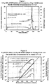
- Figure 1 illustrates the HWS strategy and the use of the new, TIAX manufactured ARC to obtain heat of decomposition and reaction kinetics on a sample of di-tert-butyl-peroxide in a lightweight, spherical, titanium bomb.
- 6 grams of a 20% solution of DTBP in toluene was heated in a 6 gram titanium bomb to an initial starting temperature of 95 °C.
- An exotherm was detected at 110.5 °C after several heating steps and followed adiabatically to reaction completion.
- the DIERS Bench Scale Apparatus was developed and commercialized by Fauske and Associates (4,5) as the VSPTM.
- the apparatus was designed to characterize chemical systems subject to thermal runaway and to calculate a vent size for a particular reactor from measurements of the temperature and pressure rates made in the apparatus.
- This device overcame the main disadvantage of the ARC, the high ⁇ factor, but at a cost of loss of sensitivity.
- a relatively large sample size was required and the device required complex, high-pressure plumbing and a 'containment vessel' for the pressure balancing system.
- Competitive machines such as the APTACTM (6,9) and the Phi-TecTM (7) also suffered from similar disadvantages, although the APTAC does retain the sensitivity of the ARC.
- the differential scanning calorimeter is also extensively used for obtaining information on thermal events in materials.
- pressure measurements are not usually made due to the small sample size employed ( ⁇ 1-20 mg).
- reactant addition during the test and sample stirring are problematic with the DSC and because it is a scanning method at a constant heat rate, the data cannot be easily scaled to full size equipment which may be handling or storing the material being tested.
- EP 1 184 649 A1 discloses a calorimeter comprising a bomb ("Reaktor 1") having an interior space for a sample and an external insulating wall (“Isolationsmaterial 17"), which partially encloses the bomb and partially is opened, wherein a metal block enclosing the bomb is coupled via Peltier elements to an exterior thermostat.
- a sample heater is integrated in a first closed loop control (“A") constituting an inner thermostat for providing a constant sample temperature.
- a loss of heat from an exterior surface of the bomb is essential for the measurement principle.
- the "intermediate thermostat” constituted by the metal block and associated second closed loop control (“B”) safeguards a constant temperature at the exterior surface of the bomb, which is different from the sample temperature, so that heat flows through the wall of the bomb.
- US 4,670,404 discloses a test equipment and a test method by which a measurement of the thermal properties of a sample undergoing an exothermic reaction can be conducted under adiabatic conditions.
- this equipment can be regarded as an adiabatic calorimeter comprising a bomb having an interior space for a sample, an external insulating wall enclosing the bomb, and at least one guard heater within the wall and external to the bomb, wherein said guard heater or heaters having at least one associated thermocouple, so that by means of a closed loop control a temperature at an external surface of the bomb is controlled to be equal the sample temperature.
- US 3,365,944 discloses an adiabatic calorimeter, in which an amount of power to be provided to a sample heater is a constant power and as a result of the measurement there is recorded the temperature of the sample as a function of time.
- this object is solved by a calorimeter according to claim 1 and methods for use in a calorimeter according to any of claims 10, 12, 14 and 15, respectively.
- the dependent claims are directed to advanteagous further developments of the invention.
- An improved calorimeter using a new adiabatic technique has been developed.
- the technique may be embodied in new calorimeters.
- existing equipment can be modified to allow use of the new techniques, although the advantages of using the method on older machines may be limited by the small maximum heating rate the machines can accurately track.
- the improved calorimeter comprises a sample bomb and a bomb thermocouple, one or more guard heaters and thermocouples for the guard heaters and optionally a thermocouple for the sample.
- the sample bomb is equipped with a sample heater positioned inside the bomb, or in or on the wall of the bomb itself or in or on the wall of an associated heat sink.
- the sample heater regulated by a controller via feedback from one or more thermocouples, emits heat into the sample at a rate that is programmed to increase the temperature of the sample and of the bomb at a constant preselected rate.
- the heat output of the sample heater is decreased during sample exotherms, and increased during sample endotherms, to maintain the selected rate.
- the improved calorimeter has provisions to input heat into the sample at a rate proportional to the heating rate of the sample in order to compensate for the heat loss from the sample to the sample bomb during an exothermic reaction.
- the sample heater may be placed outside the sample in a heat sink which is in good thermal contact with the bomb. Using this configuration, the sample heating rate is controlled at a constant rate throughout the exotherm.
- the calorimeter may contain more than one bomb, each bomb having an associated sample heater and bomb thermocouple such that several samples may be simultaneously scanned at the same temperature rate in the same adiabatic environment.
- the apparatus further comprises one or more of a pressure sensor, a stirring motor or other stirring device, and a cooling capacity allowing measurements to begin at sub-ambient temperatures.
- the calorimeter may have only one thermocouple, other than guard heater thermocouples, to estimate the sample and bomb temperature.
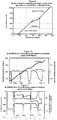
- Figures 1 and 2 show tests with a model substance (DTBP; di-tert-butyl peroxide) in a prior art ARC machine.
- Figure 3 is a schematic drawing of the improved calorimeter of the invention.
- Figures 4 , 5 and 6 show plots with DTBP on the new apparatus.
- Figures 7 and 8 show different types of plots with the inventive apparatus for the model material.
- Figure 9 shows the sample heater output during an exotherm.
- Figure 10 shows the detection of multiple endotherms in a material.
- Figures 11 and 12 show multiple exotherms and endotherms in scans of, respectively, ammonium nitrate and hydrogen peroxide.
- Figure 13 shows compensation at a ⁇ of other than 1.0.
- Figure 14 shows a modified bomb with a heat sink providing extra mass for use with highly exothermic samples.
- Figures 15 and 16 show measurements of the exotherm of DTBP with the heat sink of Fig. 14 , at various heating rates.
- Figures 17 and 18 show exotherm measurements with hydrogen peroxide, and demonstrate pressure measurement.
- the invention comprises both an improved calorimeter, and improved measurements and measurement techniques that are made possible by the improved calorimeter.
- the calorimeter is shown schematically in figure 3 .
- the calorimeter comprises a sample reaction vessel or bomb 1, an enclosure 2, guard heaters 3 connected to enclosure 2, sample heater 4, first (outer bomb) thermocouple 6, optional second (sample) thermocouple 5, sample 7, and outer surface 8 of the bomb 1.
- Each of the guard heaters 3, of which there are typically one to four, has an associated thermocouple (not shown).
- Each of the several thermocouples provides data to a controller (not illustrated).
- the controller regulates the amount of heat provided by the sample heater 4 and each guard heater 3.
- the controller also records the data from the thermocouples and performs calculations to select the amount of power to be provided to the sample heater 4 and the guard heaters 3.
- the guard heaters 3 are typically wound as coils around an enclosure 2 which fits closely around the bomb 1. They may also be formed as a coil on a lid of the apparatus or the enclosure 2 (not illustrated). In some embodiments, a guard heater coil is wound around the upper end of the "stem" 9 of the bomb to prevent heat leakage by conduction.
- a particular rate of temperature increase that is to be applied to the sample is selected. The sample heating rate is detected by the sample thermocouple 5 and the first, outer bomb wall thermocouple 6. The power supplied to the sample heater 4 is regulated to obtain the desired rate of heating.
- the first, outer thermocouple 6 senses the outside temperature of the bomb 1.
- the guard heater 3 temperature is controlled at the same temperature as the temperature of the outside surface 8 of the bomb wall in order to maintain adiabatic conditions around the sample bomb 1.
- the sample 7 temperature may be estimated from the measured temperature and rate of temperature rise of the outer bomb wall 8, thus eliminating the need for the sample thermocouple.
- the bomb wall thickness and thermal conductivity are preferably known, relative to a standard bomb which has been calibrated in a prior experiment.
- the sample 4 will undergo a change.
- This may be an endothermic change, such as a melting or a phase transition; or it may be an exothermic change, which can be a phase transition or can be a decomposition or other chemical change.
- the sample heater power output is increased to keep the rate of temperature rise constant.
- the applied sample heater power may be controlled at a constant rate during an endotherm. Under these conditions, the rate of temperature rise of the sample will fall toward zero and the guard heaters surrounding the sample bomb will maintain adiabatic conditions.
- the power supplied to the sample heater is decreased to keep the sample temperature rate constant.
- the rate of heat loss from the sample to the sample bomb is continuously calculated.
- the sample power output has decreased to equal the heat loss rate to the sample bomb, the sample power output is adjusted to be equal to the heat loss rate to the sample bomb for the remaining duration of the exotherm, thus eliminating the effect of the mass of the bomb on the course of the exothermic reaction.
- the sample heating rate will accelerate above the initially controlled, steady state heating rate.
- the guard heater temperature rate is also increased to maintain adiabatic conditions around the sample bomb.
- sample bombs 1 optionally surrounded by heat sinks 11 may be heated at the same rate of temperature rise within the adiabatically controlled heated space surrounding the sample bombs.
- each sample and heat sink has a separately controlled sample heater so that multiple samples may be simultaneously tested in the apparatus.
- the many potential sources of heat loss from a sample in an adiabatic environment include:
- a well-designed adiabatic calorimeter will minimize the source of these losses (or gains) and the TIAX ARC achieves excellent adiabaticity by good design, good control algorithms and automated thermocouple calibration checks.
- a further source of loss is heat loss to the bomb wall from the reacting sample.
- ⁇ factor 1.0 + M b C b / M s C s
- M mass
- C heat capacity
- subscripts b and s refer to the sample bomb and the sample respectively.
- ⁇ factors for experimental adiabatic calorimeters tend to be about 1.5 - 3.0 because the reaction vessel needs to be strong enough to contain the reaction products at high temperature and pressure. A large fraction of the reaction energy is therefore absorbed by the reaction vessel, which significantly changes the temperature and pressure-time histories.
- a ⁇ factor of 2.0, for instance, means that one half the reaction heat will be absorbed by the bomb.
- the ARC manages a heavy walled bomb by keeping the 'system' adiabatic where the system is the sample and the bomb. In this case, the sample and the bomb must be at the same temperature throughout the exotherm. In the event that the sample temperature rises significantly above the bomb wall temperature the data will be subject to serious errors.
- Figure 3 represents a heavy walled sample reaction vessel 1 in an adiabatic environment inside an enclosuere 2.
- the temperature of the sample 7, T s is measured using an optional but preferred thermocouple 5 (called the "second" thermocouple), and the temperature of the exterior wall of the sample vessel, T w , is measured using a first thermocouple 6.
- the sample 7 and the reaction vessel 1 are heated at a constant rate by a small heater 4 in contact with the sample 7.
- the heating rate is chosen such that the sample temperature, T s , is essentially at the same temperature, T w , as the outside wall 8 of the bomb 1.
- Guard heaters 3 surrounding the reaction vessel prevent any heat losses from the system by conduction, radiation or convection. If the sample 7 begins to evolve heat, the sample heater 4 is controlled such that the overall rate of temperature rise remains constant. If the sample exhibits endothermic behavior, the sample heater 4 output is increased to keep the temperature rate constant.
- High viscosity liquids and solids can also be measured if heating rates are kept low. Solid, particulate materials and high viscosity liquids would tend to decrease the heat transfer rate from the heater to the material and also from the material to the interior wall of the sample bomb. Heating rates must necessarily then be kept lower in order to ensure adequate thermal equilibrium throughout the system.
- Equation 2 above may be modified by the factor ⁇ , representing the fraction of the mass of the bomb that is to be compensated by addition of heat from the sample heater.
- the factor ⁇ varies from zero where no compensation occurs to unity where the mass of the bomb is fully compensated.
- the sample temperature and the outside bomb wall temperature will tend to diverge during an exotherm, it is important to choose the correct temperature to represent the sample temperature. If the heat loss compensation is zero then the relevant temperature to use for the 'sample' will be the outside wall temperature, as in a prior art ARC experiment. This temperature should be essentially the same as the inside wall temperature. If the heat loss compensation is such that the effective ⁇ for the experiment is greater than 1.0, then the temperature to use will be the temperature of the sample liquid, or of the inside bomb wall.
- the sample and the bomb are initially heated at a constant heating rate using the sample heater. Heat losses are prevented by careful control of the environmental temperature. At some point during the temperature scan the sample will typically begin to evolve heat. The heater output is then adjusted (reduced) sufficiently to control the heating rate at the initial set rate. During this time period the sensible heat stored in the sample and the sample bomb has therefore partly come from the sample and partly from the heater. When the heater output reaches the level required to fully compensate for the thermal inertia of the bomb, as given by equation [3], the system temperature rate is allowed to accelerate and the heater output is controlled according to equation [3].
- the heater to which the fitting is attached is run at a slightly higher temperature than the temperature of the sample bomb.
- the temperature elevation is dependent on the rate of temperature scan at which the test is run.
- the magnitude of the temperature elevation is obtained in a prior calibration test using water in a sample bomb and heating the system at a number of temperature rates.
- FIG 4 shows the temperature-time profiles for three tests using a 10% solution in a 6 gram titanium bomb and heated at 0.5, 1.0 and 2.0 °C/min.
- the first and later portions of each temperature-time plot represent forced heating of the sample and bomb at a constant rate. It is possible to extract heat capacity estimates from this data since the heater energy required to heat the system is known.
- the central portion of each plot is the temperature rise associated with the exothermic decomposition of the DTBP. During this part of the test the thermal mass of the bomb is totally compensated by addition of heat to the sample at a rate given by equation [3]. This is more clearly shown in figure 5 where the logarithm of the heating rate is plotted as a function of reciprocal temperature.
- FIG. 6 is a plot of the self-heating rate and the first order rate, k, for the decomposition where the rate is calculated from the self-heat rate and the temperature rise for the sample (see ref (1) and discussion under Activation Energy' below).
- the first order rate and subsequently the activation energy and pre-exponential factors for all tests listed in Table 1 were calculated from equation [4] using the data measured during the bomb compensation phase of the experiment.
- k dT / dt / T f ⁇ T
- the expression enables the calculation of the energy and power output from the sample as a function of temperature provided that the heat capacities of the sample and the bomb are known. Alternatively, if there is no exothermic heating, then the heat capacity of the sample may be determined, as a function of temperature, if the heat capacity of the sample bomb is known or has been measured in a prior experiment. If the heat capacities of the sample and the bomb are both unknowns the combined heat capacities are directly measured prior to and after any exothermic or endothermic behavior.
- C / C 0 W f ⁇ W / ⁇ W an expression can be derived which relates the measured energy output to the kinetics.
- C is the concentration of a single reactant at any temperature
- C 0 is the initial concentration
- W f is the final energy output level due to the reaction
- W is the energy output at any temperature
- equations [9], [10], [11] and [16] allow the early detection of an exothermic event during the time period when the heating rate is constant. Moreover, the heat output from the reaction is continuously summed during the scanning period.
- Figure 7 shows the heater power output, dH/dt, and the sample power output, dW/dt, as a function of time.
- Figure 8 is a logarithmic plot of the heater power output, the sample power output, the sample temperature rate and the rate of pressure rise as a function of reciprocal temperature.
- two plots are shown on the graph which represent the 1 st order reaction rate constant calculated using equation [16] and also the same rate constant calculated using the temperature rate data after 145 °C and equation [4]. It is not possible to use the temperature rate data prior to 145 °C because the rate is constant and therefore no information can be extracted.
- the two lines give essentially the same activation energies and pre-exponential factors, as may be seen in the plot. The average value of the activation energy was found to be 36.88 Kcal/mol and the heat of reaction was 367 cal/g DTBP.
- the heater power is used to heat both the sample and bomb at the given temperature scan rate. If the system has been well calibrated and heat losses are zero, then the specific heat of the sample may be obtained as a function of temperature, provided that the specific heat and mass of the sample bomb are known.
- FIG. 9 shows a typical test result obtained on a sample of DTBP heated at 0.5 °C/min in a 18 gram stainless steel bomb. The plot also shows that as the sample begins to evolve heat, the energy output from the heater decreases. The heat capacity of the system cannot be determined when the sample is thermally active. It has also been found that the function is very sensitive to the temperature of the top heater. The top heater is used to heat the high-pressure fitting to which the sample bomb is attached. Therefore, very small heat losses to the fitting can affect the estimated value of the specific heat, especially if the sample mass is small and the sample bomb mass is relatively large.
- the average specific heat of the sample was determined to be 0.505 cal/g°C.
- the apparent value of the specific heat after completion of the decomposition was similarly determined to be 0.592 cal/ g°C.
- Endotherms are easily quantified using the sample heater and either a fixed temperature scanning mode or a fixed power output from the heater.
- a test was conducted on a sample of ammonium nitrate in order to demonstrate that the method could be used both for solid materials and for a sample exhibiting endothermic behavior.
- Ammonium nitrate exhibits four separate endotherms between ambient temperature and about 170 °C. Above about 170 °C ammonium nitrate decomposes violently. The test was terminated before this event because of the relatively large size of the sample.
- FIG. 10 shows the sample temperature and the sample power as a function of time. The figure clearly shows four endotherms, at 37°C, 86°C, 126°C and fusion of the solid starting at about 150°C.
- Figure 11 shows the sample power and energy as a function of the sample temperature and also the apparent sample heat capacity as a function of temperature.
- the sample heat capacity is indeterminate.
- the heat capacity was determined from the heater power output and the known mass and heat capacity of the stainless steel bomb, as described above.
- the heat of fusion was estimated at 18.1 cal/g at 168°C, which is in good agreement with the published value [10].
- the estimated heat of decomposition was between about 340 and 360 cal/g of DTBP.
- Tou and Whiting [2] report values ranging from about 230 to 335 cal/g depending on the mass and type of bomb used in the experiment.
- Leung, Fauske and Fisher [5] report a value of 290 cal/g measured in the VSP apparatus while Ming-Huei Yue [8] reports an average value of 331 cal/g in the EAC apparatus.
- An average value of 335 cal/g from round robin testing is reported in [11]. The value found in this work therefore, appears to be high by 7-8%.
- the ability to compensate for the thermal mass of the reaction vessel using a sample heater depends on a number of factors.
- the principal limitations are the ability to transfer energy from the heater to the sample and the uniform distribution of that heat to the sample bomb. Stirring of the sample is a necessity if heat rates exceed more than a few tens of degrees per minute. If energy rates are very high, the sample heater surface temperature may also exceed the temperature of the sample by a considerable amount, perhaps leading to elevated reaction rates at the surface of the heater. Sample temperature rates as high as 150 °C/min have been observed in this work. The maximum power available from the sample heater was about 80 cal/min, thus limiting the mass of the bomb that could be successfully compensated.
- FIG. 13 shows the result of a test with a 16.7 % solution of DTBP in a 10.6 g stainless steel bomb, ramped at 2.0 °C/min and compensated for 60% of its mass. It may be seen that the heating rate exceeded 100 °C/min and the peak heater power reached its maximum output of about 80 cal/min. Also shown is the apparent sample specific heat as a function of temperature up to the point where exothermic activity occurs. The activation energy for this test was found to be 36.62 Kcal/mol.
- the sample temperature rate continuously increases as the exotherm proceeds. Since the self-heating rate is proportional to the reaction rate the kinetics can be derived from the measured temperature rates.
- the heating rate for the system consisting of the sample and the sample bomb, is controlled at a constant rate by adjusting the power output of the sample heater. As the exotherm accelerates in rate the heater output is decreased in order to keep the rate of heating of the system constant. Therefore, the rate of change of the heater output becomes effectively the new measure of the rate of reaction, and not the rate of change of temperature as in the ARC.
- the temperature rate in this method is constant and therefore no kinetic information can be extracted using the temperature rate.
- the sample bomb should be heavy enough to absorb the heat of reaction without increasing the constant rate of temperature rise.
- a heavy walled bomb has the disadvantage that heat conduction from the interior to the outside wall will be slow, especially since sample bombs would normally be constructed of stainless steel or a similar alloy where the thermal conductivity is small. Higher conductivity materials are generally unsuitable because of their lack of strength at higher temperatures, their expense (in the case of precious metals) or their chemical reactivity.
- a thinner walled bomb in a material such as stainless steel may be used along with a sleeve of high conductivity material such as copper, as illustrated in figure 14 .
- the copper may be, but not necessarily heated from the outside by the 'sample' heater but the operation of the apparatus is in all other aspects the same as that described.
- the advantages of this type of sample bomb are that higher temperature scanning rates may be used without compromising the thermal conductivity, a sample heater is not required to be inserted into the sample vessel and the sample vessel is less expensive and disposable.
- the ⁇ factor for a test of this type does not have a meaning since the energy absorbed by the bomb has two sources, the sample heat of reaction and the varying output from the heater.
- the effective thermal mass of the bomb relative to the sample therefore changes as the output of the sample heater changes. Since the heat capacity of the sample bomb is known and the power output from the heater is known, the variation of the ⁇ factor with sample temperature can be calculated if desired.
- the average heat of reaction was found to be 379.0 cals/g of DTBP, which is about 6.0% higher than the value found by the bomb compensation method, as described in section 2. Note that this method does not require knowledge of the sample heat capacity or the bomb heat capacity in order to obtain the heat of reaction.
- the value of the factor, ⁇ , in equation [3] is set to zero and no compensation for the thermal mass of the bomb occurs.
- Figure 16 shows the heater power and the first order reaction rate constant as a function of the reciprocal of the sample temperature for each of the four tests which are shown in the plot.
- the first order rate constant was calculated using equation [16] and the slopes of the lines gave the activation energy and the pre-exponential factor.
- the average activation energy for the four tests was 37.20 Kcal/mol, which is about 1.2% greater than the average value found for the bomb compensation method (see Table 1).
- Figure 18 shows the pressure in the reaction bomb as a function of the sample temperature. At 100 °C, the pressure was 1420 KPa. Assuming that the oxygen was insoluble in the water at that temperature and that the head space in the reaction vessel was 6.42 mls, this agreed reasonably well with the calculated pressure of 1438.9 KPa, thus confirming the full decomposition of the hydrogen peroxide sample.
- Cooling means can be, among others, a conventional refrigeration or freezing unit, a device for passing chilled gas through the apparatus, for example from liquid nitrogen or other liquefied or solidified gas (for example, carbon dioxide, argon, helium, or other convenient gas), or simply operating the unit in a chilled environment (walk in refrigerator or freezer).
- a conventional refrigeration or freezing unit a device for passing chilled gas through the apparatus, for example from liquid nitrogen or other liquefied or solidified gas (for example, carbon dioxide, argon, helium, or other convenient gas), or simply operating the unit in a chilled environment (walk in refrigerator or freezer).
- Another option is stirring of the sample, which is particularly useful with samples which are liquid, or in some cases present as fine and preferably non-aggregating powders.
- a magnetic stirrer with a stirring magnet inside the bomb and a drive magnet outside, has been used in commercial apparatuses.
- a mechanical stirrer would also be possible, although access through the neck of the bomb is restricting.
- Another option is measurement of the pressure produced by the sample during thermal analysis. This is currently done in some commercial calorimeters.
- the bomb can be sealed, for example periodically during the run, or for all of a run over a narrow temperature range, and the pressure inside the bomb is measured by a pressure transducer or other sensor.
- An alternative, which allows sealing of the bomb over a wide pressure range, is to place the bomb and the enclosure inside a pressurizable container, and then applying external pressure to balance the pressure found inside the bomb. Such a procedure is currently used, and could be used in the calorimeter of the invention, to allow the use of thin-walled bombs, which would absorb less heat from the sample.
- the sample size is not a critical aspect of the invention.
- the sample is not limited in amount, and does not have a strong exotherm or decomposition, the range of 1 to 5 grams is convenient. There is seldom a need for larger samples, unless a very subtle exotherm or endotherm is to be measured accurately. Smaller samples may be used, depending on the sensitivity and precision required, which may be as small as 100 mg.
- the sample volume in the bomb will be adjusted accordingly.
- a typical bomb volume will be in the range of about 1 cc to 20 cc, but may be made larger or smaller as required to accommodate a sample.
- heating rates a wide range of heating rates is possible.
- An upper rate could be in the range of 1500 calories/minute, or about 100 W, but lower rates can be used down to the limits of sensitivity and stability. These can be as low as about 0.0001 calorie per minute, or about 5 to 7 microwatts.
- the ability to measure over such a wide range of heating rates is an advantage of the present invention, that is not found in other systems.
- thermocouple typically a type N thermocouple.
- Thermistors can be used, especially below about 100 deg. C.
- the sample heater side can be inside the wall of the bomb, or inside the wall of a heat sink or high-heat-conductivity material that is in thermal contact with the bomb, and still provide all of the benefits of the invention.
- the sample heater can be mounted on the outside of the bomb. This will provide similar results when the rate of heating can be constant, particularly with a well calibrated bomb, but is much harder to use to track an exotherm, especially a "runaway" exotherm.
- An improved method has been developed for obtaining adiabatic calorimetry data using a sample heater to quantify thermal events.
- the method uses a sample size of the order 1-5 gram so that pressure is also routinely measured.
- the effect of the mass of the reaction vessel on the results can be negated by dynamic thermal compensation, such that the effective ⁇ factor for the test can be 1.0.
- Heat effects from the sample, including endothermic events, are quantified without reference to the specific heat of the sample.
- the sample and reaction vessel can be heated at a constant temperature rate and thus dramatically reduce testing time over that for conventional adiabatic calorimetry using the Heat-Wait-Search strategy. Sample specific heats can be measured prior to any thermal event.
- the exotherm detection sensitivity is at least as good as existing adiabatic calorimeters employing the HWS strategy, although the detection sensitivity is dependent on the temperature scanning rate.
- Patents describing calorimeters include US patents 3,593,577 ; 4,208,907 ; 4,439,048 ; 4,892,707 ; 4,963,499 ; 5,547,282 ; 5,806,979 ; 6,157,009 and 6,513,969 ; WO 99/60356 ; EP 0 286 580 ; and the abstract of Japanese application 53049395 .
Landscapes
- Chemical & Material Sciences (AREA)
- Physics & Mathematics (AREA)
- General Physics & Mathematics (AREA)
- Engineering & Computer Science (AREA)
- Combustion & Propulsion (AREA)
- General Health & Medical Sciences (AREA)
- Life Sciences & Earth Sciences (AREA)
- Analytical Chemistry (AREA)
- Biochemistry (AREA)
- Health & Medical Sciences (AREA)
- Immunology (AREA)
- Pathology (AREA)
- Chemical Kinetics & Catalysis (AREA)
- Nonlinear Science (AREA)
- Investigating Or Analyzing Materials Using Thermal Means (AREA)
Description
- The present invention relates to a scanning adiabatic calorimeter and methods for use in such a calorimeter.
- Thermal stability of materials, exothermic reactions, and thermal runaway are very often studied in the Accelerating Rate Calorimeter, more often referred to as the ARC® Scientists at Dow Chemical first developed this device in the late 1970s and many papers describing the use of the ARC have since been written (1,2,3). Using this apparatus, a sample and a sample bomb are heated to a temperature where exothermic activity is detected in the sample by observation of the rate of temperature change of the sample. The sample and bomb are prevented from losing heat to the environment by careful control of guard heaters surrounding the sample bomb. A heating algorithm, commonly referred to as the Heat-Wait-Search™ (HWS) strategy, is used to control the initial heating of the sample and to bring the sample to a stable temperature during the exotherm search period.
-
Figure 1 illustrates the HWS strategy and the use of the new, TIAX manufactured ARC to obtain heat of decomposition and reaction kinetics on a sample of di-tert-butyl-peroxide in a lightweight, spherical, titanium bomb. In thisexperiment 6 grams of a 20% solution of DTBP in toluene was heated in a 6 gram titanium bomb to an initial starting temperature of 95 °C. An exotherm was detected at 110.5 °C after several heating steps and followed adiabatically to reaction completion. (Note the"steps"at the left and right sides of the scan.) The heat of decomposition was estimated at 49.35 Kcal/mol of DTBP using an average heat capacity of 0.51 cal/g °C for the sample solution and 0.135 cal/g °C for the titanium bomb.Figure 2 shows the heating rate and pressure rate of the sample as a function of reciprocal temperature and also the 1st order reaction rate for the decomposition reaction, as calculated from the exotherm portion of the heat rate plot (1). The activation energy and pre-exponential factor for the reaction agree well with published data (2). - While the ARC is a sensitive and stable adiabatic calorimeter, it suffers from a number of significant drawbacks.
- The thermal mass of the sample bomb is often large in comparison to the sample such that a large fraction of the heat released by the sample is absorbed by the bomb, resulting in lowered peak reaction temperatures and pressures. In other words, most tests are run with a relatively large Φ factor.
- The heaters on the older style ARCs are confined to a temperature rate below about 15 °C/min, although the newer TIAX ARC is capable of tracking heat rates to 250 °C/min. This greater tracking rate is, of course, only of utility if the sample and bomb are in thermal equilibrium throughout the exotherm.
- The time required to complete a test using the HWS strategy often exceeds twenty-four hours so that productivity per machine is very low.
- The apparatus is not capable of quantifying endothermic behavior.
- Stirring, on the older style ARCs, although possible, is very expensive and therefore not often used.
- In the early 1980s, the DIERS Bench Scale Apparatus was developed and commercialized by Fauske and Associates (4,5) as the VSP™. The apparatus was designed to characterize chemical systems subject to thermal runaway and to calculate a vent size for a particular reactor from measurements of the temperature and pressure rates made in the apparatus. This device overcame the main disadvantage of the ARC, the high Φ factor, but at a cost of loss of sensitivity. In addition, a relatively large sample size was required and the device required complex, high-pressure plumbing and a 'containment vessel' for the pressure balancing system. Competitive machines such as the APTAC™ (6,9) and the Phi-Tec™ (7) also suffered from similar disadvantages, although the APTAC does retain the sensitivity of the ARC.
- The differential scanning calorimeter (DSC) is also extensively used for obtaining information on thermal events in materials. However, pressure measurements are not usually made due to the small sample size employed (∼1-20 mg). Also, reactant addition during the test and sample stirring are problematic with the DSC and because it is a scanning method at a constant heat rate, the data cannot be easily scaled to full size equipment which may be handling or storing the material being tested.
-
EP 1 184 649 A1Reaktor 1") having an interior space for a sample and an external insulating wall ("Isolationsmaterial 17"), which partially encloses the bomb and partially is opened, wherein a metal block enclosing the bomb is coupled via Peltier elements to an exterior thermostat. A sample heater is integrated in a first closed loop control ("A") constituting an inner thermostat for providing a constant sample temperature. A loss of heat from an exterior surface of the bomb is essential for the measurement principle. The "intermediate thermostat" constituted by the metal block and associated second closed loop control ("B") safeguards a constant temperature at the exterior surface of the bomb, which is different from the sample temperature, so that heat flows through the wall of the bomb. -
US 4,670,404 discloses a test equipment and a test method by which a measurement of the thermal properties of a sample undergoing an exothermic reaction can be conducted under adiabatic conditions. Insofar, this equipment can be regarded as an adiabatic calorimeter comprising a bomb having an interior space for a sample, an external insulating wall enclosing the bomb, and at least one guard heater within the wall and external to the bomb, wherein said guard heater or heaters having at least one associated thermocouple, so that by means of a closed loop control a temperature at an external surface of the bomb is controlled to be equal the sample temperature. -
US 3,365,944 discloses an adiabatic calorimeter, in which an amount of power to be provided to a sample heater is a constant power and as a result of the measurement there is recorded the temperature of the sample as a function of time. - It is an object of the present invention to provide a scanning adiabatic calorimeter and a method for use in a scanning adiabatic calorimeter by which a novel adiabatic technique is realized.
- According to the invention, this object is solved by a calorimeter according to
claim 1 and methods for use in a calorimeter according to any ofclaims - An improved calorimeter using a new adiabatic technique has been developed.. The technique may be embodied in new calorimeters. In some cases, existing equipment can be modified to allow use of the new techniques, although the advantages of using the method on older machines may be limited by the small maximum heating rate the machines can accurately track.
- In one aspect, the improved calorimeter comprises a sample bomb and a bomb thermocouple, one or more guard heaters and thermocouples for the guard heaters and optionally a thermocouple for the sample. The sample bomb is equipped with a sample heater positioned inside the bomb, or in or on the wall of the bomb itself or in or on the wall of an associated heat sink. The sample heater, regulated by a controller via feedback from one or more thermocouples, emits heat into the sample at a rate that is programmed to increase the temperature of the sample and of the bomb at a constant preselected rate.
- In another aspect of the invention, the heat output of the sample heater is decreased during sample exotherms, and increased during sample endotherms, to maintain the selected rate.
- In another aspect, the improved calorimeter has provisions to input heat into the sample at a rate proportional to the heating rate of the sample in order to compensate for the heat loss from the sample to the sample bomb during an exothermic reaction.
- In another aspect, the sample heater may be placed outside the sample in a heat sink which is in good thermal contact with the bomb. Using this configuration, the sample heating rate is controlled at a constant rate throughout the exotherm.
- In another aspect, the calorimeter may contain more than one bomb, each bomb having an associated sample heater and bomb thermocouple such that several samples may be simultaneously scanned at the same temperature rate in the same adiabatic environment.
- In another aspect, the apparatus further comprises one or more of a pressure sensor, a stirring motor or other stirring device, and a cooling capacity allowing measurements to begin at sub-ambient temperatures.
- In another aspect, the calorimeter may have only one thermocouple, other than guard heater thermocouples, to estimate the sample and bomb temperature.
- Further aspects of the invention will be evident from the description.
-
Figures 1 and 2 show tests with a model substance (DTBP; di-tert-butyl peroxide) in a prior art ARC machine.Figure 3 is a schematic drawing of the improved calorimeter of the invention.Figures 4 ,5 and 6 show plots with DTBP on the new apparatus.Figures 7 and 8 show different types of plots with the inventive apparatus for the model material.Figure 9 shows the sample heater output during an exotherm.Figure 10 shows the detection of multiple endotherms in a material.Figures 11 and12 show multiple exotherms and endotherms in scans of, respectively, ammonium nitrate and hydrogen peroxide.Figure 13 shows compensation at a Φ of other than 1.0.Figure 14 shows a modified bomb with a heat sink providing extra mass for use with highly exothermic samples.Figures 15 and 16 show measurements of the exotherm of DTBP with the heat sink ofFig. 14 , at various heating rates.Figures 17 and 18 show exotherm measurements with hydrogen peroxide, and demonstrate pressure measurement. - The invention comprises both an improved calorimeter, and improved measurements and measurement techniques that are made possible by the improved calorimeter.
- The calorimeter is shown schematically in
figure 3 . The calorimeter comprises a sample reaction vessel orbomb 1, anenclosure 2,guard heaters 3 connected toenclosure 2,sample heater 4, first (outer bomb)thermocouple 6, optional second (sample)thermocouple 5,sample 7, andouter surface 8 of thebomb 1. Each of theguard heaters 3, of which there are typically one to four, has an associated thermocouple (not shown). Each of the several thermocouples provides data to a controller (not illustrated). The controller regulates the amount of heat provided by thesample heater 4 and eachguard heater 3. The controller also records the data from the thermocouples and performs calculations to select the amount of power to be provided to thesample heater 4 and theguard heaters 3. - The
guard heaters 3 are typically wound as coils around anenclosure 2 which fits closely around thebomb 1. They may also be formed as a coil on a lid of the apparatus or the enclosure 2 (not illustrated). In some embodiments, a guard heater coil is wound around the upper end of the "stem" 9 of the bomb to prevent heat leakage by conduction.
In operation, a particular rate of temperature increase that is to be applied to the sample is selected. The sample heating rate is detected by thesample thermocouple 5 and the first, outerbomb wall thermocouple 6. The power supplied to thesample heater 4 is regulated to obtain the desired rate of heating. - Meanwhile, the first,
outer thermocouple 6 senses the outside temperature of thebomb 1. Theguard heater 3 temperature is controlled at the same temperature as the temperature of theoutside surface 8 of the bomb wall in order to maintain adiabatic conditions around thesample bomb 1. - In an alternative mode, the
sample 7 temperature may be estimated from the measured temperature and rate of temperature rise of theouter bomb wall 8, thus eliminating the need for the sample thermocouple. In addition, in this alternative mode the bomb wall thickness and thermal conductivity are preferably known, relative to a standard bomb which has been calibrated in a prior experiment. - At some temperature (or more than one), the
sample 4 will undergo a change. This may be an endothermic change, such as a melting or a phase transition; or it may be an exothermic change, which can be a phase transition or can be a decomposition or other chemical change. - When the change is an endotherm, the sample heater power output is increased to keep the rate of temperature rise constant. Alternatively, and preferably, the applied sample heater power may be controlled at a constant rate during an endotherm. Under these conditions, the rate of temperature rise of the sample will fall toward zero and the guard heaters surrounding the sample bomb will maintain adiabatic conditions.
- When the change is an exotherm, the power supplied to the sample heater is decreased to keep the sample temperature rate constant. The rate of heat loss from the sample to the sample bomb is continuously calculated. When the sample heater power output has decreased to equal the heat loss rate to the sample bomb, the sample power output is adjusted to be equal to the heat loss rate to the sample bomb for the remaining duration of the exotherm, thus eliminating the effect of the mass of the bomb on the course of the exothermic reaction. Under these circumstances, the sample heating rate will accelerate above the initially controlled, steady state heating rate. The guard heater temperature rate is also increased to maintain adiabatic conditions around the sample bomb. In an alternative mode,
several sample bombs 1, optionally surrounded by heat sinks 11 may be heated at the same rate of temperature rise within the adiabatically controlled heated space surrounding the sample bombs. In this configuration, each sample and heat sink has a separately controlled sample heater so that multiple samples may be simultaneously tested in the apparatus. - The many potential sources of heat loss from a sample in an adiabatic environment include:
- Conduction up the
stem 9 of the reaction vessel (bomb) 1 and along the thermocouple sheath (not illustrated). - Convection losses from the
surface 8 of thebomb 1 - Radiation exchange with the surrounding
heaters 3 - Refluxing by vapor condensation on an optional fitting which seals the reactor and connects it to the pressure transducer (not illustrated.)
- A well-designed adiabatic calorimeter will minimize the source of these losses (or gains) and the TIAX ARC achieves excellent adiabaticity by good design, good control algorithms and automated thermocouple calibration checks. However, a further source of loss is heat loss to the bomb wall from the reacting sample.
- Traditionally, the relative loss to the bomb wall is described by the Φ factor, defined as

- Bomb wall losses are minimized in the APTAC, VSP and Phi-Tec by using thin walled bombs that have a very small thermal mass relative to the sample, so that the Φ factor is approximately 1.1 or less. However, a number of disadvantages arise from using a thin-walled reaction vessel, including:
- A pressure containment vessel and associated pressure balancing system is typically required to prevent bomb rupture.
- It is difficult to control heat losses from the sample as the pressure changes, sometimes very rapidly, within the containment vessel.
- There are practical limitations to the rate of pressure rise that can be 'balanced', arising from the control of the rate of flow of inert gas to the containment vessel.
- Bomb rupture is not infrequent, leading to messy clean-ups and downtime while the machine is cleaned and re-calibrated.
- An alternative method to account for the mass of the reaction vessel during an adiabatic experiment has been developed. The method involves the use of a small, computer controlled, heater immersed in the sample. Software continuously calculates the heat lost to the bomb from the sample during an exothermic event. The power from the heater is controlled to equal the rate of heat loss from the sample to the bomb. Thus, the net heat loss is zero. Using the same heater it is also possible to measure energy absorbed by the sample during the heat up phase of the experiment and therefore to calculate a heat capacity for the sample or to quantify any endothermic activity which takes place in the sample.
-
Figure 3 represents a heavy walledsample reaction vessel 1 in an adiabatic environment inside anenclosuere 2. The temperature of thesample 7, Ts, is measured using an optional but preferred thermocouple 5 (called the "second" thermocouple), and the temperature of the exterior wall of the sample vessel, Tw, is measured using afirst thermocouple 6. Thesample 7 and thereaction vessel 1 are heated at a constant rate by asmall heater 4 in contact with thesample 7. The heating rate is chosen such that the sample temperature, Ts, is essentially at the same temperature, Tw, as theoutside wall 8 of thebomb 1.Guard heaters 3 surrounding the reaction vessel prevent any heat losses from the system by conduction, radiation or convection. If thesample 7 begins to evolve heat, thesample heater 4 is controlled such that the overall rate of temperature rise remains constant. If the sample exhibits endothermic behavior, thesample heater 4 output is increased to keep the temperature rate constant. - To analyse the experimental data, the following assumptions are made in the equations and procedures below, unless otherwise stated:
- The sample is at a uniform temperature.
- The inside bomb wall temperature is uniform over the entire inner surface area and the outside bomb wall temperature is also uniform although not necessarily equal to the inner surface temperature.
- The inside wall temperature of the reaction vessel is the same as the bulk liquid temperature at all times.
- Heat losses at the outside wall of the sample bomb are zero.
- The wall thickness of the sample bomb is constant throughout the vessel.
- Initially the
sample heater 4 heats thesample 7. Some of the heat is transferred to thebomb 1 walls so that the heater effectively heats both the sample and bomb. Since the bomb is heated entirely by the sample, the rate of heat loss from the sample to the bomb is given by
- In order to achieve the goal of eliminating wall heat losses, the following experimental requirements are necessary:
- The assumptions listed above are valid.
- Accurate measurement of the inside and outside bomb wall temperatures are obtained.
- Heat losses from the system (consisting of the sample and the reaction vessel) by convection, radiation, conduction and refluxing are eliminated.
- Guard heaters surrounding the sample bomb are capable of tracking the increased sample heating rate which is observed when bomb heat losses are eliminated or reduced.
- A computer controlled heater is in good thermal contact with the sample, and is capable of delivering power at the rate given by the above expression.
- Good heat transfer is present between the sample and the bomb. For liquid samples that evolve heat at a rapid rate this can mean that stirring of the sample is necessary.
- Good heat transfer is present between the heater and the sample, which may require sample stirring for liquid samples evolving heat rapidly.
- High viscosity liquids and solids can also be measured if heating rates are kept low. Solid, particulate materials and high viscosity liquids would tend to decrease the heat transfer rate from the heater to the material and also from the material to the interior wall of the sample bomb. Heating rates must necessarily then be kept lower in order to ensure adequate thermal equilibrium throughout the system.
-
Equation 2 above may be modified by the factor λ, representing the fraction of the mass of the bomb that is to be compensated by addition of heat from the sample heater. The factor λ varies from zero where no compensation occurs to unity where the mass of the bomb is fully compensated.
- It is therefore possible to control the rate of heat added to the system for any desired Φ factor from 1.0 to an upper limit set by the total mass of the bomb and the mass of the sample, as given by equation [1] above.
- Since the sample temperature and the outside bomb wall temperature will tend to diverge during an exotherm, it is important to choose the correct temperature to represent the sample temperature. If the heat loss compensation is zero then the relevant temperature to use for the 'sample' will be the outside wall temperature, as in a prior art ARC experiment. This temperature should be essentially the same as the inside wall temperature. If the heat loss compensation is such that the effective Φ for the experiment is greater than 1.0, then the temperature to use will be the temperature of the sample liquid, or of the inside bomb wall.
- In practice, the sample and the bomb are initially heated at a constant heating rate using the sample heater. Heat losses are prevented by careful control of the environmental temperature. At some point during the temperature scan the sample will typically begin to evolve heat. The heater output is then adjusted (reduced) sufficiently to control the heating rate at the initial set rate. During this time period the sensible heat stored in the sample and the sample bomb has therefore partly come from the sample and partly from the heater. When the heater output reaches the level required to fully compensate for the thermal inertia of the bomb, as given by equation [3], the system temperature rate is allowed to accelerate and the heater output is controlled according to equation [3].
- The advantages of using this type of test over the more traditional ARC method include:
- The test time is considerably shortened since the slow HWS portion of the test is eliminated. (It is not necessary to step and wait for equilibrium.)
- Data can be obtained at Φ factors ranging from 1.0 to the maximum value possible for a bomb of any given mass.
- The heat of reaction can be obtained without reference to the heat capacity of the sample, as explained in section 2.3 below
- It is possible to add excess heat to the bomb in a controlled fashion and thus simulate fire exposure to a vessel containing thermally unstable material.
- Heat capacities of the reactants and products of the reaction can be measured from the known heat input before and after the reaction
- Exotherm onset can be detected at lower temperatures, depending on the initial temperature scan rate.
- A number of experiments using DTBP solutions were run to demonstrate the utility of the method. Table 1 lists the tests and summarizes the results. During the portion of the test where the sample heater was used to compensate for the thermal mass of the bomb, the heat capacities of the bombs were assumed to be a function of the temperature and were calculated as follows (Ref. 12):
Titanium: Cp = 0.10105 + 0.00006788.T Stainless Steel: Cp = 0.07390 + 0.00011420.T Hasteloy C: Cp = 0.08681 + 0.00003000.T Table 1. Summary of tests with DTBP solution and thermal compensation of sample bomb Conc. (%) Sample Mass (g) Bomb Type Bomb Mass (g) Scan Rate (C/min) λ ΔHr (Cal/ g) Ea (Kcal/ mol) Log10[A] (sec-1) 20.0 6.0 Ti 6.0 HWS 1.26* 338 36.9 15.54 16.7 3.0 SS 9.8 1.0 1.0 342 36.52 15.28 16.7 4.0 SS 10.6 0.25 1.0 342 36.44 15.33 16.7 4.0 SS 10.6 0.5 0.0 354 37.48 15.8 16.7 4.0 SS 10.6 1.0 0.6 347 36.36 15.27 16.7 4.0 SS 10.6 1.0 0.75 367 37.2 15.69 16.7 4.0 SS 10.6 2.0 0.6 369 36.62 15.4 16.7 4.0 SS 6.35 1.0 0.6 357 37.4 15.75 16.7 4.0 Ti 6.0 0.5 1.0 ---- 36.55 15.3 10.0 5.0 Ti 10.5 0.5 1.0 339 37.27 15.67 10.0 5.0 Ti 18.4 0.5 1.0 349 36.56 15.3 10.0 5.0 SS 18.5 0.25 1.0 354 36.6 15.28 10.0 5.0 SS 18.5 0.5 1.0 353 36.71 15.6 10.0 5.0 SS 18.5 1.0 1.0 352 37.13 15.43 10.0 5.0 SS 18.5 2.0 1.0 379 36.48 15.27 10.0 5.0 SS 18.5 0.25 0.0 376 36.48 15.28 10.0 6.0 Ti 6.0 0.5 1.0 ---- 36.67 15.36 10.0 6.0 Ti 6.0 1.0 1.0 ---- 36.06 15.07 10.0 6.0 Ti 6.0 2.0 1.0 ---- 36.05 15.05 AVERAGE 355.7 36.76 15.44 *This number is the Φ factor and does not refer to the value λ for this particular test. Also the data were not included in calculating the average values for E, A and ΔH. - In order to minimize conduction heat losses during a transient temperature change, the heater to which the fitting is attached is run at a slightly higher temperature than the temperature of the sample bomb. The temperature elevation is dependent on the rate of temperature scan at which the test is run. The magnitude of the temperature elevation is obtained in a prior calibration test using water in a sample bomb and heating the system at a number of temperature rates. The heater temperature elevation is adjusted until the correct value of the heat capacity of the known mass of water is obtained. It was found that the required temperature elevation could be expressed by an equation of the type:

-
Figure 4 shows the temperature-time profiles for three tests using a 10% solution in a 6 gram titanium bomb and heated at 0.5, 1.0 and 2.0 °C/min. The first and later portions of each temperature-time plot represent forced heating of the sample and bomb at a constant rate. It is possible to extract heat capacity estimates from this data since the heater energy required to heat the system is known. The central portion of each plot is the temperature rise associated with the exothermic decomposition of the DTBP. During this part of the test the thermal mass of the bomb is totally compensated by addition of heat to the sample at a rate given by equation [3]. This is more clearly shown infigure 5 where the logarithm of the heating rate is plotted as a function of reciprocal temperature. As expected, the maximum rate of self-heating and the peak temperature of the exotherm are increased as the forced heating rate during the initial heating stage is increased. The average value for activation energy for this series of tests was 36.4 Kcal/mol. This compared favorably with the value in Ref (7) where the average of sixteen runs from a Round Robin in the VSP apparatus was reported as 36.1 ± 1.0 Kcal/mol. However, this value is a little lower than that reported in Ref (2) where a value of 37.8 ± 1.1 Kcal/mol was found from tests conducted in an ARC. - A second series of tests was run using the same solution but in bombs of differing mass. For the three bombs used in the experiments, the uncompensated Φ factors were 1.26, 1.54 and 1.88.
Figure 6 is a plot of the self-heating rate and the first order rate, k, for the decomposition where the rate is calculated from the self-heat rate and the temperature rise for the sample (see ref (1) and discussion under Activation Energy' below). The first order rate and subsequently the activation energy and pre-exponential factors for all tests listed in Table 1 were calculated from equation [4] using the data measured during the bomb compensation phase of the experiment.
- The calculated kinetic parameters for the three tests are in excellent agreement and similar to the values published in the literature. Clearly, the sample heater has adequately compensated for the masses of the three different bombs, as evidenced by the virtually identical self-heat rate plots for the three tests. Note that in two of the tests, the initial heating rate of the sample was increased in order to decrease the overall test time. Prior to the detected onset of the exotherm, the heating rate was lowered to the desired temperature scan rate of 0.5 °C/min.
- Referring again to
figure [3 ], a simple heat balance on the system gives the following expression
- Therefore, the energy released from the sample is given by


- The expression enables the calculation of the energy and power output from the sample as a function of temperature provided that the heat capacities of the sample and the bomb are known. Alternatively, if there is no exothermic heating, then the heat capacity of the sample may be determined, as a function of temperature, if the heat capacity of the sample bomb is known or has been measured in a prior experiment. If the heat capacities of the sample and the bomb are both unknowns the combined heat capacities are directly measured prior to and after any exothermic or endothermic behavior. The quantity [(Ms Cs + Mb Cb).(dTw/dt)] is measured as baseline power output, P0, from the sample heater and is the power required to heat the sample and the sample container at the given temperature scanning rate. Equation [9] may therefore be rewritten as:

- If the sample heat rate exceeds the base line rate and (dTs/dt)>>(dTw/dt), then the equation must be modified to :


- Note that this expression does not require a knowledge of the heat capacity of the sample in order to obtain a measurement of the heat of reaction, unlike a traditional ARC experiment where an adiabatic temperature rise is measured and heat of reaction can only be obtained if the average heat capacity of the sample over the temperature range of the experiment is known. However, if the bomb is thermally compensated during the exotherm portion of the test using equation [3], then a prior knowledge of the heat capacity of the sample bomb is required in order to correctly control the heater output. In addition, if the sample heat rate becomes large due to the thermal compensation, then the condition that (dTs/dt) = (dTw/dt) will no longer be true, especially if the bomb wall thickness is large. The sample power output should then be calculated using equation [8]. For these cases the heat capacities of the sample and the bomb need to be known or obtained from the non-exothermic heating portion of the experiment.
- The kinetics for simple reactions may be obtained in a manner analogous to the method used in traditional ARC experiments and described in Ref(1). For an nth order reaction with a single reactant the rate of reaction is

- By assuming that the concentration of the reactants at any temperature can be related to the energy change,




- The use of equations [9], [10], [11] and [16] allow the early detection of an exothermic event during the time period when the heating rate is constant. Moreover, the heat output from the reaction is continuously summed during the scanning period.
- The use of these equations is demonstrated in the following experiment. Five grams of a 10 % solution of DTBP in toluene was heated at 0.5 °C/min in a 18 gram stainless steel reaction vessel. At about 145 °C, the power output from the heater was the same as that required to fully compensate for the thermal mass of the bomb at that heating rate. From this temperature until the completion of the exotherm at about 203 °C, the power output of the heater was controlled by equation [3] with the value of λ set to 1.0. At 203 °C the heater power was adjusted to the power required to heat the system at the ramp rate using a PID control algorithm.
-
Figure 7 shows the heater power output, dH/dt, and the sample power output, dW/dt, as a function of time. The sample power output was derived from the heater output curve in the following manner:
A straight base line was drawn on the heater power output curve from the start of the downward deviation on the power output to the point where the power from the heater is increased to a constant level after the exotherm, as shown infigure 7 . This line represents the base line power output from the heater necessary to heat the reactants and the sample bomb at the experimental scan rate. The equation of the base line was found and substituted into equation [10a] for P0
Figure 8 is a logarithmic plot of the heater power output, the sample power output, the sample temperature rate and the rate of pressure rise as a function of reciprocal temperature. In addition two plots are shown on the graph which represent the 1st order reaction rate constant calculated using equation [16] and also the same rate constant calculated using the temperature rate data after 145 °C and equation [4]. It is not possible to use the temperature rate data prior to 145 °C because the rate is constant and therefore no information can be extracted. The two lines give essentially the same activation energies and pre-exponential factors, as may be seen in the plot. The average value of the activation energy was found to be 36.88 Kcal/mol and the heat of reaction was 367 cal/g DTBP. - Note that the start of the exotherm can easily be detected at about 108 °C (-2.625 on the axis scale used in
figure 8 ) using the sample power output plot. This temperature is about 7 degrees centigrade lower than the standard ARC detection limit for this reaction, despite the fact that this was a scanning test and did not make use of the HWS strategy which was thought to be the most sensitive way to run an adiabatic calorimeter. The method therefore, is not only considerably faster then the standard ARC method, but also is more sensitive, gives a heat of reaction without a knowledge of the heat capacity of the system and enables the test to be run at a Φ factor of 1.0 - Using the heater power output prior to any self-heating in the sample and also after exothermic activity has ceased, it is possible to estimate the heat capacity of the sample and the products of the reaction. Initially, the heater power is used to heat both the sample and bomb at the given temperature scan rate. If the system has been well calibrated and heat losses are zero, then the specific heat of the sample may be obtained as a function of temperature, provided that the specific heat and mass of the sample bomb are known.
- Thus, from equation [9] and assuming that the sample power output, dW/dt, is zero


- This function is calculated by the control software and can be displayed graphically during the test.
Figure 9 shows a typical test result obtained on a sample of DTBP heated at 0.5 °C/min in a 18 gram stainless steel bomb. The plot also shows that as the sample begins to evolve heat, the energy output from the heater decreases. The heat capacity of the system cannot be determined when the sample is thermally active. It has also been found that the function is very sensitive to the temperature of the top heater. The top heater is used to heat the high-pressure fitting to which the sample bomb is attached. Therefore, very small heat losses to the fitting can affect the estimated value of the specific heat, especially if the sample mass is small and the sample bomb mass is relatively large. From the slopes of the lines before the exotherm infigure 9 above, the average specific heat of the sample was determined to be 0.505 cal/g°C. The apparent value of the specific heat after completion of the decomposition was similarly determined to be 0.592 cal/ g°C. - Endotherms are easily quantified using the sample heater and either a fixed temperature scanning mode or a fixed power output from the heater. A test was conducted on a sample of ammonium nitrate in order to demonstrate that the method could be used both for solid materials and for a sample exhibiting endothermic behavior. Ammonium nitrate exhibits four separate endotherms between ambient temperature and about 170 °C. Above about 170 °C ammonium nitrate decomposes violently. The test was terminated before this event because of the relatively large size of the sample.
- Four grams of ammonium nitrate was heated in a 10.6 gram stainless steel bomb and heated using a constant power output of 50 mW from the sample heater. The chosen power level was sufficient to heat the sample at about 0.2 °C/min. Because the sample was a solid, particulate material, this rather small rate was used in order to ensure reasonable heat transfer rates from the heater to the sample while maintaining essentially isothermal conditions throughout the sample and the bomb.
Figure 10 shows the sample temperature and the sample power as a function of time. The figure clearly shows four endotherms, at 37°C, 86°C, 126°C and fusion of the solid starting at about 150°C.Figure 11 shows the sample power and energy as a function of the sample temperature and also the apparent sample heat capacity as a function of temperature. During the endothermic events, however, the sample heat capacity is indeterminate. The heat capacity was determined from the heater power output and the known mass and heat capacity of the stainless steel bomb, as described above. The heat of fusion was estimated at 18.1 cal/g at 168°C, which is in good agreement with the published value [10]. - In all the tests run on DTBP using the bomb compensation method, the estimated heat of decomposition was between about 340 and 360 cal/g of DTBP. Tou and Whiting [2] report values ranging from about 230 to 335 cal/g depending on the mass and type of bomb used in the experiment. Leung, Fauske and Fisher [5] report a value of 290 cal/g measured in the VSP apparatus while Ming-Huei Yue [8] reports an average value of 331 cal/g in the EAC apparatus. An average value of 335 cal/g from round robin testing is reported in [11]. The value found in this work therefore, appears to be high by 7-8%. Some of the variability may be ascribed to inexact knowledge of the heat capacity of the reactants and products over the temperature range of the reaction. However, it was also found in this work that the steel fittings to which the sample bombs are attached in the ARC are cooler than the sample under dynamic conditions. The size of the temperature difference varies with the rate of temperature rise, as described in section 2.2.1. Therefore, under normal operating conditions, a sample undergoing exothermic activity in the standard ARC would be expected to lose some heat at varying rates throughout the course of the exotherm. The loss would not be obvious because at the beginning and end of the exotherm, when the rate of temperature rise is essentially zero, the 'drift' rate in a well calibrated machine will be zero. The varying heat loss rate will also have an effect on the kinetic parameters calculated from the measured self-heat rate data.
- In order to check the results and to give additional confidence in the value of the heat of decomposition for DTBP, a test was run on the decomposition of hydrogen peroxide. The decomposition of this material is affected by the state of the reaction bomb wall so obtaining good kinetics in closed, metal vessels is difficult. However, the final state is not affected and since the products of the decomposition are known and completion of reaction can be checked by pressure measurement, the heat of decomposition may be readily obtained from knowledge of the heats of formation of the reactant and products. Thus
H2O2 → H2O + ½ O2
ΔHr = 689.3 cal/g - Three grams of a 10 % solution of H2O2 was used in a 9.7 gram stainless steel tubular reactor with a small magnetic stir bar weighing 0.23 grams. The sample and bomb were heated at 0.5 C/min.
Figure 12 shows the heater power as a function of time. The base line power output, shown in the figure, enabled the sample power output as a function of time to be calculated using equation [10]. The integration of the sample power output curve, which is also shown infigure 12 , gave the heat of decomposition of the hydrogen peroxide as 696 cal/g. This figure is within 1% of the expected heat of decomposition of hydrogen peroxide. - The ability to compensate for the thermal mass of the reaction vessel using a sample heater depends on a number of factors. The principal limitations are the ability to transfer energy from the heater to the sample and the uniform distribution of that heat to the sample bomb. Stirring of the sample is a necessity if heat rates exceed more than a few tens of degrees per minute. If energy rates are very high, the sample heater surface temperature may also exceed the temperature of the sample by a considerable amount, perhaps leading to elevated reaction rates at the surface of the heater. Sample temperature rates as high as 150 °C/min have been observed in this work. The maximum power available from the sample heater was about 80 cal/min, thus limiting the mass of the bomb that could be successfully compensated. A standard 10ml, lightweight (∼6.0 g) titanium ARC bomb, for instance, could be fully compensated up to a maximum sample heating rate of approximately 100 °C/min. On the other hand, a much smaller, stainless steel bomb weighing only 2.5 g could be fully compensated up to about 260 °C/min.
Figure 13 shows the result of a test with a 16.7 % solution of DTBP in a 10.6 g stainless steel bomb, ramped at 2.0 °C/min and compensated for 60% of its mass. It may be seen that the heating rate exceeded 100 °C/min and the peak heater power reached its maximum output of about 80 cal/min. Also shown is the apparent sample specific heat as a function of temperature up to the point where exothermic activity occurs. The activation energy for this test was found to be 36.62 Kcal/mol. - An alternative method for running an adiabatic test arises from the methodology described above. If the sample bomb is of very large mass relative to the sample, then the bomb may have sufficient heat capacity to absorb all the heat of reaction during a temperature scan without the temperature rate of the bomb exceeding that of the scan rate. In this case the sample heater is used to control the heating rate of the system (consisting of the sample plus the bomb) at the scan rate throughout the exothermic or endothermic excursion. A limitation arises concerning the thermal conductivity of the material of the sample bomb. If the conductivity is small and the bomb wall thickness is too great, the heat of reaction may not be dissipated to the bomb at a fast enough rate and the sample and bomb can no longer be considered to be in thermal equilibrium.
- In a traditional ARC type of experiment, the sample temperature rate continuously increases as the exotherm proceeds. Since the self-heating rate is proportional to the reaction rate the kinetics can be derived from the measured temperature rates. Using equations [10], [11] and [16] a different method of running an adiabatic test is now possible. The heating rate for the system, consisting of the sample and the sample bomb, is controlled at a constant rate by adjusting the power output of the sample heater. As the exotherm accelerates in rate the heater output is decreased in order to keep the rate of heating of the system constant. Therefore, the rate of change of the heater output becomes effectively the new measure of the rate of reaction, and not the rate of change of temperature as in the ARC. The temperature rate in this method is constant and therefore no kinetic information can be extracted using the temperature rate. For this type of test, the sample bomb should be heavy enough to absorb the heat of reaction without increasing the constant rate of temperature rise. Several advantages arise from this mode of testing, including:
- The power requirements for the guard heaters are significantly smaller since they are only required to track the temperature at the given scan rate which would be of the order of a few degrees per minute. The guard heaters in a traditional ARC on the other hand are required to track self-heat rates to about 15 °C/min and in the APTAC, where Φ factors are close to 1.0, the heaters can track sample heating rates up to about 400 °C /min.
- The massive sample bomb requirement is advantageous from the point of view of pressure. High-pressure requirements can now be very easily met, especially if the scanning temperature rate is kept relatively small.
- The method is less sensitive to small inaccuracies in the calibration of the control and sample thermocouples.
- The test is completed in a considerably shorter time period than the ARC.
- The method also gives the ability to run the test in a differential mode since both a reference sample and the test sample can be heated at the same rate in the same adiabatic environment. Substantial improvements in sensitivity are achieved by running in the differential mode. This method is different from the standard DSC method in that the sample and bomb are heated from the inside of the vessel as opposed to through the wall heating. In addition the sample bomb and the reference bomb are adiabatic, the sample pressure is easily measured and stirring of the sample throughout the test is possible. The differential mode itself offers a number of advantages, chief of which is the ability to 'zero out' the heat capacity of the sample bomb and to negate the effect of small heat losses in the system.
- A heavy walled bomb has the disadvantage that heat conduction from the interior to the outside wall will be slow, especially since sample bombs would normally be constructed of stainless steel or a similar alloy where the thermal conductivity is small. Higher conductivity materials are generally unsuitable because of their lack of strength at higher temperatures, their expense (in the case of precious metals) or their chemical reactivity. In order to overcome these disadvantages, a thinner walled bomb in a material such as stainless steel may be used along with a sleeve of high conductivity material such as copper, as illustrated in
figure 14 . In this case the copper may be, but not necessarily heated from the outside by the 'sample' heater but the operation of the apparatus is in all other aspects the same as that described. The advantages of this type of sample bomb are that higher temperature scanning rates may be used without compromising the thermal conductivity, a sample heater is not required to be inserted into the sample vessel and the sample vessel is less expensive and disposable. - The Φ factor for a test of this type does not have a meaning since the energy absorbed by the bomb has two sources, the sample heat of reaction and the varying output from the heater. The effective thermal mass of the bomb relative to the sample therefore changes as the output of the sample heater changes. Since the heat capacity of the sample bomb is known and the power output from the heater is known, the variation of the Φ factor with sample temperature can be calculated if desired.
- A number of tests were run using the configuration shown in
figure 14 and also the configuration shown infigure 3 with a heavy-walled Hasteloy C bomb which weighed approximately 71 grams. A 16.7 % solution of DTBP in toluene was heated at a number of different rates in the heavy, Hasteloy C bomb. The temperature rate was controlled at a constant rate by adjusting the heater power. The data were analyzed using equation [11] to obtain the heat of reaction and equation [16] to obtain the activation energy and pre-exponential factor from each test.Figure 15 shows the heater power output and the accumulated exotherm energy output as a function of the sample temperature. Results of the group of tests are summarized in Table 2. The average heat of reaction was found to be 379.0 cals/g of DTBP, which is about 6.0% higher than the value found by the bomb compensation method, as described insection 2. Note that this method does not require knowledge of the sample heat capacity or the bomb heat capacity in order to obtain the heat of reaction. The value of the factor, λ, in equation [3] is set to zero and no compensation for the thermal mass of the bomb occurs. -
Figure 16 shows the heater power and the first order reaction rate constant as a function of the reciprocal of the sample temperature for each of the four tests which are shown in the plot. The first order rate constant was calculated using equation [16] and the slopes of the lines gave the activation energy and the pre-exponential factor. The average activation energy for the four tests was 37.20 Kcal/mol, which is about 1.2% greater than the average value found for the bomb compensation method (see Table 1). - A test was also run on a 3 gram sample of 6.2% hydrogen peroxide solution in a heavy, Hasteloy C reaction vessel.
Figure 17 shows the heater power output, the sample power output and the sample energy output as a function of time. The measured heat of decomposition was found to be 700 cal/g H2O2, which is about 1.5% greater than theTable 2. Summary of tests with DTBP solution in heavy bomb and at constant scan rate Cone. (%) Sample Mass (g) Bomb Type Bomb Mass (g) Scan Rate (C/min) λ ΔHr (Cal/g) En (Kcal/ mol) Log10[A] (sec-1) 16.7 3.0 HC 71 0.25 0.0 384 37.44 15.77 16.7 3.0 HC 71 0.5 0.0 372 37.26 15.66 16.7 3.0 HC 71 1.0 0.0 380 36.84 15.46 16.7 3.0 HC 71 2.0 0.0 374 37.21 15.70 25.0 2.0 HC 71 0.25 0.0 385 37.24 15.76 AVERAGE 379 37.20 25.67 Figure 18 shows the pressure in the reaction bomb as a function of the sample temperature. At 100 °C, the pressure was 1420 KPa. Assuming that the oxygen was insoluble in the water at that temperature and that the head space in the reaction vessel was 6.42 mls, this agreed reasonably well with the calculated pressure of 1438.9 KPa, thus confirming the full decomposition of the hydrogen peroxide sample. - A number of additional features can optionally be provided in the improved calorimeter. These include means for starting the calorimetry scan at temperatures below ambient temperature. Any conventional cooling means can potentially be used to equilibrate the sample, the bomb and the associated equipment at a selected sub-ambient temperature. Then the sample run is conducted essentially as described for a scan at ambient or higher temperatures. Cooling means can be, among others, a conventional refrigeration or freezing unit, a device for passing chilled gas through the apparatus, for example from liquid nitrogen or other liquefied or solidified gas (for example, carbon dioxide, argon, helium, or other convenient gas), or simply operating the unit in a chilled environment (walk in refrigerator or freezer). Attention will be paid to preventing condensation of water on the apparatus, perhaps requiring shrouding in a dry gas atmosphere. Any temperature is in principle available. As a practical matter, starting temperatures at or above the boiling point of liquid nitrogen, ca. 190 degrees K, are preferred, and most chemistry will occur at higher temperatures.
- Another option is stirring of the sample, which is particularly useful with samples which are liquid, or in some cases present as fine and preferably non-aggregating powders. A magnetic stirrer, with a stirring magnet inside the bomb and a drive magnet outside, has been used in commercial apparatuses. A mechanical stirrer would also be possible, although access through the neck of the bomb is restricting.
- Another option is measurement of the pressure produced by the sample during thermal analysis. This is currently done in some commercial calorimeters. The bomb can be sealed, for example periodically during the run, or for all of a run over a narrow temperature range, and the pressure inside the bomb is measured by a pressure transducer or other sensor. An alternative, which allows sealing of the bomb over a wide pressure range, is to place the bomb and the enclosure inside a pressurizable container, and then applying external pressure to balance the pressure found inside the bomb. Such a procedure is currently used, and could be used in the calorimeter of the invention, to allow the use of thin-walled bombs, which would absorb less heat from the sample.
- The sample size is not a critical aspect of the invention. When the sample is not limited in amount, and does not have a strong exotherm or decomposition, the range of 1 to 5 grams is convenient. There is seldom a need for larger samples, unless a very subtle exotherm or endotherm is to be measured accurately. Smaller samples may be used, depending on the sensitivity and precision required, which may be as small as 100 mg. The sample volume in the bomb will be adjusted accordingly. A typical bomb volume will be in the range of about 1 cc to 20 cc, but may be made larger or smaller as required to accommodate a sample.
- Likewise, a wide range of heating rates is possible. An upper rate could be in the range of 1500 calories/minute, or about 100 W, but lower rates can be used down to the limits of sensitivity and stability. These can be as low as about 0.0001 calorie per minute, or about 5 to 7 microwatts. The ability to measure over such a wide range of heating rates is an advantage of the present invention, that is not found in other systems.
- Any method of measurement of temperatures can be used. The preferred method is the use of a thermocouple, typically a type N thermocouple. Thermistors can be used, especially below about 100 deg. C.
- The invention had been described in terms of having the sample heater inside of the bomb, as illustrated in
Fig. 3 . In many instances this is the preferred mode. However, in other cases the sample heater side can be inside the wall of the bomb, or inside the wall of a heat sink or high-heat-conductivity material that is in thermal contact with the bomb, and still provide all of the benefits of the invention. Moreover, although not illustrated, and less preferred, the sample heater can be mounted on the outside of the bomb. This will provide similar results when the rate of heating can be constant, particularly with a well calibrated bomb, but is much harder to use to track an exotherm, especially a "runaway" exotherm. - An improved method has been developed for obtaining adiabatic calorimetry data using a sample heater to quantify thermal events. The method uses a sample size of the order 1-5 gram so that pressure is also routinely measured. The effect of the mass of the reaction vessel on the results can be negated by dynamic thermal compensation, such that the effective Φ factor for the test can be 1.0. Heat effects from the sample, including endothermic events, are quantified without reference to the specific heat of the sample. The sample and reaction vessel can be heated at a constant temperature rate and thus dramatically reduce testing time over that for conventional adiabatic calorimetry using the Heat-Wait-Search strategy. Sample specific heats can be measured prior to any thermal event. The exotherm detection sensitivity is at least as good as existing adiabatic calorimeters employing the HWS strategy, although the detection sensitivity is dependent on the temperature scanning rate.
- The invention has been described in particular embodiments and examples, which are provided to teach how to make and use the invention. Many variations and equivalents will be apparent to the skilled person, and the invention is not to be limited to the scope of the description and examples, but by the scope of the claims.
-
- 1. Townsend, D.I, and Tou, J.C., Thermal Hazard Evaluation by an Accelerating Rate Calorimeter, Thermochimica Acta, 37 (1980) 1-30.
- 2. Tou, J.C, and Whiting, L.F., The Thermokinetic Performance of an Accelerating Rate Calorimeter, Thermochimica Acta, 48 (1981) 21-42.
- 3. Ahmed, M., and Fisher, H.G., and Janeshek, A.M.; Reaction Kinetics from Self-Heat Data - Data Correction for the Depletion of Sample. International Symposium on Runaway Reactions, AIChE, 1989, 331-341.
- 4. Bench Scale ERS Sizing Tools: Equipment Details, Test Procedures and Illustrations, Fauske and Associates, Inc., Report No. FAI/84-4, revised, 1984.
- 5. Leung, J.C., and Fauske, H.K., and Fisher, H.G., Thermal Runaway Reactions in a Low Thermal Inertia Apparatus, Thermochimica Acta, 104 (1986) 13-29.
- 6. Young, M.A., and Chippett, S., Design and Operation of an Automatic Pressure Tracking Adiabatic Calorimeter (APTAC), International Symposium on Runaway Reactions and Pressure Relief Design, AIChE, 1995, 23-57.
- 7. Singh, J., Phi-Tec: Enhanced Vent Sizing Calorimeter-Applications and Comparison with Existing Devices, International Symposium on Runaway Reactions, AIChE, 1989, 313-330.
- 8. Yue, M-H.; An Enhanced Adiabatic Calorimeter for Thermal Hazard Analysis. Journal of Hazardous Materials, 38, 1994, 13-25.
- 9. Chippett, S., Ralbovsky, P., Granville, R; The APTAC: A high Pressure, Low Thermal Inertia, Adiabatic Calorimeter. International Symposium on Runaway Reactions, Pressure Relief Design and Effluent Handling. AIChE, 1998, 81-108.
- 10. Dean, J.A., Editor, Lange's Handbook of Chemistry. 11th Edition. McGraw-Hill. 1973.
- 11. Leung, J., Creed, M. and Fisher, H.G., Round Robin Vent Sizing Package Results. International Symposium on Runaway Reactions, AIChE, 1989, 264-280.
- Patents describing calorimeters include
US patents 3,593,577 ;4,208,907 ;4,439,048 ;4,892,707 ;4,963,499 ;5,547,282 ;5,806,979 ;6,157,009 and6,513,969 ;WO 99/60356 EP 0 286 58053049395
Claims (15)
- A scanning adiabatic calorimeter, the calorimeter comprising:a bomb (pressurizable reaction vessel) (1), having an interior space for a sample (7);an external insulating wall (2) enclosing the bomb (1);at least one guard heater (3) within the wall (2) and external to the bomb (1), said guard heater or heaters having at least one associated thermocouple (not illustrated);a sample heater (4) within or on or in the wall of the bomb (1) or within or on or in the wall of an associated heat sink (11), and in thermal contact with the sample (7);a first thermocouple (6) outside the bomb (1) and inside the wall (2) and in thermal contact with the external surface (8) of the bomb (1);an optional second thermocouple (5) extending inside the bomb (1) and in thermal contact with the sample (7); andan associated controller, exterior to the insulated wall (2), that receives the outputs of the first thermocouple (6) and/or the second thermocouple (5) and the at least one guard heater thermocouple, controls the output of the sample heater (4) and the one or more guard heaters (3), and performs calculations to select the amount of power to be provided to the sample heater (4) and the one or more guard heaters (3) to accomplish a method according to any of claims 10 to 15.
- The calorimeter of claim 1, further comprising a heat sink (11) surrounding the bomb (1).
- The calorimeter of claim 1, wherein the controller comprises one or both of a general purpose programmable computer and a dedicated microprocessor.
- The calorimeter of claim 1, further comprising means for cooling the sample (7) and the bomb (1) to a sub-ambient temperature before beginning the calorimetry scan.
- The calorimeter of claim 4, wherein the temperature of the beginning of the scan can be as low as 190 degrees Kelvin.
- The calorimeter of claim 1, further comprising means to stir the sample (7).
- The calorimeter of claim 1, further comprising means for pressurizing the sample (7), and a pressure sensor in functional connection with the controller.
- The calorimeter of claim 1, further comprising multiple bombs sharing the external insulated wall (2), the at least one guard heaters (3), and the controller, and each bomb (1) having at least a sample heater (4), and a thermocouple reporting the temperature of said bomb (1).
- The calorimeter of claim 2, wherein the sample heater (4) is positioned in the heat sink or on a surface of the heat sink.
- A method, for use in an adiabatic scanning calorimeter, for removing the influence of the mass of a bomb (1) from the measurement of the thermal properties of a sample (7) undergoing an exothermic reaction, comprising the steps of:a) placing a sample (7) in a bomb (1);b) initially heating the sample (7) at a predetermined rate of temperature increase, by adjusting the power output of a sample heater (4);c) calculating the rate of heat loss to the bomb (1) from the sample (7);d) adjusting the sample heater power output to equal the heat loss rate to the bomb (1);e) adjusting the power input to one or more guard heaters (3) to prevent the loss of heat from the exterior surface of the bomb (1); andf) calculating the actual amount of heat absorbed by the sample (7) to increase the sample temperature by a defined amount, by subtracting the heat supplied by the sample heater (4) from the change in the sensible heat of the sample (7) and the bomb (1).
- The use of the method of claim 10 to calculate the heat capacity of a sample (7), in a temperature range in which there are no sample exotherms or endotherms, comprising the additional steps ofg) establishing the heat capacity of said bomb (1);h) calculating the amount of energy used by the sample heater (4) to raise the temperature of the bomb (1);i) subtracting the energy used to heat the bomb (1) from the total energy supplied to find the heat energy absorbed by the sample (7), andj) dividing the heat absorbed by the sample (7) by the sample mass to obtain the heat capacity of a sample (7).
- A method, for use in an adiabatic scanning calorimeter, for determining the heat capacity of a sample (7) at a temperature in a certain range, the range characterized in the absence of exotherms and endotherms, the method comprising the steps of:a) establishing the heat capacity of a bomb (1);b) placing the sample (7) in the bomb (1);c) heating the sample (7) at a constant rate using a sample heater (4);d) preventing heat loss from the bomb (1) using one or more guard heaters (3);e) calculating the amount of energy used by the sample heater (4) to raise the temperature of the bomb (1);f) subtracting the energy used to heat the bomb (1) from the total energy supplied to find the heat energy absorbed by the sample (7), andg) dividing the heat absorbed by the sample (7) by the sample mass to obtain the heat capacity.
- The use of the method of claim 10 for determining the amount of energy released or absorbed by a sample (7) during an exotherm or endotherm, the method comprising the additional steps of:g) selecting a predetermined rate of temperature rise that is sufficiently slow to maintain essentially isothermal conditions within the bomb (1);h) decreasing or increasing power to the sample heater (4) as required to maintain the predetermined rate of temperature rise; andi) calculating the amount of energy released or absorbed by the sample (7) during the exotherm or endotherm as the differential of the difference in the sample heater power output versus the power applied by the sample heater (4) prior to the start of the exotherm or endotherm.
- A method, for use in an adiabatic scanning calorimeter, for determining the amount of energy released or absorbed by a sample (7) during an exotherm or endotherm, the method comprising the steps of:a) placing a sample (7) in a bomb (1), the bomb (1) having a known mass and heat capacity;b) heating the sample (7) using a sample heater (4) at a constant rate of applied power, the rate being selected to be sufficiently slow to maintain essentially isothermal conditions within the bomb (1);c) preventing heat loss from the external surface of the bomb (1) using one or more guard heaters (3);d) calculating the amount of energy released or absorbed by the sample (7) during the exotherm or endotherm from the measured change in the rate of temperature increase or decrease of the sample (7) and bomb (1) and the known heat capacity and mass of the bomb (1) and the known power applied to the sample (7) by the sample heater (4).
- A method, for use in an adiabatic scanning calorimeter, for determining the amount of energy released by a sample (7) during an exotherm, the method comprising the steps of:a) placing a sample (7) in a bomb (1);b) heating the sample (7) using a sample heater (4) at a constant rate of temperature increase, the rate being selected to be sufficiently slow to maintain essentially isothermal conditions within the bomb (1);c) preventing heat loss from the external surface of the bomb (1) using one or more guard heaters (3);d) decreasing the power to the sample heater (4) as required to maintain the preselected rate of temperature rise; ande) calculating the amount of energy released by the sample (7) during the exotherm as the differential of the power required to maintain the selected rate of temperature rise, versus the power that would have been required to maintain said rate of temperature rise of the sample if the heat capacity of said sample (7) had remained constant.
Applications Claiming Priority (2)
| Application Number | Priority Date | Filing Date | Title |
|---|---|---|---|
| US48594903P | 2003-07-10 | 2003-07-10 | |
| PCT/US2004/022451 WO2005008203A2 (en) | 2003-07-10 | 2004-07-12 | Low thermal inertia scanning adiabatic calorimeter inventor |
Publications (3)
| Publication Number | Publication Date |
|---|---|
| EP1644711A2 EP1644711A2 (en) | 2006-04-12 |
| EP1644711A4 EP1644711A4 (en) | 2012-02-22 |
| EP1644711B1 true EP1644711B1 (en) | 2018-08-29 |
Family
ID=34079171
Family Applications (1)
| Application Number | Title | Priority Date | Filing Date |
|---|---|---|---|
| EP04778123.2A Expired - Lifetime EP1644711B1 (en) | 2003-07-10 | 2004-07-12 | Low thermal inertia scanning adiabatic calorimeter inventor |
Country Status (7)
| Country | Link |
|---|---|
| US (1) | US7021820B2 (en) |
| EP (1) | EP1644711B1 (en) |
| JP (1) | JP4617304B2 (en) |
| KR (1) | KR101117532B1 (en) |
| CN (1) | CN1849501B (en) |
| IL (1) | IL172947A0 (en) |
| WO (1) | WO2005008203A2 (en) |
Families Citing this family (38)
| Publication number | Priority date | Publication date | Assignee | Title |
|---|---|---|---|---|
| US6843595B2 (en) * | 2001-01-26 | 2005-01-18 | Waters Investment Limited | Differential scanning calorimeter accounting for heat leakage |
| US7371006B2 (en) * | 2004-02-10 | 2008-05-13 | Perkinelmer Las, Inc. | Differential scanning calorimeter (DSC) with temperature controlled furnace |
| GB0415968D0 (en) * | 2004-07-16 | 2004-08-18 | Heath Scient Co Ltd | Calorimeter |
| AU2006345002B2 (en) * | 2005-07-27 | 2012-02-02 | L-3 Communications Cyterra Corporation | Energetic material detector |
| US8292496B1 (en) | 2005-07-27 | 2012-10-23 | L-3 Communications Cyterra Corporation | Energetic material detector |
| US20110151575A1 (en) * | 2005-07-27 | 2011-06-23 | L-3 Communications Cyterra Corporation | Energetic Material Detector |
| WO2008052168A2 (en) * | 2006-10-26 | 2008-05-02 | Symyx Technologies, Inc. | High pressure parallel fixed bed reactor and method |
| DE102007057463B3 (en) * | 2007-11-29 | 2009-04-16 | Ika-Werke Gmbh & Co. Kg | Calorimeter with a digestion vessel and with a water jacket |
| CN101354365B (en) * | 2008-04-02 | 2011-08-31 | 中国科学院大连化学物理研究所 | Heat measuring system |
| EP2133676B1 (en) * | 2008-06-13 | 2013-03-13 | Mettler-Toledo AG | Calorimetric method |
| US20100081577A1 (en) * | 2008-09-30 | 2010-04-01 | Symyx Technologies, Inc. | Reactor systems and methods |
| EP2214005B1 (en) * | 2009-02-03 | 2019-09-18 | Mettler-Toledo GmbH | Thermo-Analytical Instrument |
| US8926172B2 (en) * | 2009-07-07 | 2015-01-06 | Frank Leu Wu | Differential adiabatic compensation calorimeter and methods of operation |
| CN102213665B (en) * | 2011-03-29 | 2016-06-29 | 王尚清 | A kind of driving model test device measuring four big thermal procession thermodynamic parameters and the method using device |
| US9869595B2 (en) * | 2012-07-06 | 2018-01-16 | Council Of Scientific & Industrial Research | Device for thermokinetic property measurement |
| CN103616410B (en) * | 2013-07-25 | 2016-08-10 | 中石化石油工程设计有限公司 | The chemical solvent absorption of a kind of gas and desorbing reaction heat measurement apparatus |
| CN104267060A (en) * | 2014-09-25 | 2015-01-07 | 上海依阳实业有限公司 | Method for measuring heat conductivity of active heat-protection type calorimeter by virtue of quasi-steady-state method and correction method of active heat-protection type calorimeter |
| US9943819B2 (en) | 2014-11-03 | 2018-04-17 | Singh Instrument LLC | Small-scale reactor having improved mixing |
| CN104535612B (en) * | 2015-01-16 | 2017-04-12 | 中国计量科学研究院 | Sample container for solid specific heat capacity measurement standard device |
| CN104535611B (en) * | 2015-01-16 | 2017-04-26 | 中国计量科学研究院 | Solid specific heat capacity measurement standard device and measurement method |
| CN104897722A (en) * | 2015-04-30 | 2015-09-09 | 苏州菲尼克斯质检仪器有限公司 | Miniature calorimeter |
| SE539467C2 (en) * | 2015-09-29 | 2017-09-26 | Tekniska Högskolan I Jönköping Ab | Method of and device for analysing a phase transformation ofa material |
| US10921197B2 (en) * | 2015-11-12 | 2021-02-16 | The Boeing Company | Visualization and manipulation of micro-scale calorimeter chamber data matrices |
| CN107315029A (en) * | 2016-06-12 | 2017-11-03 | 中国石油化工股份有限公司 | The pressure compensation and drainage method of HTHP thermal insulation test process |
| CN107315025A (en) * | 2016-06-12 | 2017-11-03 | 中国石油化工股份有限公司 | The pressure compensation and bleeder of HTHP thermal insulation test process |
| CN106093112A (en) * | 2016-07-22 | 2016-11-09 | 中国石油化工股份有限公司 | The device of multiple heating function is realized in calorimetry apparatus |
| CN106290463A (en) * | 2016-07-22 | 2017-01-04 | 中国石油化工股份有限公司 | The device of adiabatic calorimetry measurement is carried out under High Temperature High Pressure |
| CN106290462A (en) * | 2016-07-22 | 2017-01-04 | 中国石油化工股份有限公司 | The method carrying out adiabatic calorimetry measurement under High Temperature High Pressure |
| KR102751441B1 (en) | 2016-12-05 | 2025-01-07 | 한국전기연구원 | Accelerating Rate Calorimeter |
| CN110785641B (en) * | 2017-06-02 | 2021-07-27 | 卡尔巴科特公司 | Calorimeter |
| DE102018104327B4 (en) * | 2018-02-26 | 2021-11-04 | Ika - Werke Gmbh & Co. Kg | calorimeter |
| CN109459161B (en) * | 2018-12-17 | 2024-05-07 | 沈阳化工研究院有限公司 | A calorimetric test method and device for tubular reaction |
| CN109945994B (en) * | 2019-04-15 | 2021-03-02 | 中国计量大学 | A method for evaluating the thermal insulation performance of an accelerating calorimeter based on the Joule heating effect |
| CN111948249B (en) * | 2020-07-22 | 2024-11-05 | 浙江化安安全技术研究院有限公司 | A device for eliminating cold reflux in adiabatic accelerating calorimeter |
| US11047748B1 (en) * | 2020-08-14 | 2021-06-29 | Frank L. Wu | Adiabatic power compensation differential scanning calorimeter |
| CN112540102B (en) * | 2020-12-23 | 2024-05-28 | 中国科学院青岛生物能源与过程研究所 | Device and method for in-situ detection of thermal stability of battery material |
| CN115200749B (en) * | 2022-07-17 | 2024-07-23 | 中国石油化工股份有限公司 | Online monitoring method and system for heat loss on surface of pipeline heat insulation layer |
| US20250123160A1 (en) * | 2023-06-08 | 2025-04-17 | OmniCal, Inc. | Heating adiabatic calorimeter and methods of use |
Family Cites Families (15)
| Publication number | Priority date | Publication date | Assignee | Title |
|---|---|---|---|---|
| US3365944A (en) * | 1965-09-13 | 1968-01-30 | Dynatech Corp | Adiabatic calorimeter |
| US3593577A (en) * | 1968-04-22 | 1971-07-20 | Parr Instr Co | Adiabatic calorimeter control system |
| US4130016A (en) * | 1977-08-08 | 1978-12-19 | The Dow Chemical Company | Adiabatic calorimeter apparatus and method for measuring the energy change in a chemical reaction |
| US4439048A (en) * | 1978-05-15 | 1984-03-27 | The Dow Chemical Company | Accelerating rate calorimeter and method of operation |
| JPS6050443A (en) * | 1983-08-31 | 1985-03-20 | Shinku Riko Kk | Temperature controlling apparatus for thermal analysis |
| JPH076930B2 (en) * | 1984-08-31 | 1995-01-30 | アメリカン・サイアナミド・カンパニー | Calorimeter |
| US4670404A (en) * | 1985-04-22 | 1987-06-02 | Fike Corporation | Micro-scale chemical process simulation methods and apparatus useful for design of full scale processes, emergency relief systems and associated equipment |
| CN1005501B (en) * | 1985-05-29 | 1989-10-18 | 北京重型电机厂 | Humidity probe of electric heating calorimeter |
| US4923306A (en) * | 1987-01-08 | 1990-05-08 | Westinghouse Electric Corp. | Stable isothermal calorimeter |
| JPS63187145A (en) * | 1987-01-08 | 1988-08-02 | ウエスチングハウス・エレクトリック・コーポレーション | Device for measuring the amount of energy generated by exothermic reactions |
| DE4314454C1 (en) * | 1993-05-03 | 1994-10-13 | Ika Analysentech Gmbh | Bomb calorimeter |
| US6306658B1 (en) * | 1998-08-13 | 2001-10-23 | Symyx Technologies | Parallel reactor with internal sensing |
| US6157009A (en) * | 1998-08-26 | 2000-12-05 | Fauske And Associates, Inc. | Advanced reactive system screening tool |
| EP1184649A1 (en) * | 2000-09-04 | 2002-03-06 | Eidgenössische Technische Hochschule Zürich | Calorimeter |
| CN1214242C (en) * | 2001-03-19 | 2005-08-10 | 中山大学 | Electric field induced paraelectric-to-ferroelectric phase change latent heat measuring instrument |
-
2004
- 2004-07-12 JP JP2006518976A patent/JP4617304B2/en not_active Expired - Lifetime
- 2004-07-12 KR KR1020067000675A patent/KR101117532B1/en not_active Expired - Lifetime
- 2004-07-12 EP EP04778123.2A patent/EP1644711B1/en not_active Expired - Lifetime
- 2004-07-12 WO PCT/US2004/022451 patent/WO2005008203A2/en not_active Ceased
- 2004-07-12 CN CN2004800258484A patent/CN1849501B/en not_active Expired - Lifetime
- 2004-07-12 US US10/889,093 patent/US7021820B2/en not_active Expired - Lifetime
-
2006
- 2006-01-02 IL IL172947A patent/IL172947A0/en unknown
Non-Patent Citations (1)
| Title |
|---|
| None * |
Also Published As
| Publication number | Publication date |
|---|---|
| WO2005008203A3 (en) | 2005-07-07 |
| EP1644711A4 (en) | 2012-02-22 |
| KR20060117900A (en) | 2006-11-17 |
| CN1849501A (en) | 2006-10-18 |
| US20050008063A1 (en) | 2005-01-13 |
| IL172947A0 (en) | 2006-06-11 |
| KR101117532B1 (en) | 2012-03-07 |
| CN1849501B (en) | 2010-06-16 |
| JP4617304B2 (en) | 2011-01-26 |
| WO2005008203A2 (en) | 2005-01-27 |
| EP1644711A2 (en) | 2006-04-12 |
| JP2007528991A (en) | 2007-10-18 |
| US7021820B2 (en) | 2006-04-04 |
Similar Documents
| Publication | Publication Date | Title |
|---|---|---|
| US7021820B2 (en) | Low thermal inertia scanning adiabatic calorimeter | |
| US4670404A (en) | Micro-scale chemical process simulation methods and apparatus useful for design of full scale processes, emergency relief systems and associated equipment | |
| Zogg et al. | Isothermal reaction calorimetry as a tool for kinetic analysis | |
| Jemni et al. | Experimental and theoretical study of ametal–hydrogen reactor | |
| Kabo et al. | Details of calibration of a scanning calorimeter of the triple heat bridge type | |
| Anyalebechi | Hydrogen solubility in liquid and solid pure aluminum—critical review of measurement methodologies and reported values | |
| Valdes et al. | Experimental sensitivity analysis of the runaway severity of Dicumyl peroxide decomposition using adiabatic calorimetry | |
| JP4446884B2 (en) | Method for using a heat flux sensor to evaluate the strength of a thermal reaction in a container and apparatus for performing the method | |
| JP2009300443A (en) | Method for operating calorimeter | |
| Pujula et al. | Measuring thermal conductivity of powders with differential scanning calorimetry: A simplified method | |
| JP2004507770A (en) | Calorimeter | |
| Pei et al. | A literature review of heat capacity measurement methods | |
| Miyake et al. | Prediction and evaluation of the reactivity of self-reactive substances using microcalorimetries | |
| Ramakumar et al. | Experimental evaluation of procedures for heat capacity measurement by differential scanning calorimetry | |
| MacNeil et al. | A novel hermetic differential scanning calorimeter (DSC) sample crucible | |
| Mirković et al. | Solidification curves for commercial Mg alloys determined from differential scanning calorimetry with improved heat-transfer modeling | |
| Marco et al. | Simulation of the decomposition of di-cumyl peroxide in an ARSST unit | |
| Kotoyori | Critical ignition temperatures of chemical substances | |
| US6157009A (en) | Advanced reactive system screening tool | |
| Luo et al. | The stability of toluene mononitration in reaction calorimeter reactor | |
| Brown et al. | Reliability of kinetic measurements for the thermal dehydration of lithium sulphate monohydrate.: Part 2. Thermogravimetry and differential scanning calorimetry | |
| McKisson et al. | Heats of Formation of Sodium-Tin Alloys Determined With A New High Temperature Calorimeter | |
| Sempere et al. | Thermal hazard assessment using closed-cell adiabatic calorimetry | |
| Le Bot et al. | Rapid solidification of indium: modeling subcooling | |
| Tkacz et al. | Heats of formation and decomposition of nickel and Ni0. 8Cu0. 2 hydrides measured in high pressures of gaseous hydrogen |
Legal Events
| Date | Code | Title | Description |
|---|---|---|---|
| PUAI | Public reference made under article 153(3) epc to a published international application that has entered the european phase |
Free format text: ORIGINAL CODE: 0009012 |
|
| 17P | Request for examination filed |
Effective date: 20060127 |
|
| AK | Designated contracting states |
Kind code of ref document: A2 Designated state(s): AT BE BG CH CY CZ DE DK EE ES FI FR GB GR HU IE IT LI LU MC NL PL PT RO SE SI SK TR |
|
| DAX | Request for extension of the european patent (deleted) | ||
| RAP1 | Party data changed (applicant data changed or rights of an application transferred) |
Owner name: TIAX LLC |
|
| RAP1 | Party data changed (applicant data changed or rights of an application transferred) |
Owner name: NETZSCH ASSET MANAGEMENT LLC |
|
| RAP1 | Party data changed (applicant data changed or rights of an application transferred) |
Owner name: NETZSCH GERAETEBAU GMBH |
|
| A4 | Supplementary search report drawn up and despatched |
Effective date: 20120124 |
|
| RIC1 | Information provided on ipc code assigned before grant |
Ipc: G01K 17/00 20060101AFI20120118BHEP Ipc: G01K 17/04 20060101ALI20120118BHEP Ipc: G01N 25/26 20060101ALI20120118BHEP |
|
| 17Q | First examination report despatched |
Effective date: 20120524 |
|
| STAA | Information on the status of an ep patent application or granted ep patent |
Free format text: STATUS: EXAMINATION IS IN PROGRESS |
|
| REG | Reference to a national code |
Ref country code: DE Ref legal event code: R079 Ref document number: 602004053121 Country of ref document: DE Free format text: PREVIOUS MAIN CLASS: G01K0017000000 Ipc: G01N0025480000 |
|
| GRAP | Despatch of communication of intention to grant a patent |
Free format text: ORIGINAL CODE: EPIDOSNIGR1 |
|
| STAA | Information on the status of an ep patent application or granted ep patent |
Free format text: STATUS: GRANT OF PATENT IS INTENDED |
|
| RIC1 | Information provided on ipc code assigned before grant |
Ipc: G01N 25/48 20060101AFI20180329BHEP Ipc: G01K 17/04 20060101ALI20180329BHEP |
|
| INTG | Intention to grant announced |
Effective date: 20180423 |
|
| GRAS | Grant fee paid |
Free format text: ORIGINAL CODE: EPIDOSNIGR3 |
|
| GRAA | (expected) grant |
Free format text: ORIGINAL CODE: 0009210 |
|
| STAA | Information on the status of an ep patent application or granted ep patent |
Free format text: STATUS: THE PATENT HAS BEEN GRANTED |
|
| AK | Designated contracting states |
Kind code of ref document: B1 Designated state(s): AT BE BG CH CY CZ DE DK EE ES FI FR GB GR HU IE IT LI LU MC NL PL PT RO SE SI SK TR |
|
| REG | Reference to a national code |
Ref country code: GB Ref legal event code: FG4D |
|
| REG | Reference to a national code |
Ref country code: CH Ref legal event code: EP |
|
| REG | Reference to a national code |
Ref country code: AT Ref legal event code: REF Ref document number: 1035702 Country of ref document: AT Kind code of ref document: T Effective date: 20180915 |
|
| REG | Reference to a national code |
Ref country code: IE Ref legal event code: FG4D |
|
| REG | Reference to a national code |
Ref country code: DE Ref legal event code: R096 Ref document number: 602004053121 Country of ref document: DE |
|
| REG | Reference to a national code |
Ref country code: NL Ref legal event code: FP |
|
| PG25 | Lapsed in a contracting state [announced via postgrant information from national office to epo] |
Ref country code: GR Free format text: LAPSE BECAUSE OF FAILURE TO SUBMIT A TRANSLATION OF THE DESCRIPTION OR TO PAY THE FEE WITHIN THE PRESCRIBED TIME-LIMIT Effective date: 20181130 Ref country code: FI Free format text: LAPSE BECAUSE OF FAILURE TO SUBMIT A TRANSLATION OF THE DESCRIPTION OR TO PAY THE FEE WITHIN THE PRESCRIBED TIME-LIMIT Effective date: 20180829 Ref country code: BG Free format text: LAPSE BECAUSE OF FAILURE TO SUBMIT A TRANSLATION OF THE DESCRIPTION OR TO PAY THE FEE WITHIN THE PRESCRIBED TIME-LIMIT Effective date: 20181129 Ref country code: SE Free format text: LAPSE BECAUSE OF FAILURE TO SUBMIT A TRANSLATION OF THE DESCRIPTION OR TO PAY THE FEE WITHIN THE PRESCRIBED TIME-LIMIT Effective date: 20180829 |
|
| REG | Reference to a national code |
Ref country code: AT Ref legal event code: MK05 Ref document number: 1035702 Country of ref document: AT Kind code of ref document: T Effective date: 20180829 |
|
| PG25 | Lapsed in a contracting state [announced via postgrant information from national office to epo] |
Ref country code: ES Free format text: LAPSE BECAUSE OF FAILURE TO SUBMIT A TRANSLATION OF THE DESCRIPTION OR TO PAY THE FEE WITHIN THE PRESCRIBED TIME-LIMIT Effective date: 20180829 |
|
| PG25 | Lapsed in a contracting state [announced via postgrant information from national office to epo] |
Ref country code: RO Free format text: LAPSE BECAUSE OF FAILURE TO SUBMIT A TRANSLATION OF THE DESCRIPTION OR TO PAY THE FEE WITHIN THE PRESCRIBED TIME-LIMIT Effective date: 20180829 Ref country code: CZ Free format text: LAPSE BECAUSE OF FAILURE TO SUBMIT A TRANSLATION OF THE DESCRIPTION OR TO PAY THE FEE WITHIN THE PRESCRIBED TIME-LIMIT Effective date: 20180829 Ref country code: AT Free format text: LAPSE BECAUSE OF FAILURE TO SUBMIT A TRANSLATION OF THE DESCRIPTION OR TO PAY THE FEE WITHIN THE PRESCRIBED TIME-LIMIT Effective date: 20180829 Ref country code: EE Free format text: LAPSE BECAUSE OF FAILURE TO SUBMIT A TRANSLATION OF THE DESCRIPTION OR TO PAY THE FEE WITHIN THE PRESCRIBED TIME-LIMIT Effective date: 20180829 Ref country code: PL Free format text: LAPSE BECAUSE OF FAILURE TO SUBMIT A TRANSLATION OF THE DESCRIPTION OR TO PAY THE FEE WITHIN THE PRESCRIBED TIME-LIMIT Effective date: 20180829 |
|
| PG25 | Lapsed in a contracting state [announced via postgrant information from national office to epo] |
Ref country code: SK Free format text: LAPSE BECAUSE OF FAILURE TO SUBMIT A TRANSLATION OF THE DESCRIPTION OR TO PAY THE FEE WITHIN THE PRESCRIBED TIME-LIMIT Effective date: 20180829 Ref country code: DK Free format text: LAPSE BECAUSE OF FAILURE TO SUBMIT A TRANSLATION OF THE DESCRIPTION OR TO PAY THE FEE WITHIN THE PRESCRIBED TIME-LIMIT Effective date: 20180829 |
|
| REG | Reference to a national code |
Ref country code: DE Ref legal event code: R097 Ref document number: 602004053121 Country of ref document: DE |
|
| PLBE | No opposition filed within time limit |
Free format text: ORIGINAL CODE: 0009261 |
|
| STAA | Information on the status of an ep patent application or granted ep patent |
Free format text: STATUS: NO OPPOSITION FILED WITHIN TIME LIMIT |
|
| 26N | No opposition filed |
Effective date: 20190531 |
|
| PG25 | Lapsed in a contracting state [announced via postgrant information from national office to epo] |
Ref country code: SI Free format text: LAPSE BECAUSE OF FAILURE TO SUBMIT A TRANSLATION OF THE DESCRIPTION OR TO PAY THE FEE WITHIN THE PRESCRIBED TIME-LIMIT Effective date: 20180829 |
|
| PG25 | Lapsed in a contracting state [announced via postgrant information from national office to epo] |
Ref country code: MC Free format text: LAPSE BECAUSE OF FAILURE TO SUBMIT A TRANSLATION OF THE DESCRIPTION OR TO PAY THE FEE WITHIN THE PRESCRIBED TIME-LIMIT Effective date: 20180829 |
|
| PG25 | Lapsed in a contracting state [announced via postgrant information from national office to epo] |
Ref country code: TR Free format text: LAPSE BECAUSE OF FAILURE TO SUBMIT A TRANSLATION OF THE DESCRIPTION OR TO PAY THE FEE WITHIN THE PRESCRIBED TIME-LIMIT Effective date: 20180829 |
|
| REG | Reference to a national code |
Ref country code: BE Ref legal event code: MM Effective date: 20190731 |
|
| PG25 | Lapsed in a contracting state [announced via postgrant information from national office to epo] |
Ref country code: BE Free format text: LAPSE BECAUSE OF NON-PAYMENT OF DUE FEES Effective date: 20190731 Ref country code: LU Free format text: LAPSE BECAUSE OF NON-PAYMENT OF DUE FEES Effective date: 20190712 |
|
| PG25 | Lapsed in a contracting state [announced via postgrant information from national office to epo] |
Ref country code: PT Free format text: LAPSE BECAUSE OF FAILURE TO SUBMIT A TRANSLATION OF THE DESCRIPTION OR TO PAY THE FEE WITHIN THE PRESCRIBED TIME-LIMIT Effective date: 20181229 |
|
| PG25 | Lapsed in a contracting state [announced via postgrant information from national office to epo] |
Ref country code: IE Free format text: LAPSE BECAUSE OF NON-PAYMENT OF DUE FEES Effective date: 20190712 |
|
| PG25 | Lapsed in a contracting state [announced via postgrant information from national office to epo] |
Ref country code: CY Free format text: LAPSE BECAUSE OF FAILURE TO SUBMIT A TRANSLATION OF THE DESCRIPTION OR TO PAY THE FEE WITHIN THE PRESCRIBED TIME-LIMIT Effective date: 20180829 |
|
| PG25 | Lapsed in a contracting state [announced via postgrant information from national office to epo] |
Ref country code: HU Free format text: LAPSE BECAUSE OF FAILURE TO SUBMIT A TRANSLATION OF THE DESCRIPTION OR TO PAY THE FEE WITHIN THE PRESCRIBED TIME-LIMIT; INVALID AB INITIO Effective date: 20040712 |
|
| PGFP | Annual fee paid to national office [announced via postgrant information from national office to epo] |
Ref country code: NL Payment date: 20230724 Year of fee payment: 20 |
|
| PGFP | Annual fee paid to national office [announced via postgrant information from national office to epo] |
Ref country code: IT Payment date: 20230727 Year of fee payment: 20 Ref country code: GB Payment date: 20230720 Year of fee payment: 20 Ref country code: CH Payment date: 20230801 Year of fee payment: 20 |
|
| PGFP | Annual fee paid to national office [announced via postgrant information from national office to epo] |
Ref country code: FR Payment date: 20230721 Year of fee payment: 20 Ref country code: DE Payment date: 20230724 Year of fee payment: 20 |
|
| REG | Reference to a national code |
Ref country code: DE Ref legal event code: R071 Ref document number: 602004053121 Country of ref document: DE |
|
| REG | Reference to a national code |
Ref country code: CH Ref legal event code: PL |
|
| REG | Reference to a national code |
Ref country code: NL Ref legal event code: MK Effective date: 20240711 |
|
| REG | Reference to a national code |
Ref country code: GB Ref legal event code: PE20 Expiry date: 20240711 |
|
| PG25 | Lapsed in a contracting state [announced via postgrant information from national office to epo] |
Ref country code: GB Free format text: LAPSE BECAUSE OF EXPIRATION OF PROTECTION Effective date: 20240711 |
|
| PG25 | Lapsed in a contracting state [announced via postgrant information from national office to epo] |
Ref country code: GB Free format text: LAPSE BECAUSE OF EXPIRATION OF PROTECTION Effective date: 20240711 |