EP1644623B1 - Sectional interlocking barrier bags and method of installation - Google Patents
Sectional interlocking barrier bags and method of installation Download PDFInfo
- Publication number
- EP1644623B1 EP1644623B1 EP03817462.9A EP03817462A EP1644623B1 EP 1644623 B1 EP1644623 B1 EP 1644623B1 EP 03817462 A EP03817462 A EP 03817462A EP 1644623 B1 EP1644623 B1 EP 1644623B1
- Authority
- EP
- European Patent Office
- Prior art keywords
- bag
- section
- sections
- filled
- unfilled
- Prior art date
- Legal status (The legal status is an assumption and is not a legal conclusion. Google has not performed a legal analysis and makes no representation as to the accuracy of the status listed.)
- Expired - Lifetime
Links
- 238000000034 method Methods 0.000 title claims description 19
- 230000004888 barrier function Effects 0.000 title claims description 7
- 238000009434 installation Methods 0.000 title 1
- 239000000463 material Substances 0.000 claims description 26
- 239000004576 sand Substances 0.000 claims description 14
- -1 earth Substances 0.000 claims description 13
- 239000000853 adhesive Substances 0.000 claims description 12
- 230000001070 adhesive effect Effects 0.000 claims description 12
- 238000007789 sealing Methods 0.000 claims description 7
- XLYOFNOQVPJJNP-UHFFFAOYSA-N water Substances O XLYOFNOQVPJJNP-UHFFFAOYSA-N 0.000 claims description 6
- 239000004677 Nylon Substances 0.000 claims description 5
- 239000000835 fiber Substances 0.000 claims description 5
- 229920001778 nylon Polymers 0.000 claims description 5
- 229920000573 polyethylene Polymers 0.000 claims description 5
- 239000004698 Polyethylene Substances 0.000 claims description 4
- 239000004743 Polypropylene Substances 0.000 claims description 4
- 239000007788 liquid Substances 0.000 claims description 4
- 229920001155 polypropylene Polymers 0.000 claims description 4
- 239000004567 concrete Substances 0.000 claims description 3
- 239000002360 explosive Substances 0.000 claims description 3
- 239000013618 particulate matter Substances 0.000 claims description 3
- 239000011236 particulate material Substances 0.000 claims 1
- 238000009958 sewing Methods 0.000 description 6
- 239000004820 Pressure-sensitive adhesive Substances 0.000 description 5
- 239000012615 aggregate Substances 0.000 description 2
- 239000000945 filler Substances 0.000 description 2
- 239000012530 fluid Substances 0.000 description 2
- 230000004048 modification Effects 0.000 description 2
- 238000012986 modification Methods 0.000 description 2
- 230000002441 reversible effect Effects 0.000 description 2
- 239000012815 thermoplastic material Substances 0.000 description 2
- 238000006424 Flood reaction Methods 0.000 description 1
- 229910000831 Steel Inorganic materials 0.000 description 1
- NIXOWILDQLNWCW-UHFFFAOYSA-N acrylic acid group Chemical group C(C=C)(=O)O NIXOWILDQLNWCW-UHFFFAOYSA-N 0.000 description 1
- 238000011109 contamination Methods 0.000 description 1
- 230000000694 effects Effects 0.000 description 1
- 230000003628 erosive effect Effects 0.000 description 1
- 239000012943 hotmelt Substances 0.000 description 1
- 238000007373 indentation Methods 0.000 description 1
- 239000011499 joint compound Substances 0.000 description 1
- 238000004519 manufacturing process Methods 0.000 description 1
- 230000013011 mating Effects 0.000 description 1
- 230000035515 penetration Effects 0.000 description 1
- 239000004033 plastic Substances 0.000 description 1
- 229920003023 plastic Polymers 0.000 description 1
- 230000002028 premature Effects 0.000 description 1
- 230000002265 prevention Effects 0.000 description 1
- 230000001681 protective effect Effects 0.000 description 1
- 239000010959 steel Substances 0.000 description 1
- 239000000126 substance Substances 0.000 description 1
Images

Classifications
-
- E—FIXED CONSTRUCTIONS
- E02—HYDRAULIC ENGINEERING; FOUNDATIONS; SOIL SHIFTING
- E02B—HYDRAULIC ENGINEERING
- E02B3/00—Engineering works in connection with control or use of streams, rivers, coasts, or other marine sites; Sealings or joints for engineering works in general
- E02B3/04—Structures or apparatus for, or methods of, protecting banks, coasts, or harbours
- E02B3/10—Dams; Dykes; Sluice ways or other structures for dykes, dams, or the like
- E02B3/106—Temporary dykes
- E02B3/108—Temporary dykes with a filling, e.g. filled by water or sand
-
- E—FIXED CONSTRUCTIONS
- E02—HYDRAULIC ENGINEERING; FOUNDATIONS; SOIL SHIFTING
- E02B—HYDRAULIC ENGINEERING
- E02B3/00—Engineering works in connection with control or use of streams, rivers, coasts, or other marine sites; Sealings or joints for engineering works in general
- E02B3/04—Structures or apparatus for, or methods of, protecting banks, coasts, or harbours
- E02B3/12—Revetment of banks, dams, watercourses, or the like, e.g. the sea-floor
- E02B3/122—Flexible prefabricated covering elements, e.g. mats, strips
- E02B3/127—Flexible prefabricated covering elements, e.g. mats, strips bags filled at the side
-
- F—MECHANICAL ENGINEERING; LIGHTING; HEATING; WEAPONS; BLASTING
- F42—AMMUNITION; BLASTING
- F42D—BLASTING
- F42D5/00—Safety arrangements
- F42D5/04—Rendering explosive charges harmless, e.g. destroying ammunition; Rendering detonation of explosive charges harmless
- F42D5/045—Detonation-wave absorbing or damping means
-
- F—MECHANICAL ENGINEERING; LIGHTING; HEATING; WEAPONS; BLASTING
- F42—AMMUNITION; BLASTING
- F42D—BLASTING
- F42D5/00—Safety arrangements
- F42D5/04—Rendering explosive charges harmless, e.g. destroying ammunition; Rendering detonation of explosive charges harmless
- F42D5/045—Detonation-wave absorbing or damping means
- F42D5/05—Blasting mats
Definitions
- the invention relates to bags used to provide a barrier.
- the barrier may prevent the passage of liquid, water, mud and silt during a flood or for other fluid flow problems.
- the barrier may also be used to protect against the collapse of dry sand or earth for below-grade retaining walls and trenching, or for the purpose of protection from gunfire explosive blasts and shrapnel, etc. in military applications.
- U.S. Patent #4,696,623 discloses an assembly for preventing erosion of a beach comprising a mat made from thermoplastic material with an open net weave.
- the mat has several compartments which are adjacent one another. Open net weave bags filled with ribbon thermoplastic material are inserted into the compartments and the assembly is attached to the shore.
- US 2004/0052584 A1 discloses a ballast system comprising an elongate member having a number of pouches, each pouch being capable of being opened and closed.
- the pouches can be filled with ballast material.
- Applicants' invention comprises a length of material, such as canvas, woven polyethylene, woven polypropylene, burlap, ballistic nylon, woven organic fibers or other material, divided ino a unit having a series of two or more substantially equal sized sections. Every other section is fillable with particulate, such as sand, or other equivalent material, and every unit has an unfille and unfillable end-flap at both ends.
- particulate such as sand, or other equivalent material
- the sections interlock to attain greater strength and water flow prevention.
- the bag units are reversible or bi-directional. That is, they may be stacked in any direction, parallel or transverse, in either direction, and no time needs to be spent in making sure they are stacked correctly.
- a field-fillable bag that is, a bag that is not filled with sand, or other material, until it is used in the field.
- Applicants have provided an improved bag which is easily and quickly filable in the field and easily and quickly sealed after it has been filled.
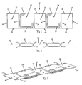
- a length of material 10 such as canvas, woven polyethylene, woven polypropylene, burlap, ballistic nylon, woven organic fibers or other material, formed into a single bag unit by folding over the material 10 lengthwise into two equal-sized lengths and dividing the folded material into substantially equal-sized, square sections 12, 14, 16, 18 and 20.
- Sections 14 and 18 are filled with sand, or another material, and sections 12, 16 and 20 are unfilled.
- the sections are divided and sealed along dotted lines 22, 24, 26, 28, 30, 32, 34, 36, 38, 40 and 42, by any method of sealing the sections apart, such as heat, sewing, clamping, stapling or adhesive.
- FIG. 3 shows the material 10 folded over into two equal lengthwise portions at edges 44,45.
- edges 24 and 34 are sealed by adhesive, as explained below, while the other sealed edges are sealed by sewing, clamping, stapling, or adhesive, as shown by the stitching.
- edges 24 and 34 could also be sealed by sewing. If the bags were made, filled and sealed in a manufacturing facility, edges 24 and 34 could easily be sealed by sewing. However, if the sections to be filled are not filled and sealed until they are used in the field, sewing would be highly impractical and sealing one edge 24, 34 of each bag in the field, by an adhesive, is much easier and faster than any of the other stated methods. Speed in filling, sealing and putting the bags in place, when they are filled in the field at the site of an emergency situation, is essential.
- the filled sections, 14 and 18, preferably have slanted sides, 54, 56, 58 and 60, and 62, 64, 66 and 68.
- the slanted sides of each filled section will fit together quite tightly, to provide a substantially water-tight structure.
- the angle of the slanted sides can vary from about 30 degrees to about 40 degrees, with 35 degrees being optimal. However, the exact angle is not crucial, because the bags are self-conforming.
- Fig. 4 shows the field-fillable bag unit shown in Figs. 1-3 , where the fillable sections have been filled with sand, or other material, and are ready to be sealed.
- the bag unit is divided into five sections, 12, 14, 16, 18 and 20, as shown in Figs. 1-3 .
- Sections 14 and 18 are fillable through open sides 24 and 34.
- Sides 24 and 24 are left unsealed, so that they can be filled in the field, or at any other location desired.
- a narrow strip of pressure sensitive adhesive 70 is applied to the inside surface of the two edges 72, 74 and 76, 78 of open sides 24 and 34. Over each of the narrow adhesive strips is placed a peel-off strip 80, 82, 84 and 86.
- peel-off strips 80, 82, 84 and 86 are peeled off by hand 88, Fig. 4 , exposing the pressure sensitive adhesive, the open edges of bag sections 14 and 18 are pressed together, Fig. 5 , and the bag is sealed.
- the pressure sensitive adhesive used is any adhesive with good adhesive power such as Chief # 290-HP Hot-Melt PSA, or 3MTM #350 High-Holding Acrylic PSA.
- the peel-off strips are preferably made from silicone-impregnated or polyethylen's-coated papers, or any other non-stick material.
- Fig. 4 depicts a person's hand 88 removing peel-off strips 80 and 82 from section 14, after it has been filled with sand, or other material.
- Fig. 5 depicts a person's hand 88 squeezing the two open edges 76 and 78 of section 18, sealing those edges, having a pressure sensitive adhesive, together.
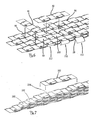
- Fig. 6 shows a plurality of bag units, including bag units 90, 92, 94, 96, 98, and 100 each having alternating sections of two filled sections and three unfilled and unfillable sections, in which the bag units are stacked in a transverse direction to provide a wide structure when that is desired.
- the bag units for example 92, are placed so that each filled section lays over an unfilled section, see bag unit 94.
- the bag units that are the outer edge of the stacked bag units will have an unfilled end section, such as section 110 of bag unit 100 and section 112 of bag unit 98, which are hanging out. These unfilled end sections may be left hanging or may be folded under the adjoining filled section, as seen in unfilled end section 113 of bag unit 99.
- Fig. 7 shows the more traditional stacking of bag units, including bag units 102, 104, 106 and 108 in a parallel direction.
- each filled section is alternately placed upon an unfilled section and each unfilled section is placed on a filled section. Due to the slanted four corners, such as 54, 56, 58, and 60 of each filled section, the bag units fit tightly together in a web connection, to provide a greater frictional coefficient and hence a stronger assemblage.
- the alternating sections of the bag units of this invention also provide a convenient way for men to carry the bags to a needed site, as they can be thrown over the shoulder, with the middle unfilled section upon the shoulder and two filled sections with the two unfilled end-flaps hanging down.
- the bags are shown with only two filled sections, since that is the easiest for a man to carry due to weight, however the bags could have more than two filled sections, depending upon their size and filled weight.
- the bags could also have a plurality of filled sections if they are to be carried and put in place by machine.
- interlocking bag units can be stacked, depending upon the size, height and length of the wall desired to be built.
- Sand is usually used to fill the bags, but other materials, such as earth, concrete, aggregate or particulate matter can be used.
- the bag units can be any size, however for manual use the optimum size of each section is from about 30.5 cm (one foot) square on each side to about 45.7 cm (18 inches) on each side.
- a 30.5 (one foot) square on each side bag section having two sections filled with sand and three unfilled sections, will weigh about 18.1 kg (40 pounds).
- a 45.7 cm (eighteen inch) square bag, having two sections filled with sand and three unfilled sections, will weigh about 36.3 kg (80 pounds).
- This adhesive is then covered with a protective-release-paper or 'peel-off-strip,' which prevents premature adhesion of the mating surfaces until needed, and helps to prevent contamination of the adhesive surface until time of use.
- a protective-release-paper or 'peel-off-strip which prevents premature adhesion of the mating surfaces until needed, and helps to prevent contamination of the adhesive surface until time of use.
- Other methods of closure of the sandbags such as zippers, hook & loop (Velcro) strips, interlocking-ribbed-plastic (Ziploc-type) stripes were also functional.
- the sandbags of this invention are usable in any situation where it is necessary to stop the flow of water, or any other liquid. In case of floods, rivers running over their banks, broken dams or broken water mains, or chemical fluid spills, it is often desired to built a sandbag wall to block and stop the flow of the liquid.
- the sandbags of this invention are also usable in any situation where it is necessary to create a barrier against the movement of dry earth, sand or any other material as a retaining wall.
- the sandbags of this invention are usable as well for many military applications, where it is necessary to protect against gunfire, explosive blasts, flying shrapnel, etc.
- these sandbags may also be fabricated from a wide variety of heavy-duty materials, such as but not limited to, ballistic nylon or woven organic fibers, such as KevlarTM to provide an even higher level of protection against penetration. While the bags herein are generically called “sandbags" they may actually be filled with a variety of filters including, but not limited to, earth, sand, concrete, aggregate, or particulate matter, or a combination of any of the above.
Landscapes
- Engineering & Computer Science (AREA)
- General Engineering & Computer Science (AREA)
- Environmental & Geological Engineering (AREA)
- Ocean & Marine Engineering (AREA)
- Mechanical Engineering (AREA)
- Civil Engineering (AREA)
- Structural Engineering (AREA)
- Revetment (AREA)
- Bag Frames (AREA)
Description
- The invention relates to bags used to provide a barrier. The barrier may prevent the passage of liquid, water, mud and silt during a flood or for other fluid flow problems. The barrier may also be used to protect against the collapse of dry sand or earth for below-grade retaining walls and trenching, or for the purpose of protection from gunfire explosive blasts and shrapnel, etc. in military applications.
- The invention described herein has improvements over the bag system described in our issued
U.S. Patent #6,428,240 . The improvements are discussed below. - Sandbags now in use are difficult to keep stacked, and they do not provide a stable structure when stacked or piled. Suggestions have been made to provide a method for stacking bags, such as in U.S. Patent #3,374,635 where rounded bags are tied together with lashing. However, as can be clearly seen, there are gaping spaces between the stacked bags, allowing considerable water to pass through the stacked bags.
- Another suggested method is shown in U.S. Patent #3,886,751 using complex shaped bags, which have a protuberance which fits into an indentation in an adjoining bag. This method is very inefficient because the protuberances do not maintain their integrity on site. The bags also require steel rods to hold open a second filler protuberance. These fillers can get easily clogged and the bags can get easily misshapen so that they do not fit together.
-
U.S. Patent #4,696,623 discloses an assembly for preventing erosion of a beach comprising a mat made from thermoplastic material with an open net weave. The mat has several compartments which are adjacent one another. Open net weave bags filled with ribbon thermoplastic material are inserted into the compartments and the assembly is attached to the shore. -
US 2004/0052584 A1 discloses a ballast system comprising an elongate member having a number of pouches, each pouch being capable of being opened and closed. The pouches can be filled with ballast material. - Applicants' invention comprises a length of material, such as canvas, woven polyethylene, woven polypropylene, burlap, ballistic nylon, woven organic fibers or other material, divided ino a unit having a series of two or more substantially equal sized sections. Every other section is fillable with particulate, such as sand, or other equivalent material, and every unit has an unfille and unfillable end-flap at both ends. When multiple sections are put in place, each row with an alternating filled section and an unfilled section, and stacked in layers, there is created a very secure, substantially water-tight structure. Because each section is substantially square, the sections can be stacked in a parallel or transverse direction, to effect a wider and stronger water-tight structure. The sections interlock to attain greater strength and water flow prevention. By having an unfilled and unfillable section at both ends of each unit, the bag units are reversible or bi-directional. That is, they may be stacked in any direction, parallel or transverse, in either direction, and no time needs to be spent in making sure they are stacked correctly.
- In addition, there is a great need for a field-fillable bag, that is, a bag that is not filled with sand, or other material, until it is used in the field. Applicants have provided an improved bag which is easily and quickly filable in the field and easily and quickly sealed after it has been filled.
- Accordingly, the present invention is defined by the appended claims.
-
-
Fig. 1 is a top plan view of the bag structure of this invention; -
Fig. 2 is a side elevational view ; -
Fig. 3 is a perspective view ; -
Fig. 4 is a perspective view of the field-fillable bags; -
Fig. 5 is a perspective view of the sealing of the bags; -
Fig. 6 is a perspective view of the transverse stacking of the bags; and -
Fig. 7 is a perspective view of the parallel stacking of the bags. - Referring now to the drawings, there is shown in
Figs. 1-3 a length ofmaterial 10, such as canvas, woven polyethylene, woven polypropylene, burlap, ballistic nylon, woven organic fibers or other material, formed into a single bag unit by folding over thematerial 10 lengthwise into two equal-sized lengths and dividing the folded material into substantially equal-sized,square sections Sections sections lines material 10 is folded over lengthwise, there is no need to seal the material atedges Fig. 3 shows thematerial 10 folded over into two equal lengthwise portions atedges - While using a single piece of material and folding it over to form the bag units is the easiest and most secure method of forming the bag units, it is also possible to use two separate pieces of material and attach them together by any of the aforementioned methods, such as sewing.
- As shown in
Figs. 1-3 ,edges edges edges edge - The filled sections, 14 and 18, preferably have slanted sides, 54, 56, 58 and 60, and 62, 64, 66 and 68. As can be seen in
Figs. 6 and 7 , the slanted sides of each filled section will fit together quite tightly, to provide a substantially water-tight structure. The angle of the slanted sides can vary from about 30 degrees to about 40 degrees, with 35 degrees being optimal. However, the exact angle is not crucial, because the bags are self-conforming. -
Fig. 4 shows the field-fillable bag unit shown inFigs. 1-3 , where the fillable sections have been filled with sand, or other material, and are ready to be sealed. The bag unit is divided into five sections, 12, 14, 16, 18 and 20, as shown inFigs. 1-3 .Sections open sides Sides sensitive adhesive 70 is applied to the inside surface of the twoedges open sides strip open bags strips hand 88,Fig. 4 , exposing the pressure sensitive adhesive, the open edges ofbag sections Fig. 5 , and the bag is sealed. The pressure sensitive adhesive used is any adhesive with good adhesive power such as Chief # 290-HP Hot-Melt PSA, or 3M™ #350 High-Holding Acrylic PSA. The peel-off strips are preferably made from silicone-impregnated or polyethylen's-coated papers, or any other non-stick material. -
Fig. 4 . depicts a person'shand 88 removing peel-offstrips section 14, after it has been filled with sand, or other material.Fig. 5 depicts a person'shand 88 squeezing the twoopen edges section 18, sealing those edges, having a pressure sensitive adhesive, together. -
Fig. 6 shows a plurality of bag units, includingbag units - The bag units, for example 92, are placed so that each filled section lays over an unfilled section, see
bag unit 94. The bag units that are the outer edge of the stacked bag units will have an unfilled end section, such assection 110 ofbag unit 100 andsection 112 ofbag unit 98, which are hanging out. These unfilled end sections may be left hanging or may be folded under the adjoining filled section, as seen inunfilled end section 113 ofbag unit 99. -
Fig. 7 shows the more traditional stacking of bag units, includingbag units - The alternating sections of the bag units of this invention also provide a convenient way for men to carry the bags to a needed site, as they can be thrown over the shoulder, with the middle unfilled section upon the shoulder and two filled sections with the two unfilled end-flaps hanging down. The bags are shown with only two filled sections, since that is the easiest for a man to carry due to weight, however the bags could have more than two filled sections, depending upon their size and filled weight. The bags could also have a plurality of filled sections if they are to be carried and put in place by machine.
- Any number of interlocking bag units can be stacked, depending upon the size, height and length of the wall desired to be built. Sand is usually used to fill the bags, but other materials, such as earth, concrete, aggregate or particulate matter can be used. The bag units can be any size, however for manual use the optimum size of each section is from about 30.5 cm (one foot) square on each side to about 45.7 cm (18 inches) on each side. A 30.5 (one foot) square on each side bag section having two sections filled with sand and three unfilled sections, will weigh about 18.1 kg (40 pounds). A 45.7 cm (eighteen inch) square bag, having two sections filled with sand and three unfilled sections, will weigh about 36.3 kg (80 pounds).
- After careful field studies using prototypes with a single end-flap, it was determined that there were limitations with regard to stacking possibilities and arrangements when only a single end-flap was available. With the addition of an extra end-flap, the bags became 'reversible' or 'bi-directional' rather than 'uni-directional', with increased variations possible with regard to stacking arrangements. Considerably less time was spent in the actual arranging or stacking of these modified sandbags, as less thought or consideration was needed regarding the position and placement of each unit.
- It was also determined that the increase in square centimetres (square inches) of available interlocking-surface-area (the extra end flap) directly increased the overall strength of the final, assembled structures which were constructed using this modification.
- This modification (the extra end flap) still allows for automated methods to be used to manuaactare, form, fill and seal the product, however there is a great need for a 'field-fillable' sandbag, one which may be filled and sealed on-site, wherever sandbags may be needed. Tests showed that the least complicated and most satisfactory method for sealing sandbags in the field, was accomplished by applying a 'pressure-sensitive-adhesive' or 'PSA' to both, opposing surfaces along the opening of each filable section or 'pouch'. This adhesive is then covered with a protective-release-paper or 'peel-off-strip,' which prevents premature adhesion of the mating surfaces until needed, and helps to prevent contamination of the adhesive surface until time of use. Other methods of closure of the sandbags, such as zippers, hook & loop (Velcro) strips, interlocking-ribbed-plastic (Ziploc-type) stripes were also functional.
- The sandbags of this invention are usable in any situation where it is necessary to stop the flow of water, or any other liquid. In case of floods, rivers running over their banks, broken dams or broken water mains, or chemical fluid spills, it is often desired to built a sandbag wall to block and stop the flow of the liquid. The sandbags of this invention are also usable in any situation where it is necessary to create a barrier against the movement of dry earth, sand or any other material as a retaining wall. The sandbags of this invention are usable as well for many military applications, where it is necessary to protect against gunfire, explosive blasts, flying shrapnel, etc. For such military purposes, these sandbags may also be fabricated from a wide variety of heavy-duty materials, such as but not limited to, ballistic nylon or woven organic fibers, such as Kevlar™ to provide an even higher level of protection against penetration. While the bags herein are generically called "sandbags" they may actually be filled with a variety of filters including, but not limited to, earth, sand, concrete, aggregate, or particulate matter, or a combination of any of the above.
Claims (17)
- A bag (10) adapted to be filled in the field and stacked in layers to provide a barrier comprising, a length of material having a plurality of alternating sections (12, 14, 16, 18, 20), wherein one section (14, 18) is fillable with a particulate material and the adjoining section (12, 16, 20) is unfilled and unfillable and each section to be filled has an open side (24, 34) with means (70) to seal the opening after it has been filled,
characterised in that each unfilled and unfillable section (12, 16, 20) is sealed (22, 26, 44, 46; 30, 32, 36, 48; 40, 42, 50, 52) and wherein there is an unfilled and unfillable section (12, 20) at both ends of the bag. - The bag of Claim 1 in which in its use position the stacked layers of bags provide a barrier against the flow of liquids, water, earth, mud, silt, explosive blasts, gunfire or shrapnel.
- The bag of Claim 1 or Claim 2 in which the fillable sections are fillable with sand, earth, concrete, aggregate, or particulate matter.
- The bag of any of Claims 1 to 3 in which each bag has two fillable sections (14, 18) and three sealed unfilled and unfillable sections (12 16, 20).
- The bag of Claim 1 in which the material is woven polyethylene, woven polypropylene, burlap, canvas, ballistic nylon or woven organic fibers.
- The bag of any of Claims 1 to 5 in which each fillable section has four slanted sides (54, 56, 58, 60; 62, 64, 66, 68).
- The bag of Claim 6 in which the sides are slanted at an angle of from about 30 degrees to about 40 degrees.
- The bag of any of Claims 1 to 7 in which the means to seal the fillable sections comprises an adhesive (70) on the inner edges of each open side.
- The bag of Claim 8 in which the adhesive has a peel-off strip (80, 82, 84, 86) covering the adhesive.
- The bag of any of Claims 1 to 9 in which each fillable section is filled and sealed.
- A method for forming a sandbag structure in the field characterised by transporting a plurality of sandbags according to claim 1 to the field, each sandbag (10) comprising a length of material having alternating sections (12, 14, 16, 18, 20), wherein one section (14, 18) is open with means (70) to seal the opening and the next adjoining section (12, 16, 20) is sealed (22, 26, 44, 46; 30, 32, 36, 48; 40, 42, 50, 52), unfilled and unfillable, with sealed unfilled and unfillable sections (12, 20) at both ends of each sandbag, filling each open section with sand, sealing it and stacking the sandbag in layers.
- The method of forming a sandbag structure of Claim 11 in which each bag has two filled sections and three sealed unfilled sections.
- The method of forming a sandbag structure of Claim 11 or 12 in which the material is woven polyethylene, woven polypropylene, burlap, canvas, ballistic nylon or woven organic fibers.
- The method of forming a sandbag structure of any of Claims 11 to 13 in which each filled section has four slanted sides (54, 56, 58, 60; 62, 64, 66, 68).
- The method of forming a sandbag structure of Claim 14 in which the sides are slanted at an angle of from about thirty to about forty degrees.
- The method of forming a sandbag structure of any of Claims 11 to 15 comprising stacking the sandbags in a parallel direction.
- The method for forming a sandbag structure of any of Claims 11 to 15 comprising stacking the sandbags in both a parallel and a transverse direction.
Applications Claiming Priority (1)
| Application Number | Priority Date | Filing Date | Title |
|---|---|---|---|
| PCT/US2003/021770 WO2005005807A1 (en) | 2003-07-11 | 2003-07-11 | Sectional interlocking barrier bags |
Publications (3)
| Publication Number | Publication Date |
|---|---|
| EP1644623A1 EP1644623A1 (en) | 2006-04-12 |
| EP1644623A4 EP1644623A4 (en) | 2008-05-21 |
| EP1644623B1 true EP1644623B1 (en) | 2013-04-10 |
Family
ID=34061435
Family Applications (1)
| Application Number | Title | Priority Date | Filing Date |
|---|---|---|---|
| EP03817462.9A Expired - Lifetime EP1644623B1 (en) | 2003-07-11 | 2003-07-11 | Sectional interlocking barrier bags and method of installation |
Country Status (8)
| Country | Link |
|---|---|
| US (1) | US7329069B2 (en) |
| EP (1) | EP1644623B1 (en) |
| JP (1) | JP2006527315A (en) |
| CN (1) | CN100406695C (en) |
| AU (1) | AU2003256501B2 (en) |
| CA (1) | CA2532157C (en) |
| MX (1) | MXPA06000250A (en) |
| WO (1) | WO2005005807A1 (en) |
Families Citing this family (38)
| Publication number | Priority date | Publication date | Assignee | Title |
|---|---|---|---|---|
| CA2496115A1 (en) * | 2005-02-08 | 2006-08-08 | Deltalok Inc. | Sandbag wall system with sandbags having a waist portion |
| GB2435651B (en) * | 2006-09-28 | 2009-12-02 | John William Farley | Manually foldable water permeable receptacle |
| WO2008037990A1 (en) * | 2006-09-28 | 2008-04-03 | John William Farley | Manually foldable receptacles |
| EP2397811B1 (en) * | 2007-01-19 | 2017-01-04 | Environmental Defence Systems Limited | Defence system |
| IT1396466B1 (en) * | 2008-07-11 | 2012-12-14 | Ing Sarti Giuseppe & C - Impresa Costr - Societa' Per Azioni | PROCEDURE FOR THE REALIZATION OF MANUFACTURED PRODUCTS AT LEAST PARTIALLY SUBMERGED AND MANUFACTURED ITEMS ACCORDING TO THIS PROCEDURE |
| US9809369B2 (en) | 2009-04-01 | 2017-11-07 | Scott E. Andochick | Method and apparatus for material storage, transport and dispensation |
| US9463914B2 (en) * | 2009-04-01 | 2016-10-11 | Scott E. Andochick | Method and apparatus for material storage and transport |
| US8672544B2 (en) | 2009-04-01 | 2014-03-18 | Scott E. Andochick | Method and apparatus for water storage and transport |
| USD787949S1 (en) | 2009-04-01 | 2017-05-30 | Scott E. Andochick | Water bag |
| US9637886B2 (en) * | 2009-06-22 | 2017-05-02 | R & J East, Inc. | Methods for controlling weeds and water using a bag filled with landscaping material |
| US9445552B2 (en) | 2009-06-22 | 2016-09-20 | R & J East, Inc. | Weed suppression system and method |
| US20110042531A1 (en) * | 2009-08-21 | 2011-02-24 | Karl Eric Hughes | Bi-pod/tri-pod stabilizing weight |
| US20110297575A1 (en) * | 2010-06-02 | 2011-12-08 | Clarence A. Cassidy | Water Barrier and Erosion Mitigation System |
| US20110299931A1 (en) * | 2010-06-02 | 2011-12-08 | Schaus David John | Containment Boom |
| NL2004901C2 (en) * | 2010-06-16 | 2011-12-19 | Marlon Roger Philipp Kratz | METHOD FOR BUILDING A BUILDING CONSTRUCTION WITH CONSTRUCTION ELEMENTS AND A SYSTEM OF CONSTRUCTION ELEMENTS THEREFORE. |
| US20120009019A1 (en) * | 2010-07-07 | 2012-01-12 | Breedlove John J | Spillway liner and method |
| WO2012125823A2 (en) * | 2011-03-15 | 2012-09-20 | Board Of Supervisors Of Louisiana State University And Agricultural And Mechanical College | Device for coastal restoration |
| US9297134B1 (en) | 2012-02-08 | 2016-03-29 | Carol J. Dancer | Self-expanding barrier for control of surface water flow |
| US9920500B2 (en) * | 2012-10-25 | 2018-03-20 | Seabed Technologies Llc | Apparatus and method for mat installation |
| US9926684B2 (en) | 2013-08-05 | 2018-03-27 | R & J East, Inc. | Roof runoff water control system |
| US9528237B2 (en) | 2014-03-19 | 2016-12-27 | Stewart Kriegstein | Structure including interlocking containers |
| GB2527401B (en) | 2014-04-08 | 2017-05-10 | Env Defence Systems Ltd | A method and apparatus for controlling a hazardous device |
| JP2017516934A (en) * | 2014-04-09 | 2017-06-22 | レビツェ インベスト, エス.アール.オー.Levice Invest, S.R.O. | Self-filling flood protection bag |
| JP6504553B2 (en) * | 2014-09-18 | 2019-04-24 | 松本 紘一 | Divisional storage type bag |
| US20160326700A1 (en) * | 2015-05-08 | 2016-11-10 | Elijah Ochoa | Ecologically friendly traction mat |
| US10000931B1 (en) * | 2016-12-13 | 2018-06-19 | Daniel T. Daugherty | Apparatus and method for moss remediation |
| CA2977936C (en) * | 2017-09-01 | 2024-02-27 | Glen Jewell | Weighted safety delineator anchor |
| CN108193699A (en) * | 2017-12-29 | 2018-06-22 | 中交天航港湾建设工程有限公司 | Construction method based on silt coast intertidal zone filling sack cofferdam Fast Filling |
| CN108275356A (en) * | 2018-03-29 | 2018-07-13 | 合肥振鑫塑料编织包装有限公司 | A kind of high intensity flood control woven bag |
| CN109235679B (en) * | 2018-08-30 | 2021-01-08 | 公安部四川消防研究所 | Fireproof and explosion-proof pressure reducing plate |
| USD913527S1 (en) * | 2018-10-17 | 2021-03-16 | Synthetex, Llc | Envelope for constructing a mat of spaced blocks |
| USD914245S1 (en) * | 2018-10-17 | 2021-03-23 | Synthetex, Llc | Erosion control mat |
| USD901721S1 (en) * | 2018-10-17 | 2020-11-10 | Synthetex, Llc | Block for an erosion control mat |
| DE102020110307B4 (en) | 2020-04-15 | 2022-02-24 | Naue Gmbh & Co. Kg | Geotextile sand container with quick release |
| US20240159049A1 (en) * | 2021-01-25 | 2024-05-16 | Earthbuilt Technology Pty Ltd | Building modules and techniques to make them |
| CN113981887B (en) * | 2021-10-19 | 2023-04-07 | 王玮 | Hydraulic engineering flood prevention sand bag |
| CN114108545B (en) * | 2021-12-01 | 2023-08-08 | 重庆艺锦陶瓷有限公司 | Segmented bundled piping emergency plugging machine |
| CN117802941A (en) * | 2023-12-20 | 2024-04-02 | 上海勘测设计研究院有限公司 | Filled ballast geomembrane structure and construction method |
Family Cites Families (23)
| Publication number | Priority date | Publication date | Assignee | Title |
|---|---|---|---|---|
| US3396542A (en) | 1965-10-05 | 1968-08-13 | Tech Inc Const | Method and arrangements for protecting shorelines |
| US3374635A (en) * | 1966-06-29 | 1968-03-26 | Horace C. Crandall | Bags for use in revetment structures |
| US3474626A (en) | 1967-08-24 | 1969-10-28 | Tech Inc Const | Method and means for protecting beaches |
| GB1208205A (en) | 1967-10-13 | 1970-10-07 | Toray Industries | Textile lining structure for use as revetment |
| DE1784360A1 (en) | 1968-07-30 | 1971-10-07 | Hoechst Ag | Fabric mat |
| US3957098A (en) | 1972-06-26 | 1976-05-18 | George Hepworth | Erosion control bag |
| US3886751A (en) | 1973-11-12 | 1975-06-03 | Jimenez Labora Mauricio Porraz | Aquatic construction module and method of forming thereof |
| JPS5314907A (en) | 1976-07-27 | 1978-02-10 | Yasunaga Riken Co Ltd | Woven cloth inclined scrib work |
| US4184788A (en) * | 1976-10-18 | 1980-01-22 | Raymond International, Inc. | Form for erosion control structures |
| US4102137A (en) | 1976-12-06 | 1978-07-25 | Mauricio Porraz | Coating and protective device |
| US4362433A (en) | 1980-10-30 | 1982-12-07 | Wagner David R | Flood disaster control bag |
| US4449847A (en) | 1982-09-27 | 1984-05-22 | Nicolon Corporation | Revetment panel |
| US4690585A (en) * | 1985-01-17 | 1987-09-01 | Holmberg Dick L | Erosion control foundation mat and method |
| US4981392A (en) * | 1989-06-29 | 1991-01-01 | Taylor Geoffrey L | Water inflatable structural module |
| SE9500795L (en) | 1995-03-03 | 1996-07-01 | Sigurd Melin | Liquid-damping protection wall and method and damper device for the construction of such protection wall |
| US5669732A (en) | 1995-06-19 | 1997-09-23 | Truitt; Willie W. | Self-closing interlocking sandbags and process for erecting dams therefrom |
| US5971661A (en) | 1997-07-30 | 1999-10-26 | Johnson; Harold Wayne | Water containment device and levee for impeding a flow of water |
| CN1163653C (en) * | 1999-02-05 | 2004-08-25 | 黄启光 | Bag linking method for quickly blocking burst of dam or dyke and steel pins |
| US6126362A (en) | 1999-03-01 | 2000-10-03 | Carter; Timothy L. | Pressure secured liquid damming protective bank device and method |
| US20020081153A1 (en) * | 2000-12-26 | 2002-06-27 | Genzel Bennett Ralph | Apparatus and method for flood control |
| US6428240B1 (en) * | 2001-02-02 | 2002-08-06 | Peter D. Ehrlich | Sectional interlocking sandbags |
| US6619884B2 (en) * | 2001-05-04 | 2003-09-16 | Beaver Bags, Inc. | Barrier device and method for building barrier wall |
| US7029205B2 (en) * | 2002-11-21 | 2006-04-18 | Daigle Richard A | Apparatus for pipeline stabilization and shoreline erosion protection |
-
2003
- 2003-07-11 MX MXPA06000250A patent/MXPA06000250A/en active IP Right Grant
- 2003-07-11 JP JP2005503942A patent/JP2006527315A/en active Pending
- 2003-07-11 CN CNB03826899XA patent/CN100406695C/en not_active Expired - Fee Related
- 2003-07-11 WO PCT/US2003/021770 patent/WO2005005807A1/en not_active Ceased
- 2003-07-11 CA CA2532157A patent/CA2532157C/en not_active Expired - Fee Related
- 2003-07-11 US US10/564,171 patent/US7329069B2/en not_active Expired - Fee Related
- 2003-07-11 AU AU2003256501A patent/AU2003256501B2/en not_active Ceased
- 2003-07-11 EP EP03817462.9A patent/EP1644623B1/en not_active Expired - Lifetime
Also Published As
| Publication number | Publication date |
|---|---|
| EP1644623A1 (en) | 2006-04-12 |
| WO2005005807A8 (en) | 2006-03-09 |
| CA2532157A1 (en) | 2005-01-20 |
| AU2003256501B2 (en) | 2010-09-09 |
| AU2003256501A1 (en) | 2005-01-28 |
| EP1644623A4 (en) | 2008-05-21 |
| JP2006527315A (en) | 2006-11-30 |
| US20060210360A1 (en) | 2006-09-21 |
| CN100406695C (en) | 2008-07-30 |
| WO2005005807A1 (en) | 2005-01-20 |
| CA2532157C (en) | 2012-12-11 |
| CN1820132A (en) | 2006-08-16 |
| MXPA06000250A (en) | 2006-07-03 |
| US7329069B2 (en) | 2008-02-12 |
| HK1094597A1 (en) | 2007-04-04 |
Similar Documents
| Publication | Publication Date | Title |
|---|---|---|
| CA2532157C (en) | Sectional interlocking barrier bags | |
| US20090274519A1 (en) | Flood control device and method of using same | |
| US7922421B2 (en) | Shoreline erosion and flood control system and method | |
| US6491431B2 (en) | Sandbag envelope | |
| CA2229525C (en) | Liquid containment/diversion dike | |
| US3696623A (en) | Woven mat | |
| AU769811B2 (en) | A rapid emergency dam | |
| US8382400B2 (en) | Sandbag | |
| US6428240B1 (en) | Sectional interlocking sandbags | |
| US10036134B2 (en) | Portable water inflatable barrier with interconnectable modules | |
| US20020119011A1 (en) | Fluent material confinement system | |
| BR112017016512B1 (en) | EQUIPMENT FOR CONTAINING A FLUID WITHIN A CONTAINMENT AREA AND METHOD FOR CONTAINING A FLUID WITHIN A CONTAINMENT AREA | |
| US20180305882A1 (en) | Portable water inflatable barrier with interconnectable modules | |
| MXPA06000186A (en) | A method and device for separation of a fluid, in particular oil, gas and water. | |
| US20120207545A1 (en) | Rapid Deployment, Self-Inflating, Interlocking, Modular Flood-Water Barrier Wall System | |
| US3890802A (en) | Reinforced dike | |
| US20150368868A1 (en) | Fluid-Fillable Barrier | |
| JPWO2005064086A1 (en) | Sandbag and waterproof bank | |
| TW200938700A (en) | Erosion-control structures made with attached sandbags | |
| CN101573496B (en) | cell reinforcement system | |
| JPH034686B2 (en) | ||
| HK1094597B (en) | Sectional interlocking barrier bags | |
| US11180897B2 (en) | Rigid retaining bag | |
| JPH0782718A (en) | Bag to be filled with heavy substance or environmental purification material | |
| JP6594154B2 (en) | Stacked sandbag structure |
Legal Events
| Date | Code | Title | Description |
|---|---|---|---|
| PUAI | Public reference made under article 153(3) epc to a published international application that has entered the european phase |
Free format text: ORIGINAL CODE: 0009012 |
|
| 17P | Request for examination filed |
Effective date: 20060111 |
|
| AK | Designated contracting states |
Kind code of ref document: A1 Designated state(s): AT BE BG CH CY CZ DE DK EE ES FI FR GB GR HU IE IT LI LU MC NL PT RO SE SI SK TR |
|
| DAX | Request for extension of the european patent (deleted) | ||
| A4 | Supplementary search report drawn up and despatched |
Effective date: 20080421 |
|
| 17Q | First examination report despatched |
Effective date: 20100212 |
|
| REG | Reference to a national code |
Ref country code: DE Ref legal event code: R079 Ref document number: 60343773 Country of ref document: DE Free format text: PREVIOUS MAIN CLASS: F02B0007080000 Ipc: E02B0003100000 |
|
| GRAP | Despatch of communication of intention to grant a patent |
Free format text: ORIGINAL CODE: EPIDOSNIGR1 |
|
| RIC1 | Information provided on ipc code assigned before grant |
Ipc: E02B 3/10 20060101AFI20120820BHEP |
|
| GRAS | Grant fee paid |
Free format text: ORIGINAL CODE: EPIDOSNIGR3 |
|
| GRAA | (expected) grant |
Free format text: ORIGINAL CODE: 0009210 |
|
| AK | Designated contracting states |
Kind code of ref document: B1 Designated state(s): AT BE BG CH CY CZ DE DK EE ES FI FR GB GR HU IE IT LI LU MC NL PT RO SE SI SK TR |
|
| REG | Reference to a national code |
Ref country code: GB Ref legal event code: FG4D |
|
| REG | Reference to a national code |
Ref country code: AT Ref legal event code: REF Ref document number: 606112 Country of ref document: AT Kind code of ref document: T Effective date: 20130415 Ref country code: CH Ref legal event code: EP |
|
| REG | Reference to a national code |
Ref country code: IE Ref legal event code: FG4D |
|
| REG | Reference to a national code |
Ref country code: DE Ref legal event code: R096 Ref document number: 60343773 Country of ref document: DE Effective date: 20130606 |
|
| PGFP | Annual fee paid to national office [announced via postgrant information from national office to epo] |
Ref country code: IE Payment date: 20130522 Year of fee payment: 11 Ref country code: GB Payment date: 20130523 Year of fee payment: 11 |
|
| PG25 | Lapsed in a contracting state [announced via postgrant information from national office to epo] |
Ref country code: SI Free format text: LAPSE BECAUSE OF FAILURE TO SUBMIT A TRANSLATION OF THE DESCRIPTION OR TO PAY THE FEE WITHIN THE PRESCRIBED TIME-LIMIT Effective date: 20130410 |
|
| REG | Reference to a national code |
Ref country code: AT Ref legal event code: MK05 Ref document number: 606112 Country of ref document: AT Kind code of ref document: T Effective date: 20130410 |
|
| REG | Reference to a national code |
Ref country code: NL Ref legal event code: VDEP Effective date: 20130410 |
|
| PG25 | Lapsed in a contracting state [announced via postgrant information from national office to epo] |
Ref country code: ES Free format text: LAPSE BECAUSE OF FAILURE TO SUBMIT A TRANSLATION OF THE DESCRIPTION OR TO PAY THE FEE WITHIN THE PRESCRIBED TIME-LIMIT Effective date: 20130721 Ref country code: NL Free format text: LAPSE BECAUSE OF FAILURE TO SUBMIT A TRANSLATION OF THE DESCRIPTION OR TO PAY THE FEE WITHIN THE PRESCRIBED TIME-LIMIT Effective date: 20130410 Ref country code: SE Free format text: LAPSE BECAUSE OF FAILURE TO SUBMIT A TRANSLATION OF THE DESCRIPTION OR TO PAY THE FEE WITHIN THE PRESCRIBED TIME-LIMIT Effective date: 20130410 Ref country code: AT Free format text: LAPSE BECAUSE OF FAILURE TO SUBMIT A TRANSLATION OF THE DESCRIPTION OR TO PAY THE FEE WITHIN THE PRESCRIBED TIME-LIMIT Effective date: 20130410 Ref country code: PT Free format text: LAPSE BECAUSE OF FAILURE TO SUBMIT A TRANSLATION OF THE DESCRIPTION OR TO PAY THE FEE WITHIN THE PRESCRIBED TIME-LIMIT Effective date: 20130812 Ref country code: BE Free format text: LAPSE BECAUSE OF FAILURE TO SUBMIT A TRANSLATION OF THE DESCRIPTION OR TO PAY THE FEE WITHIN THE PRESCRIBED TIME-LIMIT Effective date: 20130410 Ref country code: FI Free format text: LAPSE BECAUSE OF FAILURE TO SUBMIT A TRANSLATION OF THE DESCRIPTION OR TO PAY THE FEE WITHIN THE PRESCRIBED TIME-LIMIT Effective date: 20130410 Ref country code: GR Free format text: LAPSE BECAUSE OF FAILURE TO SUBMIT A TRANSLATION OF THE DESCRIPTION OR TO PAY THE FEE WITHIN THE PRESCRIBED TIME-LIMIT Effective date: 20130711 |
|
| PGFP | Annual fee paid to national office [announced via postgrant information from national office to epo] |
Ref country code: DE Payment date: 20130722 Year of fee payment: 11 |
|
| PG25 | Lapsed in a contracting state [announced via postgrant information from national office to epo] |
Ref country code: BG Free format text: LAPSE BECAUSE OF FAILURE TO SUBMIT A TRANSLATION OF THE DESCRIPTION OR TO PAY THE FEE WITHIN THE PRESCRIBED TIME-LIMIT Effective date: 20130710 Ref country code: CY Free format text: LAPSE BECAUSE OF FAILURE TO SUBMIT A TRANSLATION OF THE DESCRIPTION OR TO PAY THE FEE WITHIN THE PRESCRIBED TIME-LIMIT Effective date: 20130410 |
|
| PGFP | Annual fee paid to national office [announced via postgrant information from national office to epo] |
Ref country code: FR Payment date: 20130722 Year of fee payment: 11 |
|
| PG25 | Lapsed in a contracting state [announced via postgrant information from national office to epo] |
Ref country code: CZ Free format text: LAPSE BECAUSE OF FAILURE TO SUBMIT A TRANSLATION OF THE DESCRIPTION OR TO PAY THE FEE WITHIN THE PRESCRIBED TIME-LIMIT Effective date: 20130410 Ref country code: SK Free format text: LAPSE BECAUSE OF FAILURE TO SUBMIT A TRANSLATION OF THE DESCRIPTION OR TO PAY THE FEE WITHIN THE PRESCRIBED TIME-LIMIT Effective date: 20130410 Ref country code: DK Free format text: LAPSE BECAUSE OF FAILURE TO SUBMIT A TRANSLATION OF THE DESCRIPTION OR TO PAY THE FEE WITHIN THE PRESCRIBED TIME-LIMIT Effective date: 20130410 Ref country code: EE Free format text: LAPSE BECAUSE OF FAILURE TO SUBMIT A TRANSLATION OF THE DESCRIPTION OR TO PAY THE FEE WITHIN THE PRESCRIBED TIME-LIMIT Effective date: 20130410 |
|
| PLBE | No opposition filed within time limit |
Free format text: ORIGINAL CODE: 0009261 |
|
| STAA | Information on the status of an ep patent application or granted ep patent |
Free format text: STATUS: NO OPPOSITION FILED WITHIN TIME LIMIT |
|
| PG25 | Lapsed in a contracting state [announced via postgrant information from national office to epo] |
Ref country code: RO Free format text: LAPSE BECAUSE OF FAILURE TO SUBMIT A TRANSLATION OF THE DESCRIPTION OR TO PAY THE FEE WITHIN THE PRESCRIBED TIME-LIMIT Effective date: 20130410 Ref country code: MC Free format text: LAPSE BECAUSE OF FAILURE TO SUBMIT A TRANSLATION OF THE DESCRIPTION OR TO PAY THE FEE WITHIN THE PRESCRIBED TIME-LIMIT Effective date: 20130410 Ref country code: IT Free format text: LAPSE BECAUSE OF FAILURE TO SUBMIT A TRANSLATION OF THE DESCRIPTION OR TO PAY THE FEE WITHIN THE PRESCRIBED TIME-LIMIT Effective date: 20130410 |
|
| REG | Reference to a national code |
Ref country code: CH Ref legal event code: PL |
|
| 26N | No opposition filed |
Effective date: 20140113 |
|
| REG | Reference to a national code |
Ref country code: DE Ref legal event code: R097 Ref document number: 60343773 Country of ref document: DE Effective date: 20140113 |
|
| PG25 | Lapsed in a contracting state [announced via postgrant information from national office to epo] |
Ref country code: CH Free format text: LAPSE BECAUSE OF NON-PAYMENT OF DUE FEES Effective date: 20130731 Ref country code: LI Free format text: LAPSE BECAUSE OF NON-PAYMENT OF DUE FEES Effective date: 20130731 |
|
| REG | Reference to a national code |
Ref country code: DE Ref legal event code: R119 Ref document number: 60343773 Country of ref document: DE |
|
| GBPC | Gb: european patent ceased through non-payment of renewal fee |
Effective date: 20140711 |
|
| REG | Reference to a national code |
Ref country code: IE Ref legal event code: MM4A |
|
| REG | Reference to a national code |
Ref country code: FR Ref legal event code: ST Effective date: 20150331 |
|
| PG25 | Lapsed in a contracting state [announced via postgrant information from national office to epo] |
Ref country code: DE Free format text: LAPSE BECAUSE OF NON-PAYMENT OF DUE FEES Effective date: 20150203 |
|
| REG | Reference to a national code |
Ref country code: DE Ref legal event code: R119 Ref document number: 60343773 Country of ref document: DE Effective date: 20150203 |
|
| PG25 | Lapsed in a contracting state [announced via postgrant information from national office to epo] |
Ref country code: FR Free format text: LAPSE BECAUSE OF NON-PAYMENT OF DUE FEES Effective date: 20140731 Ref country code: GB Free format text: LAPSE BECAUSE OF NON-PAYMENT OF DUE FEES Effective date: 20140711 |
|
| PG25 | Lapsed in a contracting state [announced via postgrant information from national office to epo] |
Ref country code: TR Free format text: LAPSE BECAUSE OF FAILURE TO SUBMIT A TRANSLATION OF THE DESCRIPTION OR TO PAY THE FEE WITHIN THE PRESCRIBED TIME-LIMIT Effective date: 20130410 |
|
| PG25 | Lapsed in a contracting state [announced via postgrant information from national office to epo] |
Ref country code: HU Free format text: LAPSE BECAUSE OF FAILURE TO SUBMIT A TRANSLATION OF THE DESCRIPTION OR TO PAY THE FEE WITHIN THE PRESCRIBED TIME-LIMIT; INVALID AB INITIO Effective date: 20030711 Ref country code: LU Free format text: LAPSE BECAUSE OF NON-PAYMENT OF DUE FEES Effective date: 20130711 |
|
| PG25 | Lapsed in a contracting state [announced via postgrant information from national office to epo] |
Ref country code: IE Free format text: LAPSE BECAUSE OF NON-PAYMENT OF DUE FEES Effective date: 20140711 |