EP1643919B1 - Device for fragmenting substances - Google Patents
Device for fragmenting substances Download PDFInfo
- Publication number
- EP1643919B1 EP1643919B1 EP04740885A EP04740885A EP1643919B1 EP 1643919 B1 EP1643919 B1 EP 1643919B1 EP 04740885 A EP04740885 A EP 04740885A EP 04740885 A EP04740885 A EP 04740885A EP 1643919 B1 EP1643919 B1 EP 1643919B1
- Authority
- EP
- European Patent Office
- Prior art keywords
- shock
- transmitting element
- end position
- distal end
- housing
- Prior art date
- Legal status (The legal status is an assumption and is not a legal conclusion. Google has not performed a legal analysis and makes no representation as to the accuracy of the status listed.)
- Expired - Fee Related
Links
Images


Classifications
-
- A—HUMAN NECESSITIES
- A61—MEDICAL OR VETERINARY SCIENCE; HYGIENE
- A61B—DIAGNOSIS; SURGERY; IDENTIFICATION
- A61B17/00—Surgical instruments, devices or methods, e.g. tourniquets
- A61B17/22—Implements for squeezing-off ulcers or the like on the inside of inner organs of the body; Implements for scraping-out cavities of body organs, e.g. bones; Calculus removers; Calculus smashing apparatus; Apparatus for removing obstructions in blood vessels, not otherwise provided for
- A61B17/22004—Implements for squeezing-off ulcers or the like on the inside of inner organs of the body; Implements for scraping-out cavities of body organs, e.g. bones; Calculus removers; Calculus smashing apparatus; Apparatus for removing obstructions in blood vessels, not otherwise provided for using mechanical vibrations, e.g. ultrasonic shock waves
- A61B17/22012—Implements for squeezing-off ulcers or the like on the inside of inner organs of the body; Implements for scraping-out cavities of body organs, e.g. bones; Calculus removers; Calculus smashing apparatus; Apparatus for removing obstructions in blood vessels, not otherwise provided for using mechanical vibrations, e.g. ultrasonic shock waves in direct contact with, or very close to, the obstruction or concrement
- A61B17/22022—Implements for squeezing-off ulcers or the like on the inside of inner organs of the body; Implements for scraping-out cavities of body organs, e.g. bones; Calculus removers; Calculus smashing apparatus; Apparatus for removing obstructions in blood vessels, not otherwise provided for using mechanical vibrations, e.g. ultrasonic shock waves in direct contact with, or very close to, the obstruction or concrement using electric discharge
-
- A—HUMAN NECESSITIES
- A61—MEDICAL OR VETERINARY SCIENCE; HYGIENE
- A61B—DIAGNOSIS; SURGERY; IDENTIFICATION
- A61B17/00—Surgical instruments, devices or methods, e.g. tourniquets
- A61B17/56—Surgical instruments or methods for treatment of bones or joints; Devices specially adapted therefor
- A61B17/58—Surgical instruments or methods for treatment of bones or joints; Devices specially adapted therefor for osteosynthesis, e.g. bone plates, screws, setting implements or the like
- A61B17/88—Osteosynthesis instruments; Methods or means for implanting or extracting internal or external fixation devices
- A61B17/92—Impactors or extractors, e.g. for removing intramedullary devices
- A61B2017/922—Devices for impaction, impact element
Definitions
- the invention relates to a device for fragmenting substances, comprising a probe having an elongate probe shaft, at the distal end of which a probe head is arranged which has an electrohydraulic transducer which abruptly converts electrical energy supplied from proximally via the probe shaft into mechanical kinetic energy.
- the transducer comprises a housing in which a liquid chamber and a shock-transmitting designed as a piston Element is arranged, which is movable from a proximal end position in the longitudinal direction of the housing in a distal end position, wherein the distal end position is defined by a stop on the housing, against which a arranged on the shock-transmitting element counter stop runs, according to the preamble of claim 1.
- Such a device is off JP 61 217147 A known.
- Electrohydraulic lithotripsy for fragmentation of hard tissues and calculi, such as intracorporeal stones, such as kidney stones, Urethersteinen, bladder stones, gallstones, salivary stones, etc., bone, cartilage, lens material in the eye, bone cement, thrombi , Deposits and calcifications used.
- Such a device may also be used to stimulate tissue.
- EHL electrohydraulic lithotripsy
- a shock transmission element in the form of a piston, which can be moved axially in the housing from a proximal end position (rest position) into a distal end position.
- a current pulse to the two electrodes, cavitation bubbles are explosively formed in the conductive liquid in the liquid chamber via the electrical short circuit, resulting in a shock-like pressure wave which causes the shock-transmitting element to move abruptly distally from its proximal rest position, so that a distal end face of the shock-absorbing element Impact-transmitting element may impact the substance to be fragmented to smash them.
- the device known from the aforementioned document represents an improvement of conventional EHL probes in which no shock-transmitting element is provided, but in which the pressure wave produced by the explosive spark discharge at the electrodes is used for fragmentation.
- Such a device is for example off EP-A-0 640 316 known.
- the pressure waves which act not only axially, but in all directions, disadvantageously result in traumatization of soft tissue, for example by burns due to sparks during short-circuiting of the electrodes, as well as mechanical defects such as perforations.
- the shock-transmitting element of US-A-5 425 735 known EHL probe avoids this problem, since it axially channels the propagating in all directions pressure waves in the liquid chamber.
- the shock-transmitting element is moved by the explosion-propagating pressure waves (shock waves) from the proximal end position to the distal end position, wherein the distal end position is defined by a stop on the housing of the transducer, which is formed in the known device by a radial annular surface in the region of the distal end of the housing.
- a counter-stop is provided, which is formed in the form of a radial annular surface in the region of the proximal end of the shock-transmitting element.
- a compression spring is arranged, which is supported distally on the annular surface on the housing and on the proximal side on the annular surface on the impact-transmitting element.
- the compression spring is connected in the path of the counter-attack.
- the compression spring has the task to move the counter-stop from the distal end position back to the proximal end position.
- the shock-transmitting element performs only a partial stroke of its maximum travel between the proximal and distal end position, so that the shock-transmitting element runs against a "soft" stop. However, then it is not possible to optimally accelerate the shock-transmitting element and thereby transfer the kinetic energy of the shock-transmitting element as possible jerky and out of the maximum speed on the substance to be fragmented.
- the spring is set soft so that the shock transmitting member can run to the distal end stop, the spring must still be fully compressed, thereby dissipating some of the kinetic energy imparted to the shock transmitting member by the pressure wave, resulting in deceleration the shock-transmitting element leads. Even in this case, therefore, there is no optimal impulsive energy transfer to the substance to be fragmented.
- JP 61 217147 A provided that the shock-transmitting element is movable from a proximal end position in the longitudinal direction of the housing into a distal end position, wherein the distal end position is defined by a stop on the housing, against which a counter-stop arranged on the shock-transmitting element runs.
- the stop and the counter-stop are designed so that the counter-stop comes into direct contact with the stop during its movement from the proximal to the distal end position, and the push-transmitting element is moved back into the proximal end position substantially as a result of the impact on the stop.
- a fluid line leads into the fluid chamber of the electrohydraulic converter.
- the document US 5 103 556 A discloses an electro-hydraulic probe for use with a lithotriptoscope.
- the probe has two electrodes at the distal end, with a spacer made of dielectric material between the electrodes to prevent direct current flow between the first electrode and the second electrode.
- a device for crushing concrements in the medical field which has a probe whose distal end points in the direction of a calculus to be crushed and the proximal end is accommodated in a housing in a guide.
- This housing is thus arranged at the proximal end of the probe shaft, so that the shock wave generation is extracorporeal.
- the shock wave generation does not take place by means of an electro-hydraulic converter, but by means of an electromagnetic linear motor.
- the probe shaft has an impact surface on which a mass body accelerated in the electromagnetic field impinges, in order to introduce pulses into the probe, which are conducted via the probe in the direction of the concretion to be fragmented.
- the impact surface of the probe forms a predefined output state to a drive-side input of a probe guide located in a stop surface, into which the probe can be returned after each shock pulse.
- the invention has the object of developing a device of the type mentioned in such a way that the optimal function of the electro-hydraulic converter of the device is ensured.
- this object is achieved in terms of the device mentioned above in that the at least one feed line extends through the probe shaft.
- the device according to the invention is therefore provided to make the path of the counter-attack to stop free, i. not to switch a spring as in the known device in the direct path, so that the counter-stop of the device according to the invention comes directly into contact with the stop and thus not soft, but runs hard against the stop.
- a return mechanism for the shock-transmitting element of the device according to the invention therefore does not require the force of a spring against which the shock-transmitting element must move in its movement from the proximal to the distal end position and emits to this energy, but the shock-transmitting element is characterized in the proximal Moves back end position by the impact hit hard on the stop and thereby "reflected" on this.
- liquid chamber of the electro-hydraulic converter leads at least one supply line for a liquid.
- the at least one supply line runs through the probe shaft.
- the shock-transmitting element is held by means of a holding mechanism in the proximal end position of the shock-transmitting Element in its movement from the proximal to the distal end position substantially withdraws no kinetic energy.
- a holding mechanism for the shock-transmitting element in the proximal end position is provided in the device according to the invention, which advantageously ensures that the shock-transmitting element always begins its movement stroke from the proximal end position.
- this holding mechanism provided according to the invention is designed such that it substantially removes no kinetic energy from the shock-transmitting element, whereby the mechanical impact transmission is not impaired by the holding mechanism.
- the holding mechanism has a spring which is designed so that its maximum possible spring travel is greater than the path of the shock-transmitting element between the proximal and the distal end position.
- a spring is provided, but in the present case only has the task to keep the shock-transmitting element in the proximal end position.
- the spring is designed such that it substantially removes no kinetic energy from the proximal to the distal end position of the shock-transmitting element during its movement, because its maximum spring travel is greater than the travel of the shock-transmitting element.
- the maximum spring travel can be more than 1.2 times, preferably more than twice, the stroke of the shock-transmitting element.
- the spring is a compression spring whose length is greater than the path of the shock-transmitting element between the proximal and the distal end position.
- the length of the compression spring is equal to the maximum travel of the shock-transmitting element, which in the present invention has the advantage of substantially unrestrained movement of the shock-transmitting element between the proximal and distal end positions.
- the spring is arranged around a distal portion of the shock-transmitting element and is supported distally on the housing and on the proximal side on a shoulder on the shock-transmitting element, without lying in the path of the counter-attack.
- This arrangement of the spring is advantageous in contrast to the arrangement of the spring in the known device, in which the spring is arranged in the path between the counter-stop and the stop, because the counter-stop can thus bounce freely against the distal hard stop on the housing, whereby an optimal impulse transmission to the substance to be fragmented is made possible.
- the holding mechanism may preferably hold the shock-transmitting element by means of magnetic force in the proximal end position.
- the probe of the device according to the invention can be configured in its distal region with very small dimensions, which is advantageous for applications of the device for fragmentation of stones in the ureter ,
- the counter-stop is formed as a lateral projection which engages in a slot in the wall of the housing, whose distal end forms the housing-side stop.
- This construction is a structurally advantageous simple way to counter-stop and stop in such a way that the counter-stop runs freely against the stop on the housing and can be "reflected" on this.
- the scenery may, for example, be a recess in the wall of the housing.
- the link is delimited on the proximal side in order to define the proximal end position of the shock-transmitting element.
- the proximal end position of the shock-transmitting element is advantageously defined by the same backdrop at the same time, whereby the design effort is further reduced, because no further stop for the proximal end position in the form of a separate component is needed.
- the aforementioned backdrop may, for example, in the form of a slot which passes radially through the wall of the housing or formed as an inner recess in the housing wall, be realized.
- the abovementioned lateral projection is formed by a pin which extends transversely through the shock-transmitting element and which engages on opposite sides in a respective slot in the wall of the housing.
- the stroke of the shock-transmitting element between the proximal and the distal end position is in the range of about 0.2 to about 2 mm, preferably from about 0.4 to about 1.5 mm.
- This measure advantageously contributes to an improved transmission of the momentum-like kinetic energy of the shock-transmitting element to the substance to be fragmented because, due to the shortness of the movement path, a loss of kinetic energy in the movement from the proximal to the distal end position can be substantially avoided.
- the velocity of the shock-transmitting element is at least 2 m / s, preferably at least 5 m / s, more preferably at least 15 m / s and / or the repetition frequency of the movement of the shock-like element from the proximal to the distal end position is at least 2 Hz, preferably at least 15 Hz.
- At least one feed line into the liquid chamber is preferably formed by at least one opening in the wall of the housing of the converter, and / or at least one feed line is formed by at least one through opening in the shock-transmitting element.
- the provision of at least one supply line through at least one opening in the wall of the housing of the converter and / or by at least one through opening in the shock-transmitting element has the advantage that the probe itself can be configured very simply, because it dispenses with a supply line from the proximal can. For example, since endourological intracorporeal stone therapies always under liquid environment can be made, this liquid can then enter the body through the at least one opening in the wall of the housing or in the shock-transmitting element in the liquid chamber.
- the at least one feed line is formed by at least one opening in the wall of the housing of the transducer
- the at least one opening is preferably arranged distally on a portion of the shock-transmitting element which allows a passage of liquid into the liquid chamber, a passage of voltage sparks however prevented.
- the liquid can penetrate the housing on the distal side of the liquid chamber and penetrate into the liquid chamber, for example, by a certain play between the shock-transmitting element and the housing of the transducer.
- the spark of the electro-hydraulic converter from the housing of the transducer passes through the outside and can injure the patient.
- the probe shaft is flexible.
- the device according to the invention can also be introduced into non-straight passages, for example in urological treatments in the ureter.
- the probe head has a stiffening proximally, for example in the form of a metal tube.
- the probe head has a stiffening over its entire length.
- the probe head has a diameter of less than about 5 mm, preferably less than about 2 mm, preferably less than about 1.5 mm.
- the device according to the invention can also be used in very narrow body ducts for the fragmentation of substances or for the stimulation of tissue.
- the probe is integrated in a catheter.
- the catheter additionally has at least one lumen for the supply and / or removal of rinsing liquid, and / or additionally has a lumen for the passage of a miniaturized endoscope.
- an acoustic pickup is provided, which receives the acoustic signal of the ignition of the electro-hydraulic converter and the impact of the shock-transmitting element on the substance.
- the acoustic signal that receives the transducer can be used for differentiation, whether the shock-transmitting element has encountered a hard substance, such as a body stone, or on soft tissue. Namely, the impact of the shock transmitting member on a stone is acoustically distinguishable from a shock of the member against soft tissue.
- the acoustic transducer may be located at the proximal end of the probe shaft and / or on the body surface of a patient.
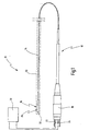
- Fig. 1 there is shown a device for fragmenting substances provided with the general reference numeral 10.
- the device 10 may be used for lithotripsy of urinary stones in the urinary bladder, urethra, kidney, or gallbladder stones.
- the device 10 can be used for lithotripsy of salivary stones.
- Further applications of the device 10 are the treatment of vascular occlusions in calcifications, thrombi or the stimulation or pressure wave therapy in orthopedics, for example for the treatment of tennis elbow.
- the device 10 can be used for ablation of bone cement or for ablation of the lens in the eye.
- the device 10 can also be used for technical purposes, for example for the removal of calcium deposits in piping systems.
- the device 10 has a probe 12 having an elongate probe shaft 14, which is flexible in the illustrated embodiment, and a probe head 16 at the distal end of the probe shaft 14.
- the probe 12 has a connection housing 18, via which the probe 12 can be connected to an electrical energy source 20.
- contacts 22 and 24 are provided at the proximal end of the connection housing 18, to which a cable connector (not shown in more detail) for connection to the electrical energy source 20 can be connected.
- a cable connector (not shown in more detail) for connection to the electrical energy source 20 can be connected.
- Starting from the contacts 22 and 24 extend through the probe shaft 14 each have thin flexible current-conducting wires, which are not shown in detail in the drawing. These wires lead to the probe head 16.
- an electro-hydraulic transducer 26 is arranged, which converts from proximal via the probe shaft 14 supplied electrical energy via a short circuit jerky into mechanical kinetic energy.
- the transducer 26 has a housing 28 in which a fluid chamber 30 filled with conductive liquid is arranged. Furthermore, a shock-transmitting element 32 is arranged in the housing 28.
- two electrodes 34 and 36 are immersed, which can be acted upon by the above-mentioned current-conducting wires in the probe shaft 14 with voltage pulses generated by the electrical energy source 20.
- the electrodes 34 and 36 with a current pulse form in the liquid in the liquid chamber 30 via the short explosive cavitation bubbles, which leads to an explosive pressure increase in the liquid chamber 30.
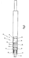
- the shock-transmitting element 32 is in the housing 28 of the electro-hydraulic converter 26 of a in Fig. 2 shown proximal end position in an in Fig. 3 shown distal end position in the longitudinal direction of the housing 28 movable, wherein this movement is caused by the explosive pressure increase in the liquid chamber 30 after the application of the electrodes 34 and 36 with a voltage pulse.
- the shock-transmitting member 32 has a proximal portion 38 having an outer periphery which corresponds approximately to the inner periphery of the housing 28 or has a slight clearance to this.
- a distal portion 40 of the shock transmitting member 32 connects, which has a smaller diameter than the proximal portion 38, and which can project through a distal end opening 42 from the housing 28 to the distal when the shock-transmitting element moved from the proximal end position to the distal end position.
- the distal end position of the shock-transmitting element 32 is defined by a hard stop 44 on the housing 28, against which a counter-stop 46 of the shock-transmitting element 32 arranged on the impact-transmitting element 32 runs, which is formed as a lateral projection on the element 32.
- the hard stop 44 on the housing 28 is formed by a distal end 48 of a link 50, the latter in the form of a
- a proximal end 52 of the link 50 defines the proximal end position of the shock transmitting member 32.
- the backdrop 50 diametrically opposite is a second gate 50 ', also in the form of an elongated hole, formed on the housing 28.
- the counter-abutment 46 of the shock-transmitting member 32 is formed in the form of a pin 54 which is inserted into a bore 56 in the proximal portion 38 of the otherwise formed as a solid body shock-transmitting element 32.
- the pin 54 projects beyond the proximal portion 38 of the shock-transmitting element 32 on both sides and engages in accordance with the slide 50 and the link 50 ', whereby the shock-transmitting element 32 in the gate 50 and 50' is guided.
- Fig. 2 and 3 shows, the path of the counter-stop 46 to the stopper 44 is free, so that the counter-stop 46 comes in the distal end position of the shock-transmitting element 32 with the stopper 44 directly and above all hard in contact.
- the shock-transmitting element 32 is jerky from his in Fig. 2 shown proximal end position in the in Fig. 3 shown distal end position moves where the counter-stop 46 hard against the Stop 44 runs and due to this impact, the shock-transmitting element 32 undergoes a fully elastic shock and from the in Fig. 3 shown end position again in the proximal end position according to Fig. 2 is "reflected back".
- Fig. 6 is shown to the movement of a path-time diagram, wherein the time t is plotted on the x-axis and the path s of the shock-transmitting element on the y-axis.
- the shock-transmitting element 32 is abruptly set in motion by igniting the electrodes 34 and 36 from the proximal end position s p and moves at high and, above all, constant speed, ie unbraked into the distal end position s d , as can be seen from FIG linear increase of the motion curve.
- a probe was used whose shock-transmitting element 32 has a defined stroke s p - s d of 0.85 mm, wherein a speed of the element 32 against the stop 44 of 11.8 m / s was measured.
- a holding mechanism 58 is provided in the housing 28 which is formed so that it in the movement of the shock-transmitting member 32 from the proximal end position in the distal end position substantially no kinetic energy of the shock-transmitting element 32 extracts.
- the holding mechanism 58 has a spring 60 which is formed so that its maximum spring travel is greater than the path of the shock-transmitting element 32 from the proximal to the distal end position.
- the spring 60 is formed as a compression spring whose length is greater than the stroke of the shock-transmitting element 32 between the proximal and the distal end position, i. the length of the spring 60 is greater than the length of the links 50 and 50 ', in which the counter-stop 46 is running.
- the spring 60 is disposed about the distal portion 40 of the shock transmitting member 32 and abuts distally on the housing 28 and proximally on a shoulder 61 between the distal portion 40 and the proximal portion 38 of the shock transmitting member 32.
- the spring 60 is not in the path of the counter-attack 46 to stop 44, whereby the shock-transmitting element 32 unrestrained against the hard stop 44 runs and can return by almost complete pulse reversal back to the proximal end position.
- the shock-transmitting element 32 can also be moved by means of magnetic force in the proximal end position according to FIG Fig. 2 being held. It may additionally be provided to provide a trigger mechanism for the magnetic force, which in synchronization with the ignition of the Electrodes 34 and 36, the magnetic holding force turns off and on after a period of time, which corresponds to the time required for the shock-transmitting element 32 from the proximal to the distal and from there back to the proximal end position.
- the stroke of the shock-transmitting element 32 between the proximal and the distal end position which is predetermined by the length of the link 50 or the link 50 ' is in the range of about 0.2 to 2 mm, preferably from about 0.4 to about 1.5 mm.
- the stroke of the shock-transmitting element 32 is thus very short.
- the speed of the shock-transmitting element 32 from the proximal to the distal end position is at least 2 m / s, preferably at least 5 m / s, more preferably at least 15 m / s.
- the repetition frequency of the movement of the shock-like element 32 from the proximal to the distal end position is at least 2 Hz, preferably at least 15 Hz, so that a sufficient repetition rate of the jerky movement of the shock-transmitting element 32 is achieved.
- the supply of liquid takes place in the liquid chamber 30 from the proximal side over the probe shaft 14.
- At least one supply line for a liquid leads into the liquid chamber 30 of the electrohydraulic converter 26, wherein in the exemplary embodiment shown several supply lines are formed by circumferentially distributed openings, of which FIG Fig. 4 four openings 62 to 68 can be seen, which are formed in the wall of the housing 28.
- the openings 66 and 68 are arranged distally of the proximal portion 38 of the shock-transmitting element 32, the openings 62 and 64 are located at a location which is still distal to the liquid chamber 30, so that upon ignition of the electrodes 34 and 36, a penetration of the Ignition spark is avoided out of the housing 28 out.
- the supply of liquid into the liquid chamber 30 can also be effected by bores in the impact-transmitting element 32.
- the liquid entering through the apertures 62-68 is directed into the fluid chamber 30 by having little lateral clearance between the proximal portion 38 of the shock transmitting member 32 and the housing 28 through which fluid can pass, but with sparks passing through avoids.
- bores may also be provided in the shock-transmitting element 32 for the purpose of conveying the fluid from distal to proximal into the fluid chamber 30.
- the probe head 16 in its proximal region a stiffening, for example in the form of a metal tube by the housing 28 of the electro-hydraulic converter 26 extends much further to the proximal than would be required due to the position of the electrodes 34 and 36.
- stiffening the probe head 16 in the proximal region ensures that the jerky Pulse at the ignition of the electrodes 34 and 36 distally, and not acting proximally.
- the probe 12 is integrated in a catheter 70 which is only indicated in the drawing and which has at least one lumen for the supply and / or removal of rinsing fluid and additionally a lumen for the passage of a miniaturized endoscope.
- the probe head is miniaturized and has a diameter of less than about 5 mm, preferably less than about 2 mm, more preferably less than about 1.5 mm, thereby enabling its integration into a catheter.
- an acoustic pickup may still be present, which is arranged for example in the connection housing 18 of the probe 12, and which receives the acoustic signal of the short circuit of the electrodes 34 and 36 and the impact of the shock-transmitting element 32 on the substance to be fragmented. Since the impact of the impact-transmitting element 32 on, for example, a body stone is different from the impact on soft tissue, the acoustic transducer allows differentiation with respect to the target substance to be treated.
Abstract
Description
Die Erfindung betrifft eine Vorrichtung zum Fragmentieren von Substanzen, mit einer Sonde, die einen langerstreckten Sondenschaft aufweist, an dessen distalem Ende ein Sondenkopf angeordnet ist, der einen elektrohydraulischen Wandler aufweist, der von proximal über den Sondenschaft zugeführte elektrische Energie stoßartig in mechanische Bewegungsenergie umwandelt, wobei der Wandler ein Gehäuse aufweist, in dem eine Flüssigkeitskammer und ein als Kolben ausgebildetes stoßübertragendes Element angeordnet ist, das aus einer proximalen Endstellung in Längsrichtung des Gehäuses in eine distale Endstellung bewegbar ist, wobei die distale Endstellung durch einen Anschlag am Gehäuse definiert ist, gegen den ein am stoßübertragenden Element angeordneter Gegenanschlag läuft, gemäß dem Oberbegriff des Anspruchs 1.The invention relates to a device for fragmenting substances, comprising a probe having an elongate probe shaft, at the distal end of which a probe head is arranged which has an electrohydraulic transducer which abruptly converts electrical energy supplied from proximally via the probe shaft into mechanical kinetic energy. wherein the transducer comprises a housing in which a liquid chamber and a shock-transmitting designed as a piston Element is arranged, which is movable from a proximal end position in the longitudinal direction of the housing in a distal end position, wherein the distal end position is defined by a stop on the housing, against which a arranged on the shock-transmitting element counter stop runs, according to the preamble of claim 1.
Eine derartige Vorrichtung ist aus
Eine solche Vorrichtung wird in der Medizin im Rahmen der sog. elektrohydraulischen Lithotripsie zur Fragmentierung von Hartgeweben und Konkrementen, wie beispielsweise intrakorporalen Steinen, beispielsweise Nierensteinen, Urethersteinen, Blasensteinen, Gallensteinen, Speichelsteinen usw., Knochen, Knorpel, Linsenmaterial im Auge, Knochenzement, Thromben, Ablagerungen und Verkalkungen verwendet.Such a device is used in medicine in the context of so-called. Electrohydraulic lithotripsy for fragmentation of hard tissues and calculi, such as intracorporeal stones, such as kidney stones, Urethersteinen, bladder stones, gallstones, salivary stones, etc., bone, cartilage, lens material in the eye, bone cement, thrombi , Deposits and calcifications used.
Eine solche Vorrichtung kann des Weiteren auch zur Stimulation von Gewebe verwendet werden.Such a device may also be used to stimulate tissue.
Auch wenn die Erfindung nachfolgend in Bezug auf ihre medizinischen Anwendungen beschrieben wird, lässt sich eine Vorrichtung der eingangs genannten Art auch auf technischen bzw. industriellen Gebieten anwenden, beispielsweise zur Fragmentierung von Kalkablagerungen in Rohrleitungssystemen einsetzen.Although the invention will be described below in relation to its medical applications, a device of the type mentioned above can also be applied in technical or industrial fields, for example, to use for the fragmentation of calcium deposits in piping systems.
Eine aus dem Dokument
Abstand zu den Elektroden ist ein als Kolben ausgebildetes Stoßübertragungselement angeordnet, das in dem Gehäuse axial von einer proximalen Endstellung (Ruhestellung) in eine distale Endstellung bewegbar ist. Durch Beaufschlagen der beiden Elektroden mit einem Stromimpuls bilden sich über den elektrischen Kurzschluss explosionsartig Kavitationsblasen in der leitfähigen Flüssigkeit in der Flüssigkeitskammer, die zu einer stoßartigen Druckwelle führen, die das stoßübertragende Element aus seiner proximalen Ruhestellung stoßartig nach distal bewegen, so dass eine distale Stirnseite des stoßübertragenden Elements auf die zu fragmentierende Substanz aufprallen kann, um diese zu zertrümmern.Disposed from the electrodes is a shock transmission element in the form of a piston, which can be moved axially in the housing from a proximal end position (rest position) into a distal end position. By applying a current pulse to the two electrodes, cavitation bubbles are explosively formed in the conductive liquid in the liquid chamber via the electrical short circuit, resulting in a shock-like pressure wave which causes the shock-transmitting element to move abruptly distally from its proximal rest position, so that a distal end face of the shock-absorbing element Impact-transmitting element may impact the substance to be fragmented to smash them.
Die aus dem vorgenannten Dokument bekannte Vorrichtung stellt insoweit eine Verbesserung herkömmlicher EHL-Sonden dar, bei denen kein stoßübertragendes Element vorgesehen ist, sondern bei denen die durch die explosionsartige Funkenentladung an den Elektroden entstehende Druckwelle zur Fragmentierung verwendet wird. Eine solche Vorrichtung ist beispielsweise aus
Das stoßübertragende Element der aus
Zwischen dem Gegenanschlag und dem Anschlag ist eine Druckfeder angeordnet, die sich distalseitig an der Ringfläche am Gehäuse und proximalseitig an der Ringfläche am stoßübertragenden Element abstützt. Damit ist die Druckfeder in den Laufweg des Gegenanschlags geschaltet. Die Druckfeder hat zur Aufgabe, den Gegenanschlag aus der distalen Endstellung wieder in die proximale Endstellung zurückzubewegen.Between the counter-stop and the stop, a compression spring is arranged, which is supported distally on the annular surface on the housing and on the proximal side on the annular surface on the impact-transmitting element. Thus, the compression spring is connected in the path of the counter-attack. The compression spring has the task to move the counter-stop from the distal end position back to the proximal end position.
Eine solche Ausgestaltung eines Rückstellmechanismus für das stoßübertragende Element hat jedoch Nachteile. Da die Druckfeder im gesamten möglichen Hubbereich des stoßübertragenden Elements angeordnet ist, können sich folgende Situationen ergeben.However, such a configuration of a return mechanism for the shock-transmitting element has disadvantages. Since the compression spring is arranged in the entire possible stroke range of the shock-transmitting element, the following situations may arise.
Wenn die Feder hart ist, kann es vorkommen, dass das stoßübertragende Element nur einen Teilhub seines maximalen Bewegungswegs zwischen der proximalen und der distalen Endstellung ausführt, so dass das stoßübertragende Element gegen einen "weichen" Anschlag läuft. Dann ist es jedoch nicht möglich, das stoßübertragende Element optimal zu beschleunigen und dadurch die kinetische Energie des stoßübertragenden Elements möglichst stoßartig und aus der maximalen Geschwindigkeit heraus auf die zu fragmentierende Substanz zu übertragen.If the spring is hard, it may happen that the shock-transmitting element performs only a partial stroke of its maximum travel between the proximal and distal end position, so that the shock-transmitting element runs against a "soft" stop. However, then it is not possible to optimally accelerate the shock-transmitting element and thereby transfer the kinetic energy of the shock-transmitting element as possible jerky and out of the maximum speed on the substance to be fragmented.
Wird die Feder andererseits weich eingestellt, so dass das stoßübertragende Element bis zum distalen Endanschlag laufen kann, muss die Feder dennoch vollständig komprimiert werden, wodurch ein Teil der dem stoßübertragenden Element durch die Druckwelle mitgegebenen kinetischen Energie von der Feder dissipiert wird, was zu einer Abbremsung des stoßübertragenden Elements führt. Auch in diesem Fall findet somit keine optimal stoßartige Energieübertragung auf die zu fragmentierende Substanz statt.On the other hand, if the spring is set soft so that the shock transmitting member can run to the distal end stop, the spring must still be fully compressed, thereby dissipating some of the kinetic energy imparted to the shock transmitting member by the pressure wave, resulting in deceleration the shock-transmitting element leads. Even in this case, therefore, there is no optimal impulsive energy transfer to the substance to be fragmented.
Demgegenüber ist bei der Vorrichtung zum Fragmentieren von Substanzen gemäß dem eingangs genannten Dokument
Das Dokument
Weitere elektrohydraulische Vorrichtungen zum Zertrümmern von Konkrementen im medizinischen Bereich sind aus
Aus
Am proximalen Sondenende weist der Sondenschaft eine Aufprallfläche auf, auf die ein im elektromagnetischen Feld beschleunigter Massekörper aufprallt, um Impulse in die Sonde einzuleiten, die über die Sonde in Richtung des zu fragmentierenden Konkrements geleitet werden. Die Aufprallfläche der Sonde bildet zu einem in einer Anschlagfläche liegenden antriebsseitigen Eingang einer Sondenführung einen definierten Ausgangszustand, in den die Sonde nach jedem Stoßimpuls zurückführbar ist. Das Zurückführen der Sonde erfolgt über ein Dämpfungselement im distalen Bereich der Sonde, das zwar nicht vollständig komprimiert wird, jedoch für die Sonde, die das stoßübertragende Element darstellt, einen weichen Anschlag darstellt. Denn die Wirkung des Dämpfungselements besteht in einer Abbremsung der Sonde.At the proximal end of the probe, the probe shaft has an impact surface on which a mass body accelerated in the electromagnetic field impinges, in order to introduce pulses into the probe, which are conducted via the probe in the direction of the concretion to be fragmented. The impact surface of the probe forms a predefined output state to a drive-side input of a probe guide located in a stop surface, into which the probe can be returned after each shock pulse. The return of the probe via a damping element in the distal region of the probe, which is not completely compressed However, for the probe, which represents the shock-transmitting element, is a soft stop. Because the effect of the damping element is a deceleration of the probe.
Ein weiterer Nachteil dieser bekannten Vorrichtung besteht in der extrakorporalen Stoßerzeugung. Auf Grund der Länge des Sondenschaftes, die den Stoß übertragen muss, und deren Führung beispielsweise in einem Endoskop oder in einem Hohlorgan kommt es zu Reibung, die den mechanischen Stoß stark dämpft und damit den Fragmentierungseffekt reduziert. Bei gewissen Anwendungen nimmt der Sondenschaft des Weiteren einen gekrümmten Verlauf innerhalb des Körpers ein, wodurch die Energiedissipation des Stoßes innerhalb der Sonde noch verstärkt wird. Außerdem kann der Sondenschaft nicht hinreichend flexibel ausgestaltet werden, um seine Eignung zur Stoßübertragung nicht zu verlieren.Another disadvantage of this known device is the extracorporeal shock generation. Due to the length of the probe shaft, which has to transmit the shock, and their guidance, for example in an endoscope or in a hollow organ it comes to friction, which strongly dampens the mechanical shock and thus reduces the Fragmentierungseffekt. In certain applications, the probe shaft further assumes a curved course within the body, thereby further increasing the energy dissipation of the impact within the probe. In addition, the probe shaft can not be designed sufficiently flexible so as not to lose its suitability for shock transmission.
Der Erfindung liegt die Aufgabe zugrunde, eine Vorrichtung der eingangs genannten Art dahingehend weiterzubilden, dass die optimale Funktion des elektrohydraulischen Wandlers der Vorrichtung gewährleistet ist.The invention has the object of developing a device of the type mentioned in such a way that the optimal function of the electro-hydraulic converter of the device is ensured.
Erfindungsgemäß wird diese Aufgabe hinsichtlich der eingangs genannten Vorrichtung dadurch gelöst, dass die zumindest eine Zuleitung durch den Sondenschaft verläuft.According to the invention, this object is achieved in terms of the device mentioned above in that the at least one feed line extends through the probe shaft.
Bei der erfindungsgemäßen Vorrichtung ist demnach vorgesehen, den Laufweg des Gegenanschlags zum Anschlag frei zu gestalten, d.h. nicht wie bei der bekannten Vorrichtung in den direkten Laufweg eine Feder zu schalten, so dass der Gegenanschlag der erfindungsgemäßen Vorrichtung unmittelbar mit dem Anschlag in Kontakt kommt und somit nicht weich, sondern hart gegen den Anschlag läuft. Als Rückstellmechanismus für das stoßübertragende Element der erfindungsgemäßen Vorrichtung wird daher nicht die Kraft einer Feder benötigt, gegen die das stoßübertragende Element bei seiner Bewegung von der proximalen in die distale Endstellung laufen muss und an diese Energie abgibt, sondern das stoßübertragende Element wird dadurch in die proximale Endstellung zurückbewegt, indem der Gegenschlag hart auf den Anschlag prallt und dadurch an diesem "reflektiert" wird. Dadurch wird vermieden, dass ein wesentlicher Teil der Energie dem stoßübertragenden Element bei seiner Bewegung aus dem proximalen in die Endstellung von einem Kraftspeicher, beispielsweise einer Feder, entzogen wird. Unter "hartem" Anschlagen ist zu verstehen, dass der Gegenanschlag an dem Anschlag einen im physikalischen Sinne elastischen Stoß erfährt, bei dem im wesentlichen keine Deformationsarbeit geleistet wird. Auf diese Weise ist die Fragmentierungswirkung der erfindungsgemäßen Vorrichtung verbessert.In the device according to the invention is therefore provided to make the path of the counter-attack to stop free, i. not to switch a spring as in the known device in the direct path, so that the counter-stop of the device according to the invention comes directly into contact with the stop and thus not soft, but runs hard against the stop. As a return mechanism for the shock-transmitting element of the device according to the invention therefore does not require the force of a spring against which the shock-transmitting element must move in its movement from the proximal to the distal end position and emits to this energy, but the shock-transmitting element is characterized in the proximal Moves back end position by the impact hit hard on the stop and thereby "reflected" on this. This avoids that a substantial part of the energy of the shock-transmitting element during its movement from the proximal to the end position of a force storage device, such as a spring, is withdrawn. By "hard" striking, it is to be understood that the counter-abutment on the abutment experiences a shock which is elastic in the physical sense, in which essentially no deformation work is performed. In this way, the fragmentation effect of the device according to the invention is improved.
In die Flüssigkeitskammer des elektrohydraulischen Wandlers führt zumindest eine Zuleitung für eine Flüssigkeit.In the liquid chamber of the electro-hydraulic converter leads at least one supply line for a liquid.
Hierbei ist von Vorteil, dass ein etwaiger Flüssigkeitsverlust in der Flüssigkeitskammer auch während des Einsatzes der Vorrichtung im Körper ausgeglichen werden kann, wodurch stets eine optimale Funktion des elektrohydraulischen Wandlers gewährleistet ist. Erfindungsgemäß verläuft die zumindest eine Zuleitung durch den Sondenschaft.It is advantageous that a possible loss of fluid in the liquid chamber can be compensated during the use of the device in the body, whereby an optimal function of the electro-hydraulic converter is always guaranteed. According to the invention, the at least one supply line runs through the probe shaft.
In einer bevorzugten Ausgestaltung ist das stoßübertragende Element mittels eines Haltemechanismus in der proximalen Endstellung gehalten, der dem stoßübertragenden Element bei dessen Bewegung von der proximalen in die distale Endstellung im Wesentlichen keine Bewegungsenergie entzieht.In a preferred embodiment, the shock-transmitting element is held by means of a holding mechanism in the proximal end position of the shock-transmitting Element in its movement from the proximal to the distal end position substantially withdraws no kinetic energy.
Im Unterschied zum Stand der Technik ist bei der erfindungsgemäßen Vorrichtung ein Haltemechanismus für das stoßübertragende Element in der proximalen Endstellung vorgesehen, der vorteilhafterweise gewährleistet, dass das stoßübertragende Element seinen Bewegungshub stets von der proximalen Endstellung aus beginnt. Dieser erfindungsgemäß vorgesehene Haltemechanismus ist jedoch so ausgestaltet, dass er dem stoßübertragenden Element im Wesentlichen keine Bewegungsenergie entzieht, wodurch die mechanische Stoßübertragung durch den Haltemechanismus nicht beeinträchtigt wird.In contrast to the prior art, a holding mechanism for the shock-transmitting element in the proximal end position is provided in the device according to the invention, which advantageously ensures that the shock-transmitting element always begins its movement stroke from the proximal end position. However, this holding mechanism provided according to the invention is designed such that it substantially removes no kinetic energy from the shock-transmitting element, whereby the mechanical impact transmission is not impaired by the holding mechanism.
In einer weiteren bevorzugten Ausgestaltung weist der Haltemechanismus eine Feder auf, die so ausgebildet ist, dass ihr maximal möglicher Federweg größer ist als der Weg des stoßübertragenden Elements zwischen der proximalen und der distalen Endstellung.In a further preferred embodiment, the holding mechanism has a spring which is designed so that its maximum possible spring travel is greater than the path of the shock-transmitting element between the proximal and the distal end position.
In dieser bevorzugten Ausgestaltung ist zwar ähnlich zu der bekannten Vorrichtung eine Feder vorgesehen, die vorliegend aber lediglich die Aufgabe hat, das stoßübertragende Element in der proximalen Endstellung zu halten. Im Unterschied zum Stand der Technik ist die Feder so ausgebildet, dass sie dem stoßübertragenden Element bei dessen Bewegung von der proximalen in die distale Endstellung im Wesentlichen keine Bewegungsenergie entzieht, weil ihr maximaler Federweg größer ist als der Bewegungshub des stoßübertragenden Elements. Beispielsweise kann der maximale Federweg mehr als das 1,2 - fache, vorzugsweise mehr als das doppelte des Hubs des stoßübertragenden Elements betragen.Although in this preferred embodiment, similar to the known device, a spring is provided, but in the present case only has the task to keep the shock-transmitting element in the proximal end position. In contrast to the prior art, the spring is designed such that it substantially removes no kinetic energy from the proximal to the distal end position of the shock-transmitting element during its movement, because its maximum spring travel is greater than the travel of the shock-transmitting element. For example, the maximum spring travel can be more than 1.2 times, preferably more than twice, the stroke of the shock-transmitting element.
In diesem Zusammenhang ist es bevorzugt, wenn die Feder eine Druckfeder ist, deren Länge größer ist als der Weg des stoßübertragenden Elements zwischen der proximalen und der distalen Endstellung.In this context, it is preferred if the spring is a compression spring whose length is greater than the path of the shock-transmitting element between the proximal and the distal end position.
Im Unterschied hierzu ist bei der bekannten Vorrichtung die Länge der Druckfeder gleich dem maximalen Bewegungshub des stoßübertragenden Elements, was bei der vorliegenden Erfindung den Vorteil einer im Wesentlichen ungebremsten Bewegung des stoßübertragenden Elements zwischen der proximalen und der distalen Endstellung hat.In contrast, in the known device, the length of the compression spring is equal to the maximum travel of the shock-transmitting element, which in the present invention has the advantage of substantially unrestrained movement of the shock-transmitting element between the proximal and distal end positions.
In einer weiteren bevorzugten Ausgestaltung ist die Feder um einen distalen Abschnitt des stoßübertragenden Elements herum angeordnet und stützt sich distalseitig am Gehäuse und proximalseitig an einer Schulter am stoßübertragenden Element ab, ohne im Laufweg des Gegenanschlags zu liegen.In a further preferred embodiment, the spring is arranged around a distal portion of the shock-transmitting element and is supported distally on the housing and on the proximal side on a shoulder on the shock-transmitting element, without lying in the path of the counter-attack.
Diese Anordnung der Feder ist im Unterschied zu der Anordnung der Feder bei der bekannten Vorrichtung, bei der nämlich die Feder im Laufweg zwischen dem Gegenanschlag und dem Anschlag angeordnet ist, vorteilhaft, weil der Gegenanschlag somit frei gegen den distalen harten Anschlag am Gehäuse prallen kann, wodurch eine optimale Impulsweiterleitung auf die zu fragmentierende Substanz ermöglicht wird.This arrangement of the spring is advantageous in contrast to the arrangement of the spring in the known device, in which the spring is arranged in the path between the counter-stop and the stop, because the counter-stop can thus bounce freely against the distal hard stop on the housing, whereby an optimal impulse transmission to the substance to be fragmented is made possible.
Alternativ oder zusätzlich zu der vorgenannten Feder kann der Haltemechanismus bevorzugt das stoßübertragende Element mittels Magnetkraft in der proximalen Endstellung halten.Alternatively or in addition to the aforementioned spring, the holding mechanism may preferably hold the shock-transmitting element by means of magnetic force in the proximal end position.
Hierbei ist von Vorteil, dass für einen magnetischen Haltemechanismus weniger Bauraum als für eine Feder benötigt wird, wodurch sich die Sonde der erfindungsgemäßen Vorrichtung in ihrem distalen Bereich mit sehr kleinen Abmessungen ausgestalten lässt, was für Anwendungen der Vorrichtung zur Fragmentierung von Steinen im Harnleiter vorteilhaft ist.It is advantageous that less space is required for a magnetic holding mechanism than for a spring, whereby the probe of the device according to the invention can be configured in its distal region with very small dimensions, which is advantageous for applications of the device for fragmentation of stones in the ureter ,
In einer weiteren bevorzugten Ausgestaltung ist der Gegenanschlag als seitlicher Vorsprung ausgebildet, der in eine Kulisse in der Wand des Gehäuses eingreift, deren distales Ende den gehäuseseitigen Anschlag bildet.In a further preferred embodiment, the counter-stop is formed as a lateral projection which engages in a slot in the wall of the housing, whose distal end forms the housing-side stop.
Diese Bauweise stellt eine konstruktiv vorteilhaft einfache Möglichkeit dar, Gegenanschlag und Anschlag so auszubilden, dass der Gegenanschlag frei gegen den Anschlag am Gehäuse läuft und an diesem "reflektiert" werden kann. Die Kulisse kann bspw. eine Ausnehmung in der Wand des Gehäuses sein.This construction is a structurally advantageous simple way to counter-stop and stop in such a way that the counter-stop runs freely against the stop on the housing and can be "reflected" on this. The scenery may, for example, be a recess in the wall of the housing.
Dabei ist es weiterhin bevorzugt, wenn die Kulisse proximalseitig begrenzt ist, um die proximale Endstellung der stoßübertragenden Elements zu definieren.In this case, it is further preferred if the link is delimited on the proximal side in order to define the proximal end position of the shock-transmitting element.
Auf diese Weise wird vorteilhafterweise durch dieselbe Kulisse gleichzeitig auch die proximale Endstellung des stoßübertragenden Elements definiert, wodurch der konstruktive Aufwand noch weiter verringert wird, weil kein weiterer Anschlag für die proximale Endstellung in Form eines separaten Bauteils benötigt wird.In this way, the proximal end position of the shock-transmitting element is advantageously defined by the same backdrop at the same time, whereby the design effort is further reduced, because no further stop for the proximal end position in the form of a separate component is needed.
Die vorstehend genannte Kulisse kann beispielsweise in Form eines Langloches, das durch die Wand des Gehäuses radial hindurchgeht oder als innenseitige Vertiefung in der Gehäusewand ausgebildet ist, realisiert sein.The aforementioned backdrop may, for example, in the form of a slot which passes radially through the wall of the housing or formed as an inner recess in the housing wall, be realized.
In einer weiteren bevorzugten Ausgestaltung ist der vorstehend genannte seitliche Vorsprung durch einen quer durch das stoßübertragende Element verlaufenden Stift gebildet, der auf gegenüberliegenden Seiten in jeweils eine Kulisse in der Wand des Gehäuses eingreift.In a further preferred embodiment, the abovementioned lateral projection is formed by a pin which extends transversely through the shock-transmitting element and which engages on opposite sides in a respective slot in the wall of the housing.
Mit einem solchen Stift wird einerseits ein stabiler Gegenanschlag gebildet, und durch die zumindest zweiseitige Führung des Stiftes in jeweils einer Kulisse in der Wand des Gehäuses wird auch eine gegen Verkanten sichere Führung des stoßübertragenden Elements in dem Gehäuse des Wandlers gewährleistet, wodurch eine erhöhte Reibung oder zumindest ein Verkanten des stoßübertragenden Elements in dem Gehäuse vermieden wird, was ebenfalls zu einer ungebremsten Stoßübertragung auf die zu fragmentierende Substanz führt.With such a pin on the one hand a stable counter-attack is formed, and by the at least two-sided leadership of the pin in each case in a backdrop in the wall of the housing and a secure against tilting guidance of the shock-transmitting element is ensured in the housing of the transducer, creating increased friction or at least tilting of the shock-transmitting element in the housing is avoided, which also leads to an unrestrained shock transmission to the substance to be fragmented.
In einer weiteren bevorzugten Ausgestaltung liegt der Hub des stoßübertragenden Elements zwischen der proximalen und der distalen Endstellung im Bereich von etwa 0,2 bis etwa 2 mm, vorzugsweise von etwa 0,4 bis etwa 1,5 mm.In a further preferred embodiment, the stroke of the shock-transmitting element between the proximal and the distal end position is in the range of about 0.2 to about 2 mm, preferably from about 0.4 to about 1.5 mm.
Diese Maßnahme trägt vorteilhafterweise zu einer verbesserten Übertragung der stoßartigen Bewegungsenergie des stoßübertragenden Elements auf die zu fragmentierende Substanz bei, weil wegen der Kürze des Bewegungsweges ein Verlust an Bewegungsenergie bei der Bewegung von der proximalen in die distale Endstellung im Wesentlichen vermieden werden kann.This measure advantageously contributes to an improved transmission of the momentum-like kinetic energy of the shock-transmitting element to the substance to be fragmented because, due to the shortness of the movement path, a loss of kinetic energy in the movement from the proximal to the distal end position can be substantially avoided.
In weiteren bevorzugten Ausgestaltungen beträgt die Geschwindigkeit des stoßübertragenden Elements zumindest 2 m/s, vorzugsweise zumindest 5 m/s, weiter vorzugsweise zumindest 15 m/s und/oder beträgt die Wiederholfrequenz der Bewegung des stoßartigen Elements von der proximalen in die distale Endstellung zumindest 2 Hz, vorzugsweise zumindest 15 Hz.In further preferred embodiments, the velocity of the shock-transmitting element is at least 2 m / s, preferably at least 5 m / s, more preferably at least 15 m / s and / or the repetition frequency of the movement of the shock-like element from the proximal to the distal end position is at least 2 Hz, preferably at least 15 Hz.
Zumindest eine Zuleitung in die Flüssigkeitskammer ist vorzugsweise durch zumindest eine Öffnung in der Wand des Gehäuses des Wandlers gebildet, und/oder zumindest eine Zuleitung ist durch zumindest eine durchgehende Öffnung im stoßübertragenden Element gebildet.At least one feed line into the liquid chamber is preferably formed by at least one opening in the wall of the housing of the converter, and / or at least one feed line is formed by at least one through opening in the shock-transmitting element.
Das Vorsehen zumindest einer Zuleitung durch zumindest eine Öffnung in der Wand des Gehäuses des Wandlers und/oder durch zumindest eine durchgehende Öffnung im stoßübertragenden Element hat den Vorteil, dass die Sonde selbst sehr einfach ausgestaltet werden kann, weil auf eine Zuleitung von proximal her verzichtet werden kann. Da beispielsweise endourologische intrakorporale Steintherapien stets unter Flüssigkeitsumgebung vorgenommen werden, kann diese Flüssigkeit dann im Körper durch die zumindest eine Öffnung in der Wand des Gehäuses oder im stoßübertragenden Element in die Flüssigkeitskammer gelangen.The provision of at least one supply line through at least one opening in the wall of the housing of the converter and / or by at least one through opening in the shock-transmitting element has the advantage that the probe itself can be configured very simply, because it dispenses with a supply line from the proximal can. For example, since endourological intracorporeal stone therapies always under liquid environment can be made, this liquid can then enter the body through the at least one opening in the wall of the housing or in the shock-transmitting element in the liquid chamber.
Im Fall, dass die zumindest eine Zuleitung durch zumindest eine Öffnung in der Wand des Gehäuses des Wandlers gebildet ist, ist die zumindest eine Öffnung vorzugsweise distalseitig eines Abschnitts des stoßübertragenden Elements angeordnet, der einen Durchtritt von Flüssigkeit in die Flüssigkeitskammer erlaubt, einen Durchgriff von Spannungsfunken jedoch verhindert.In the event that the at least one feed line is formed by at least one opening in the wall of the housing of the transducer, the at least one opening is preferably arranged distally on a portion of the shock-transmitting element which allows a passage of liquid into the liquid chamber, a passage of voltage sparks however prevented.
Bei dieser Ausgestaltung kann die Flüssigkeit distalseitig der Flüssigkeitskammer in das Gehäuse eindringen und beispielsweise durch ein gewisses Spiel zwischen dem stoßübertragenden Element und dem Gehäuse des Wandlers in die Flüssigkeitskammer eindringen. Hierdurch wird vorteilhafterweise vermieden, dass der Zündfunke des elektrohydraulischen Wandlers aus dem Gehäuse des Wandlers nach außen durchgreift und den Patienten verletzen kann.In this embodiment, the liquid can penetrate the housing on the distal side of the liquid chamber and penetrate into the liquid chamber, for example, by a certain play between the shock-transmitting element and the housing of the transducer. As a result, it is advantageously avoided that the spark of the electro-hydraulic converter from the housing of the transducer passes through the outside and can injure the patient.
In einer weiteren bevorzugten Ausgestaltung ist der Sondenschaft flexibel.In a further preferred embodiment, the probe shaft is flexible.
Hierbei ist von Vorteil, dass die erfindungsgemäße Vorrichtung auch in nicht gerade Körpergänge eingeführt werden kann, beispielsweise bei urologischen Behandlungen in den Harnleiter.It is advantageous that the device according to the invention can also be introduced into non-straight passages, for example in urological treatments in the ureter.
In einer weiteren bevorzugten Ausgestaltung weist der Sondenkopf proximal eine Versteifung, beispielsweise in Form eines Metallrohres auf.In a further preferred embodiment, the probe head has a stiffening proximally, for example in the form of a metal tube.
Hierdurch kann vorteilhafterweise gewährleistet werden, dass die Stoßwirkung nach distal und nicht nach proximal gerichtet ist.This can advantageously be ensured that the impact is directed to the distal and not to the proximal.
Dabei ist es bevorzugt, wenn der Sondenkopf über seine gesamte Länge eine Versteifung aufweist.It is preferred if the probe head has a stiffening over its entire length.
Hierbei ist von Vorteil, dass ein Rückschlag der Sonde nach proximal verhindert wird.It is advantageous that a return of the probe is prevented to the proximal.
In einer weiteren bevorzugten Ausgestaltung weist der Sondenkopf einen Durchmesser von weniger als etwa 5 mm, vorzugsweise weniger als etwa 2 mm, vorzugsweise weniger als etwa 1,5 mm auf.In a further preferred embodiment, the probe head has a diameter of less than about 5 mm, preferably less than about 2 mm, preferably less than about 1.5 mm.
Hierbei ist von Vorteil, dass die erfindungsgemäße Vorrichtung auch in sehr engen Körpergängen zur Fragmentierung von Substanzen oder zur Stimulierung von Gewebe eingesetzt werden kann.It is advantageous that the device according to the invention can also be used in very narrow body ducts for the fragmentation of substances or for the stimulation of tissue.
In einer weiteren bevorzugten Ausgestaltung ist die Sonde in einem Katheter integriert.In a further preferred embodiment, the probe is integrated in a catheter.
Dabei ist es bevorzugt, wenn der Katheter zusätzlich zumindest ein Lumen für die Zufuhr- und/oder Abfuhr von Spülflüssigkeit aufweist, und/oder zusätzlich ein Lumen für die Durchführung eines miniaturisierten Endoskops aufweist.It is preferred if the catheter additionally has at least one lumen for the supply and / or removal of rinsing liquid, and / or additionally has a lumen for the passage of a miniaturized endoscope.
In einer weiteren bevorzugten Ausgestaltung ist ein akustischer Aufnehmer vorhanden, der das akustische Signal der Zündung des elektrohydraulischen Wändlers und des Aufpralls des stoßübertragenden Elements auf die Substanz aufnimmt.In a further preferred embodiment, an acoustic pickup is provided, which receives the acoustic signal of the ignition of the electro-hydraulic converter and the impact of the shock-transmitting element on the substance.
Hierbei ist von Vorteil, dass das akustische Signal, das der Aufnehmer empfängt, zur Differenzierung herangezogen werden kann, ob das stoßübertragende Element auf eine harte Substanz, wie einen Körperstein, oder auf Weichgewebe aufgetroffen ist. Der Aufprall des stoßübertragenden Elements auf einen Stein ist nämlich akustisch von einem Stoß des Elements gegen Weichgewebe unterscheidbar. Der akustische Aufnehmer kann am proximalen Ende des Sondenschafts und/oder an der Körperoberfläche eines Patienten angeordnet sein.It is advantageous that the acoustic signal that receives the transducer can be used for differentiation, whether the shock-transmitting element has encountered a hard substance, such as a body stone, or on soft tissue. Namely, the impact of the shock transmitting member on a stone is acoustically distinguishable from a shock of the member against soft tissue. The acoustic transducer may be located at the proximal end of the probe shaft and / or on the body surface of a patient.
Weitere Vorteile und Merkmale ergeben sich aus der nachfolgenden Beschreibung und der beigefügten Zeichnung.Further advantages and features will become apparent from the following description and the accompanying drawings.
Es versteht sich, dass die vorstehend genannten und nachstehend noch zu erläuternden Merkmale nicht nur in der jeweils angegebenen Kombination, sondern auch in anderen Kombinationen oder in Alleinstellung verwendbar sind, ohne den Rahmen der vorliegenden Erfindung zu verlassen.It is understood that the features mentioned above and those yet to be explained can be used not only in the respectively indicated combination but also in other combinations or in isolation, without departing from the scope of the present invention.
Ein Ausführungsbeispiel der Erfindung ist in der Zeichnung dargestellt und wird mit Bezug auf diese hiernach näher beschrieben. Es zeigen:
- Fig. 1
- eine Gesamtansicht einer Vorrichtung zum Fragmentieren von Substanzen;
- Fig. 2
- einen Sondenkopf der Sonde der Vorrichtung in
Fig. 1 , teilweise im Längsschnitt und in stark vergrößertem Maßstab, in einer ersten Betriebsstellung; - Fig. 3
- den Sondenkopf in
Fig. 2 in einer zweiten Betriebsstel- lung; - Fig. 4
- eine perspektivische Darstellung eines Gehäuses des elektrohydraulischen Wandlers gemäß
Fig. 2 und3 in Al- leinstellung; - Fig. 5
- eine perspektivische Darstellung eines stoßübertragen- den Elements des elektrohydraulischen Wandlers gemäß
Fig. 2 und3 in Alleinstellung; und - Fig. 6
- ein Weg-Zeit-Diagramm der Bewegung des stoßübertragen- den Elements im Betrieb der Vorrichtung.
- Fig. 1
- an overall view of a device for fragmenting substances;
- Fig. 2
- a probe head of the probe of the device in
Fig. 1 partly in longitudinal section and on a greatly enlarged scale, in a first operating position; - Fig. 3
- the probe head in
Fig. 2 in a second operating position; - Fig. 4
- a perspective view of a housing of the electro-hydraulic converter according to
Fig. 2 and3 in default setting; - Fig. 5
- a perspective view of a shock-transmitting the element of the electro-hydraulic converter according to
Fig. 2 and3 in isolation; and - Fig. 6
- a path-time diagram of the movement of the shock-transmitting element in the operation of the device.
In
Die Vorrichtung 10 kann zur Lithotripsie von Harnsteinen in der Harnblase, im Urether, in der Niere oder von Gallen- bzw. Gallengangsteinen verwendet werden. Darüber hinaus kann die Vorrichtung 10 zur Lithotripsie von Speichelsteinen verwendet werden. Weitere Anwendungen der Vorrichtung 10 sind die Behandlung von Gefäßverschlüssen bei Verkalkungen, Thromben oder auch die Stimulation bzw. Druckwellentherapie in der Orthopädie, beispielsweise zur Behandlung von Tennisellenbogen. Auch lässt sich die Vorrichtung 10 zur Abtragung von Knochenzement oder zur Abtragung der Linse im Auge verwenden.The
Die Vorrichtung 10 lässt sich auch für technische Zwecke verwenden, beispielsweise zur Abtragung von Kalkablagerungen in Rohrleitungssystemen.The
Die Vorrichtung 10 weist eine Sonde 12 auf, die einen langerstreckten Sondenschaft 14, der im gezeigten Ausführungsbeispiel flexibel ist, und am distalen Ende des Sondenschafts 14 einen Sondenkopf 16 aufweist.The
Am proximalen Ende des Sondenschafts 14 weist die Sonde 12 ein Anschlussgehäuse 18 auf, über das die Sonde 12 mit einer elektrischen Energiequelle 20 verbindbar ist. Am proximalen Ende des Anschlussgehäuses 18 sind dazu Kontakte 22 und 24 vorgesehen, an die ein nicht näher dargestellter Kabelstecker zur Verbindung mit der elektrischen Energiequelle 20 anschließbar ist. Ausgehend von den Kontakten 22 und 24 erstrecken sich durch den Sondenschaft 14 jeweils dünne flexible stromleitende Drähte, die in der Zeichnung nicht näher dargestellt sind. Diese Drähte führen bis zu dem Sondenkopf 16.At the proximal end of the
Zusätzlich mit Bezug auf
In dem Sondenkopf 16 ist ein elektrohydraulischer Wandler 26 angeordnet, der von proximal über den Sondenschaft 14 zugeführte elektrische Energie über einen Kurzschluss stoßartig in mechanische Bewegungsenergie umwandelt. Der Wandler 26 weist ein Gehäuse 28 auf, in dem eine mit leitfähiger Flüssigkeit gefüllte Flüssigkeitskammer 30 angeordnet ist. Des Weiteren ist in dem Gehäuse 28 ein stoßübertragendes Element 32 angeordnet. In die Flüssigkeitskammer 30 tauchen zwei Elektroden 34 und 36 ein, die über die zuvor erwähnten stromleitenden Drähte im Sondenschaft 14 mit von der elektrischen Energiequelle 20 erzeugten Spannungsimpulsen beaufschlagbar sind. Beim Beaufschlagen der Elektroden 34 und 36 mit einem Stromimpuls bilden sich in der Flüssigkeit in der Flüssigkeitskammer 30 über den Kurzschluss explosionsartig Kavitationsblasen, die zu einer explosionsartigen Druckerhöhung in der Flüssigkeitskammer 30 führt.In the
Das stoßübertragende Element 32 ist in dem Gehäuse 28 des elektrohydraulischen Wandlers 26 aus einer in
Das stoßübertragende Element 32 weist einen proximalen Abschnitt 38 auf, der einen Außenumfang aufweist, der etwa dem Innenumfang des Gehäuses 28 entspricht oder ein geringes Spiel zu diesem besitzt. An dem proximalen Abschnitt 38 schließt sich ein distaler Abschnitt 40 des stoßübertragenden Elements 32 an, der einen geringeren Durchmesser als der proximale Abschnitt 38 aufweist, und der durch eine distale stirnseitige Öffnung 42 aus dem Gehäuse 28 nach distal vortreten kann, wenn sich das stoßübertragende Element von der proximalen Endstellung in die distale Endstellung bewegt.The shock-transmitting
Die distale Endstellung des stoßübertragenden Elements 32 ist durch einen harten Anschlag 44 am Gehäuse 28 definiert, gegen den ein am stoßübertragenden Element 32 angeordneter Gegenanschlag 46 des stoßübertragenden Elements 32 läuft, der als seitlicher Vorsprung am Element 32 ausgebildet ist.The distal end position of the shock-transmitting
Der harte Anschlag 44 am Gehäuse 28 ist durch ein distales Ende 48 einer Kulisse 50 gebildet, wobei Letztere in Form einesThe
Langlochs im Gehäuse 28 des elektrohydraulischen Wandlers 26 ausgebildet ist. An dem harten Anschlag 44 erfährt das stoßübertragende Element 32 einen vollelastischen Stoß, wenn der Gegenanschlag 46 gegen den Anschlag 44 läuft.Long hole in the
Ein proximales Ende 52 der Kulisse 50 definiert die proximale Endstellung des stoßübertragenden Elements 32.A
Der Kulisse 50 diametral gegenüber liegend ist eine zweite Kulisse 50', ebenfalls in Form eines Langloches, am Gehäuse 28 ausgebildet.The
Der Gegenanschlag 46 des stoßübertragenden Elements 32 ist in Form eines Stiftes 54 ausgebildet, der in eine Bohrung 56 im proximalen Abschnitt 38 des ansonsten als Vollkörper ausgebildeten stoßübertragenden Elements 32 eingesetzt ist. Der Stift 54 überragt den proximalen Abschnitt 38 des stoßübertragenden Elements 32 beidseitig und greift entsprechend in die Kulisse 50 und die Kulisse 50' ein, wodurch das stoßübertragende Element 32 in der Kulisse 50 bzw. 50' geführt ist.The counter-abutment 46 of the shock-transmitting
Wie aus
In
In einem Test wurde eine Sonde verwendet, dessen stoßübertragendes Element 32 einen definierten Hub sp - sd von 0,85 mm aufweist, wobei eine Geschwindigkeit des Elements 32 gegen den Anschlag 44 von 11,8 m/s gemessen wurde.In a test, a probe was used whose shock-transmitting
Um das stoßübertragende Element 32 vor jedem Zünden der Elektroden 34 und 36 definiert in der proximalen Endstellung gemäß
Der Haltemechanismus 58 weist eine Feder 60 auf, die so ausgebildet ist, dass ihr maximaler Federweg größer ist als der Weg des stoßübertragenden Elements 32 von der proximalen in die distale Endstellung. Dies wird in dem gezeigten Ausführungsbeispiel dadurch realisiert, dass die Feder 60 als Druckfeder ausgebildet ist, deren Länge größer ist als der Hub des stoßübertragenden Elements 32 zwischen der proximalen und der distalen Endstellung, d.h. die Länge der Feder 60 ist größer als die Länge der Kulissen 50 und 50', in der der Gegenanschlag 46 läuft.The holding
Die Feder 60 ist um den distalen Abschnitt 40 des stoßübertragenden Elements 32 herum angeordnet und stützt sich distalseitig am Gehäuse 28 und proximalseitig an einer Schulter 61 zwischen dem distalen Abschnitt 40 und dem proximalen Abschnitt 38 des stoßübertragenden Elements 32 ab.The
Wie aus
Zusätzlich und alternativ zu der Feder 60 kann das stoßübertragende Element 32 auch mittels Magnetkraft in der proximalen Endstellung gemäß
Der Hub des stoßübertragenden Elements 32 zwischen der proximalen und der distalen Endstellung, der durch die Länge der Kulisse 50 bzw. der Kulisse 50' vorgegeben ist, liegt im Bereich von etwa 0,2 bis 2 mm, vorzugsweise von etwa 0,4 bis etwa 1,5 mm. Der Hub des stoßübertragenden Elements 32 ist somit sehr kurz.The stroke of the shock-transmitting
Die Geschwindigkeit des stoßübertragenden Elements 32 von der proximalen in die distale Endstellung beträgt zumindest 2 m/s, vorzugsweise zumindest 5 m/s, weiter vorzugsweise zumindest 15 m/s.The speed of the shock-transmitting
Die Wiederholfrequenz der Bewegung des stoßartigen Elements 32 von der proximalen in die distale Endstellung beträgt zumindest 2 Hz, vorzugsweise zumindest 15 Hz, so dass eine ausreichende Repetitionsrate der stoßartigen Bewegung des stoßübertragenden Elements 32 erreicht wird.The repetition frequency of the movement of the shock-
Die Zuleitung von Flüssigkeit erfolgt in die Flüssigkeitskammer 30 von proximal her über den Sondenschaft 14.The supply of liquid takes place in the
In die Flüssigkeitskammer 30 des elektrohydraulischen Wandlers 26 führt zusätzlich zumindest eine Zuleitung für eine Flüssigkeit, wobei im gezeigten Ausführungsbeispiel mehrere Zuleitungen durch umfänglich verteilte Öffnungen gebildet sind, von denen in
Während die Öffnungen 66 und 68 distalseitig des proximalen Abschnitts 38 des stoßübertragenden Elements 32 angeordnet sind, befinden sich auch die Öffnungen 62 und 64 an einer Stelle, die noch distalseitig der Flüssigkeitskammer 30 liegt, so dass beim Zünden der Elektroden 34 und 36 ein Durchgriff der Zündfunken aus dem Gehäuse 28 heraus vermieden wird.While the
Zusätzlich oder alternativ zu der Öffnungen in der Wand des Gehäuses kann die Zuleitung von Flüssigkeit in die Flüssigkeitskammer 30 auch durch Bohrungen in dem stoßübertragenden Element 32 erfolgen.In addition or as an alternative to the openings in the wall of the housing, the supply of liquid into the
Die durch die Öffnungen 62 bis 68 eindringende Flüssigkeit wird dadurch in die Flüssigkeitskammer 30 geleitet, dass zwischen dem proximalen Abschnitt 38 des stoßübertragenden Elements 32 und dem Gehäuse 28 ein geringes seitliches Spiel vorhanden ist, durch das Flüssigkeit hindurchdringen kann, das jedoch ein Durchgreifen von Zündfunken vermeidet. Alternativ zu diesem Spiel können, wie bereits zuvor erwähnt, auch Bohrungen in dem stoßübertragenden Element 32 zur Weiterleitung der Flüssigkeit von distal nach proximal in die Flüssigkeitskammer 30 vorgesehen sein.The liquid entering through the apertures 62-68 is directed into the
Wie aus
Auch wird ein Rückschlag der Sonde 12 nach proximal hierdurch vermindert oder gar vermieden.Also, a return of the
Gemäß
Der Sondenkopf ist insbesondere miniaturisiert ausgebildet und weist einen Durchmesser von weniger als etwa 5 mm, vorzugsweise weniger als etwa 2 mm, weiter vorzugsweise weniger als etwa 1,5 mm auf, wodurch seine Integration in einen Katheter ermöglicht wird.In particular, the probe head is miniaturized and has a diameter of less than about 5 mm, preferably less than about 2 mm, more preferably less than about 1.5 mm, thereby enabling its integration into a catheter.
Des Weiteren kann noch ein akustischer Aufnehmer vorhanden sein, der beispielsweise im Anschlussgehäuse 18 der Sonde 12 angeordnet ist, und der das akustische Signal des Kurzschlusses der Elektroden 34 und 36 und den Aufprall des stoßübertragenden Elements 32 auf die zu fragmentierende Substanz aufnimmt. Da der Aufprall des stoßübertragenden Elements 32 auf beispielsweise einen Körperstein unterschiedlich zum Aufprall auf Weichgewebe ist, ermöglicht der akustische Aufnehmer eine Differenzierung hinsichtlich der zu behandelnden Zielsubstanz.Furthermore, an acoustic pickup may still be present, which is arranged for example in the
Claims (23)
- A device for fragmenting substances, comprising a probe (12) having an elongate probe shaft (14) on the distal end of which a probe head (16) is arranged, said probe head (16) comprising an electro-hydraulic converter (26) with which electrical energy, delivered via the probe shaft (14) from the proximal direction, is converted in shock-like manner into mechanical kinetic energy, said converter (26) comprising a housing (28) which accommodates a liquid chamber (30) and a shock-transmitting element (32) which is designed as a piston and which can be moved in the longitudinal direction of the housing (28) from a proximal end position to a distal end position, the distal end position being defined by an abutment (44) on the housing (28), toward which abutment (44) a counter-abutment (46) runs, which is arranged on the shock-transmitting element (32), wherein the abutment (44) and the counter-abutment (46) are designed in such a way that, during its movement from the proximal end position to the distal end position, the counter-abutment (46) comes directly into contact with the abutment (44), and the shock-transmitting element (32) is moved back again to the proximal end position essentially by the impact on the abutment (44), wherein at least one delivery line for a liquid leads into the liquid chamber of the electro-hydraulic converter (26), characterized in that the at least one delivery line extends through the probe shaft (14).
- The device of claim 1, characterized in that the shock-transmitting element (32) is held in the proximal end position by means of a holding mechanism (58), which withdraws essentially no kinetic energy from the shock-transmitting element (32) during its movement from the proximal end position to the distal end position.
- The device of claim 2, characterized in that the holding mechanism comprises a spring (60) which is designed in such a way that its maximum possible spring travel is greater than the path of the shock-transmitting element (32) between the proximal end position and the distal end position.
- The device of claim 3, characterized in that the spring (60) is a compression spring whose length is greater than the path of the shock-transmitting element (32) between the proximal end position and the distal end position.
- The device of claim 3 or 4, characterized in that the spring (60) is arranged around a distal portion (40) of the shock-transmitting element (32) and bears at its distal end on the housing (28) and at its proximal end on a shoulder (61) of the shock-transmitting element (32), without lying in the running path of the counter-abutment (46).
- The device of anyone of claims 1 through 5, characterized in that the holding mechanism (58) holds the shock-transmitting element (32) in the proximal end position by means of magnetic force.
- The device of anyone of claims 1 through 6, characterized in that the counter-abutment (46) is designed as a lateral projection which engages in a slide track (50) in the wall of the housing (28), the distal end (48) thereof forming the abutment (44) on the housing.
- The device of claim 7, characterized in that the slide track (50) is delimited at the proximal end in order to define the proximal end position of the shock-transmitting element (32).
- The device of claim 7 or 8, characterized in that the lateral projection is formed by a pin (54) which extends transversely through the shock-transmitting element (32) and which at opposite ends engages in a respective slide track (50, 50') in the wall of the housing (28).
- The device of anyone of claims 1 through 9, characterized in that the stroke of the shock-transmitting element (32) between the proximal end position and the distal end position lies in the range from approximately 0.2 to approximately 2 mm, preferably from approximately 0.4 to approximately 1.5 mm.
- The device of anyone of claims 1 through 10, characterized in that the speed of the shock-transmitting element (32) is at least 2 m/s, preferably at least 5 m/s, more preferably at least 15 m/s.
- The device of anyone of claims 1 through 11, characterized in that the repetition frequency of the movement of the shock-transmitting element (32) from the proximal end position to the distal end position is at least 2 Hz, preferably at least 15 Hz.
- The device of anyone of claims 1 through 12, characterized in that the device has at least one further delivery line formed by at least one opening (62, 64, 66, 68) in the wall of the housing (28) of the converter (26).
- The device of claim 13, characterized in that the at least one opening (62, 64, 66, 68) is arranged distally from a portion of the shock-transmitting element (32) which portion permits passage of liquid into the liquid chamber (30) but prevents penetration of voltage sparks.
- The device of anyone of claims 1 through 14, characterized in that the device has at least one further delivery line is formed by at least one through-opening in the shock-transmitting element (32).
- The device of anyone of claims 1 through 15, characterized in that the probe shaft (14) is flexible.
- The device of anyone of claims 1 through 16, characterized in that the probe head (16) has, in its proximal area, a stiffening part, for example in the form of a metal tube.
- The device of claim 17, characterized in that the probe head (16) has a stiffening part along its entire length.
- The device of anyone of claims 1 through 18, characterized in that the probe head (16) has a diameter of less than approximately 5 mm, preferably less than approximately 2 mm, preferably less than approximately 1.5 mm.
- The device of anyone of claims 1 through 19, characterized in that the probe (12) is integrated in a catheter (70).
- The device of claim 20, characterized in that the catheter (70) additionally has at least one lumen for the delivery and/or removal of irrigation liquid.
- The device of claim 20 or 21, characterized in that the catheter (70) additionally has a lumen for the passage of a miniaturized endoscope.
- The device of anyone of claims 1 through 22, characterized in that an acoustic sensor is present which detects the acoustic signal of the ignition of the electro-hydraulic converter (26) and of the impact of the shock-transmitting element (32) on the substance.
Applications Claiming Priority (2)
| Application Number | Priority Date | Filing Date | Title |
|---|---|---|---|
| DE10331694A DE10331694A1 (en) | 2003-07-11 | 2003-07-11 | Device for fragmenting substances |
| PCT/EP2004/007608 WO2005006994A1 (en) | 2003-07-11 | 2004-07-09 | Device for fragmenting substances |
Publications (2)
| Publication Number | Publication Date |
|---|---|
| EP1643919A1 EP1643919A1 (en) | 2006-04-12 |
| EP1643919B1 true EP1643919B1 (en) | 2011-02-16 |
Family
ID=34041826
Family Applications (1)
| Application Number | Title | Priority Date | Filing Date |
|---|---|---|---|
| EP04740885A Expired - Fee Related EP1643919B1 (en) | 2003-07-11 | 2004-07-09 | Device for fragmenting substances |
Country Status (4)
| Country | Link |
|---|---|
| US (1) | US8012158B2 (en) |
| EP (1) | EP1643919B1 (en) |
| DE (2) | DE10331694A1 (en) |
| WO (1) | WO2005006994A1 (en) |
Families Citing this family (22)
| Publication number | Priority date | Publication date | Assignee | Title |
|---|---|---|---|---|
| US9360124B2 (en) | 2013-03-15 | 2016-06-07 | Cook Medical Technologies Llc | Bi-directional valve device for selective control of fluid flow through multiple converging paths |
| US10849637B1 (en) | 2016-01-07 | 2020-12-01 | Northgate Technologies, Inc. | Rounded invasive electrohydraulic lithotripsy probe with ports |
| US20170196707A1 (en) | 2016-01-11 | 2017-07-13 | Kambiz Behzadi | Surgical impaction centering apparatus and method |
| US11534314B2 (en) | 2016-01-11 | 2022-12-27 | Kambiz Behzadi | Quantitative assessment of prosthesis press-fit fixation |
| US11241248B2 (en) | 2016-01-11 | 2022-02-08 | Kambiz Behzadi | Bone preparation apparatus and method |
| US10426540B2 (en) | 2016-01-11 | 2019-10-01 | Kambiz Behzadi | Prosthesis installation |
| US11458028B2 (en) | 2016-01-11 | 2022-10-04 | Kambiz Behzadi | Prosthesis installation and assembly |
| US10463505B2 (en) | 2016-01-11 | 2019-11-05 | Kambiz Behzadi | Bone preparation apparatus and method |
| US11331069B2 (en) | 2016-01-11 | 2022-05-17 | Kambiz Behzadi | Invasive sense measurement in prosthesis installation |
| US11375975B2 (en) | 2016-01-11 | 2022-07-05 | Kambiz Behzadi | Quantitative assessment of implant installation |
| US11751807B2 (en) | 2016-01-11 | 2023-09-12 | Kambiz Behzadi | Invasive sense measurement in prosthesis installation and bone preparation |
| US11026809B2 (en) | 2016-01-11 | 2021-06-08 | Kambiz Behzadi | Prosthesis installation and assembly |
| US11399946B2 (en) | 2016-01-11 | 2022-08-02 | Kambiz Behzadi | Prosthesis installation and assembly |
| US10849766B2 (en) | 2016-01-11 | 2020-12-01 | Kambiz Behzadi | Implant evaluation in prosthesis installation |
| US11298102B2 (en) | 2016-01-11 | 2022-04-12 | Kambiz Behzadi | Quantitative assessment of prosthesis press-fit fixation |
| US10441244B2 (en) | 2016-01-11 | 2019-10-15 | Kambiz Behzadi | Invasive sense measurement in prosthesis installation |
| US11234840B2 (en) | 2016-01-11 | 2022-02-01 | Kambiz Behzadi | Bone preparation apparatus and method |
| US11109802B2 (en) | 2016-01-11 | 2021-09-07 | Kambiz Behzadi | Invasive sense measurement in prosthesis installation and bone preparation |
| US10251663B2 (en) | 2016-01-11 | 2019-04-09 | Kambiz Behzadi | Bone preparation apparatus and method |
| US11291426B2 (en) | 2016-01-11 | 2022-04-05 | Kambiz Behzadi | Quantitative assessment of implant bone preparation |
| US11464658B2 (en) * | 2018-10-25 | 2022-10-11 | Medtronic Vascular, Inc. | Implantable medical device with cavitation features |
| CN113876390B (en) * | 2021-09-30 | 2023-05-09 | 上海市第十人民医院 | Medical science operation is with built-in support urinary tract calculus washing unit |
Family Cites Families (14)
| Publication number | Priority date | Publication date | Assignee | Title |
|---|---|---|---|---|
| US3593551A (en) * | 1968-09-25 | 1971-07-20 | Continental Can Co | Electrohydraulic transducers |
| DE2256127A1 (en) * | 1972-11-16 | 1974-05-22 | Reimar Prof Dr Phil Pohlman | DEVICE FOR CRUSHING HARNSTONE |
| JPS6116735A (en) | 1984-07-03 | 1986-01-24 | 京都府 | Stone crushing apparatus |
| JPS61217147A (en) | 1985-03-20 | 1986-09-26 | オリンパス光学工業株式会社 | Discharge stone crushing apparatus |
| US5103556A (en) | 1988-05-05 | 1992-04-14 | Circon Corporation | Method of manufacturing an electrohydraulic probe |
| US5425735A (en) * | 1989-02-22 | 1995-06-20 | Psi Medical Products, Inc. | Shielded tip catheter for lithotripsy |
| JPH05208014A (en) * | 1991-04-10 | 1993-08-20 | Olympus Optical Co Ltd | Treating tool |
| IL104028A (en) | 1991-12-16 | 1996-06-18 | Psi Medical Products Inc | Device for impacting a formation in a body passage |
| SE9301055D0 (en) * | 1993-03-29 | 1993-03-29 | Siemens-Elema Ab | MECHANICAL DEFIBRILLATION |
| DE4313768C2 (en) * | 1993-04-27 | 2002-07-11 | Walz Elektronik Gmbh | Stone crushing device |
| DE9312684U1 (en) * | 1993-08-25 | 1993-11-04 | Wolf Gmbh Richard | Probe for intracorporeal fragmentation of stones |
| DE19510920A1 (en) * | 1995-03-24 | 1996-09-26 | Walz Elektronik Gmbh | Crushing concretions in human body |
| DE19725477C2 (en) * | 1997-06-17 | 1999-10-21 | Ferton Holding | Medical instrument for the treatment of biological tissue |
| DE19929112A1 (en) * | 1999-06-24 | 2001-01-11 | Ferton Holding Sa | Medical instrument for the treatment of biological tissue and method for transmitting pressure waves |
-
2003
- 2003-07-11 DE DE10331694A patent/DE10331694A1/en not_active Ceased
-
2004
- 2004-07-09 EP EP04740885A patent/EP1643919B1/en not_active Expired - Fee Related
- 2004-07-09 WO PCT/EP2004/007608 patent/WO2005006994A1/en active Search and Examination
- 2004-07-09 DE DE502004012200T patent/DE502004012200D1/en active Active
-
2006
- 2006-01-10 US US11/328,712 patent/US8012158B2/en not_active Expired - Fee Related
Also Published As
| Publication number | Publication date |
|---|---|
| US20060142754A1 (en) | 2006-06-29 |
| DE10331694A1 (en) | 2005-02-10 |
| DE502004012200D1 (en) | 2011-03-31 |
| WO2005006994A1 (en) | 2005-01-27 |
| EP1643919A1 (en) | 2006-04-12 |
| US8012158B2 (en) | 2011-09-06 |
Similar Documents
| Publication | Publication Date | Title |
|---|---|---|
| EP1643919B1 (en) | Device for fragmenting substances | |
| DE19725477C2 (en) | Medical instrument for the treatment of biological tissue | |
| EP2529792B1 (en) | Instrument for treating biological tissue with shock wave-like pressure waves | |
| EP1187563B1 (en) | Medical instrument for treating biological tissue and method for transmitting pressure waves | |
| DE3720424C2 (en) | ||
| DE60024585T2 (en) | LASER APPARATUS FOR STONE COZY WITH SUCTION | |
| DE3707567A1 (en) | ULTRASONIC TREATMENT DEVICE | |
| EP0947171A2 (en) | Flexible metal probe for use in intracorporal shock wave lithotripsy | |
| EP1151724B1 (en) | Ultrasound applicator for disintegration of tissue | |
| DE4313768A1 (en) | Stone crushing device | |
| EP0355178A1 (en) | Apparatus for the contactless desintegration of concrements in a living thing body | |
| EP1492594B1 (en) | Medical device for the treatment of biological tissue | |
| DE19881185C5 (en) | Device for crushing concrements | |
| DE102007013288B4 (en) | Apparatus for the treatment of biological body substances with mechanical pressure waves | |
| EP0822782B1 (en) | Intracorporal treatment system | |
| DE10304904A1 (en) | Ultra-sonic shock-wave lithotripter, comprising evaluation unit for B-scan, ensuring shock-wave to be triggered only when object is perfectly focussed | |
| EP1502626B1 (en) | Medical device for treating biological tissues | |
| DE19535828C2 (en) | Intracorporeal treatment system | |
| DE4115447C2 (en) | Device for controlling the destruction of calculus | |
| DE19609019A1 (en) | Lithotriptor system for crushing body concretions using impact probe | |
| DE19814364C2 (en) | Flexible metal probe for use in intracorporeal shock wave lithotripsy | |
| DE102022126990A1 (en) | Hollow probe for a lithotripsy device, lithotripsy device for crushing body stones, retrofit kit and method for manufacturing a hollow probe | |
| DE102022109138A1 (en) | Lithotripsy device for shattering body stones with a control sleeve and method for accelerating a projectile of a lithotripsy device |
Legal Events
| Date | Code | Title | Description |
|---|---|---|---|
| PUAI | Public reference made under article 153(3) epc to a published international application that has entered the european phase |
Free format text: ORIGINAL CODE: 0009012 |
|
| 17P | Request for examination filed |
Effective date: 20060110 |
|
| AK | Designated contracting states |
Kind code of ref document: A1 Designated state(s): DE FR GB IT |
|
| DAX | Request for extension of the european patent (deleted) | ||
| RBV | Designated contracting states (corrected) |
Designated state(s): DE FR GB IT |
|
| 17Q | First examination report despatched |
Effective date: 20090831 |
|
| GRAP | Despatch of communication of intention to grant a patent |
Free format text: ORIGINAL CODE: EPIDOSNIGR1 |
|
| GRAS | Grant fee paid |
Free format text: ORIGINAL CODE: EPIDOSNIGR3 |
|
| GRAA | (expected) grant |
Free format text: ORIGINAL CODE: 0009210 |
|
| AK | Designated contracting states |
Kind code of ref document: B1 Designated state(s): DE FR GB IT |
|
| REG | Reference to a national code |
Ref country code: GB Ref legal event code: FG4D Free format text: NOT ENGLISH |
|
| REF | Corresponds to: |
Ref document number: 502004012200 Country of ref document: DE Date of ref document: 20110331 Kind code of ref document: P |
|
| REG | Reference to a national code |
Ref country code: DE Ref legal event code: R096 Ref document number: 502004012200 Country of ref document: DE Effective date: 20110331 |
|
| PLBE | No opposition filed within time limit |
Free format text: ORIGINAL CODE: 0009261 |
|
| STAA | Information on the status of an ep patent application or granted ep patent |
Free format text: STATUS: NO OPPOSITION FILED WITHIN TIME LIMIT |
|
| 26N | No opposition filed |
Effective date: 20111117 |
|
| REG | Reference to a national code |
Ref country code: DE Ref legal event code: R097 Ref document number: 502004012200 Country of ref document: DE Effective date: 20111117 |
|
| PGFP | Annual fee paid to national office [announced via postgrant information from national office to epo] |
Ref country code: GB Payment date: 20120629 Year of fee payment: 9 |
|
| PGFP | Annual fee paid to national office [announced via postgrant information from national office to epo] |
Ref country code: IT Payment date: 20120626 Year of fee payment: 9 |
|
| PGFP | Annual fee paid to national office [announced via postgrant information from national office to epo] |
Ref country code: FR Payment date: 20120806 Year of fee payment: 9 |
|
| GBPC | Gb: european patent ceased through non-payment of renewal fee |
Effective date: 20130709 |
|
| REG | Reference to a national code |
Ref country code: FR Ref legal event code: ST Effective date: 20140331 |
|
| PG25 | Lapsed in a contracting state [announced via postgrant information from national office to epo] |
Ref country code: GB Free format text: LAPSE BECAUSE OF NON-PAYMENT OF DUE FEES Effective date: 20130709 |
|
| PG25 | Lapsed in a contracting state [announced via postgrant information from national office to epo] |
Ref country code: FR Free format text: LAPSE BECAUSE OF NON-PAYMENT OF DUE FEES Effective date: 20130731 Ref country code: IT Free format text: LAPSE BECAUSE OF NON-PAYMENT OF DUE FEES Effective date: 20130709 |
|
| PGFP | Annual fee paid to national office [announced via postgrant information from national office to epo] |
Ref country code: DE Payment date: 20170620 Year of fee payment: 14 |
|
| REG | Reference to a national code |
Ref country code: DE Ref legal event code: R082 Ref document number: 502004012200 Country of ref document: DE Representative=s name: WITTE, WELLER & PARTNER PATENTANWAELTE MBB, DE Ref country code: DE Ref legal event code: R081 Ref document number: 502004012200 Country of ref document: DE Owner name: KARL STORZ SE & CO. KG, DE Free format text: FORMER OWNER: KARL STORZ GMBH & CO. KG, 78532 TUTTLINGEN, DE |
|
| REG | Reference to a national code |
Ref country code: DE Ref legal event code: R119 Ref document number: 502004012200 Country of ref document: DE |
|
| PG25 | Lapsed in a contracting state [announced via postgrant information from national office to epo] |
Ref country code: DE Free format text: LAPSE BECAUSE OF NON-PAYMENT OF DUE FEES Effective date: 20190201 |