EP1643549A1 - Method for producing vertical bipolar transistors and integrated circuit with vertical bipolar transistors - Google Patents
Method for producing vertical bipolar transistors and integrated circuit with vertical bipolar transistors Download PDFInfo
- Publication number
- EP1643549A1 EP1643549A1 EP04023345A EP04023345A EP1643549A1 EP 1643549 A1 EP1643549 A1 EP 1643549A1 EP 04023345 A EP04023345 A EP 04023345A EP 04023345 A EP04023345 A EP 04023345A EP 1643549 A1 EP1643549 A1 EP 1643549A1
- Authority
- EP
- European Patent Office
- Prior art keywords
- bipolar transistors
- vertical bipolar
- buried collector
- region
- base
- Prior art date
- Legal status (The legal status is an assumption and is not a legal conclusion. Google has not performed a legal analysis and makes no representation as to the accuracy of the status listed.)
- Granted
Links
Images



Classifications
-
- H—ELECTRICITY
- H10—SEMICONDUCTOR DEVICES; ELECTRIC SOLID-STATE DEVICES NOT OTHERWISE PROVIDED FOR
- H10D—INORGANIC ELECTRIC SEMICONDUCTOR DEVICES
- H10D62/00—Semiconductor bodies, or regions thereof, of devices having potential barriers
- H10D62/10—Shapes, relative sizes or dispositions of the regions of the semiconductor bodies; Shapes of the semiconductor bodies
- H10D62/13—Semiconductor regions connected to electrodes carrying current to be rectified, amplified or switched, e.g. source or drain regions
- H10D62/137—Collector regions of BJTs
-
- H—ELECTRICITY
- H10—SEMICONDUCTOR DEVICES; ELECTRIC SOLID-STATE DEVICES NOT OTHERWISE PROVIDED FOR
- H10D—INORGANIC ELECTRIC SEMICONDUCTOR DEVICES
- H10D10/00—Bipolar junction transistors [BJT]
- H10D10/311—Thin-film BJTs
-
- H—ELECTRICITY
- H10—SEMICONDUCTOR DEVICES; ELECTRIC SOLID-STATE DEVICES NOT OTHERWISE PROVIDED FOR
- H10D—INORGANIC ELECTRIC SEMICONDUCTOR DEVICES
- H10D10/00—Bipolar junction transistors [BJT]
- H10D10/40—Vertical BJTs
- H10D10/421—Vertical BJTs having both emitter-base and base-collector junctions ending at the same surface of the body
-
- H—ELECTRICITY
- H10—SEMICONDUCTOR DEVICES; ELECTRIC SOLID-STATE DEVICES NOT OTHERWISE PROVIDED FOR
- H10D—INORGANIC ELECTRIC SEMICONDUCTOR DEVICES
- H10D84/00—Integrated devices formed in or on semiconductor substrates that comprise only semiconducting layers, e.g. on Si wafers or on GaAs-on-Si wafers
- H10D84/01—Manufacture or treatment
- H10D84/0107—Integrating at least one component covered by H10D12/00 or H10D30/00 with at least one component covered by H10D8/00, H10D10/00 or H10D18/00, e.g. integrating IGFETs with BJTs
- H10D84/0109—Integrating at least one component covered by H10D12/00 or H10D30/00 with at least one component covered by H10D8/00, H10D10/00 or H10D18/00, e.g. integrating IGFETs with BJTs the at least one component covered by H10D12/00 or H10D30/00 being a MOS device
-
- H—ELECTRICITY
- H10—SEMICONDUCTOR DEVICES; ELECTRIC SOLID-STATE DEVICES NOT OTHERWISE PROVIDED FOR
- H10D—INORGANIC ELECTRIC SEMICONDUCTOR DEVICES
- H10D84/00—Integrated devices formed in or on semiconductor substrates that comprise only semiconducting layers, e.g. on Si wafers or on GaAs-on-Si wafers
- H10D84/01—Manufacture or treatment
- H10D84/02—Manufacture or treatment characterised by using material-based technologies
- H10D84/03—Manufacture or treatment characterised by using material-based technologies using Group IV technology, e.g. silicon technology or silicon-carbide [SiC] technology
- H10D84/038—Manufacture or treatment characterised by using material-based technologies using Group IV technology, e.g. silicon technology or silicon-carbide [SiC] technology using silicon technology, e.g. SiGe
-
- H—ELECTRICITY
- H10—SEMICONDUCTOR DEVICES; ELECTRIC SOLID-STATE DEVICES NOT OTHERWISE PROVIDED FOR
- H10D—INORGANIC ELECTRIC SEMICONDUCTOR DEVICES
- H10D86/00—Integrated devices formed in or on insulating or conducting substrates, e.g. formed in silicon-on-insulator [SOI] substrates or on stainless steel or glass substrates
- H10D86/01—Manufacture or treatment
-
- H—ELECTRICITY
- H10—SEMICONDUCTOR DEVICES; ELECTRIC SOLID-STATE DEVICES NOT OTHERWISE PROVIDED FOR
- H10D—INORGANIC ELECTRIC SEMICONDUCTOR DEVICES
- H10D86/00—Integrated devices formed in or on insulating or conducting substrates, e.g. formed in silicon-on-insulator [SOI] substrates or on stainless steel or glass substrates
- H10D86/201—Integrated devices formed in or on insulating or conducting substrates, e.g. formed in silicon-on-insulator [SOI] substrates or on stainless steel or glass substrates the substrates comprising an insulating layer on a semiconductor body, e.g. SOI
-
- H—ELECTRICITY
- H10—SEMICONDUCTOR DEVICES; ELECTRIC SOLID-STATE DEVICES NOT OTHERWISE PROVIDED FOR
- H10D—INORGANIC ELECTRIC SEMICONDUCTOR DEVICES
- H10D84/00—Integrated devices formed in or on semiconductor substrates that comprise only semiconducting layers, e.g. on Si wafers or on GaAs-on-Si wafers
- H10D84/40—Integrated devices formed in or on semiconductor substrates that comprise only semiconducting layers, e.g. on Si wafers or on GaAs-on-Si wafers characterised by the integration of at least one component covered by groups H10D12/00 or H10D30/00 with at least one component covered by groups H10D10/00 or H10D18/00, e.g. integration of IGFETs with BJTs
- H10D84/401—Combinations of FETs or IGBTs with BJTs
Definitions
- the present invention relates to a method for producing vertical bipolar transistors having different voltage breakdown and high-frequency performance characteristics on a single die.
- the invention also relates to an integrated circuit comprising transistors of the above kind.
- BiCMOS processes are used to manufacture high-performance high-frequency circuits, commonly used for radio and analogue functions in mobile wireless devices such as base stations for cellular networks, mobile and wireless phones, wireless networking for computers etc.
- the bipolar transistors have good high-frequency and analogue performance, high gain, and are excellent for driving large currents.
- the CMOS technology is preferably used for logic, and thus the combined BiCMOS technology is an excellent choice for mixed-signal systems.
- the bipolar transistor is implemented as a vertical device.
- the collector contact is placed at the side of the emitter/base structure.
- a buried collector, or subcollector, is used to achieve a low-ohmic path for the collector current from the active device via a highly doped vertical sinker to the collector contact.
- a common manner to form a buried collector is by doping the semiconductor substrate to high levels using preferably a patterned oxide mask, and then an epitaxial layer of silicon is grown on the substrate and the remaining parts of the transistor - base, emitter and collector contact - are formed on the top of the epitaxial layer.
- the collector-to-base and collector-to-emitter breakdown voltages are important device parameters.
- the breakdown voltages depend on the thickness and doping of the lowly doped collector epitaxial layer.
- the current gain of the transistor is also involved, but the gain is set essentially by the emitter and base properties.
- reach-through normally occurs prior to avalanche breakdown in the base-collector diode, the buried collector will affect the voltage breakdown.
- the distance between the buried collector and the base must be made short to insure good high-frequency performance and low collector resistance.
- the requested supply voltage will determine the minimum distance and thus affect the high-frequency performance.
- the trade-off between breakdown voltage and frequency performance in transistors is called the Johnson limit-
- bipolar devices In a typical mixed-signal circuit design, not all the bipolar devices need to be optimized for best frequency performance. Some devices may instead need higher breakdown voltages, such as transistors used for switching current or used in interfaces to other circuits. However, simultaneous manufacturing of devices with high breakdown voltage and devices with good hign-frequency performance on a single chip is not easily done without increased process complexity and increased costs associated therewith.
- U.S. Patent No. 6,770,952 by Babcock et al. discloses the manufacturing of devices with different collector design on a single wafer.
- the solution utilizes thin silicon-on-insulator (SOI) technology, and can not be used in conventional BiCMOS technology on bulk wafers.
- SOI silicon-on-insulator
- the present invention discloses a method to increase the breakdown voltage by using different collector layouts for different transistors on the very same die or chip. This makes it possible to optimise RF performance for a fixed breakdown voltage and offers, together with conventional design, the possibility of several levels of supply voltage on the same die.
- the inventive method will not cause any increase in the process complexity since only the mask layout of the devices are affected.
- the conventional method to form the buried collector is to let the collector region expand under the complete device or, in some cases, under the complete active area or emitter-base area.
- a method comprising the steps of forming, for each of the vertical bipolar transistors fabricated on a single die, a buried collector region, and base and emitter regions above the buried collector region.
- the lateral extensions and locations of the base and emitter regions and of the buried collector region are selected to create an overlap between the base and emitter regions, and the buried collector region, as seen from above, and at least some of the overlaps are selected to be different.
- some of the vertical bipolar transistors may each have a buried collector region comprising two laterally separated portions arranged on either side of a symmetry plane of the transistor.
- the portions are connected to one another at an end of the transistor lying outside of the base/emitter regions.
- an increased breakdown voltage is obtained to the cost of deteriorated high-frequency performance.
- some of the vertical bipolar transistors may each have a buried collector region arranged on one side only of a symmetry plane of the transistor, leaving a main portion of the transistor without the buried collector region. This will further increase the reach-through voltage and hence improve the voltage capability.
- the methods of the present invention are preferably implemented in BiCMOS processes or in bipolar only processes.
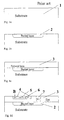
- FIGs. 1a-d A prior art method in the fabrication of a vertical bipolar NPN transistor is illustrated in Figs. 1a-d.
- a P-type doped bulk substrate 1 is provided, a buried collector layer region 2 is formed by ion implantation, a doped epitaxial semiconductor layer 3 is formed thereon, a base layer region including an extrinsic base layer region 4 and an intrinsic base layer region 6 is formed in the doped epitaxial semiconductor layer 3 above the buried collector layer region 2, an emitter layer region 5 is formed in the intrinsic base layer region 6, and a highly doped sinker or contact 7 is formed in the doped epitaxial semiconductor layer 3 to obtain an electric contact to the buried collector layer region 2.
- the lateral extensions and locations of the base 4, 6 and emitter 5 layer regions, and of the buried collector layer region 2 are selected, as seen in Fig. 1d, to create an overlap between the base 4, 6 and emitter 5 layer regions, and the buried collector layer region 3, as seen from above.
- the overlap extends essentially along the complete extension of the base 4, 6 and emitter 5 layer regions, i.e. the buried collector layer region 3 is basically present beneath the entire transistor.
- Such a bipolar transistor can be designed to have excellent high frequency performance and very low collector resistance. However, such a design does not provide for optimum breakdown voltage capabilities.
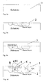
- the present invention remedies this problem, and a first embodiment thereof is described below with reference to Figs. 2a-d and Figs. 1a-d.
- At least two vertical bipolar transistors are fabricated simultaneously on a single die where the two vertical bipolar transistors have different voltage breakdown and high-frequency performance characteristics.
- a first one of the transistors is fabricated in accordance with Figs. 1a-d, whereas a second one is fabricated in accordance with Figs. 2a-d.
- the buried collector layer region 2 for the second transistor is formed by ion implantation in the substrate 1.
- a mask is applied having openings so that the buried collector layer region 2 comprises two laterally separated portions, which are connected at an end of the transistor located along the normal of the plane of the cross-section of Figs. 2a-d.
- the mask may have the general shape of a U (if the separated portions are connected to each other at one end only) or may be generally ring-shaped (if the separated portions are connected to each other at two opposite ends).
- the buried collector layer regions 2 of all the bipolar transistors of the same doping type on the die are of course formed simultaneously.
- the doped epitaxial semiconductor layer 3 is deposited as disclosed with reference to Figs 1a-d.
- a base layer region including an extrinsic base layer region 4 and an intrinsic base layer region 6 for the second transistor is formed in the doped epitaxial semiconductor layer 3 above the buried collector layer region 2 of the second transistor, an emitter layer region 5 is formed in the intrinsic base layer region 6 of the second transistor, and a highly doped sinker or contact 7 is formed in the doped epitaxial semiconductor layer 3 to obtain an electric contact to the buried collector layer region 2 of the second transistor.
- the emitter layer region 5 of the second transistor is advantageously symmetric with respective to a vertical plane schematically indicated by 11, wherein the two laterally separated portions of the buried collector layer region 2 are arranged on either side of the vertical plane 11-
- the buried collector layer region 2 of the second transistor is selected to be laterally essentially separated from the emitter layer region 5, and optionally from the intrinsic base layer region 6, of the second transistor.
- the second transistor which thus has no buried collector directly under the emitter layer region 5, has an increased breakdown voltage to the cost of deteriorated high frequency performance.
- each transistor may be tailored, by selecting the lateral extension and the location of its buried collector layer region, to obtain a transistor having a desired trade-off between voltage breakdown and high-frequency performance characteristics.
- Fabricated test structures have shown an increased breakdown voltage already for very short distances between the two separated buried collector layer region portions.
- a second embodiment of the present invention is described with reference to Figs. 3a-d.
- At least two vertical bipolar transistors are fabricated simultaneously on a single die where the two vertical bipolar transistors have different voltage breakdown and high-frequency performance characteristics.
- a first one of the transistors is fabricated in accordance with figs. 1a-d or according to Figs. 2a-d, whereas a second one is fabricated in accordance with Figs. 3a-d.
- the transistor of Figs. 3a-d is fabricated similar to the transistor of Fig. 2a-d. However, the buried collector layer region 2 is formed only at one side of the vertical symmetry plane 11. This layout is particularly an option for a transistor having a sinker or collector contact 7 only at one side of the transistor as being illustrated in Fig. 3d. By this embodiment, the breakdown voltage is increased even further.
- a third embodiment of the present invention comprises the simultaneous manufacturing of at least two vertical bipolar transistors on a single die, where the two vertical bipolar transistors have different voltage breakdown and high-frequency performance characteristics.
- a first one of the transistors is fabricated in accordance with Figs. 1a-d, in accordance with Figs. 2a-d, or in accordance with Figs. 3a-d, whereas a second one is fabricated in accordance with Figs. 4a-d.
- the transistor of Figs. 4a-d is fabricated similar to the transistor of Fig. 2a-d.
- the collector comprises a selectively implanted collector (SIC).
- the SIC implant is formed beneath the intrinsic base preferably in contact with the buried collector layer region 2.
- the buried collector layer region 2 will have a major impact on both the breakdown and the Early voltage also if the buried collector layer region 2 reaches the edge of the active emitter/base region, as seen from above. The closer the buried collector layer region 2 gets to the emitter/base region, the less impact it will have on the increase of the collector resistance.
- At least two vertical bipolar transistors are fabricated simultaneously on a single die where the two vertical bipolar transistors have different voltage breakdown and high-frequency performance characteristics.
- the transistors are fabricated on a silicon-on-insulator (SOI) substrate.
- a first one of the transistors is fabricated similar to Figs. 1a-a, whereas a second one is fabricated similar to Figs. 2a-d, but with the difference that the transistors are formed on the SOI substrate.
- a P-type substrate with buried oxide layer (SOI) 1 is provided and buried collector layer regions for the transistors are formed, the buried collector layer region for the second transistor being shown as detail 2 in Fig. 5b.
- a doped epitaxial semiconductor layer 3 is formed thereon, and base layer regions, emitter layer regions, and sinkers or collector contacts for the two transistors are formed in the doped epitaxial semiconductor layer 3.
- the lateral extensions and locations of the base and emitter layer regions and of the buried collector layer region of the first transistor are selected to create an overlap between the base and emitter layer regions, and the buried collector layer region similar to the overlap shown in Fig. 1d.
- the lateral extensions and locations of the base 4, 6 and emitter 5 layer regions, and of the buried collector layer region 2 of the second transistor are selected, as seen in Fig. 5d, to create an overlap between the base 4, 6 and emitter 5 layer regions, and the buried collector layer region 3 similar to the overlap shown in Fig. 2d.
- the SOI substrate base embodiment will have the same advantages as the previously described embodiments have. It shall be understood by a person skilled in the art that transistors similar to those of Figs. 3a-d and 4a-d may be formed together with other transistors on an SOI substrate.
- the collector resistance can be kept very low while the breakdown voltage is increased.
- isolation structures such as e.g. deep trenches, may be formed to surround each of the transistors in any of the above embodiments.
- the present invention increases the flexibility for trade-off between many parameters such as breakdown voltage, Early voltage, current gain, cut-off frequency and collector resistance.
Landscapes
- Bipolar Transistors (AREA)
- Bipolar Integrated Circuits (AREA)
Abstract
Description
- The present invention relates to a method for producing vertical bipolar transistors having different voltage breakdown and high-frequency performance characteristics on a single die. The invention also relates to an integrated circuit comprising transistors of the above kind.
- Advanced silicon bipolar or BiCMOS processes are used to manufacture high-performance high-frequency circuits, commonly used for radio and analogue functions in mobile wireless devices such as base stations for cellular networks, mobile and wireless phones, wireless networking for computers etc. The bipolar transistors have good high-frequency and analogue performance, high gain, and are excellent for driving large currents. The CMOS technology is preferably used for logic, and thus the combined BiCMOS technology is an excellent choice for mixed-signal systems.
- In high-frequency bipolar and BiCMOS processes, the bipolar transistor is implemented as a vertical device. The collector contact is placed at the side of the emitter/base structure. A buried collector, or subcollector, is used to achieve a low-ohmic path for the collector current from the active device via a highly doped vertical sinker to the collector contact. A common manner to form a buried collector is by doping the semiconductor substrate to high levels using preferably a patterned oxide mask, and then an epitaxial layer of silicon is grown on the substrate and the remaining parts of the transistor - base, emitter and collector contact - are formed on the top of the epitaxial layer.
- The collector-to-base and collector-to-emitter breakdown voltages (BVcbo, BVcoo , BVceo) are important device parameters. The breakdown voltages depend on the thickness and doping of the lowly doped collector epitaxial layer. For the breakdown voltage BVcoo, the current gain of the transistor is also involved, but the gain is set essentially by the emitter and base properties. As reach-through normally occurs prior to avalanche breakdown in the base-collector diode, the buried collector will affect the voltage breakdown. The distance between the buried collector and the base must be made short to insure good high-frequency performance and low collector resistance. However, the requested supply voltage will determine the minimum distance and thus affect the high-frequency performance. The trade-off between breakdown voltage and frequency performance in transistors is called the Johnson limit-
- In a typical mixed-signal circuit design, not all the bipolar devices need to be optimized for best frequency performance. Some devices may instead need higher breakdown voltages, such as transistors used for switching current or used in interfaces to other circuits. However, simultaneous manufacturing of devices with high breakdown voltage and devices with good hign-frequency performance on a single chip is not easily done without increased process complexity and increased costs associated therewith.
- U.S. Patent Application No. 2003/0094673 by Dunn et al., discloses a solution to this problem by using two different impurity types, arsenic and antimony, and different concentrations for the buried collector. This approach requires additional process steps as well as additional photo masks.
- U.S. Patent No. 6,770,952 by Babcock et al., discloses the manufacturing of devices with different collector design on a single wafer. However, the solution utilizes thin silicon-on-insulator (SOI) technology, and can not be used in conventional BiCMOS technology on bulk wafers.
- The present invention discloses a method to increase the breakdown voltage by using different collector layouts for different transistors on the very same die or chip. This makes it possible to optimise RF performance for a fixed breakdown voltage and offers, together with conventional design, the possibility of several levels of supply voltage on the same die. The inventive method will not cause any increase in the process complexity since only the mask layout of the devices are affected.
- The conventional method to form the buried collector is to let the collector region expand under the complete device or, in some cases, under the complete active area or emitter-base area.
- According to an aspect of the present invention there is provided a method comprising the steps of forming, for each of the vertical bipolar transistors fabricated on a single die, a buried collector region, and base and emitter regions above the buried collector region. For each of the vertical bipolar transistors, the lateral extensions and locations of the base and emitter regions and of the buried collector region are selected to create an overlap between the base and emitter regions, and the buried collector region, as seen from above, and at least some of the overlaps are selected to be different.
- It has been found that the location and lateral extension of the buried collector region with respect to the base and emitter regions strongly affect the voltage breakdown and high-frequency performance characteristics. Also the collector resistance is affected.
- Thus by selecting the lateral extension and the location of the buried collector region for a given transistor, a desired trade-off between voltage breakdown and high-frequency performance characteristics can be obtained.
- Preferably, some of the vertical bipolar transistors may each have a buried collector region comprising two laterally separated portions arranged on either side of a symmetry plane of the transistor. The portions are connected to one another at an end of the transistor lying outside of the base/emitter regions. Hereby an increased breakdown voltage is obtained to the cost of deteriorated high-frequency performance.
- Additionally or alternatively, some of the vertical bipolar transistors may each have a buried collector region arranged on one side only of a symmetry plane of the transistor, leaving a main portion of the transistor without the buried collector region. This will further increase the reach-through voltage and hence improve the voltage capability.
- The methods of the present invention are preferably implemented in BiCMOS processes or in bipolar only processes.
- Further characteristics of the invention and advantages thereof will be evident from the detailed description of preferred embodiments of the present invention given hereinafter and the accompanying Figs. 1-5, which are given by way of illustration only, and thus, are not limitative of the present invention.
-
- Figs. 1a-d are highly enlarged schematic cross-sectional views of a portion of a semiconductor structure during processing according to prior art.
- Figs. 2a-d, 3a-d, 4a-d, and 5a-d are highly enlarged schematic cross-sectional views of a portion of a semiconductor structure during processing according to different embodiments of the present invention.
- Identical reference numerals are used throughout the Figures to indicate similar components and parts.
- In order to understand the present invention various embodiments will be described. It will be apparent to one skilled in the art that the invention may be practiced in other embodiments that depart from those explicitly disclosed. In other instances, detailed descriptions of methods well-known to one skilled in the art are omitted.
- A prior art method in the fabrication of a vertical bipolar NPN transistor is illustrated in Figs. 1a-d. A P-type doped
bulk substrate 1 is provided, a buriedcollector layer region 2 is formed by ion implantation, a dopedepitaxial semiconductor layer 3 is formed thereon, a base layer region including an extrinsic base layer region 4 and an intrinsicbase layer region 6 is formed in the dopedepitaxial semiconductor layer 3 above the buriedcollector layer region 2, anemitter layer region 5 is formed in the intrinsicbase layer region 6, and a highly doped sinker orcontact 7 is formed in the dopedepitaxial semiconductor layer 3 to obtain an electric contact to the buriedcollector layer region 2. - The lateral extensions and locations of the
base 4, 6 andemitter 5 layer regions, and of the buriedcollector layer region 2 are selected, as seen in Fig. 1d, to create an overlap between thebase 4, 6 and emitter 5 layer regions, and the buriedcollector layer region 3, as seen from above. The overlap extends essentially along the complete extension of thebase 4, 6 andemitter 5 layer regions, i.e. the buriedcollector layer region 3 is basically present beneath the entire transistor. - Such a bipolar transistor can be designed to have excellent high frequency performance and very low collector resistance. However, such a design does not provide for optimum breakdown voltage capabilities.
- The present invention remedies this problem, and a first embodiment thereof is described below with reference to Figs. 2a-d and Figs. 1a-d.
- At least two vertical bipolar transistors are fabricated simultaneously on a single die where the two vertical bipolar transistors have different voltage breakdown and high-frequency performance characteristics. A first one of the transistors is fabricated in accordance with Figs. 1a-d, whereas a second one is fabricated in accordance with Figs. 2a-d.
- The buried
collector layer region 2 for the second transistor is formed by ion implantation in thesubstrate 1. - A mask is applied having openings so that the buried
collector layer region 2 comprises two laterally separated portions, which are connected at an end of the transistor located along the normal of the plane of the cross-section of Figs. 2a-d. Thus, given a linear transistor layout, the mask may have the general shape of a U (if the separated portions are connected to each other at one end only) or may be generally ring-shaped (if the separated portions are connected to each other at two opposite ends). The buriedcollector layer regions 2 of all the bipolar transistors of the same doping type on the die are of course formed simultaneously. - Then, the doped
epitaxial semiconductor layer 3 is deposited as disclosed with reference to Figs 1a-d. A base layer region including an extrinsic base layer region 4 and an intrinsicbase layer region 6 for the second transistor is formed in the dopedepitaxial semiconductor layer 3 above the buriedcollector layer region 2 of the second transistor, anemitter layer region 5 is formed in the intrinsicbase layer region 6 of the second transistor, and a highly doped sinker orcontact 7 is formed in the dopedepitaxial semiconductor layer 3 to obtain an electric contact to the buriedcollector layer region 2 of the second transistor. - The
emitter layer region 5 of the second transistor is advantageously symmetric with respective to a vertical plane schematically indicated by 11, wherein the two laterally separated portions of the buriedcollector layer region 2 are arranged on either side of the vertical plane 11- - The buried
collector layer region 2 of the second transistor is selected to be laterally essentially separated from theemitter layer region 5, and optionally from the intrinsicbase layer region 6, of the second transistor. - The second transistor, which thus has no buried collector directly under the
emitter layer region 5, has an increased breakdown voltage to the cost of deteriorated high frequency performance. - Generally, different vertical bipolar transistors may be manufactured on the same die, which have different layouts of their buried collector layer regions. Each transistor can generally be tailored, by selecting the lateral extension and the location of its buried collector layer region, to obtain a transistor having a desired trade-off between voltage breakdown and high-frequency performance characteristics.
- Fabricated test structures have shown an increased breakdown voltage already for very short distances between the two separated buried collector layer region portions.
- A second embodiment of the present invention is described with reference to Figs. 3a-d. At least two vertical bipolar transistors are fabricated simultaneously on a single die where the two vertical bipolar transistors have different voltage breakdown and high-frequency performance characteristics. A first one of the transistors is fabricated in accordance with figs. 1a-d or according to Figs. 2a-d, whereas a second one is fabricated in accordance with Figs. 3a-d.
- The transistor of Figs. 3a-d is fabricated similar to the transistor of Fig. 2a-d. However, the buried
collector layer region 2 is formed only at one side of the vertical symmetry plane 11. This layout is particularly an option for a transistor having a sinker orcollector contact 7 only at one side of the transistor as being illustrated in Fig. 3d. By this embodiment, the breakdown voltage is increased even further. - A third embodiment of the present invention comprises the simultaneous manufacturing of at least two vertical bipolar transistors on a single die, where the two vertical bipolar transistors have different voltage breakdown and high-frequency performance characteristics. A first one of the transistors is fabricated in accordance with Figs. 1a-d, in accordance with Figs. 2a-d, or in accordance with Figs. 3a-d, whereas a second one is fabricated in accordance with Figs. 4a-d.
- The transistor of Figs. 4a-d is fabricated similar to the transistor of Fig. 2a-d. However, the collector comprises a selectively implanted collector (SIC). The SIC implant is formed beneath the intrinsic base preferably in contact with the buried
collector layer region 2. - In this case the buried
collector layer region 2 will have a major impact on both the breakdown and the Early voltage also if the buriedcollector layer region 2 reaches the edge of the active emitter/base region, as seen from above. The closer the buriedcollector layer region 2 gets to the emitter/base region, the less impact it will have on the increase of the collector resistance. - Finally, with reference to Figs. 5a-d a fourth embodiment of the invention will be described.
- At least two vertical bipolar transistors are fabricated simultaneously on a single die where the two vertical bipolar transistors have different voltage breakdown and high-frequency performance characteristics. The transistors are fabricated on a silicon-on-insulator (SOI) substrate.
- A first one of the transistors is fabricated similar to Figs. 1a-a, whereas a second one is fabricated similar to Figs. 2a-d, but with the difference that the transistors are formed on the SOI substrate.
- A P-type substrate with buried oxide layer (SOI) 1 is provided and buried collector layer regions for the transistors are formed, the buried collector layer region for the second transistor being shown as
detail 2 in Fig. 5b. A dopedepitaxial semiconductor layer 3 is formed thereon, and base layer regions, emitter layer regions, and sinkers or collector contacts for the two transistors are formed in the dopedepitaxial semiconductor layer 3. - The lateral extensions and locations of the base and emitter layer regions and of the buried collector layer region of the first transistor are selected to create an overlap between the base and emitter layer regions, and the buried collector layer region similar to the overlap shown in Fig. 1d. The lateral extensions and locations of the
base 4, 6 andemitter 5 layer regions, and of the buriedcollector layer region 2 of the second transistor are selected, as seen in Fig. 5d, to create an overlap between thebase 4, 6 andemitter 5 layer regions, and the buriedcollector layer region 3 similar to the overlap shown in Fig. 2d. - In general the SOI substrate base embodiment will have the same advantages as the previously described embodiments have. It shall be understood by a person skilled in the art that transistors similar to those of Figs. 3a-d and 4a-d may be formed together with other transistors on an SOI substrate.
- By using the SOI substrate-based embodiment, the collector resistance can be kept very low while the breakdown voltage is increased.
- It shall be appreciated that isolation structures such as e.g. deep trenches, may be formed to surround each of the transistors in any of the above embodiments.
- While the embodiments above can be implemented in an existing BiCMOS or bipolar only process without other changes than that of the collector design, the increased breakdown and/or Early voltage can be used to increase the margin for other parameters by changing other process steps.
- Generally, the present invention increases the flexibility for trade-off between many parameters such as breakdown voltage, Early voltage, current gain, cut-off frequency and collector resistance.
Claims (17)
- A method for producing vertical bipolar transistors having different voltage breakdown and high-frequency performance characteristics on a single die, characterized by the steps of:- forming, for each of the vertical bipolar transistors, a buried collector region, and base (4, 6) and emitter (5) regions above the buried collector region (2), wherein- for each of the vertical bipolar transistors, the lateral extensions and locations of the base and emitter regions, and of the buried collector region are selected to create an overlap between the base and emitter regions, and the buried collector region, as seen from above, and- at least some of the overlaps are selected to be different.
- The method of claim 1, wherein, in at least one of the vertical bipolar transistors, the overlap extends along the complete extension of the base and emitter regions.
- The method of claim 1 or 2, wherein, in at least one of the vertical bipolar transistors, the overlap extends along a portion only of the extension of the base and emitter regions.
- The method of any of claims 1-3, wherein, in at least one of the vertical bipolar transistors, the buried collector region (2) is laterally separated from the emitter region (5).
- The method of any of claims 1-4, wherein, in at least one of the vertical bipolar transistors, the base region (4, 6) comprises an intrinsic base region (6) and an extrinsic base region (6), and the buried collector region (2) is laterally separated from the intrinsic base region (6).
- The method of any of claims 1-5, wherein, in at least one of the vertical bipolar transistors, the emitter region (5) is symmetric with respective to a vertical plane, and the buried collector region (2) extends only at one side of said vertical plane.
- The method of any of claims 1-6, wherein, in at least one of the vertical bipolar transistors, the emitter region (5) is symmetric with respective to a vertical plane, and the buried collector region (2) comprises two laterally separated portions arranged on either side of the vertical plane.
- The method of any of claims 1-6, wherein, in at least one of the vertical bipolar transistors, the lateral extension and the location of the buried collector region (2) is selected to obtain a transistor having a selected trade-off between voltage breakdown and high-frequency performance characteristics.
- The method of any of claims 1-8, wherein the vertical bipolar transistors are produced on a bulk substrate (1).
- The method of any of claims 1-8, wherein the vertical bipolar transistors are produced on an SOI substrate (1).
- The method of any of claims 1-10, wherein said method includes the step of forming a selective implanted collector (SIC) for at least some of the vertical bipolar transistors.
- The method of any of claims 1-11, wherein said method is implemented in a BiCMOS process or in a bipolar only process.
- The method of any of claims 1-12, wherein isolation structures, particularly deep trenches, are formed to surround each of the vertical bipolar transistors.
- An integrated circuit comprising vertical bipolar transistors having different voltage breakdown and high-frequency performance characteristics, characterized in that:- the vertical bipolar transistors comprise each base (4, 6) and emitter (5) regions above a buried collector region (2), wherein- the base and emitter regions, and the buried collector region of each of the vertical bipolar transistors have lateral extensions and are located so that an overlap between the base and emitter regions, and the buried collector region, as seen from above, is present, and- at least some of the overlaps are different.
- The integrated circuit of claim 14, wherein, in at least one of the vertical bipolar transistors, the buried collector region (3) is laterally separated from the emitter region (5).
- The integrated circuit of claim 14 or 15, wherein, in at least one of the vertical bipolar transistors, the emitter region (5) is symmetric with respective to a vertical plan (11), and the buried collector region (2) extends only at one side of said vertical plane.
- The integrated circuit of any of claims 14-16, wherein, in at least one of the vertical bipolar transistors, the emitter region (5) is symmetric with respective to a vertical plan (11), and the buried collector region (2) comprises two laterally separated portions arranged on either side of the vertical plane.
Priority Applications (3)
| Application Number | Priority Date | Filing Date | Title |
|---|---|---|---|
| EP04023345.4A EP1643549B8 (en) | 2004-09-30 | 2004-09-30 | Method for producing vertical bipolar transistors and integrated circuit with vertical bipolar transistors |
| CNB2005101199460A CN100543948C (en) | 2004-09-30 | 2005-09-30 | Vertical bipolar transistor manufacturing method and integrated circuit |
| US11/241,807 US7495312B2 (en) | 2004-09-30 | 2005-09-30 | Method for producing vertical bipolar transistors and integrated circuit |
Applications Claiming Priority (1)
| Application Number | Priority Date | Filing Date | Title |
|---|---|---|---|
| EP04023345.4A EP1643549B8 (en) | 2004-09-30 | 2004-09-30 | Method for producing vertical bipolar transistors and integrated circuit with vertical bipolar transistors |
Publications (3)
| Publication Number | Publication Date |
|---|---|
| EP1643549A1 true EP1643549A1 (en) | 2006-04-05 |
| EP1643549B1 EP1643549B1 (en) | 2018-09-05 |
| EP1643549B8 EP1643549B8 (en) | 2019-03-06 |
Family
ID=34926800
Family Applications (1)
| Application Number | Title | Priority Date | Filing Date |
|---|---|---|---|
| EP04023345.4A Expired - Lifetime EP1643549B8 (en) | 2004-09-30 | 2004-09-30 | Method for producing vertical bipolar transistors and integrated circuit with vertical bipolar transistors |
Country Status (3)
| Country | Link |
|---|---|
| US (1) | US7495312B2 (en) |
| EP (1) | EP1643549B8 (en) |
| CN (1) | CN100543948C (en) |
Cited By (2)
| Publication number | Priority date | Publication date | Assignee | Title |
|---|---|---|---|---|
| WO2011053926A3 (en) * | 2009-11-02 | 2011-06-30 | Analog Devices, Inc. | Bipolar transistor |
| US10199482B2 (en) | 2010-11-29 | 2019-02-05 | Analog Devices, Inc. | Apparatus for electrostatic discharge protection |
Families Citing this family (8)
| Publication number | Priority date | Publication date | Assignee | Title |
|---|---|---|---|---|
| US8134212B2 (en) * | 2008-08-08 | 2012-03-13 | Texas Instruments Incorporated | Implanted well breakdown in high voltage devices |
| CN102347354B (en) * | 2010-08-05 | 2013-04-24 | 上海华虹Nec电子有限公司 | Germanium-silicon heterojunction bipolar transistor and manufacturing method thereof |
| US8791546B2 (en) | 2010-10-21 | 2014-07-29 | Freescale Semiconductor, Inc. | Bipolar transistors having emitter-base junctions of varying depths and/or doping concentrations |
| CN102544119B (en) * | 2010-12-13 | 2014-07-09 | 上海华虹宏力半导体制造有限公司 | PN(positive negative) junction varactor in Bi CMOS (complementary metal oxide semiconductor) process and manufacturing method thereof |
| CN103066101B (en) * | 2011-10-24 | 2016-08-17 | 上海华虹宏力半导体制造有限公司 | Germanium silicium HBT device and manufacture method |
| CN103066119B (en) * | 2011-10-24 | 2015-04-08 | 上海华虹宏力半导体制造有限公司 | Germanium silicon heterojunction bipolar transistor and manufacturing method thereof |
| US9099489B2 (en) | 2012-07-10 | 2015-08-04 | Freescale Semiconductor Inc. | Bipolar transistor with high breakdown voltage |
| US8847358B2 (en) | 2012-08-21 | 2014-09-30 | Freescale Semiconductor, Inc. | Bipolar transistor |
Citations (4)
| Publication number | Priority date | Publication date | Assignee | Title |
|---|---|---|---|---|
| US5698459A (en) * | 1994-10-07 | 1997-12-16 | National Semiconductor Corporation | Fabrication of bipolar transistors using selective doping to improve performance characteristics |
| US6004855A (en) * | 1988-04-11 | 1999-12-21 | Synergy Semiconductor Corporation | Process for producing a high performance bipolar structure |
| US20020158309A1 (en) * | 2001-04-30 | 2002-10-31 | Leland Swanson | High breakdown voltage transistor and method |
| US20040048428A1 (en) * | 2002-08-15 | 2004-03-11 | Nec Electronics Corporation | Semiconductor device and method of manufacturing the same |
Family Cites Families (4)
| Publication number | Priority date | Publication date | Assignee | Title |
|---|---|---|---|---|
| US6521974B1 (en) * | 1999-10-14 | 2003-02-18 | Hitachi, Ltd. | Bipolar transistor and manufacturing method thereof |
| US6770952B2 (en) * | 2001-04-30 | 2004-08-03 | Texas Instruments Incorporated | Integrated process for high voltage and high performance silicon-on-insulator bipolar devices |
| US7064416B2 (en) | 2001-11-16 | 2006-06-20 | International Business Machines Corporation | Semiconductor device and method having multiple subcollectors formed on a common wafer |
| DE10306597B4 (en) * | 2003-02-17 | 2005-11-17 | Infineon Technologies Ag | A method of fabricating a semiconductor structure with increased breakdown voltage by underlying subcollector section |
-
2004
- 2004-09-30 EP EP04023345.4A patent/EP1643549B8/en not_active Expired - Lifetime
-
2005
- 2005-09-30 CN CNB2005101199460A patent/CN100543948C/en not_active Expired - Fee Related
- 2005-09-30 US US11/241,807 patent/US7495312B2/en active Active
Patent Citations (4)
| Publication number | Priority date | Publication date | Assignee | Title |
|---|---|---|---|---|
| US6004855A (en) * | 1988-04-11 | 1999-12-21 | Synergy Semiconductor Corporation | Process for producing a high performance bipolar structure |
| US5698459A (en) * | 1994-10-07 | 1997-12-16 | National Semiconductor Corporation | Fabrication of bipolar transistors using selective doping to improve performance characteristics |
| US20020158309A1 (en) * | 2001-04-30 | 2002-10-31 | Leland Swanson | High breakdown voltage transistor and method |
| US20040048428A1 (en) * | 2002-08-15 | 2004-03-11 | Nec Electronics Corporation | Semiconductor device and method of manufacturing the same |
Non-Patent Citations (2)
| Title |
|---|
| GILBERT P V ET AL: "QUASI-DIELECTRICALLY ISOLATED BIPOLAR JUNCTION TRANSISTOR WITH SUBCOLLECTOR FABRICATED USING SILICON SELECTIVE EPITAXY", IEEE TRANSACTIONS ON ELECTRON DEVICES, IEEE INC. NEW YORK, US, vol. 38, no. 7, 1 July 1991 (1991-07-01), pages 1660 - 1665, XP000206665, ISSN: 0018-9383 * |
| HEINEMANN B ET AL: "Novel collector design for high-speed SiGe:C HBTs", INTERNATIONAL ELECTRON DEVICES MEETING 2002. IEDM. TECHNICAL DIGEST. SAN FRANCISCO, CA, DEC. 8 - 11, 2002, NEW YORK, NY : IEEE, US, 8 December 2002 (2002-12-08), pages 775 - 778, XP010626155, ISBN: 0-7803-7462-2 * |
Cited By (4)
| Publication number | Priority date | Publication date | Assignee | Title |
|---|---|---|---|---|
| WO2011053926A3 (en) * | 2009-11-02 | 2011-06-30 | Analog Devices, Inc. | Bipolar transistor |
| US8058704B2 (en) | 2009-11-02 | 2011-11-15 | Analog Devices, Inc. | Bipolar transistor |
| US8263469B2 (en) | 2009-11-02 | 2012-09-11 | Analog Devices, Inc. | Methods of forming a bipolar transistor |
| US10199482B2 (en) | 2010-11-29 | 2019-02-05 | Analog Devices, Inc. | Apparatus for electrostatic discharge protection |
Also Published As
| Publication number | Publication date |
|---|---|
| EP1643549B8 (en) | 2019-03-06 |
| CN100543948C (en) | 2009-09-23 |
| EP1643549B1 (en) | 2018-09-05 |
| CN1773683A (en) | 2006-05-17 |
| US20060076645A1 (en) | 2006-04-13 |
| US7495312B2 (en) | 2009-02-24 |
Similar Documents
| Publication | Publication Date | Title |
|---|---|---|
| US6838348B2 (en) | Integrated process for high voltage and high performance silicon-on-insulator bipolar devices | |
| US8115280B2 (en) | Four-terminal gate-controlled LVBJTs | |
| US10319716B2 (en) | Substrate isolation for low-loss radio frequency (RF) circuits | |
| US9570546B2 (en) | Bipolar transistor | |
| US6724066B2 (en) | High breakdown voltage transistor and method | |
| US20040048428A1 (en) | Semiconductor device and method of manufacturing the same | |
| US7732835B2 (en) | Vertical P-N junction device and method of forming same | |
| US11276770B2 (en) | Gate controlled lateral bipolar junction/heterojunction transistors | |
| EP1643549B1 (en) | Method for producing vertical bipolar transistors and integrated circuit with vertical bipolar transistors | |
| US20100032766A1 (en) | Bipolar Junction Transistor with a Reduced Collector-Substrate Capacitance | |
| JPH07326773A (en) | Diode and its preparation | |
| CN100435319C (en) | Fabrication method for integrated injection logic circuit | |
| KR20040000442A (en) | Process for making a high voltage npn bipolar device with improved ac performance | |
| US8421124B2 (en) | High-beta bipolar junction transistor and method of manufacture | |
| US8901669B2 (en) | Method of manufacturing an IC comprising a plurality of bipolar transistors and IC comprising a plurality of bipolar transistors | |
| US8563387B2 (en) | Transistor and method of manufacturing a transistor | |
| CN100550384C (en) | Integrated circuit arrangement with npn and pnp bipolar transistors and corresponding manufacturing method | |
| JP3953344B2 (en) | Stepped collector implant and method for forming the same | |
| CN116779542A (en) | Method and semiconductor device for integrating germanium-silicon heterojunction transistor in silicon-based self-aligned bipolar process | |
| US12557327B2 (en) | Semiconductor device and method for fabricating the same | |
| US10797132B2 (en) | Heterojunction bipolar transistor fabrication using resist mask edge effects | |
| JPH10335346A (en) | Lateral PNP bipolar electronic device and method of manufacturing the same | |
| KR20090031354A (en) | Bipolar Junction Transistors with Reduced Collector-Board Capacitance | |
| JP2023095570A (en) | semiconductor equipment | |
| JPH03259533A (en) | Semiconductor integrated circuit device |
Legal Events
| Date | Code | Title | Description |
|---|---|---|---|
| PUAI | Public reference made under article 153(3) epc to a published international application that has entered the european phase |
Free format text: ORIGINAL CODE: 0009012 |
|
| AK | Designated contracting states |
Kind code of ref document: A1 Designated state(s): AT BE BG CH CY CZ DE DK EE ES FI FR GB GR HU IE IT LI LU MC NL PL PT RO SE SI SK TR |
|
| AX | Request for extension of the european patent |
Extension state: AL HR LT LV MK |
|
| 17P | Request for examination filed |
Effective date: 20060508 |
|
| AKX | Designation fees paid |
Designated state(s): DE FR GB |
|
| RAP1 | Party data changed (applicant data changed or rights of an application transferred) |
Owner name: INFINEON TECHNOLOGIES AG |
|
| 17Q | First examination report despatched |
Effective date: 20130923 |
|
| GRAP | Despatch of communication of intention to grant a patent |
Free format text: ORIGINAL CODE: EPIDOSNIGR1 |
|
| INTG | Intention to grant announced |
Effective date: 20180321 |
|
| GRAS | Grant fee paid |
Free format text: ORIGINAL CODE: EPIDOSNIGR3 |
|
| GRAA | (expected) grant |
Free format text: ORIGINAL CODE: 0009210 |
|
| AK | Designated contracting states |
Kind code of ref document: B1 Designated state(s): DE FR GB |
|
| REG | Reference to a national code |
Ref country code: GB Ref legal event code: FG4D |
|
| REG | Reference to a national code |
Ref country code: FR Ref legal event code: PLFP Year of fee payment: 15 |
|
| REG | Reference to a national code |
Ref country code: DE Ref legal event code: R096 Ref document number: 602004053135 Country of ref document: DE |
|
| RIN2 | Information on inventor provided after grant (corrected) |
Inventor name: ANDERSSON, KARIN Inventor name: ALGOTSSON, PATRIK Inventor name: NORSTROEM, HANS |
|
| REG | Reference to a national code |
Ref country code: DE Ref legal event code: R097 Ref document number: 602004053135 Country of ref document: DE |
|
| PLBE | No opposition filed within time limit |
Free format text: ORIGINAL CODE: 0009261 |
|
| STAA | Information on the status of an ep patent application or granted ep patent |
Free format text: STATUS: NO OPPOSITION FILED WITHIN TIME LIMIT |
|
| 26N | No opposition filed |
Effective date: 20190606 |
|
| PGFP | Annual fee paid to national office [announced via postgrant information from national office to epo] |
Ref country code: GB Payment date: 20220920 Year of fee payment: 19 |
|
| PGFP | Annual fee paid to national office [announced via postgrant information from national office to epo] |
Ref country code: FR Payment date: 20220922 Year of fee payment: 19 |
|
| PGFP | Annual fee paid to national office [announced via postgrant information from national office to epo] |
Ref country code: DE Payment date: 20221116 Year of fee payment: 19 |
|
| REG | Reference to a national code |
Ref country code: DE Ref legal event code: R119 Ref document number: 602004053135 Country of ref document: DE |
|
| GBPC | Gb: european patent ceased through non-payment of renewal fee |
Effective date: 20230930 |
|
| PG25 | Lapsed in a contracting state [announced via postgrant information from national office to epo] |
Ref country code: GB Free format text: LAPSE BECAUSE OF NON-PAYMENT OF DUE FEES Effective date: 20230930 |
|
| PG25 | Lapsed in a contracting state [announced via postgrant information from national office to epo] |
Ref country code: GB Free format text: LAPSE BECAUSE OF NON-PAYMENT OF DUE FEES Effective date: 20230930 Ref country code: FR Free format text: LAPSE BECAUSE OF NON-PAYMENT OF DUE FEES Effective date: 20230930 Ref country code: DE Free format text: LAPSE BECAUSE OF NON-PAYMENT OF DUE FEES Effective date: 20240403 |