EP1643408B1 - Isolating software deployment over a network from external malicious intrusion - Google Patents
Isolating software deployment over a network from external malicious intrusion Download PDFInfo
- Publication number
- EP1643408B1 EP1643408B1 EP05108251A EP05108251A EP1643408B1 EP 1643408 B1 EP1643408 B1 EP 1643408B1 EP 05108251 A EP05108251 A EP 05108251A EP 05108251 A EP05108251 A EP 05108251A EP 1643408 B1 EP1643408 B1 EP 1643408B1
- Authority
- EP
- European Patent Office
- Prior art keywords
- network
- bare computer
- bare
- recited
- server
- Prior art date
- Legal status (The legal status is an assumption and is not a legal conclusion. Google has not performed a legal analysis and makes no representation as to the accuracy of the status listed.)
- Not-in-force
Links
- 238000004891 communication Methods 0.000 claims description 21
- 238000000034 method Methods 0.000 claims description 19
- 238000002955 isolation Methods 0.000 claims description 13
- 230000003993 interaction Effects 0.000 claims description 4
- 230000004044 response Effects 0.000 claims description 4
- 230000015654 memory Effects 0.000 description 15
- 230000003287 optical effect Effects 0.000 description 9
- 238000009434 installation Methods 0.000 description 4
- 230000006855 networking Effects 0.000 description 4
- 238000012545 processing Methods 0.000 description 4
- 241000700605 Viruses Species 0.000 description 3
- 238000005516 engineering process Methods 0.000 description 3
- 230000002093 peripheral effect Effects 0.000 description 3
- 230000009471 action Effects 0.000 description 2
- 238000013459 approach Methods 0.000 description 2
- 230000008901 benefit Effects 0.000 description 2
- 230000001419 dependent effect Effects 0.000 description 2
- 238000010586 diagram Methods 0.000 description 2
- ZXQYGBMAQZUVMI-GCMPRSNUSA-N gamma-cyhalothrin Chemical compound CC1(C)[C@@H](\C=C(/Cl)C(F)(F)F)[C@H]1C(=O)O[C@H](C#N)C1=CC=CC(OC=2C=CC=CC=2)=C1 ZXQYGBMAQZUVMI-GCMPRSNUSA-N 0.000 description 2
- 238000004519 manufacturing process Methods 0.000 description 2
- 230000005055 memory storage Effects 0.000 description 2
- 230000008569 process Effects 0.000 description 2
- 238000011900 installation process Methods 0.000 description 1
- 238000007726 management method Methods 0.000 description 1
- 230000007246 mechanism Effects 0.000 description 1
- 238000012544 monitoring process Methods 0.000 description 1
- 230000008520 organization Effects 0.000 description 1
- 230000001172 regenerating effect Effects 0.000 description 1
- 238000012546 transfer Methods 0.000 description 1
- 230000007723 transport mechanism Effects 0.000 description 1
Images

Classifications
-
- G—PHYSICS
- G06—COMPUTING; CALCULATING OR COUNTING
- G06F—ELECTRIC DIGITAL DATA PROCESSING
- G06F15/00—Digital computers in general; Data processing equipment in general
-
- H—ELECTRICITY
- H04—ELECTRIC COMMUNICATION TECHNIQUE
- H04L—TRANSMISSION OF DIGITAL INFORMATION, e.g. TELEGRAPHIC COMMUNICATION
- H04L63/00—Network architectures or network communication protocols for network security
- H04L63/14—Network architectures or network communication protocols for network security for detecting or protecting against malicious traffic
- H04L63/1441—Countermeasures against malicious traffic
-
- G—PHYSICS
- G06—COMPUTING; CALCULATING OR COUNTING
- G06F—ELECTRIC DIGITAL DATA PROCESSING
- G06F21/00—Security arrangements for protecting computers, components thereof, programs or data against unauthorised activity
- G06F21/50—Monitoring users, programs or devices to maintain the integrity of platforms, e.g. of processors, firmware or operating systems
- G06F21/57—Certifying or maintaining trusted computer platforms, e.g. secure boots or power-downs, version controls, system software checks, secure updates or assessing vulnerabilities
-
- H—ELECTRICITY
- H04—ELECTRIC COMMUNICATION TECHNIQUE
- H04L—TRANSMISSION OF DIGITAL INFORMATION, e.g. TELEGRAPHIC COMMUNICATION
- H04L67/00—Network arrangements or protocols for supporting network services or applications
- H04L67/34—Network arrangements or protocols for supporting network services or applications involving the movement of software or configuration parameters
-
- G—PHYSICS
- G06—COMPUTING; CALCULATING OR COUNTING
- G06F—ELECTRIC DIGITAL DATA PROCESSING
- G06F8/00—Arrangements for software engineering
- G06F8/60—Software deployment
-
- G—PHYSICS
- G06—COMPUTING; CALCULATING OR COUNTING
- G06F—ELECTRIC DIGITAL DATA PROCESSING
- G06F9/00—Arrangements for program control, e.g. control units
- G06F9/06—Arrangements for program control, e.g. control units using stored programs, i.e. using an internal store of processing equipment to receive or retain programs
- G06F9/44—Arrangements for executing specific programs
- G06F9/4401—Bootstrapping
- G06F9/4416—Network booting; Remote initial program loading [RIPL]
Abstract
Description
- This invention generally relates to operating systems and other software of computers on a network.
- One of the quickest and easiest ways to add a new "bare server"― which is a server not having an operating system―to a network is to plug it into the network and use a deployment server to deploy a disk "image" or setup files of an operating system to the bare server. The bare server saves this image to its hard disk drive or equivalent storage and then reboots. Once it reboots, it will be running with the newly deployed operating system.
- Patches to operating systems are deployed frequently and therefore the operating system image goes out-of-date, or stale, very quickly. Regenerating new images or setup files to deploy to bare servers so that they contain the latest patches when they are first booted is time consuming.
- Therefore, it is desirable for the newly deployed servers with an otherwise "stale" operating system to be updated immediately upon first post-deployment reboot. After the first post-deployment reboot, it typically acquires the necessary updates via the network, usually from a public network (such as the Internet) or from an intranet server.
- However, the network (especially an untrustworthy network such as the Internet) may be susceptible to malicious intrusion, such as a virus, Trojan horse, or other network-based attack. It is not uncommon for a newly deployed "stale" server to be "attacked" by malicious code (like a virus or Trojan horse) via the network before it is able to acquire the necessary updates that would protect it from such attacks.
- This is a real possibility, as many malicious programs take less than a second to corrupt a server running an out-of-date operating system. The MS Blaster virus, for instance, can corrupt a stale and unprotected server within tenths of a second.
- To partially combat this problem, a bare server can be connected to a deployment server, such as by manually plugging a cable into both servers or by way of using a dedicated network switch, without being connected to a production or "live" network. Through this cable or dedicated switch, the deployment server can deploy an operating system image to the bare server. The server can then be rebooted with the operating system. Once this is done, updates can be installed, usually by hand with compact disks, to make the operating system, applications and system services optimally secure. Once updated, the server can then be plugged into the network.
- While this partial solution may reduce the server's vulnerability to attack, it is time consuming and error prone. An information technology specialist can spend many hours connecting bare servers directly to a deployment server, deploying images, installing updates, disconnecting the servers from the deployment server, and then connecting them to the production or live network. In some ways, this defeats the purpose of automatic software deployment.
- Also, to partially combat this problem, the operating system and updates can be manually installed on a bare server, usually with many compact disks, prior to connecting the server to the network. Manually installing an operating system and updates, however, is also time consuming and tedious; it can take hours for each server. This, too, defeats the purpose of automatic software deployment.
- There is, therefore, a need for a secure way to deploy, over a network, an operating system and updates to a bare server, so that it is not susceptible to malicious network-based intrusion.
- Microsoft Corporation: "Using Windows XP Professional with Service Pack 2 in a Managed Environment: Controlling Communication with the Internet" Microsoft Publication, July 2004, relates to Windows XP Professional with Service Pack 2 in a managed environment. The benefits of Windows Update and Automatic Updates is described and it is shown how Windows Update and Automatic Updates communicate with sites on the internet and how to control Windows Update and Automatic Updates to limit the flow of information to and from the internet. Moreover, the concept of automated installation and deployment is introduced. By using an automated installation method, it can be insured that certain components and applications are not available on an organization's computer or that certain components and applications are preconfigured in such a way that helps prevent unwanted communication over the internet, If the remote installation services (RIS), the operating system by itself or a complete computer configuration, including desktop settings and applications, can be installed. RIS installations can be either CD based or image based.
- Ian Brown, Kevin Dooley: "Cisco Cookbook, Field-tested solutions to Cisco Router Problems", April 5, 2004, Oreilly, Internet, describes field tested solutions to Cisco router problems. Chapter 17 describes the simple network management protocol (SNMP). SNMP defines two main types of entities, managers and agents. A manager is a server that runs network management software that is responsible for a particular network. An agent is an embedded piece of software that resides on a remote device that is wished to be managed. Read only SNMP services and read-write SNMP services can be enabled on the Cisco router. In addition, the SNMP can be used to modify the router's running configuration.
- It is the object of the present invention to increase the security of a prior art installation process.
- This object is solved by the subject matter of the independent claims. Preferred embodiments are defined by the dependent claims.
- Described herein is an implementation for secure deployment, over a network, of software product (e.g., an operating system, an application program, and a software service) and updates to a bare computer (e.g., a server), so that it is not susceptible to malicious network-based intrusion.
- The same numbers are used throughout the drawings to reference like elements and features.
-
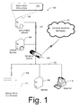
Fig. 1 is an exemplary operating environment for an implementation described herein. The exemplary operating environment is shown having exemplary servers, a network susceptible to malicious intrusion, and bare computers. -
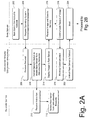
Figs. 2A and2B show a flow diagram showing a methodological implementation described herein. -
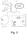
Fig. 3 is a block diagram of an alternative exemplary operating environment for an implementation described herein. -
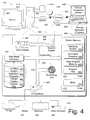
Fig. 4 is an example of a computing operating environment capable of (wholly or partially) implementing at least one embodiment described herein. - The following description sets forth techniques for secure deployment, over a network, of an operating system and updates to a bare server so that it is not susceptible to malicious network-based intrusion. The techniques may be implemented in many ways, including (but not limited to) program modules, general- and special-purpose computing systems, network servers and equipment, dedicated electronics and hardware, and as part of one or more computer networks.
- An exemplary implementation of these techniques may be referred to as an exemplary isolator of vulnerable and newly deployed software or simply as an "exemplary isolator."
- Via an automated software deployment service, datacenters have the ability to rapidly deploy software (e.g., operating systems) based on transferring reference "images" across a network. Rapid system deployments are a huge benefit to datacenter operators; however, rapidly deploying a new server only to have it immediately attacked is a serious short-coming.
-
Fig. 1 discloses an operational environment 100 (or "architecture") in which software is automatically deployed. This is also an exemplary operational environment in which the exemplary isolator may operate. - This exemplary
operational environment 100 is shown having several components coupled across a central andsecure network 120. Those network-coupled components include adeployment server 102, anupdate server 104, and anetwork switch 130. Thisoperational environment 100 is also shown having several components coupled across a switchable and possiblysecure network 122, and those components are a rack-mounted bare server 114 (one or several servers mounted in a rack 108), abare server 116, and abare desktop computer 118. Furthermore, the environment is also shown with an untrustworthy network 140 (e.g., the Internet) being switchably coupled to the two other networks (120 and 122) via thenetwork switch 130. - The
deployment server 102 performs the act of software deployment. Thedeployment server 102 comprises computer-readable media capable of performing one or more of the processes described below. These media can comprise adeployment application 110, for instance. - As illustrated in
Fig. 1 , the exemplary isolator is implemented by thedeployment application 110 of thedeployment server 102. It is also implemented, at least in part, by thenetwork switch 130. - The
update server 104 also comprises computer-readable media, here capable of deploying software patches, fixes, and the like, such as to update an out-of date operating system for improving its operation, e.g., its security capabilities. These updates can improve resistance to various malicious code later received by the bare server, described in greater detail below. - Three exemplary bare computers are also shown, the
bare server 114 inrack 108, the bare stand-alone server 116, and thebare desktop 118. Each of the bare computers has a software or hardware application sufficient to enable the bare computer to request, receive, and follow basic instructions, such as from thedeployment application 110. - The
operational environment 100 communicates across thenetwork - These
networks network switch 130. This switch is capable of receiving instructions from a server (such as the deployment server 102) to select which networks (and indeed which devices on those networks) may communicate with each other. - For example, the
network switch 130 may be directed to isolatenetwork 122 from theuntrustworthy network 140. In that way, the devices onnetwork 122 may communicate with devices onnetwork 120, but cannot communicate with devices on theuntrustworthy network 140 and vice versa. -
Figs. 2A and2B show a methodological implementation of the exemplary isolator of vulnerable and newly deployed software. This methodological implementation may be performed in software, hardware, or a combination thereof For ease of understanding, the method steps are delineated as separate steps; however, these separately delineated steps should not be construed as necessarily order dependent in their performance. - The method of
Figs. 2A and2B is illustrated as a series of blocks representing individual operations or acts performed by the deployment server 102 (such as with deploying application 110), thenetwork switch 130, and a bare server (e.g., server 116). - Those exemplary operations and acts performed by the
deployment server 102―to effectively isolate the newly deployed bare server while it is left unprotected before and during its update―are illustrated under the heading "Deployment Server/Deployment Application." - Those exemplary operations and acts performed by a bare server (e.g., server 116)―for securely receiving the deployed image and updating the operating system―are illustrated under the heading "Bare Server."
- Those exemplary operations and acts performed by the
network switch 130―to selectively isolate (in response to instructions to do so) the newly deployed bare server while it is left unprotected before and during its update―are illustrated under the heading "Network Switch." - At 202 of
Fig. 2A , a bare computer is connected to network 122. For example,bare server 114 is plugged into the network viarack 108, though other bare computers, such as stand-alone server 116 ordesktop 118, can instead be connected to the network. - At 204, the bare server communicates across the networks (e.g.,
network - At 206, the
deployment server 102 receives the request for a software product, such as an operating system. At 208, thedeployment server 102 sends instructions to the network switch that effectively isolate the bare server from insecure networks (such as untrustworthy network 140). - At 210 of
Fig. 2A , thenetwork switch 140 receives the instruction and, at 212, it effectively isolates the bare server from insecure networks (such as untrustworthy network 140). - There are numerous ways that the switch may accomplish this. One brute force method is to shut off all incoming traffic from the
untrustworthy network 140. Another approach would be to prevent communications betweennetwork 122 and theuntrustworthy network 140. A more sophisticated approach involves monitoring of traffic through the switch and preventing traffic to/from theuntrustworthy network 140 from/to the bare server that is being deployed. - Over a trustworthy network, the newly deployed bare server may communicate with the deployment server, the update server and possibly other network infrastructure services, such as Dynamic Host Configuration Protocol (DHCP) and Domain Name System (DNS) servers
- At 214, the deployment server, through
deployment application 110, securely deploys a software product image (e.g., an operating system image) to the bare server. - At 216 of
Fig. 2A , the bare server securely receives the image via the network and saves it to memory. At 218, the bare server communicates that it has received the image. At 220, the deployment server receives the communication from the bare server, indicating that it has received the image. At 222, the deployment server, through the deployment application, instructs the bare server to boot the image. - At 224 of
Fig. 2A , the bare server reboots, thereby running the image with the operating system and its configuration settings. The bare server― now no longer bare, as it has an operating system―is running and operational after the boot process is over. - Except for the
network switch 130 effectively isolating it from untrustworthy networks, the bare server, with an out-of-date operating system would be vulnerable to malicious interference and communication sent over the network. Nothing in the bare server protects it from a malicious attack. Instead, actions of external components (namely, the deployment server and the switch) have isolated it while it is still vulnerable. - This method now continues on
Fig. 2B . - At 226 of
Fig. 2B ,bare server 114 informs the deployment server that the operating system is running and/or that the boot was successful. - At 228,
deployment server 102 receives this information. At 230, the deployment server, throughdeployment application 110, instructs the bare server to receive and/or install updates. - In one embodiment, the deployment server instructs the bare server to initiate communication with the
update server 104. In another embodiment, the deployment server sends updates to the bare server's operating system and instructs it to add these updates. - At 232 of
Fig. 2B , the bare server receives the instruction to receive updates. At 234, the bare server initiates communication to receive updates. For example, the bare server solicits communication fromupdate server 104. - At 236, the bare server receives and applies updates to its operating system. These updates can be received via the network from the update server solicited at
block 234 or from the deployment server directly, for instance. - At 238 of
Fig. 2B , the bare server communicates that it has updated its operating system. At 240, the deployment server receives this communication. - At 242, the deployment server instructs the network switch to discontinue the isolation of the bare server. In other words, the bare server―since it is fully updated and presumably no longer vulnerable to malicious attacks― should be allowed free reign across an unsecured network, such as the Intemet.
- At 244 of
Fig. 2B , thenetwork switch 140 receives the instruction. At 246, the switch removes the bare server from its isolation. The switch now allows for traffic between the bare server and insecure networks (such as untrustworthy network 140). - Herein, most, if not all, of the acts of the deployment server, the deployment application, and the network switch can be performed automatically and without user interaction.
- This enables a user to connect a bare server or other bare computer to a network and, without further interaction, have the bare server operate with an updated operating system, without having to subject the bare server to malicious code via the network before the operating system is updated.
-
Fig. 3 discloses another exemplary operational environment 300 (or "architecture") in which the exemplary isolator may operate. Thisoperational environment 300 is shown having several components coupled across anetwork 320. - Those network-coupled components include a
deployment server 302 and anupdate server 304. Also attached to thenetwork 320 is an untrustworthy network 140 (e.g., the Internet). Also, there may be many other network-coupled devices which are not shown. - A "virtual server" 350 is another component illustrated in
Fig. 3 as coupled to thenetwork 320. The virtual server is a server hosting one or more instances of virtual machines. This virtual server is home to a virtual local area network ("virtual LAN") 360. This virtual LAN does not exist physically, but, rather, it is simulated by thevirtual server 350. For the sake of clarity, the actualphysical network 320 is called herein the "external" network, and thevirtual LAN 360 is called, herein, the "internal" network. - Alternatively, the
deployment server 302 and theupdate server 304 may be virtual machines within thevirtual server 350 and part of a virtual trusted network within theinternal network 360. - This
internal network 360 has a virtual network switch 462 (which is a simulated version of theswitch 130 shown inFig. 1 ) and multiple virtual machines (e.g., 366 and 368). Furthermore,internal network 360 is also shown with a virtualuntrustworthy network 364 virtually, switchably coupled to the rest of theinternal network 360. - The virtual
untrustworthy network 364 is illustrated inFig. 3 as being within the context of theinternal network 360 for the purpose of showing that thevirtual switch 362 is capable of virtual switching on/off the access to the virtualuntrustworthy network 364. However, the virtualuntrustworthy network 364, illustrated inFig. 3 , is merely a representation of the actualuntrustworthy network 340. The switch can virtually switch (or filter) access to/from the actualuntrustworthy network 340. - In this alternative embodiment, the target bare server is a virtual server (such as server 368). The operations and action described above in the context of one physical network and physical bare server is directly analogous to the operation within the context of the
internal network 360 in the embodiment shown inFig. 3 . -
Fig. 4 illustrates an example of asuitable computing environment 400 within which an exemplary isolator, as described herein, may be implemented (either fully or partially). Thecomputing environment 400 may be utilized in the computer and network architectures described herein. - The
exemplary computing environment 400 is only one example of a computing environment and is not intended to suggest any limitation as to the scope of use or functionality of the computer and network architectures. Neither should thecomputing environment 400 be interpreted as having any dependency or requirement relating to any one or combination of components illustrated in theexemplary computing environment 400. - The exemplary isolator may be implemented with numerous other general purpose or special purpose computing system environments or configurations. Examples of well known computing systems, environments, and/or configurations that may be suitable for use include, but are not limited to, personal computers, server computers, thin clients, thick clients, hand-held or laptop devices, multiprocessor systems, microprocessor-based systems, set top boxes, personal digital assistants (PDA), appliances, special-purpose electronics (e.g., a DVD player), programmable consumer electronics, network PCs, minicomputers, mainframe computers, distributed computing environments that include any of the above systems or devices, and the like.
- The exemplary isolator may be described in the general context of processor-executable instructions, such as program modules, being executed by a computer. Generally, program modules include routines, programs, objects, components, data structures, etc. that perform particular tasks or implement particular abstract data types. The exemplary isolator may also be practiced in distributed computing environments where tasks are performed by remote processing devices that are linked through a communications network. In a distributed computing environment, program modules may be located in both local and remote computer storage media including memory storage devices.
- The
computing environment 400 includes a general-purpose computing device in the form of acomputer 402. The components ofcomputer 402 may include, but are not limited to, one or more processors orprocessing units 404, asystem memory 406, and asystem bus 408 that couples various system components, including theprocessor 404, to thesystem memory 406. - The
system bus 408 represents one or more of any of several types of bus structures, including a memory bus or memory controller, a peripheral bus, an accelerated graphics port, and a processor or local bus using any of a variety of bus architectures. By way of example, such architectures can include a CardBus, Personal Computer Memory Card International Association (PCMCIA), Accelerated Graphics Port (AGP), Small Computer System Interface (SCSI), Universal Serial Bus (USB), IEEE 1394, a Video Electronics Standards Association (VESA) local bus, and a Peripheral Component Interconnects (PCI) bus, also known as a Mezzanine bus. -
Computer 402 typically includes a variety of processor-readable media. Such media may be any available media that is accessible bycomputer 402 and includes both volatile and non-volatile media, removable and non-removable media. - The
system memory 406 includes processor-readable media in the form of volatile memory, such as random access memory (RAM) 410, and/or non-volatile memory, such as read only memory (ROM) 412. A basic input/output system (BIOS) 414, containing the basic routines that help to transfer information between elements withincomputer 402, such as during start-up, is stored inROM 412.RAM 410 typically contains data and/or program modules that are immediately accessible to and/or presently operated on by theprocessing unit 404. -
Computer 402 may also include other removable/non-removable, volatile/non-volatile computer storage media. By way of example,Fig. 4 illustrates ahard disk drive 416 for reading from and writing to a non-removable, non-volatile magnetic media (not shown), amagnetic disk drive 418 for reading from and writing to a removable, non-volatile magnetic disk 420 (e.g., a "floppy disk"), and anoptical disk drive 422 for reading from and/or writing to a removable, non-volatileoptical disk 424 such as a CD-ROM, DVD-ROM, or other optical media. Thehard disk drive 416,magnetic disk drive 418, andoptical disk drive 422 are each connected to thesystem bus 408 by one or more data media interfaces 425. Alternatively, thehard disk drive 416,magnetic disk drive 418, andoptical disk drive 422 may be connected to thesystem bus 408 by one or more interfaces (not shown). - The disk drives and their associated processor-readable media provide non-volatile storage of computer readable instructions, data structures, program modules, and other data for
computer 402. Although the example illustrates ahard disk 416, a removablemagnetic disk 420, and a removableoptical disk 424, it is to be appreciated that other types of processor-readable media, which may store data that is accessible by a computer, such as magnetic cassettes or other magnetic storage devices, flash memory cards, CD-ROM, digital versatile disks (DVD) or other optical storage, random access memories (RAM), read only memories (ROM), electrically erasable programmable read-only memory (EEPROM), and the like, may also be utilized to implement the exemplary computing system and environment. - Any number of program modules may be stored on the
hard disk 416magnetic disk 420,optical disk 424,ROM 412, and/orRAM 410, including, by way of example, anoperating system 426, one ormore application programs 428,other program modules 430, andprogram data 432. - A user may enter commands and information into
computer 402 via input devices such as akeyboard 434 and a pointing device 436 (e.g., a "mouse"). Other input devices 438 (not shown specifically) may include a microphone, joystick, game pad, satellite dish, serial port, scanner, and/or the like. These and other input devices are connected to theprocessing unit 404 via input/output interfaces 440 that are coupled to thesystem bus 408, but may be connected by other interface and bus structures, such as a parallel port, game port, or a universal serial bus (USB), - A
monitor 442 or other type of display device may also be connected to thesystem bus 408 via an interface, such as avideo adapter 444. In addition to themonitor 442, other output peripheral devices may include components, such as speakers (not shown) and aprinter 446, which may be connected tocomputer 402 via the input/output interfaces 440. -
Computer 402 may operate in a networked environment using logical connections to one or more remote computers, such as aremote computing device 448. By way of example, theremote computing device 448 may be a personal computer, a portable computer, a server, a router, a network computer, a peer device or other common network node, thedeployment server 102, theupdate server 104, and the like. Theremote computing device 448 is illustrated as a portable computer that may include many or all of the elements and features described herein, relative tocomputer 402. - Logical connections between
computer 402 and theremote computer 448 are depicted as a local area network (LAN) 450 and a general wide area network (WAN) 452. Such networking environments are commonplace in offices, enterprise-wide computer networks, intranets, and the Internet. Such networking environments may be wired or wireless. - When implemented in a LAN networking environment, the
computer 402 is connected to alocal network 450 via a network interface oradapter 454. When implemented in a WAN networking environment, thecomputer 402 typically includes amodem 456 or other means for establishing communications over thewide network 452. Themodem 456, which may be internal or external tocomputer 402, may be connected to thesystem bus 408 via the input/output interfaces 440 or other appropriate mechanisms. It is to be appreciated that the illustrated network connections are exemplary and that other means of establishing communication link(s) between thecomputers - In a networked environment, such as that illustrated with
computing environment 400, program modules depicted, relative to thecomputer 402 or portions thereof, may be stored in a remote memory storage device. By way of example,remote application programs 458 reside on a memory device ofremote computer 448. For purposes of illustration, application programs and other executable program components, such as the operating system, are illustrated herein as discrete blocks, although it is recognized that such programs and components reside at various times in different storage components of thecomputing device 402 and are executed by the data processor(s) of the computer. - An implementation of an exemplary isolator may be described in the general context of processor-executable instructions, such as program modules, executed by one or more computers or other devices. Generally, program modules include routines, programs, objects, components, data structures, etc. that perform particular tasks or implement particular abstract data types. Typically, the functionality of the program modules may be combined or distributed as desired in various embodiments.
-
Fig. 4 illustrates an example of asuitable operating environment 400 in which an exemplary isolator may be implemented. Specifically, the exemplary isolator(s), described herein, may be implemented (wholly or in part) by any program modules 428-430 and/oroperating system 426 inFig. 4 or a portion thereof. - The operating environment is only an example of a suitable operating environment and is not intended to suggest any limitation as to the scope or use of functionality of the exemplary isolator(s) described herein. Other well known computing systems, environments, and/or configurations that are suitable for use include, but are not limited to, personal computers (PCs), server computers, hand-held or laptop devices, multiprocessor systems, microprocessor-based systems, programmable consumer electronics, wireless phones and equipment, general and special-purpose appliances, application-specific integrated circuits (ASICs), network PCs, minicomputers, mainframe computers, distributed computing environments that include any of the above systems or devices, and the like.
- An implementation of an exemplary isolator may be stored on or transmitted across some form of processor-readable media. Processor-readable media may be any available media that may be accessed by a computer. By way of example, processor-readable media may comprise, but is not limited to, "computer storage media" and "communications media."
- "Computer storage media" include volatile and non-volatile, removable and non-removable media implemented in any method or technology for storage of information such as computer readable instructions, data structures, program modules, or other data. Computer storage media includes, but is not limited to, RAM, ROM, EEPROM, flash memory or other memory technology, CD-ROM, digital versatile disks (DVD) or other optical storage, magnetic cassettes, magnetic tape, magnetic disk storage or other magnetic storage devices, or any other medium which may be used to store the desired information and which may be accessed by a computer.
- "Communication media" typically embodies processor-readable instructions, data structures, program modules, or other data in a modulated data signal, such as carrier wave or other transport mechanism. Communication media also includes any information delivery media.
- Although the one or more above-described implementations have been described in language specific to structural features and/or methodological steps, it is to be understood that other implementations may be practiced without the specific features or steps described. Rather, the specific features and steps are disclosed as preferred forms of one or more implementations.
Claims (26)
- One or more processor-readable media having processor-executable instructions that, when executed by a processor, perform acts comprising:sending (208), by a deployment server (102), instructions to a network switch (130) to isolate a bare computer (114, 116, 118) on a network from an untrustworthy network (140);in response to the instructions, isolating (208), by the network switch, the bare computer on the network from the untrustworthy network, wherein the untrustworthy network is capable of communicating a malicious intrusion to the bare computer when the bare computer is not isolated from the untrustworthy network;deploying (214), by the deployment server, a software product to the bare computer via the network after having sent the instructions to isolate the bare computer;instructing (230), by the deployment server, the bare computer via the network to receive, while still isolated, an update to the software product via the network;instructing (230), by the deployment server, the bare computer via the network to apply, while still isolated, the update to the software product;receiving (240) at the deployment server a communication from the bare computer that the software product has been updated; and thereafterinstructing (242), by the deployment server, the network switch to discontinue the isolation of the bare computer.
- One or more processor-readable program media as recited in claim 1, wherein the software product is selected from a group consisting of an operating system, an application program, or a software service.
- One or more processor-readable program media as recited in claim 1 further comprising removing the isolation, after the bare computer has received the update, so that the bare computer is capable of communicating via the untrustworthy network.
- One or more processor-readable program media as recited in claim 1, wherein the bare computer comprises a bare server.
- One or more processor-readable program media as recited in claim 1, wherein the bare computer comprises a virtual bare computer and the network is, at least in part, a virtual network.
- One or more processor-readable program media as recited in claim 1, wherein the isolating is performed by a physical network switch.
- One or more processor-readable program media as recited in claim 1, wherein the isolating is performed by a virtual network switch and the network is, at least in part, a virtual network.
- One or more processor-readable program media as recited in claim 1, wherein the untrustworthy network comprises one or more untrustworthy network-coupled devices.
- One or more processor-readable program media as recited in claim 1, wherein the software product is received as an image.
- One or more processor-readable program media as recited in claim 1, wherein the acts of isolating, deploying and instructing are performed without user interaction.
- A computer comprising one or more processor-readable program media as recited in claim 1.
- A method comprising:sending (208), by a deployment server (102), instructions to a network switch (130) to isolate a bare computer (114, 116, 118) on a network from an untrustworthy network (140);in response to the instructions, isolating (208), by the network switch, the bare computer on the network from the untrustworthy network (140), wherein the untrustworthy network is capable of communicating a malicious intrusion to the bare computer when the bare computer is not isolated from the untrustworthy network;deploying (214), by the deployment server, a software product to the bare computer via the network after having sent the instructions to isolate the bare computer;instructing (230), by the deployment server, the bare computer via the network to receive, while still isolated, an update to the software product via the network;instructing (230), by the deployment server, the bare computer via the network to apply, while still isolated, the update to the software product;receiving (240) at the deployment server a communication from the bare computer that the software product has been updated; and thereafterinstructing (242), by the deployment server, the network switch to discontinue the isolation of the bare computer.
- A method as recited in claim 12, wherein the software product is selected from a group consisting of an operating system, an application program, or a software service.
- A method as recited in claim 12 further comprising removing the isolation, after the bare computer has received the update, so that the bare computer is capable of communicating via the untrustworthy network.
- A method as recited in claim 12, wherein the bare computer comprises a bare server.
- A method as recited in claim 12, wherein the bare computer comprises a virtual bare computer and the network is, at least in part, a virtual network.
- A method as recited in claim 12, wherein the untrustworthy network comprises one or more untrustworthy network-coupled devices.
- A method as recited in claim 12, wherein the software product is received as an image.
- A method as recited in claim 12, wherein the acts of isolating, deploying and instructing are performed without user interaction.
- A system comprising:a deployment means (102);an updating means (104); andan isolation means (130);wherein the deployment means is adapted to:send (208) instructions to the isolation means (130) to isolate a bare computer (114, 116, 118) on a network from an untrustworthy network (140);deploy (214) a software product to the bare computer via the network after having sent the instructions to isolate the bare computer;instruct (230) the bare computer via the network to receive, while still isolated, an update to the software product from the update means via the network;instruct (230) the bare computer via the network to apply, while still isolated, the update to the software product;receive (240) a communication from the bare computer that the software product has been updated; and thereafterinstruct (242) the isolation means to discontinue the isolation of the bare computer; andwherein the isolation means is adapted to:isolate (208) in response to receiving the instructions from the deployment means the bare computer on the network from the untrustworthy network (140), wherein the untrustworthy network is capable of communicating a malicious intrusion to the bare computer when the bare computer is not isolated from the untrustworthy network.
- A system as recited in claim 20, wherein the software product is selected from a group consisting of an operating system, an application program, or a software service.
- A system as recited in claim 20, further comprising an un-isolation means for removing the isolation, after the bare computer has received the update, so that the bare computer is capable of communicating via the untrustworthy network.
- A system as recited in claim 20, wherein the bare computer comprises a bare server.
- A system as recited in claim 20, wherein the bare computer comprises a virtual bare computer and the network is, at least in part, a virtual network.
- A system as recited in claim 20, wherein the untrustworthy network comprises one or more untrustworthy network-coupled devices.
- A system as recited in claim 20, wherein the software product is deployed as an image.
Applications Claiming Priority (1)
| Application Number | Priority Date | Filing Date | Title |
|---|---|---|---|
| US10/953,020 US7437721B2 (en) | 2004-09-29 | 2004-09-29 | Isolating software deployment over a network from external malicious intrusion |
Publications (3)
| Publication Number | Publication Date |
|---|---|
| EP1643408A2 EP1643408A2 (en) | 2006-04-05 |
| EP1643408A3 EP1643408A3 (en) | 2006-04-26 |
| EP1643408B1 true EP1643408B1 (en) | 2010-04-21 |
Family
ID=35466538
Family Applications (1)
| Application Number | Title | Priority Date | Filing Date |
|---|---|---|---|
| EP05108251A Not-in-force EP1643408B1 (en) | 2004-09-29 | 2005-09-08 | Isolating software deployment over a network from external malicious intrusion |
Country Status (7)
| Country | Link |
|---|---|
| US (1) | US7437721B2 (en) |
| EP (1) | EP1643408B1 (en) |
| JP (1) | JP4746393B2 (en) |
| KR (1) | KR101153073B1 (en) |
| CN (1) | CN1783811B (en) |
| AT (1) | ATE465463T1 (en) |
| DE (1) | DE602005020727D1 (en) |
Families Citing this family (19)
| Publication number | Priority date | Publication date | Assignee | Title |
|---|---|---|---|---|
| CN1869932A (en) * | 2005-05-24 | 2006-11-29 | 中国银联股份有限公司 | Computer processing system for implementing data update and data update method |
| US7814480B2 (en) * | 2005-09-05 | 2010-10-12 | Seiko Epson Corporation | Control software updating technique for a network apparatus |
| US8291409B2 (en) * | 2006-05-22 | 2012-10-16 | Microsoft Corporation | Updating virtual machine with patch on host that does not have network access |
| US8266026B2 (en) * | 2006-09-29 | 2012-09-11 | Chicago Mercantile Exchange, Inc. | Derivative products |
| CN100426755C (en) * | 2006-11-06 | 2008-10-15 | 吉林大学 | Kernel devices of credible network |
| CN101227314A (en) * | 2007-01-18 | 2008-07-23 | 国际商业机器公司 | Apparatus and method for updating weak system through network security |
| US9299120B2 (en) * | 2007-03-23 | 2016-03-29 | Thomson Licensing Llc | Modifying a coded bitstream |
| CN101681499B (en) * | 2007-06-14 | 2013-04-24 | 汤姆逊许可证公司 | Modifying a coded bitstream |
| US8205217B2 (en) * | 2007-09-29 | 2012-06-19 | Symantec Corporation | Methods and systems for configuring a specific-use computing system limited to executing predetermined and pre-approved application programs |
| US20110078797A1 (en) * | 2008-07-29 | 2011-03-31 | Novell, Inc. | Endpoint security threat mitigation with virtual machine imaging |
| US9594900B2 (en) * | 2008-12-09 | 2017-03-14 | Microsoft Technology Licensing, Llc | Isolating applications hosted by plug-in code |
| JP5675372B2 (en) * | 2011-01-04 | 2015-02-25 | 株式会社日立メディコ | Virus monitoring system and virus monitoring method |
| CN102541674B (en) * | 2011-12-26 | 2014-04-23 | 运软网络科技(上海)有限公司 | Control system and method of autonomic element model and server invasion protection and detection system |
| US8955092B2 (en) * | 2012-11-27 | 2015-02-10 | Symantec Corporation | Systems and methods for eliminating redundant security analyses on network data packets |
| JP6079218B2 (en) * | 2012-12-26 | 2017-02-15 | 日本電気株式会社 | Communication control system, communication control method, and communication control program |
| JP6400954B2 (en) * | 2014-06-25 | 2018-10-03 | メタウォーター株式会社 | Virus infection prevention system |
| CN105992188B (en) * | 2015-02-12 | 2019-07-19 | Oppo广东移动通信有限公司 | A kind of application update method and device |
| US10628225B2 (en) * | 2015-08-18 | 2020-04-21 | Nippon Telegraph And Telephone Corporation | Resource configuration system, resource configuration method and resource configuration program for selecting a computational resource and selecting a provisioning method |
| US20200272757A1 (en) * | 2019-02-26 | 2020-08-27 | Lokawallet, Inc. | Securing a Computer Processing Environment from Receiving Undesired Content |
Family Cites Families (13)
| Publication number | Priority date | Publication date | Assignee | Title |
|---|---|---|---|---|
| US6009274A (en) * | 1996-12-13 | 1999-12-28 | 3Com Corporation | Method and apparatus for automatically updating software components on end systems over a network |
| JP2000339170A (en) * | 1999-05-31 | 2000-12-08 | Yokohama Rubber Co Ltd:The | Thin client introduction system |
| CN1281190A (en) * | 2000-08-23 | 2001-01-24 | 深圳市宏网实业有限公司 | Network security computer with single motherboard |
| US6854112B2 (en) * | 2001-08-29 | 2005-02-08 | International Business Machines Corporation | System and method for the automatic installation and configuration of an operating system |
| JP3894758B2 (en) * | 2001-09-07 | 2007-03-22 | 信佳 酒谷 | Remote management system for Internet connection server, initial setting server, host server, and Internet connection server |
| US20030079216A1 (en) | 2001-10-18 | 2003-04-24 | International Business Machines Corporation | Apparatus and method of using a hybrid of fixed media data and network-based data to provide software changes |
| EP1333387A1 (en) | 2002-02-05 | 2003-08-06 | Siemens Aktiengesellschaft | A method of data refreshing of a mark-up language document |
| US7284062B2 (en) * | 2002-12-06 | 2007-10-16 | Microsoft Corporation | Increasing the level of automation when provisioning a computer system to access a network |
| US7290258B2 (en) * | 2003-06-25 | 2007-10-30 | Microsoft Corporation | Managing multiple devices on which operating systems can be automatically deployed |
| US7350201B2 (en) * | 2003-10-23 | 2008-03-25 | International Business Machines Corporation | Software distribution application supporting operating system installations |
| US7350072B2 (en) * | 2004-03-30 | 2008-03-25 | Intel Corporation | Remote management and provisioning of a system across a network based connection |
| US7540013B2 (en) * | 2004-06-07 | 2009-05-26 | Check Point Software Technologies, Inc. | System and methodology for protecting new computers by applying a preconfigured security update policy |
| JP2006018608A (en) * | 2004-07-01 | 2006-01-19 | Japan Communication Inc | Terminal equipment, communication control method and program |
-
2004
- 2004-09-29 US US10/953,020 patent/US7437721B2/en not_active Expired - Fee Related
-
2005
- 2005-08-30 KR KR1020050079871A patent/KR101153073B1/en active IP Right Grant
- 2005-09-08 DE DE602005020727T patent/DE602005020727D1/en active Active
- 2005-09-08 AT AT05108251T patent/ATE465463T1/en not_active IP Right Cessation
- 2005-09-08 EP EP05108251A patent/EP1643408B1/en not_active Not-in-force
- 2005-09-29 CN CN2005101088858A patent/CN1783811B/en not_active Expired - Fee Related
- 2005-09-29 JP JP2005284424A patent/JP4746393B2/en not_active Expired - Fee Related
Also Published As
| Publication number | Publication date |
|---|---|
| KR20060050799A (en) | 2006-05-19 |
| KR101153073B1 (en) | 2012-06-04 |
| DE602005020727D1 (en) | 2010-06-02 |
| CN1783811A (en) | 2006-06-07 |
| EP1643408A3 (en) | 2006-04-26 |
| ATE465463T1 (en) | 2010-05-15 |
| US20060070056A1 (en) | 2006-03-30 |
| JP2006099780A (en) | 2006-04-13 |
| EP1643408A2 (en) | 2006-04-05 |
| JP4746393B2 (en) | 2011-08-10 |
| CN1783811B (en) | 2010-10-06 |
| US7437721B2 (en) | 2008-10-14 |
Similar Documents
| Publication | Publication Date | Title |
|---|---|---|
| EP1643408B1 (en) | Isolating software deployment over a network from external malicious intrusion | |
| US7890614B2 (en) | Method and apparatus for a secure network install | |
| EP2845346B1 (en) | System and method for secure provisioning of virtualized images in a network environment | |
| KR101150006B1 (en) | Deploying and receiving software over a network susceptible to malicious communication | |
| US8037290B1 (en) | Preboot security data update | |
| CN107534647B (en) | System, computing device, and storage medium for transmitting startup script | |
| US9727352B2 (en) | Utilizing history of changes associated with software packages to manage computing systems | |
| US20060230165A1 (en) | Method and apparatus for provisioning network infrastructure | |
| US20060253555A1 (en) | Remote control apparatus | |
| US20050132360A1 (en) | Network boot sequence in the absence of a DHCP server | |
| US11226827B2 (en) | Device and method for remote management of information handling systems | |
| US9348849B1 (en) | Backup client zero-management | |
| US11558352B2 (en) | Cyber security protection system and related proactive suspicious domain alert system | |
| US20230164114A1 (en) | System and method for managing and securing an enterprise network associated with an organization | |
| US11470099B2 (en) | Cyber security protection system and related proactive suspicious domain alert system | |
| CN115001876B (en) | Method, system, terminal equipment and storage medium for protecting gateway on WAN side | |
| Abdullahi et al. | Implementation of a secured Local Area Network (LAN): a matter of necessity in the School of Engineering, Isa Mustapha Agwai I Polytechnic Lafia (IMAP), Nasarawa State | |
| Barker et al. | IBM Hardware Management Console Best Practices | |
| US20110060815A1 (en) | Automatic attachment of server hosts to storage hostgroups in distributed environment | |
| Halsey et al. | Windows Networking Troubleshooting | |
| Zhizhuo et al. | Fine-grained and multi-level recovery scheme for Windows based on duplication and snapshot | |
| Truhan | Intrusion Detection for 0-Day Vulnerabilities | |
| KR20040097852A (en) | Client computer and method of upgrading thereof | |
| Landry et al. | Reimage Every Day, Patch Ever Time: A Framework for Maintenance Free University Computer Laboratories | |
| Grimes | Windows Honeypot Deployment |
Legal Events
| Date | Code | Title | Description |
|---|---|---|---|
| PUAI | Public reference made under article 153(3) epc to a published international application that has entered the european phase |
Free format text: ORIGINAL CODE: 0009012 |
|
| PUAL | Search report despatched |
Free format text: ORIGINAL CODE: 0009013 |
|
| AK | Designated contracting states |
Kind code of ref document: A2 Designated state(s): AT BE BG CH CY CZ DE DK EE ES FI FR GB GR HU IE IS IT LI LT LU LV MC NL PL PT RO SE SI SK TR |
|
| AX | Request for extension of the european patent |
Extension state: AL BA HR MK YU |
|
| AK | Designated contracting states |
Kind code of ref document: A3 Designated state(s): AT BE BG CH CY CZ DE DK EE ES FI FR GB GR HU IE IS IT LI LT LU LV MC NL PL PT RO SE SI SK TR |
|
| AX | Request for extension of the european patent |
Extension state: AL BA HR MK YU |
|
| 17P | Request for examination filed |
Effective date: 20061020 |
|
| 17Q | First examination report despatched |
Effective date: 20061116 |
|
| AKX | Designation fees paid |
Designated state(s): AT BE BG CH CY CZ DE DK EE ES FI FR GB GR HU IE IS IT LI LT LU LV MC NL PL PT RO SE SI SK TR |
|
| GRAP | Despatch of communication of intention to grant a patent |
Free format text: ORIGINAL CODE: EPIDOSNIGR1 |
|
| GRAS | Grant fee paid |
Free format text: ORIGINAL CODE: EPIDOSNIGR3 |
|
| GRAA | (expected) grant |
Free format text: ORIGINAL CODE: 0009210 |
|
| AK | Designated contracting states |
Kind code of ref document: B1 Designated state(s): AT BE BG CH CY CZ DE DK EE ES FI FR GB GR HU IE IS IT LI LT LU LV MC NL PL PT RO SE SI SK TR |
|
| REG | Reference to a national code |
Ref country code: GB Ref legal event code: FG4D |
|
| REG | Reference to a national code |
Ref country code: CH Ref legal event code: EP |
|
| REG | Reference to a national code |
Ref country code: IE Ref legal event code: FG4D |
|
| REF | Corresponds to: |
Ref document number: 602005020727 Country of ref document: DE Date of ref document: 20100602 Kind code of ref document: P |
|
| REG | Reference to a national code |
Ref country code: NL Ref legal event code: VDEP Effective date: 20100421 |
|
| LTIE | Lt: invalidation of european patent or patent extension |
Effective date: 20100421 |
|
| PG25 | Lapsed in a contracting state [announced via postgrant information from national office to epo] |
Ref country code: SE Free format text: LAPSE BECAUSE OF FAILURE TO SUBMIT A TRANSLATION OF THE DESCRIPTION OR TO PAY THE FEE WITHIN THE PRESCRIBED TIME-LIMIT Effective date: 20100421 Ref country code: ES Free format text: LAPSE BECAUSE OF FAILURE TO SUBMIT A TRANSLATION OF THE DESCRIPTION OR TO PAY THE FEE WITHIN THE PRESCRIBED TIME-LIMIT Effective date: 20100801 Ref country code: LT Free format text: LAPSE BECAUSE OF FAILURE TO SUBMIT A TRANSLATION OF THE DESCRIPTION OR TO PAY THE FEE WITHIN THE PRESCRIBED TIME-LIMIT Effective date: 20100421 Ref country code: NL Free format text: LAPSE BECAUSE OF FAILURE TO SUBMIT A TRANSLATION OF THE DESCRIPTION OR TO PAY THE FEE WITHIN THE PRESCRIBED TIME-LIMIT Effective date: 20100421 |
|
| PG25 | Lapsed in a contracting state [announced via postgrant information from national office to epo] |
Ref country code: IS Free format text: LAPSE BECAUSE OF FAILURE TO SUBMIT A TRANSLATION OF THE DESCRIPTION OR TO PAY THE FEE WITHIN THE PRESCRIBED TIME-LIMIT Effective date: 20100821 Ref country code: FI Free format text: LAPSE BECAUSE OF FAILURE TO SUBMIT A TRANSLATION OF THE DESCRIPTION OR TO PAY THE FEE WITHIN THE PRESCRIBED TIME-LIMIT Effective date: 20100421 Ref country code: AT Free format text: LAPSE BECAUSE OF FAILURE TO SUBMIT A TRANSLATION OF THE DESCRIPTION OR TO PAY THE FEE WITHIN THE PRESCRIBED TIME-LIMIT Effective date: 20100421 Ref country code: SI Free format text: LAPSE BECAUSE OF FAILURE TO SUBMIT A TRANSLATION OF THE DESCRIPTION OR TO PAY THE FEE WITHIN THE PRESCRIBED TIME-LIMIT Effective date: 20100421 Ref country code: LV Free format text: LAPSE BECAUSE OF FAILURE TO SUBMIT A TRANSLATION OF THE DESCRIPTION OR TO PAY THE FEE WITHIN THE PRESCRIBED TIME-LIMIT Effective date: 20100421 |
|
| PG25 | Lapsed in a contracting state [announced via postgrant information from national office to epo] |
Ref country code: GR Free format text: LAPSE BECAUSE OF FAILURE TO SUBMIT A TRANSLATION OF THE DESCRIPTION OR TO PAY THE FEE WITHIN THE PRESCRIBED TIME-LIMIT Effective date: 20100722 Ref country code: PL Free format text: LAPSE BECAUSE OF FAILURE TO SUBMIT A TRANSLATION OF THE DESCRIPTION OR TO PAY THE FEE WITHIN THE PRESCRIBED TIME-LIMIT Effective date: 20100421 Ref country code: CY Free format text: LAPSE BECAUSE OF FAILURE TO SUBMIT A TRANSLATION OF THE DESCRIPTION OR TO PAY THE FEE WITHIN THE PRESCRIBED TIME-LIMIT Effective date: 20100428 |
|
| PG25 | Lapsed in a contracting state [announced via postgrant information from national office to epo] |
Ref country code: DK Free format text: LAPSE BECAUSE OF FAILURE TO SUBMIT A TRANSLATION OF THE DESCRIPTION OR TO PAY THE FEE WITHIN THE PRESCRIBED TIME-LIMIT Effective date: 20100421 Ref country code: EE Free format text: LAPSE BECAUSE OF FAILURE TO SUBMIT A TRANSLATION OF THE DESCRIPTION OR TO PAY THE FEE WITHIN THE PRESCRIBED TIME-LIMIT Effective date: 20100421 Ref country code: PT Free format text: LAPSE BECAUSE OF FAILURE TO SUBMIT A TRANSLATION OF THE DESCRIPTION OR TO PAY THE FEE WITHIN THE PRESCRIBED TIME-LIMIT Effective date: 20100823 |
|
| PLBE | No opposition filed within time limit |
Free format text: ORIGINAL CODE: 0009261 |
|
| STAA | Information on the status of an ep patent application or granted ep patent |
Free format text: STATUS: NO OPPOSITION FILED WITHIN TIME LIMIT |
|
| PG25 | Lapsed in a contracting state [announced via postgrant information from national office to epo] |
Ref country code: CZ Free format text: LAPSE BECAUSE OF FAILURE TO SUBMIT A TRANSLATION OF THE DESCRIPTION OR TO PAY THE FEE WITHIN THE PRESCRIBED TIME-LIMIT Effective date: 20100421 Ref country code: BE Free format text: LAPSE BECAUSE OF FAILURE TO SUBMIT A TRANSLATION OF THE DESCRIPTION OR TO PAY THE FEE WITHIN THE PRESCRIBED TIME-LIMIT Effective date: 20100421 Ref country code: SK Free format text: LAPSE BECAUSE OF FAILURE TO SUBMIT A TRANSLATION OF THE DESCRIPTION OR TO PAY THE FEE WITHIN THE PRESCRIBED TIME-LIMIT Effective date: 20100421 Ref country code: RO Free format text: LAPSE BECAUSE OF FAILURE TO SUBMIT A TRANSLATION OF THE DESCRIPTION OR TO PAY THE FEE WITHIN THE PRESCRIBED TIME-LIMIT Effective date: 20100421 |
|
| 26N | No opposition filed |
Effective date: 20110124 |
|
| PG25 | Lapsed in a contracting state [announced via postgrant information from national office to epo] |
Ref country code: MC Free format text: LAPSE BECAUSE OF NON-PAYMENT OF DUE FEES Effective date: 20100930 |
|
| REG | Reference to a national code |
Ref country code: CH Ref legal event code: PL |
|
| PG25 | Lapsed in a contracting state [announced via postgrant information from national office to epo] |
Ref country code: LI Free format text: LAPSE BECAUSE OF NON-PAYMENT OF DUE FEES Effective date: 20100930 Ref country code: IE Free format text: LAPSE BECAUSE OF NON-PAYMENT OF DUE FEES Effective date: 20100908 Ref country code: CH Free format text: LAPSE BECAUSE OF NON-PAYMENT OF DUE FEES Effective date: 20100930 |
|
| PG25 | Lapsed in a contracting state [announced via postgrant information from national office to epo] |
Ref country code: LU Free format text: LAPSE BECAUSE OF NON-PAYMENT OF DUE FEES Effective date: 20100908 Ref country code: BG Free format text: LAPSE BECAUSE OF FAILURE TO SUBMIT A TRANSLATION OF THE DESCRIPTION OR TO PAY THE FEE WITHIN THE PRESCRIBED TIME-LIMIT Effective date: 20100421 Ref country code: HU Free format text: LAPSE BECAUSE OF FAILURE TO SUBMIT A TRANSLATION OF THE DESCRIPTION OR TO PAY THE FEE WITHIN THE PRESCRIBED TIME-LIMIT Effective date: 20101022 |
|
| PG25 | Lapsed in a contracting state [announced via postgrant information from national office to epo] |
Ref country code: TR Free format text: LAPSE BECAUSE OF FAILURE TO SUBMIT A TRANSLATION OF THE DESCRIPTION OR TO PAY THE FEE WITHIN THE PRESCRIBED TIME-LIMIT Effective date: 20100421 |
|
| PG25 | Lapsed in a contracting state [announced via postgrant information from national office to epo] |
Ref country code: BG Free format text: LAPSE BECAUSE OF FAILURE TO SUBMIT A TRANSLATION OF THE DESCRIPTION OR TO PAY THE FEE WITHIN THE PRESCRIBED TIME-LIMIT Effective date: 20100721 |
|
| REG | Reference to a national code |
Ref country code: DE Ref legal event code: R082 Ref document number: 602005020727 Country of ref document: DE Representative=s name: GRUENECKER, KINKELDEY, STOCKMAIR & SCHWANHAEUS, DE |
|
| REG | Reference to a national code |
Ref country code: DE Ref legal event code: R079 Ref document number: 602005020727 Country of ref document: DE Free format text: PREVIOUS MAIN CLASS: G06F0021220000 Ipc: G06F0021000000 |
|
| REG | Reference to a national code |
Ref country code: GB Ref legal event code: 732E Free format text: REGISTERED BETWEEN 20150115 AND 20150121 |
|
| REG | Reference to a national code |
Ref country code: DE Ref legal event code: R081 Ref document number: 602005020727 Country of ref document: DE Owner name: MICROSOFT TECHNOLOGY LICENSING, LLC, REDMOND, US Free format text: FORMER OWNER: MICROSOFT CORP., REDMOND, WASH., US Effective date: 20150126 Ref country code: DE Ref legal event code: R079 Ref document number: 602005020727 Country of ref document: DE Free format text: PREVIOUS MAIN CLASS: G06F0021220000 Ipc: G06F0021000000 Effective date: 20150128 Ref country code: DE Ref legal event code: R082 Ref document number: 602005020727 Country of ref document: DE Representative=s name: GRUENECKER PATENT- UND RECHTSANWAELTE PARTG MB, DE Effective date: 20150126 |
|
| REG | Reference to a national code |
Ref country code: FR Ref legal event code: TP Owner name: MICROSOFT TECHNOLOGY LICENSING, LLC, US Effective date: 20150724 |
|
| REG | Reference to a national code |
Ref country code: FR Ref legal event code: PLFP Year of fee payment: 12 |
|
| REG | Reference to a national code |
Ref country code: FR Ref legal event code: PLFP Year of fee payment: 13 |
|
| REG | Reference to a national code |
Ref country code: FR Ref legal event code: PLFP Year of fee payment: 14 |
|
| PGFP | Annual fee paid to national office [announced via postgrant information from national office to epo] |
Ref country code: IT Payment date: 20180919 Year of fee payment: 14 Ref country code: DE Payment date: 20180828 Year of fee payment: 14 Ref country code: FR Payment date: 20180813 Year of fee payment: 14 |
|
| PGFP | Annual fee paid to national office [announced via postgrant information from national office to epo] |
Ref country code: GB Payment date: 20180905 Year of fee payment: 14 |
|
| REG | Reference to a national code |
Ref country code: DE Ref legal event code: R119 Ref document number: 602005020727 Country of ref document: DE |
|
| PG25 | Lapsed in a contracting state [announced via postgrant information from national office to epo] |
Ref country code: DE Free format text: LAPSE BECAUSE OF NON-PAYMENT OF DUE FEES Effective date: 20200401 |
|
| PG25 | Lapsed in a contracting state [announced via postgrant information from national office to epo] |
Ref country code: IT Free format text: LAPSE BECAUSE OF NON-PAYMENT OF DUE FEES Effective date: 20190908 |
|
| GBPC | Gb: european patent ceased through non-payment of renewal fee |
Effective date: 20190908 |
|
| PG25 | Lapsed in a contracting state [announced via postgrant information from national office to epo] |
Ref country code: FR Free format text: LAPSE BECAUSE OF NON-PAYMENT OF DUE FEES Effective date: 20190930 Ref country code: GB Free format text: LAPSE BECAUSE OF NON-PAYMENT OF DUE FEES Effective date: 20190908 |