EP1643372B1 - USB device with secondary USB on-the-go function - Google Patents
USB device with secondary USB on-the-go function Download PDFInfo
- Publication number
- EP1643372B1 EP1643372B1 EP05255985A EP05255985A EP1643372B1 EP 1643372 B1 EP1643372 B1 EP 1643372B1 EP 05255985 A EP05255985 A EP 05255985A EP 05255985 A EP05255985 A EP 05255985A EP 1643372 B1 EP1643372 B1 EP 1643372B1
- Authority
- EP
- European Patent Office
- Prior art keywords
- usb
- smart card
- host
- controller
- port
- Prior art date
- Legal status (The legal status is an assumption and is not a legal conclusion. Google has not performed a legal analysis and makes no representation as to the accuracy of the status listed.)
- Not-in-force
Links
- 238000004891 communication Methods 0.000 claims description 50
- 230000006870 function Effects 0.000 claims description 45
- 230000002093 peripheral effect Effects 0.000 claims description 31
- 230000015654 memory Effects 0.000 claims description 22
- 238000000034 method Methods 0.000 claims description 9
- 239000010410 layer Substances 0.000 description 17
- 238000010586 diagram Methods 0.000 description 13
- 239000000872 buffer Substances 0.000 description 7
- 238000012546 transfer Methods 0.000 description 7
- 230000008901 benefit Effects 0.000 description 6
- 230000007723 transport mechanism Effects 0.000 description 6
- 230000003750 conditioning effect Effects 0.000 description 5
- 230000009977 dual effect Effects 0.000 description 4
- 239000000047 product Substances 0.000 description 4
- 230000005540 biological transmission Effects 0.000 description 3
- 239000000463 material Substances 0.000 description 3
- 238000012545 processing Methods 0.000 description 3
- 239000013589 supplement Substances 0.000 description 3
- 238000005516 engineering process Methods 0.000 description 2
- 238000007667 floating Methods 0.000 description 2
- 238000013507 mapping Methods 0.000 description 2
- 238000012986 modification Methods 0.000 description 2
- 230000004048 modification Effects 0.000 description 2
- 230000011664 signaling Effects 0.000 description 2
- 230000003466 anti-cipated effect Effects 0.000 description 1
- 238000013459 approach Methods 0.000 description 1
- 238000013475 authorization Methods 0.000 description 1
- 230000003139 buffering effect Effects 0.000 description 1
- 238000004422 calculation algorithm Methods 0.000 description 1
- 230000008859 change Effects 0.000 description 1
- 230000000295 complement effect Effects 0.000 description 1
- 238000010276 construction Methods 0.000 description 1
- 230000001419 dependent effect Effects 0.000 description 1
- 230000003203 everyday effect Effects 0.000 description 1
- 230000006872 improvement Effects 0.000 description 1
- 230000000977 initiatory effect Effects 0.000 description 1
- 230000003993 interaction Effects 0.000 description 1
- 239000002346 layers by function Substances 0.000 description 1
- 238000004519 manufacturing process Methods 0.000 description 1
- 230000008520 organization Effects 0.000 description 1
- 238000012536 packaging technology Methods 0.000 description 1
- 238000004382 potting Methods 0.000 description 1
- 230000004044 response Effects 0.000 description 1
- 238000013515 script Methods 0.000 description 1
- 238000005728 strengthening Methods 0.000 description 1
- 239000000126 substance Substances 0.000 description 1
- 230000001360 synchronised effect Effects 0.000 description 1
- 238000011144 upstream manufacturing Methods 0.000 description 1
Images


Classifications
-
- G—PHYSICS
- G06—COMPUTING; CALCULATING OR COUNTING
- G06F—ELECTRIC DIGITAL DATA PROCESSING
- G06F13/00—Interconnection of, or transfer of information or other signals between, memories, input/output devices or central processing units
- G06F13/38—Information transfer, e.g. on bus
- G06F13/382—Information transfer, e.g. on bus using universal interface adapter
- G06F13/385—Information transfer, e.g. on bus using universal interface adapter for adaptation of a particular data processing system to different peripheral devices
Definitions
- the present invention relates to the field of universal serial bus (USB) devices, and, more particularly, to universal serial bus devices adapted for use in USB portable devices or peripherals, including smart cards.
- USB universal serial bus
- Smart cards are plastic cards having an embedded Integrated Circuit (IC). That IC may be a logic circuit with its associated memories or a microcontroller with its associated memories and software, or a microcontroller with its associated memories and software coupled to a custom circuit block or interface.
- IC Integrated Circuit
- a smart card makes use of a full set of packaging technologies.
- the die size varies from 1mm 2 to 30 mm 2 , but is limited because of the mechanical limitations imposed by the plastic construction of the smart card.
- the IC is attached to a lead frame and wire-bonding techniques are used to connect the IC pads to the lead frame contacts. Potting or other strengthening methods can be used to protect the IC against chemical and mechanical stresses during manufacturing and which are a part of everyday usage of a smart card.
- the smart card performs transactions with a smart card reader using a serial protocol.
- the mechanical and electrical specifications for a smart card are published by the International Standard Organization (ISO) as ISO7816-X standards, which have allowed the simple and mass produced magnetic stripe cards to evolve toward the smart card. This natural evolution has allowed smart cards, depending on the IC complexity, of course, to perform pre-paid accounting, cryptographic scheme, personal authentication using a PIN code, biometrics, and java scripts, for example.
- ISO International Standard Organization
- ISO documents ISO 7816-1 Physical Characteristics, ISO 7816-2 Dimensions and Locations of the contacts, ISO 7816-3 Electronic signals and transmission protocols, ISO 7816-4 Interindustry Commands for Interchange, and ISO 7816-10 Electronic signals and answer to reset for synchronous cards are incorporated herein by reference.
- smart card readers are recognized by the reader infrastructure or a host computer prior to performing any transaction involving a smart card.
- the infrastructure runs an application involving the smart card.
- the half duplex protocol between the smart card and the smart card reader in which either the smart card sends information to the smart card reader or vice versa, cannot start until a smart card is in place and detected by the smart card reader.
- the infrastructure manages authentication or transactions for pre-paid cards in public telephony, for Bankcards in Point-of-Sale (POS) terminals and Automatic Teller Machines (ATM), for Pay TV providers in set top boxes, and for wireless telecom operators in Subscriber Identification Modules (SIM) used in Global System for Mobile (GSM) terminals. Except for SIM cards, all other smart card reader applications use a physical sensor to detect the smart card. This sensor tells the smart card reader when a smart card is in place, i.e., when the smart card lead frame contacts mate with the smart card reader contacts.
- POS Point-of-Sale
- ATM Automatic Tell
- a power-up sequence begins. After this power-up sequence has finished, the smart card reader typically provides a clock to the smart card and releases a reset signal. The smart card then executes its stored Operating System (OS).
- OS Operating System
- the SIM card on the other hand, is in place only once with the power-off and used constantly subsequent to its positioning.
- the first application for smart card technology was the public telephone system.
- the smart card die size was typically less than 1mm 2 , and only memories and logic circuits were integrated in the IC.
- the smart card reader used all eight contacts to interface properly with the different smart card generations.
- the telephone infrastructure authenticated the smart card and the telephone removed accounting "units" from the smart card.
- the banking industry subsequently adopted smart cards.
- the die size was about 10mm 2 , and a microcontroller and its associated memories and software were integrated in the IC.
- the smart card reader used up to six contacts to interface properly with the different smart card generations.
- the smart card user was authenticated with a PIN code.
- the smart card could store different items, such as the balance of cash received from an ATM on a per week basis or details of purchases since a last closing date. Based on this information, authorization could be issued on the spot once the PIN had authenticated the debtor. This was accomplished without telephone calls to the bank.
- the die size in a SIM is about 30mm 2 , and a microcontroller and its associated memories and software are integrated in the IC.
- the SIM reader uses five contacts to interface properly with the smart card.
- the more sophisticated smart card applications are performed in GSM using Java applets.
- a new market for the smart card has emerged with the growth of the internet accessed from a personal computer. Secure message, Public Key Infrastructure, Authentication and Electronic Payment are new smart card areas of interest.
- the smart card acts as an e-commerce facilitator.
- One advantage of a smart card compared to other solutions is the smart card PIN located in its memory that is never communicated in any transaction.
- a smart card is inserted into a smart card reader connected to a host computer.
- Two protocols are involved in supporting transactions between the smart card and host computer.
- the first protocol complies with the ISO-7816-3, which provides detailed requirements for the serial interface between smart card and smart card reader.
- the reader is connected to the computer via a serial port, a parallel port, or the Universal Serial Bus (USB), using a second protocol.
- the smart card reader contains electronic circuits and embedded software that enable communication between the smart card using the first protocol and the host computer using the second protocol.
- the host computer is loaded with any appropriate drivers to support the smart card reader.
- the die size used in these applications ranges from 5mm 2 to 30mm 2 , and the microcontroller and its associated memories and software are integrated in the IC typically with a cryptocontroller. Sometimes, a bio-sensor is integrated.
- the smart card reader uses at least five contacts to interface properly with the smart card in these applications.
- USB universal serial bus
- USB uses four wires.
- the power supply is carried with two wires (V BUS and ground), and data is carried with the other two wires (D+, D-).
- Different versions of the USB are available, including the current Universal Serial Bus Specification, Revision 2.0, written and controlled by USB Implementers Forum, Inc., a non-profit corporation founded by the group of companies that developed the USB Specification and is incorporated herein by reference.
- a previous version is USB specification 1.1, the disclosure which is also incorporated by reference in its entirety.
- the increasingly widespread use of the USB has led smart card reader manufacturers to develop USB interfaces for connection of their products to host computers to complement the existing serial and parallel interfaces.
- USB has been created to connect up to 128 devices to a USB host or PC with a master-slave communication protocol.
- USB has many advantages in the "plug and play" arena and enhances ease of use for many devices.
- USB has not been a replacement for many RS-232 or similar systems.
- some prior art devices communicate point-to-point to one device and at the same time can be connected to a USB hub by using other serial communication protocols, such as 1394, SPI, or I2C for the point-to-point function.
- 1394 serial communication protocols
- SPI serial communication protocols
- I2C I2C
- USB hub that connects two USB devices and the communication between the devices is accomplished through the hub and controlled by the microcontroller behind the hub function. This is expensive. USB systems are host controlled. If the USB host is switched off, other devices on the system do not work. USB does not support peer-to-peer communications . As a result, one device on a bus must be the host.
- USB On-The-Go addendum to the USB specification allows a standard USB device to reverse the master-slave role with a particular USB hub or become a master for a USB peripheral device.
- the USB device functions as both the device controller (DC) and/or a host controller (HC). This protocol is described in the On-The-Go supplement to the USB 2.0 specification revision 1.0 of June 24, 2003, the disclosure which is hereby incorporated by reference in its entirety.
- USB On-The-Go devices use the same USB port to be connected to a USB host or USB On-The-Go device.
- products or devices that should be connected to a USB port of a PC at the USB device and at the same time communicate to another master or slave device.
- This device could be an enabler of the USB device.
- the device and its secondary function could be an authentication function, an encryption or decryption algorithm for data transfer to the USB bus, or any other secondary function that enables or complements the USB device functionality.
- a USB On-The-Go device typically has only one USB port to which it can be connected to a USB host or to another USB device.
- US 2004/0019732 relates to a Universal Serial Bus hub that is operable as a conventional USB hub, and also as a USB On-The-Go hub for connecting USB-OTG compliant devices when a host device is not present.
- a USB device includes a data interface operable as first and second communications ports, for example, USB ports.
- a processor is operable for configuring the first communications port for connecting to a USB host and simultaneously configuring the second communications port for connecting to a USB slave device in accordance with the USB On-The-Go specification.
- the processor could be formed as an integrated circuit with microprocessor or microcontroller functions, and include other functions of a USB device controller and a secondary USB On-The-Go device controller for creating a point-to-point connection with the USE slave device.
- the processor is operative for implementing the Session Request Protocol (SRP) and requesting a USB device to begin a communication session. It can request a USB device to begin a communications session using this protocol by one of at least data-line-pulsing and Vbus pulsing.
- the processor is also operative for implementing the Host Negotiation Protocol (HNP) for transferring control from a default host to a default peripheral USB device.
- SRP Session Request Protocol
- HNP Host Negotiation Protocol
- a memory stores a program operative for managing communications to the first communications port to a USB host and managing communications through the second communications port as a secondary function in accordance with the USB On-The-Go specification.
- This memory could be a flash memory, EEPROM, RAM or ROM memory, as non-limiting examples.
- An integrated circuit for USB device includes the data interface, USB transceiver and USB On-The-Go transceiver connected to the data interface.
- a processor is formed integral with integrated circuit and operable for configuring the USB transceiver and data interface for connecting to a USB host and configuring the On-The-Go transceiver and data interface as a USB master connecting to a USB slave device.
- a smart card includes a smart card body and contacts carried by the smart card body.
- An integrated circuit is carried by the smart card body and comprises a data interface operable with the contacts.
- a USB transceiver and USB On-The-Go transceiver are connected to the data interface.
- the processor is operable for configuring the USB transceiver and data interface for connecting to a USB host and configuring the On-The-Go transceiver and data interface as a USB master connecting to a USB slave device.
- a method is also disclosed in accordance with the present invention.
- FIG. 1 is a block diagram of a USB host/device showing various transport mechanisms, pipes and the USB relevant format of transported data between the host and interconnected physical device as used in the universal serial bus specification.
- FIG. 2 is a schematic block diagram of a smart card system that can be modified for use with the present invention.
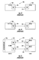
- FIG. 3 is a block diagram of a prior art USB communications system and showing a point-to-point master-slave communication between the USB host or hub as a master and a peripheral USB device as the slave.
- FIG. 4 is a block diagram of a prior art USB communications system and showing how use of the USB On-The-Go addendum to the USB specification allows a standard USB device to reverse the master-slave role with a particular USB hub or become a master for a particular USB device.
- FIG. 5 is a block diagram of a prior art USB communications systems showing three devices in which a USB hub connects two USB devices and communicates between the two devices and controlled by a microcontroller behind the hub.
- FIG. 6 is a high level block diagram of an example of a USB communications system of the present invention and showing a USB device having a processor that includes a USB device controller connected to a PC-hub USB connection and a USB On-The-Go controller operative for a secondary function and having a USB connection to a USB slave device.
- FIG. 7 is a high level block diagram of a USB device controller that can be used in the present invention.
- FIG. 8 is a high level block diagram of a USB On-The-Go device controller that can be used for the present invention.
- FIG. 9 is a high level block diagram showing basic components of the USB device of the present invention.
- FIG. 10 is a schematic, block diagram of a typical On-The-Go USB transceiver that can be modified for use with the present invention.
- the present invention advantageously combines the USB function and the USB One-The-Go function on the same USB device, which includes two USB ports, and controlled by a processor, including a respective USB device controller (USD) and a secondary USB On-The-Go device controller.
- the USB device controller can connect to a USB host.
- the secondary USB On-The-Go device controller can connect to a USB peripheral device and operate as a master, thus, maintaining a high bandwidth, point-to-point connection with a USB slave device.
- the present invention typically does not operate as a USB bridge device that will connect a device to a PC host via a USB bridge.
- the USB device connected to the USB On-The-Go part of the product is not seen from the PC host stack to which the product is connected via the USB port.
- the present invention has several advantages, including a full-speed USB On-The-Go bandwidth function of about 12 Mb/s.
- This USB device provides On-The-Go function and can become a master of almost any secondary USB device, if it is part of a targeted list of peripherals that can be connected to the On-The-Go controller.
- several devices can have several different functionalities and can be switched depending on the application.
- the present invention provides for operation under the USB standard and is especially applicable in the PC-handheld/PDA or smart card market segment.
- the USB device of the present invention also can manage a secondary USB device isolated from the USB tree, and thus, can integrate three devices into one. It also reduces costs because of the USB On-The-Go limited host capability.
- the USB device of the present invention can also isolate a security function and ensure its operation even if it is not connected to a USB host.
- the security function could be removable from the USB device.
- the connection between the USB "slave" device and the USB and On-The-Go device can be done on a printed board. It is not necessary to go through a USB plug and cable. It depends on the application. This can be used also to add functionality to a device very quickly without redeveloping a new device.
- the present invention includes a processor that could be formed as an integrated circuit, for example, a USB microprocessor or microcontroller, including a USB device controller for the PC-hub USB connection, and a USB On-The-Go controller for the USB On-The-Go secondary function and connection operative as a master to a peripheral USB slave device.
- Both the USB and On-The-Go device controllers could be designed to include their own interface block operative with the microcontroller resources and could be optimized depending on the application bandwidth requirements.
- the size of any interface buffer and its accompanying architecture could be varied.
- Any microprocessor, microcontroller, central processing unit or other processor used in the present invention manages communication for the USB device to the USB host as a master and also manages communication at the secondary function, for example, security.
- the embedded software used for the invention could be stored in the memory of the processor, for example a flash, EEPROM, RAM or ROM.
- the USB device controller could include and/or be operative with a USB transceiver.
- the controller would include an analog reception and transmission buffer for the data lines D+, D-, and a logic controller, which could include a serial interface engine (SIE), the logic and state machine for the USB protocol as part of the protocol management, and an interface layer to the application bus, which can be a general purpose peripheral bus of the processor.
- SIE serial interface engine
- the On-The-Go controller could be similar in circuit architecture to the USB controller, but would also include additional circuitry to implement the Session Request Protocol (SRP) and the Host Negotiation Protocol (HNP). Any processor or controller would typically implement some restricted host functions and class drivers, and depending on the On-The-Go controller, would provide these functions in a software stack or hardware state machine to optimize performance.
- SRP Session Request Protocol
- HNP Host Negotiation Protocol
- FIG. 1 For purposes of background and reference, a basic USB data flow between a USB host and a USB device and the various implementations and layers in accordance with Universal Serial Bus specification are set forth in FIG. 1 .
- connection of a host 10 to a physical device 12 requires the interaction between different layers, i.e., the USB bus interface layer 14, USB device layer 16, and function layer 18.
- An interconnect 20 between the host and device is illustrated.
- the USB bus interface layer 14 includes a USB bus interface circuit 22 and serial interface engine (SIE) 24 at the device 12 that communicates with a serial interface engine (SIE) 26 and its host controller 28 at the host 10 via a physical wire 29.
- the USB device layer 16 includes at the physical device 12 a collection of endpoints as a USB logical device 30.
- An endpoint zero 32 is operable in communication via the default pipe 34 to USB system software 36 that is operable for device management at the host 10.
- the function layer 18 includes at the physical device 12 a logical function 38 as an interface collection.
- the interface 40 communicates via a plurality of pipe bundles 44 to client software 42 and is operable for interface management.
- the USB bus interface layer 14 provides the physical wire 29 for the traffic signaling and packet conductivity between the host 10 and physical device 12.
- the USB device layer 16 views the USB system software 36 to perform generic USB operations with the physical device 12 via the default pipe 34 to endpoint zero 32.
- the functional layer 18 adds capabilities to the host using matched client software.
- the USB Device Layer 16 and Function Layer 18 each view logical communications within their layers and use the USB Bus Interface Layer 14 for any data transfer.
- the USB host 10 coordinates the overall USB system, controls access, and monitors the USB topology.
- USB physical devices add functionality to the host and have the same interface. Each physical device carries and reports configuration-related data, which it forwards to the host to allow the host to identify and configure the USB device.
- devices on the USB are connected to a host using a tiered star topology, including the hub.
- the host communicates with each logical device as if it were directly connected to a root port.
- the client software manipulates a USB function interface of a device only as an interface of interest.
- USB host controller driver
- USB driver USB driver
- a software interface between a USB host controller 78 and USB system software 76 implements the host controller driver and allows the host controller to implement functions without requiring the host software to be dependent on any particular implementation.
- One USB driver can support different host controllers. Specific knowledge of a host controller implementation is not required.
- the USB logical device 30 can be considered a collection of endpoints and are grouped into endpoint sets to implement the interface.
- the USB system software 36 manages or controls the device using the default pipe 34 to the endpoint zero 32.
- Client software 42 manages the interface using pipe bundles 44 associated with an endpoint set.
- Data is moved between a buffer on the host 10 and an endpoint on the USB device 12 when client software requests the data.
- the host controller 28 or USB device 12 depending on the direction of data transfer, packetizes the data and forwards the packets over the bus. It also coordinates bus access.
- the host communicates with the physical device using a desired communication that is designed to match any communication requirements of the physical device and transfer characteristics provided by a USB.
- the endpoint is an identifiable portion of the device that terminates the communication between the host. It can be a collection of independent endpoints. Default control uses input and output endpoints and the endpoint number "zero" as part of the default pipe 34.
- the data transport mechanism includes transfers of data between the host controller 28 and the USB system software 36 at the host 10. Buffers can be used as a data transport mechanism between the USB system software 36 and the client software 42 at the host 10.
- the other data transport mechanism includes transactions between the host controller 28 and the serial interface engine 26 within the USB bus interface of the host.
- the data transport mechanism also exists as a data per endpoint between the USB bus interface circuit 22 and the USB logical device 30 at the physical device 12.
- the data transport mechanism between the function 38 (and with the interface 40) and the endpoint zero 32 is interface-specific.
- USB-relevant format of transported data occurs as USB frame data between the serial interface engine 26 and the host controller 28 and between the host controller 28 and the USB system software 36 at the host 10.
- No USB format of transporting data exists between the client software 42 that manages an interface and the USB system software 36.
- USB-relevant format of transported data exists as USB frame data between the USB bus interface circuit 22 and the USB logical device 30. No USB format of data occurs between the interface 40 and the endpoint zero 32 at the device 12.
- USB host and device and data flow can be found in the Universal Serial Bus specification, Chapter 5 entitled, "USB Dataflow Model,” the disclosure which is hereby incorporated by reference in its entirety.
- USB universal serial data bus
- V BUS power line
- a USB smart card upon connection to the system bus, a USB smart card will receive power from the power line V BUS which will cause its processor to initialize and announce its presence so that the host device will recognize the device. This is done by connecting a predetermined voltage (e.g., 3.3 V) as an attachment signal to one or both of the data lines D+, D- via a respective pull-up resistor depending upon the data transfer speed at which the smart card is to operate.
- a predetermined voltage e.g., 3.3 V
- the USB Specification defines three data transfer rates, namely low speed (1.5 Mb/s), full speed (12 Mb/s), and high speed (480 Mb/s).
- USB smart card will send information identifying itself and its capabilities to the host device when prompted.
- This information is incorporated within various descriptors, namely device descriptors, configuration descriptors, interface descriptors, endpoint descriptors, and (optionally) string descriptors. Further information on USB descriptors may be found in the incorporated by reference USB Specification.
- the host device will interpret this data using an appropriate driver and inform the smart card what configurations and system resources it will be allotted during the current session. The smart card uses this information to enumerate itself for use in the system.
- the voltage conditioning circuitry output is selectively coupled to the first output through a resistor responsive to the device being powered by the bus (but not transmitting). This tends to pull up the first output to the voltage level of the voltage source, which makes the smart card capable of being properly detected by the host device upon the bus being driven by a host. Selectively disconnecting the pull-up resistor while the smart card is transmitting or receiving thus results in a more balanced differential output signal. Because the pull-up resistor and voltage conditioning circuitry supplying the proper voltage to the pull-up resistor are an integrated part of the IC, no separate contact is required to supply voltage to the resistor. This permits the smart card to be compatible with the contact configuration of certain existing smart cards, and eliminates the need for the pull-up resistor or voltage conditioning circuitry to be included in the smart card adapter.
- the device may also be detached from the system bus for other reasons.
- the device may be detached to perform a re-enumeration, to conserve power, to reduce communications overhead processing by the host device, or when the V BUS power supply is not within the range specified by the USB
- USB smart card integrated circuits Because of the enhanced functionality afforded by the USB Specification and the significant computing power which may be included in USB smart card integrated circuits, it is possible not only to support multiple applications with a smart card, but also multiple configurations, such as endpoint configurations, for example.
- An example of a USB device which supports two different endpoint configurations is disclosed in U.S. Patent No. 6,122,676 to Brief et al.
- this patent is directed to a USB device, which includes two mappings for relating a received token to an endpoint pipe.
- a host controller selects which of the two mappings the USB device will use during initialization or enumeration, and the host controller can also cause the USB device to change between the two configurations during operation.
- the smart card system 120 is described, including basic components that could be used for the present invention.
- the smart card system is described relative to USB, but the card could be a dual mode smart card operative in both ISO and USB mode.
- the smart card illustratively includes a host device 121 having a communications port 122, a smart card adapter or adapter 123 connected to the communications port and also operable to be connected to another USB peripheral slave device when a smart card is connected.
- a smart card 124 is read by the smart card adapter 123.
- the host device 121 will be a computer of some type, which could be a personal computer (PC), laptop, etc., for example.
- the host device 121 could be any number of computing devices capable of interfacing with a smart card, such as a cable or satellite television receiver/decoder, an automated teller machine (ATM) or other banking machine, a point-of-sale (POS) device (e.g., a cash register), etc., depending upon the given application.
- ATM automated teller machine
- POS point-of-sale
- PDA personal data assistant
- USB or other USB device that is ordinarily a slave to a USB bus master (i.e., host), but when used in a USB On-The-Go (OTG) mode can itself act as a limited USB bus master.
- the smart card would have the added functionality of the USB On-The-Go functionality.
- the port 122 may be a serial communications port connected to the internal system bus of the host device 121 (not shown). In the case of a USB mode, the port 122 will be a USB port, which is also connected to the internal system bus of the host device 121, as will be appreciated by those of skill in the art.
- the smart card system 120 may advantageously be a USB system or a dual mode system which operates in both modes, for example, similar to the system described in U.S. Patent No. 6,439,464 to Fruhauf et al., assigned to the assignee of the present invention, and which is hereby incorporated herein in its entirety by reference. Of course, other suitable smart card formats may also be used, as will be appreciated by those of skill in the art.
- the smart card adapter 123 is of a type compatible with the particular operational protocol being implemented in the system 120 (e.g., a USB type card reader).
- the smart card adapter could be a passive ISO 7816 contact circuit with a fixed USB cable that plugs into a USB port 122.
- multiple readers 123 may be used, as well as multi-purpose readers, which read more than one type of smart card or multi-mode smart cards.
- the card reader 123 can be remotely located with respect to the host device 121, but it need not be. That is, in some embodiments the card reader 123 can be incorporated within the host device 121 or carried by a housing thereof, as will be appreciated by those of skill in the art. Additionally, in some embodiments the smart card adapter 123 may be incorporated into a smart card integrated circuit chip (see below), reducing the "reader” to little more that a "pass through” connector.
- the smart card 124 including On-The-Go functionality illustratively includes a card body 125 and an integrated circuit (IC) 126 carried by the card body. Further, the smart card also illustratively includes contacts 127 for providing an electrical connection between the smart card adapter 123 and the IC 126. Of course, it will be appreciated that in some embodiments the smart card 124 may be wireless and thus not require the contacts 127. In such event, an antenna may be used instead of the contacts 127, for example. Thus, the use of physical contacts 127 on the card body 125 (and corresponding contacts at the card reader 123) will be assumed for purposes of the present discussion.
- the smart card body 125 may be made of various types of materials and take various shapes. Perhaps the most common material used for smart cards is plastic, but other suitable materials may also be used. Moreover, smart cards are also generally rectangular in shape and thin enough to fit in a wallet, similar to a credit card, but again, other shapes and thicknesses may be used.
- the IC 126 may be encased within the card body 125, as illustratively shown, or it may be recessed therein but still exposed. Other mounting configurations are possible, as will be appreciated by those of skill in the art, which are anticipated by the present invention. It should also be noted that the smart card 124 may be incorporated or built into another device as a token or identification circuit therefor, for example.
- the IC 126 illustratively includes two separate transceivers, i.e., a regular USB transceiver 130a, and USB On-The-Go transceiver 130b which are connected to the contacts 127 and sends/receives signals to/from the host device 121 via the smart card adapter 123.
- the first USB transceiver 130a is operative with the processor 131 function of a USB device controller and connects to a USB host, in one example.
- the second transceiver 130b is operative with the processor 131 function of an On-The-Go device controller and connects to USB peripheral 140 as a slave device.
- the transceivers 130a, 130b are controlled by the processor 131, which also performs the various smart card operations.
- buffer circuitry 132 can be included within the IC 126 for buffering signals transmitted between the IC and the host device 121 and/or peripheral slave device 140.
- the memory 133 could include various descriptors and associated USB protocol data and data and protocol management for the On-The-Go functions, including Session Request Protocol (SRP) and the Host Negotiation Protocol (HNP).
- the circuitry could include random access memory (RAM) and non-volatile memory.
- the memory can include various look-up tables. It should be understood, however, that one transceiver could be used capable of working at low speed and/or full speed. For those applications that may use a chip-to-chip without USB cable, the transceiver can be reduced to a simple CMOS buffer input/output with the rise and fall time independent of the speed.
- USB On-The-Go supplement to the USB 2.0 specification allows consumers and/or corporate users to connect mobile devices to each other and/or to various other peripherals.
- the USB On-The-Go supplement gives function to a USB device to overcome the connectivity methods used by different manufacturers including Proprietary Docs, Dongles, Slots, Connectors, and different memory card technologies.
- FIG. 3 is a block diagram of a prior art point-to-point master-slave USB communications system 200, for example, using the USB 2.0 specification.
- the USB host or hub 202 includes a USB port 204 and is typically a personal computer or connected to a personal computer as a master, which in turn can connect up to 128 USB peripheral devices (slaves) 210, via a USB port 212 as shown in FIG. 3 .
- the USB peripheral device 210 has no capability of acting as a master.
- FIG. 4 is an improvement of the system 200 illustrated in FIG. 3 and shows that the USB On-The-Go addendum to the USB specification allows a standard USB device 220 to reverse the master-slave role with a particular USB hub or become a master for a particular USB device 222. Connections are made through the respective USB ports 224, 226.
- USB communications system 230 of in FIG. 5 Another prior art proposal is shown the USB communications system 230 of in FIG. 5 , in which a USB hub 240 includes two USB ports 242, 244 and connects two USB devices 246, 248 through respective USB ports 250, 252. The communication between the two devices 246, 248 is accomplished via the hub 240 and controlled by a microcontroller 256 located behind a hub function. This type of system is expensive.
- the USB On-The-Go specification adds host functionality for connection to USB peripherals and can be adapted for smart card use of the type as explained above.
- the specification details a "dual role device” that can function as a device controller (DC) and/or a host controller (HC).
- the Session Request Protocol (SRP) allows a B-device (as a peripheral) to "nudge” an A-device and "turn-on” the USB Vbus to communicate with each other.
- SRP Session Request Protocol
- HNP Host Negotiation Protocol
- HNP allows either end to switch between a host and slave.
- a mini-A/B connector can allow a mini-A or mini-B connector to plug into one receptacle.
- a dual-role device operative in accordance with the On-The-Go specification allows a device to detect whether a mini-A or mini-B plug is inserted and determine if an ID pin, operative as an extra pin and introduced by the On-The-Go specification, is connected to ground.
- An On-The-Go descriptor from a B-device could describe whether or not the device could handle any Session Request Protocol and/or Host Negotiation Protocol. Any B-device that supports either the Host Negotiation Protocol or Session Request Protocol should be able to respond to the request.
- USB On-The-Go allows two USB devices to communicate in a peer-to-peer connection without requiring the use of a personal computer as a host.
- an On-The-Go dual role device can exchange roles as a host and peripheral.
- the Host Negotiation Protocol could determine how initial roles are determined and why any role reversal necessary. For example, the initial cable orientation could determine initial roles.
- the mini-A plug and mini-B plug and mini-A/B receptacle would add a fifth pin as an ID pin to give different electrical identities to cable ends. This ID pin would be connected to a ground inside the mini-A plug and left floating in the mini-B plug.
- the On-The-Go device receiving a grounded ID pin could be the default A-device (host) and the device with the floating ID pin could be the default B-device (peripheral).
- a printer could be a default host as an A-device and a smart card could be the default peripheral (B-device).
- the smart card may have a printer driver and should act as a USB host to the printer, which contains no driver.
- the Host Negotiation Protocol would allow the roles to be reversed automatically.
- the Session Request Protocol would allow the B-device to request and A-device to turn on the Vbus power and begin a session. This could be defined as the time when the A-device is furnishing Vbus power.
- the A-device could end the session by turning off the Vbus to conserve power in battery powered devices.
- a session request pulse could be generated which would pulse a D+ wire.
- a Vbus wire would wake up the A-device, which would respond either to the D+ or Vbus pulsing as shown in the On-The-Go transceiver block diagram of FIG. 10 and explained in detail below.
- the A-device could detect a pulse to cause it to switch-on the Vbus and start a session.
- the B-device typically would require that a session is not in progress by measuring Vbus and controlling the Vbus pulse to allow the possibility that it might be connected to a traditional USB host.
- FIG. 10 illustrates an On-The-Go transceiver 300, which could be modified for use with the present invention.
- the On-The-Go transceiver could include a dual-role processor 302, for example a microprocessor or Application Specific Integrated Circuit (ASIC), or a digital signal processor (DSP) with USB capability.
- the transceiver includes a switchable pull-up and pull-down resistor circuit 304 on D+/D- to allow peripheral host functionality.
- An ESD circuit 306 is operable with the pull-up resistor switch circuit 304 for electrostatic discharge protection.
- a 5-volt power supply Vcc could be on Vbus and connected through a charge pump circuit 307 and resistor/switch circuit 308 and operable as an A-device and monitor and pulse Vbus as a B-device initiating the Session Request Protocol.
- An ID input pin 310 could be made available as an output to the processor 302 or Application Specific Integrated Circuit.
- the ASIC, DSP or other processor 302 that is connected to a USB transceiver 312.
- the transceiver should be capable of functioning as a peripheral host and switch roles on-the-fly.
- the transceiver circuitry could manage the Vbus pin which also supplies 5-volt power as a host and performs Vbus pulsing as a peripheral. Different switches, including analog switches, could configure the transceiver for the different roles.
- the circuit could include comparators 320, control circuit 322 and regulation circuit 324 as indicated.
- FIG. 6 shows a USB device 400 of the present invention that includes first and second USB ports 402, 404.
- the first port 402 has a USB function.
- the second port has a USB On-The-Go function.
- the first USB port 404 can to be connected to a USB hub 406 and operates in the regular USB master/slave manner.
- the second USB port 404 can be configured and connected to a USB peripheral device 408 and acts as a master to the device 408.
- the processor/controller 410 with appropriate circuitry includes appropriate functions for operation, including any USB device controllers and USB On-The-Go device controllers.
- a USB device controller 420 operable with the present invention is shown in FIG. 7 and includes a USB transceiver 422 that connects to a data interface, for example a D+ and D- connection.
- the device controller includes an analog and transmission buffer 424 for the data lines D+, D-.
- a logic controller 426 includes various functions, typically including a serial interface engine (SIE) 428, which could also be a parallel interface engine (PIE).
- SIE serial interface engine
- PIE parallel interface engine
- the controller 426 includes circuitry for implementing protocol management 430, including and the logic and state machine for the USB protocol.
- An interface control layer 432 can be made to the peripheral or application bus 434 which is usually a general purpose peripheral bus of a microcontroller or CPU.
- FIG. 8 An example of the On-The-Go device controller 440 is shown in FIG. 8 and includes similar components as the USB device controller illustrated in FIG. 7 . Like reference numerals are used to show similar functional components. Additional functional circuitry 442 implements the Session Request Protocol and Host Negotiation Protocol and would implement some restricted host function and host drivers in cooperation with an On-The-Go transceiver 444. The On-The-Go controller 440 could provide these functions in a software stack or hardware state machine to optimize performance. Any processor, including a microcontroller or CPU, could manage communication for the USB device to the USB host/master and manage communication of the secondary function, security, for example. All embedded software could be stored in the processor, which could be flash memory, EEPROM, RAM or ROM.
- FIG. 9 is a high level block diagram of basic components of the USB device that can be used in the present invention and shows the USB device controller 420 and USB On-The-Go controller 440 that are both connected a data interface that includes D+/D- terminals. Both the USB device controller 420 and USB On-The-Go controller 440 connect to the peripheral or application bus 434 that connects to a processor 450 that could be any type of central processing unit, including a microprocessor or microcontroller.
- the memory includes at least RAM 452 and ROM 454 that are operative with the processor as explained before.
Landscapes
- Engineering & Computer Science (AREA)
- Theoretical Computer Science (AREA)
- Physics & Mathematics (AREA)
- General Engineering & Computer Science (AREA)
- General Physics & Mathematics (AREA)
- Information Transfer Systems (AREA)
Description
- The present invention relates to the field of universal serial bus (USB) devices, and, more particularly, to universal serial bus devices adapted for use in USB portable devices or peripherals, including smart cards.
- Smart cards are plastic cards having an embedded Integrated Circuit (IC). That IC may be a logic circuit with its associated memories or a microcontroller with its associated memories and software, or a microcontroller with its associated memories and software coupled to a custom circuit block or interface.
- To use the computing power of the IC, a smart card makes use of a full set of packaging technologies. For example, the die size varies from 1mm2 to 30 mm2, but is limited because of the mechanical limitations imposed by the plastic construction of the smart card. The IC is attached to a lead frame and wire-bonding techniques are used to connect the IC pads to the lead frame contacts. Potting or other strengthening methods can be used to protect the IC against chemical and mechanical stresses during manufacturing and which are a part of everyday usage of a smart card.
- Eight contacts are typically located on one side of the card. The smart card performs transactions with a smart card reader using a serial protocol. The mechanical and electrical specifications for a smart card are published by the International Standard Organization (ISO) as ISO7816-X standards, which have allowed the simple and mass produced magnetic stripe cards to evolve toward the smart card. This natural evolution has allowed smart cards, depending on the IC complexity, of course, to perform pre-paid accounting, cryptographic scheme, personal authentication using a PIN code, biometrics, and java scripts, for example.
- ISO documents ISO 7816-1 Physical Characteristics, ISO 7816-2 Dimensions and Locations of the contacts, ISO 7816-3 Electronic signals and transmission protocols, ISO 7816-4 Interindustry Commands for Interchange, and ISO 7816-10 Electronic signals and answer to reset for synchronous cards are incorporated herein by reference.
- In operation, smart card readers are recognized by the reader infrastructure or a host computer prior to performing any transaction involving a smart card. The infrastructure runs an application involving the smart card. The half duplex protocol between the smart card and the smart card reader, in which either the smart card sends information to the smart card reader or vice versa, cannot start until a smart card is in place and detected by the smart card reader. The infrastructure manages authentication or transactions for pre-paid cards in public telephony, for Bankcards in Point-of-Sale (POS) terminals and Automatic Teller Machines (ATM), for Pay TV providers in set top boxes, and for wireless telecom operators in Subscriber Identification Modules (SIM) used in Global System for Mobile (GSM) terminals. Except for SIM cards, all other smart card reader applications use a physical sensor to detect the smart card. This sensor tells the smart card reader when a smart card is in place, i.e., when the smart card lead frame contacts mate with the smart card reader contacts.
- When the smart card reader has established that a smart card is in place, a power-up sequence begins. After this power-up sequence has finished, the smart card reader typically provides a clock to the smart card and releases a reset signal. The smart card then executes its stored Operating System (OS). The SIM card, on the other hand, is in place only once with the power-off and used constantly subsequent to its positioning.
- The first application for smart card technology was the public telephone system. The smart card die size was typically less than 1mm2, and only memories and logic circuits were integrated in the IC. The smart card reader used all eight contacts to interface properly with the different smart card generations. When the smart card was inserted in the payphone, the telephone infrastructure authenticated the smart card and the telephone removed accounting "units" from the smart card.
- The banking industry subsequently adopted smart cards. The die size was about 10mm2, and a microcontroller and its associated memories and software were integrated in the IC. The smart card reader used up to six contacts to interface properly with the different smart card generations. When a smart card was inserted in the ATM or the POS (point-of-sale), the smart card user was authenticated with a PIN code. The smart card could store different items, such as the balance of cash received from an ATM on a per week basis or details of purchases since a last closing date. Based on this information, authorization could be issued on the spot once the PIN had authenticated the debtor. This was accomplished without telephone calls to the bank.
- Another application for smart cards has been developed by GSM manufacturers. The die size in a SIM is about 30mm2, and a microcontroller and its associated memories and software are integrated in the IC. The SIM reader uses five contacts to interface properly with the smart card. The more sophisticated smart card applications are performed in GSM using Java applets.
- A new market for the smart card has emerged with the growth of the internet accessed from a personal computer. Secure message, Public Key Infrastructure, Authentication and Electronic Payment are new smart card areas of interest. The smart card acts as an e-commerce facilitator. One advantage of a smart card compared to other solutions is the smart card PIN located in its memory that is never communicated in any transaction.
- Presently, a smart card is inserted into a smart card reader connected to a host computer. Two protocols are involved in supporting transactions between the smart card and host computer. The first protocol complies with the ISO-7816-3, which provides detailed requirements for the serial interface between smart card and smart card reader. The reader is connected to the computer via a serial port, a parallel port, or the Universal Serial Bus (USB), using a second protocol. The smart card reader contains electronic circuits and embedded software that enable communication between the smart card using the first protocol and the host computer using the second protocol. The host computer is loaded with any appropriate drivers to support the smart card reader.
- Many countries have begun to use the smart card in the PC environment. The die size used in these applications ranges from 5mm2 to 30mm2, and the microcontroller and its associated memories and software are integrated in the IC typically with a cryptocontroller. Sometimes, a bio-sensor is integrated. The smart card reader uses at least five contacts to interface properly with the smart card in these applications.
- Since the late 1990's, the universal serial bus (USB) has become firmly established and has gained wide acceptance in the PC marketplace. The USB was developed in response to a need for a standard interface that extends the concept of "plug and play" to devices external to a PC. It has enabled users to install and remove external peripheral devices without opening the PC case or removing power from the PC. The USB provides a low-cost, high performance, half-duplex serial interface that is easy to use and readily expandable.
- USB uses four wires. The power supply is carried with two wires (VBUS and ground), and data is carried with the other two wires (D+, D-). Different versions of the USB are available, including the current Universal Serial Bus Specification, Revision 2.0, written and controlled by USB Implementers Forum, Inc., a non-profit corporation founded by the group of companies that developed the USB Specification and is incorporated herein by reference. A previous version is USB specification 1.1, the disclosure which is also incorporated by reference in its entirety. The increasingly widespread use of the USB has led smart card reader manufacturers to develop USB interfaces for connection of their products to host computers to complement the existing serial and parallel interfaces.
- The USB specification has been created to connect up to 128 devices to a USB host or PC with a master-slave communication protocol. USB has many advantages in the "plug and play" arena and enhances ease of use for many devices. USB, however, has not been a replacement for many RS-232 or similar systems. For example, some prior art devices communicate point-to-point to one device and at the same time can be connected to a USB hub by using other serial communication protocols, such as 1394, SPI, or I2C for the point-to-point function. The IEEE 1394 protocol is very expensive compared to USB and I2C is slow for any high bandwidth application. SPI does not have adequate data integrity. It is also possible to use three devices including a USB hub that connects two USB devices and the communication between the devices is accomplished through the hub and controlled by the microcontroller behind the hub function. This is expensive. USB systems are host controlled. If the USB host is switched off, other devices on the system do not work. USB does not support peer-to-peer communications . As a result, one device on a bus must be the host.
- Indeed many portable computing devices, for example, hand-held cellphones and digital cameras, operate as USB peripherals and connect to a personal computer (PC). These USB devices would benefit if they could also connect to other USB devices. The USB On-The-Go addendum to the USB specification allows a standard USB device to reverse the master-slave role with a particular USB hub or become a master for a USB peripheral device. As a result, the USB device functions as both the device controller (DC) and/or a host controller (HC). This protocol is described in the On-The-Go supplement to the USB 2.0 specification revision 1.0 of June 24, 2003, the disclosure which is hereby incorporated by reference in its entirety.
- These devices use the same USB port to be connected to a USB host or USB On-The-Go device. There are products or devices, however, that should be connected to a USB port of a PC at the USB device and at the same time communicate to another master or slave device. This device could be an enabler of the USB device. For example, the device and its secondary function could be an authentication function, an encryption or decryption algorithm for data transfer to the USB bus, or any other secondary function that enables or complements the USB device functionality. A USB On-The-Go device typically has only one USB port to which it can be connected to a USB host or to another USB device.
-
US 2004/0019732 relates to a Universal Serial Bus hub that is operable as a conventional USB hub, and also as a USB On-The-Go hub for connecting USB-OTG compliant devices when a host device is not present. - It is therefore an object of the present invention to provide a USB device that overcomes the disadvantages of the arm as set forth above and can connect at the same time to a USB host and to a peripheral USB device and operate in a secondary USB On-The-Go function to provide a high bandwidth point-to-point connection with a USB slave device.
- In accordance with the present invention, a USB device includes a data interface operable as first and second communications ports, for example, USB ports. A processor is operable for configuring the first communications port for connecting to a USB host and simultaneously configuring the second communications port for connecting to a USB slave device in accordance with the USB On-The-Go specification. In the present claimed invention, the processor could be formed as an integrated circuit with microprocessor or microcontroller functions, and include other functions of a USB device controller and a secondary USB On-The-Go device controller for creating a point-to-point connection with the USE slave device.
- In another embodiment of the present invention, the processor is operative for implementing the Session Request Protocol (SRP) and requesting a USB device to begin a communication session. It can request a USB device to begin a communications session using this protocol by one of at least data-line-pulsing and Vbus pulsing. The processor is also operative for implementing the Host Negotiation Protocol (HNP) for transferring control from a default host to a default peripheral USB device.
- In yet another embodiment of the present invention, a memory stores a program operative for managing communications to the first communications port to a USB host and managing communications through the second communications port as a secondary function in accordance with the USB On-The-Go specification. This memory could be a flash memory, EEPROM, RAM or ROM memory, as non-limiting examples.
- An integrated circuit for USB device is also disclosed and includes the data interface, USB transceiver and USB On-The-Go transceiver connected to the data interface. A processor is formed integral with integrated circuit and operable for configuring the USB transceiver and data interface for connecting to a USB host and configuring the On-The-Go transceiver and data interface as a USB master connecting to a USB slave device.
- A smart card is also disclosed. It includes a smart card body and contacts carried by the smart card body. An integrated circuit is carried by the smart card body and comprises a data interface operable with the contacts. A USB transceiver and USB On-The-Go transceiver are connected to the data interface. The processor is operable for configuring the USB transceiver and data interface for connecting to a USB host and configuring the On-The-Go transceiver and data interface as a USB master connecting to a USB slave device.
- A method is also disclosed in accordance with the present invention.
- Other objects, features and advantages of the present invention will become apparent from the detailed description of the invention which follows, when considered in light of the accompanying drawings in which:
-
FIG. 1 is a block diagram of a USB host/device showing various transport mechanisms, pipes and the USB relevant format of transported data between the host and interconnected physical device as used in the universal serial bus specification. -
FIG. 2 is a schematic block diagram of a smart card system that can be modified for use with the present invention. -
FIG. 3 is a block diagram of a prior art USB communications system and showing a point-to-point master-slave communication between the USB host or hub as a master and a peripheral USB device as the slave. -
FIG. 4 is a block diagram of a prior art USB communications system and showing how use of the USB On-The-Go addendum to the USB specification allows a standard USB device to reverse the master-slave role with a particular USB hub or become a master for a particular USB device. -
FIG. 5 is a block diagram of a prior art USB communications systems showing three devices in which a USB hub connects two USB devices and communicates between the two devices and controlled by a microcontroller behind the hub. -
FIG. 6 is a high level block diagram of an example of a USB communications system of the present invention and showing a USB device having a processor that includes a USB device controller connected to a PC-hub USB connection and a USB On-The-Go controller operative for a secondary function and having a USB connection to a USB slave device. -
FIG. 7 is a high level block diagram of a USB device controller that can be used in the present invention. -
FIG. 8 is a high level block diagram of a USB On-The-Go device controller that can be used for the present invention. -
FIG. 9 is a high level block diagram showing basic components of the USB device of the present invention. -
FIG. 10 is a schematic, block diagram of a typical On-The-Go USB transceiver that can be modified for use with the present invention. - The present invention will now be described more fully hereinafter with reference to the accompanying drawings, in which preferred embodiments of the invention are shown. This invention may, however, be embodied in many different forms and should not be construed as limited to the embodiments set forth herein. Rather, these embodiments are provided so that this disclosure will be thorough and complete, and will fully convey the scope of the invention to those skilled in the art. Like numbers refer to like elements throughout, and prime notation is used to indicate similar elements in alternative embodiments.
- The present invention advantageously combines the USB function and the USB One-The-Go function on the same USB device, which includes two USB ports, and controlled by a processor, including a respective USB device controller (USD) and a secondary USB On-The-Go device controller. The USB device controller can connect to a USB host. The secondary USB On-The-Go device controller can connect to a USB peripheral device and operate as a master, thus, maintaining a high bandwidth, point-to-point connection with a USB slave device. It should be understood that the present invention typically does not operate as a USB bridge device that will connect a device to a PC host via a USB bridge. The USB device connected to the USB On-The-Go part of the product is not seen from the PC host stack to which the product is connected via the USB port.
- The present invention has several advantages, including a full-speed USB On-The-Go bandwidth function of about 12 Mb/s. This USB device provides On-The-Go function and can become a master of almost any secondary USB device, if it is part of a targeted list of peripherals that can be connected to the On-The-Go controller. Among the same class of devices, several devices can have several different functionalities and can be switched depending on the application. The present invention provides for operation under the USB standard and is especially applicable in the PC-handheld/PDA or smart card market segment. The USB device of the present invention also can manage a secondary USB device isolated from the USB tree, and thus, can integrate three devices into one. It also reduces costs because of the USB On-The-Go limited host capability. The USB device of the present invention can also isolate a security function and ensure its operation even if it is not connected to a USB host. The security function could be removable from the USB device. The connection between the USB "slave" device and the USB and On-The-Go device can be done on a printed board. It is not necessary to go through a USB plug and cable. It depends on the application. This can be used also to add functionality to a device very quickly without redeveloping a new device.
- The present invention includes a processor that could be formed as an integrated circuit, for example, a USB microprocessor or microcontroller, including a USB device controller for the PC-hub USB connection, and a USB On-The-Go controller for the USB On-The-Go secondary function and connection operative as a master to a peripheral USB slave device. Both the USB and On-The-Go device controllers could be designed to include their own interface block operative with the microcontroller resources and could be optimized depending on the application bandwidth requirements. The size of any interface buffer and its accompanying architecture could be varied. Any microprocessor, microcontroller, central processing unit or other processor used in the present invention manages communication for the USB device to the USB host as a master and also manages communication at the secondary function, for example, security. The embedded software used for the invention could be stored in the memory of the processor, for example a flash, EEPROM, RAM or ROM.
- The USB device controller could include and/or be operative with a USB transceiver. The controller would include an analog reception and transmission buffer for the data lines D+, D-, and a logic controller, which could include a serial interface engine (SIE), the logic and state machine for the USB protocol as part of the protocol management, and an interface layer to the application bus, which can be a general purpose peripheral bus of the processor. The On-The-Go controller could be similar in circuit architecture to the USB controller, but would also include additional circuitry to implement the Session Request Protocol (SRP) and the Host Negotiation Protocol (HNP). Any processor or controller would typically implement some restricted host functions and class drivers, and depending on the On-The-Go controller, would provide these functions in a software stack or hardware state machine to optimize performance.
- For purposes of background and reference, a basic USB data flow between a USB host and a USB device and the various implementations and layers in accordance with Universal Serial Bus specification are set forth in
FIG. 1 . - As shown in
FIG. 1 , the connection of ahost 10 to aphysical device 12 requires the interaction between different layers, i.e., the USBbus interface layer 14, USB device layer 16, andfunction layer 18. Aninterconnect 20 between the host and device is illustrated. - The USB
bus interface layer 14 includes a USBbus interface circuit 22 and serial interface engine (SIE) 24 at thedevice 12 that communicates with a serial interface engine (SIE) 26 and itshost controller 28 at thehost 10 via aphysical wire 29. The USB device layer 16 includes at the physical device 12 a collection of endpoints as a USBlogical device 30. An endpoint zero 32 is operable in communication via thedefault pipe 34 toUSB system software 36 that is operable for device management at thehost 10. Thefunction layer 18 includes at the physical device 12 alogical function 38 as an interface collection. Theinterface 40 communicates via a plurality of pipe bundles 44 toclient software 42 and is operable for interface management. - The USB
bus interface layer 14 provides thephysical wire 29 for the traffic signaling and packet conductivity between thehost 10 andphysical device 12. The USB device layer 16 views theUSB system software 36 to perform generic USB operations with thephysical device 12 via thedefault pipe 34 to endpoint zero 32. Thefunctional layer 18 adds capabilities to the host using matched client software. The USB Device Layer 16 andFunction Layer 18 each view logical communications within their layers and use the USBBus Interface Layer 14 for any data transfer. TheUSB host 10 coordinates the overall USB system, controls access, and monitors the USB topology. - Logical communications exist between the client software and the
Function Layer 18 and theUSB system software 36 and USBlogical device 30. Actual packets flow between theUSB host controller 28 and the USBbus interface circuit 22. - As is known, USB physical devices add functionality to the host and have the same interface. Each physical device carries and reports configuration-related data, which it forwards to the host to allow the host to identify and configure the USB device. Typically, devices on the USB are connected to a host using a tiered star topology, including the hub. The host, on the other hand, communicates with each logical device as if it were directly connected to a root port. The client software manipulates a USB function interface of a device only as an interface of interest.
- It should be understood that the actual communication flows across several interface boundaries. The two software interfaces for the host are a host controller driver (HCD) and a USB driver (USBD). A software interface between a USB host controller 78 and USB system software 76 implements the host controller driver and allows the host controller to implement functions without requiring the host software to be dependent on any particular implementation. One USB driver can support different host controllers. Specific knowledge of a host controller implementation is not required.
- The USB
logical device 30 can be considered a collection of endpoints and are grouped into endpoint sets to implement the interface. TheUSB system software 36 manages or controls the device using thedefault pipe 34 to the endpoint zero 32.Client software 42 manages the interface usingpipe bundles 44 associated with an endpoint set. Data is moved between a buffer on thehost 10 and an endpoint on theUSB device 12 when client software requests the data. Thehost controller 28 orUSB device 12, depending on the direction of data transfer, packetizes the data and forwards the packets over the bus. It also coordinates bus access. The host communicates with the physical device using a desired communication that is designed to match any communication requirements of the physical device and transfer characteristics provided by a USB. - The endpoint is an identifiable portion of the device that terminates the communication between the host. It can be a collection of independent endpoints. Default control uses input and output endpoints and the endpoint number "zero" as part of the
default pipe 34. - The data transport mechanism includes transfers of data between the
host controller 28 and theUSB system software 36 at thehost 10. Buffers can be used as a data transport mechanism between theUSB system software 36 and theclient software 42 at thehost 10. The other data transport mechanism includes transactions between thehost controller 28 and the serial interface engine 26 within the USB bus interface of the host. - The data transport mechanism also exists as a data per endpoint between the USB
bus interface circuit 22 and the USBlogical device 30 at thephysical device 12. The data transport mechanism between the function 38 (and with the interface 40) and the endpoint zero 32 is interface-specific. - USB-relevant format of transported data occurs as USB frame data between the serial interface engine 26 and the
host controller 28 and between thehost controller 28 and theUSB system software 36 at thehost 10. No USB format of transporting data exists between theclient software 42 that manages an interface and theUSB system software 36. - At the
device 12, USB-relevant format of transported data exists as USB frame data between the USBbus interface circuit 22 and the USBlogical device 30. No USB format of data occurs between theinterface 40 and the endpoint zero 32 at thedevice 12. - Further details of the functioning of the USB host and device and data flow can be found in the Universal Serial Bus specification, Chapter 5 entitled, "USB Dataflow Model," the disclosure which is hereby incorporated by reference in its entirety.
- There now follows a brief description of using USB with a generic smart card device to enhance understanding of the present invention when used with a smart card. In accordance with the USB Specification, the host device operates as the master of the system bus, and all of the USB devices connected to the system bus operate as slave devices. A USB system bus includes two data lines D+ and D-, over which differential serial data signals are transmitted. Moreover, the USB system bus also includes a power line VBUS which may be used to provide an operating voltage from the host device to USB devices without their own source of power, as well as a ground line.
- Accordingly, upon connection to the system bus, a USB smart card will receive power from the power line VBUS which will cause its processor to initialize and announce its presence so that the host device will recognize the device. This is done by connecting a predetermined voltage (e.g., 3.3 V) as an attachment signal to one or both of the data lines D+, D- via a respective pull-up resistor depending upon the data transfer speed at which the smart card is to operate. In particular, the USB Specification defines three data transfer rates, namely low speed (1.5 Mb/s), full speed (12 Mb/s), and high speed (480 Mb/s).
- Generally speaking, once the USB smart card is recognized by the host device, the smart card will send information identifying itself and its capabilities to the host device when prompted. This information is incorporated within various descriptors, namely device descriptors, configuration descriptors, interface descriptors, endpoint descriptors, and (optionally) string descriptors. Further information on USB descriptors may be found in the incorporated by reference USB Specification. The host device will interpret this data using an appropriate driver and inform the smart card what configurations and system resources it will be allotted during the current session. The smart card uses this information to enumerate itself for use in the system.
- One particularly advantageous approach for managing pull-up connections to differential data lines is disclosed in U.S. Application Serial No. 2002/0066791 to Leydier et al., and which is hereby incorporated herein in its entirety by reference. In particular, this application is directed to a smart card which has an IC with voltage conditioning circuitry and a pull-up resistor. The smart card, when inserted in a smart card adapter coupled to a host device, is capable of signaling the host device over a bus using the integrated pull-up resistor selectively coupled to a voltage output of the voltage conditioning circuitry and a first output of the smart card.
- The voltage conditioning circuitry output is selectively coupled to the first output through a resistor responsive to the device being powered by the bus (but not transmitting). This tends to pull up the first output to the voltage level of the voltage source, which makes the smart card capable of being properly detected by the host device upon the bus being driven by a host. Selectively disconnecting the pull-up resistor while the smart card is transmitting or receiving thus results in a more balanced differential output signal. Because the pull-up resistor and voltage conditioning circuitry supplying the proper voltage to the pull-up resistor are an integrated part of the IC, no separate contact is required to supply voltage to the resistor. This permits the smart card to be compatible with the contact configuration of certain existing smart cards, and eliminates the need for the pull-up resistor or voltage conditioning circuitry to be included in the smart card adapter.
- Moreover, the device may also be detached from the system bus for other reasons. For example, the device may be detached to perform a re-enumeration, to conserve power, to reduce communications overhead processing by the host device, or when the VBUS power supply is not within the range specified by the USB
- Because of the enhanced functionality afforded by the USB Specification and the significant computing power which may be included in USB smart card integrated circuits, it is possible not only to support multiple applications with a smart card, but also multiple configurations, such as endpoint configurations, for example. An example of a USB device which supports two different endpoint configurations is disclosed in
U.S. Patent No. 6,122,676 to Brief et al. In particular, this patent is directed to a USB device, which includes two mappings for relating a received token to an endpoint pipe. A host controller selects which of the two mappings the USB device will use during initialization or enumeration, and the host controller can also cause the USB device to change between the two configurations during operation. - Referring now to
FIG. 2 , asmart card system 120 is described, including basic components that could be used for the present invention. The smart card system is described relative to USB, but the card could be a dual mode smart card operative in both ISO and USB mode. The smart card illustratively includes ahost device 121 having acommunications port 122, a smart card adapter oradapter 123 connected to the communications port and also operable to be connected to another USB peripheral slave device when a smart card is connected. Asmart card 124 is read by thesmart card adapter 123. Generally speaking, thehost device 121 will be a computer of some type, which could be a personal computer (PC), laptop, etc., for example. - Of course, smart card systems take many forms, so the
host device 121 could be any number of computing devices capable of interfacing with a smart card, such as a cable or satellite television receiver/decoder, an automated teller machine (ATM) or other banking machine, a point-of-sale (POS) device (e.g., a cash register), etc., depending upon the given application. Another example would be a personal data assistant (PDA) or other USB device that is ordinarily a slave to a USB bus master (i.e., host), but when used in a USB On-The-Go (OTG) mode can itself act as a limited USB bus master. Of course, in the present invention, the smart card would have the added functionality of the USB On-The-Go functionality. - In an ISO 7816 mode, the
port 122 may be a serial communications port connected to the internal system bus of the host device 121 (not shown). In the case of a USB mode, theport 122 will be a USB port, which is also connected to the internal system bus of thehost device 121, as will be appreciated by those of skill in the art. Thesmart card system 120 may advantageously be a USB system or a dual mode system which operates in both modes, for example, similar to the system described inU.S. Patent No. 6,439,464 to Fruhauf et al., assigned to the assignee of the present invention, and which is hereby incorporated herein in its entirety by reference. Of course, other suitable smart card formats may also be used, as will be appreciated by those of skill in the art. - The
smart card adapter 123 is of a type compatible with the particular operational protocol being implemented in the system 120 (e.g., a USB type card reader). The smart card adapter could be a passive ISO 7816 contact circuit with a fixed USB cable that plugs into aUSB port 122. Of course,multiple readers 123 may be used, as well as multi-purpose readers, which read more than one type of smart card or multi-mode smart cards. In addition, thecard reader 123 can be remotely located with respect to thehost device 121, but it need not be. That is, in some embodiments thecard reader 123 can be incorporated within thehost device 121 or carried by a housing thereof, as will be appreciated by those of skill in the art. Additionally, in some embodiments thesmart card adapter 123 may be incorporated into a smart card integrated circuit chip (see below), reducing the "reader" to little more that a "pass through" connector. - The
smart card 124 including On-The-Go functionality illustratively includes acard body 125 and an integrated circuit (IC) 126 carried by the card body. Further, the smart card also illustratively includescontacts 127 for providing an electrical connection between thesmart card adapter 123 and theIC 126. Of course, it will be appreciated that in some embodiments thesmart card 124 may be wireless and thus not require thecontacts 127. In such event, an antenna may be used instead of thecontacts 127, for example. Thus, the use ofphysical contacts 127 on the card body 125 (and corresponding contacts at the card reader 123) will be assumed for purposes of the present discussion. - It should be noted that the
smart card body 125 may be made of various types of materials and take various shapes. Perhaps the most common material used for smart cards is plastic, but other suitable materials may also be used. Moreover, smart cards are also generally rectangular in shape and thin enough to fit in a wallet, similar to a credit card, but again, other shapes and thicknesses may be used. TheIC 126 may be encased within thecard body 125, as illustratively shown, or it may be recessed therein but still exposed. Other mounting configurations are possible, as will be appreciated by those of skill in the art, which are anticipated by the present invention. It should also be noted that thesmart card 124 may be incorporated or built into another device as a token or identification circuit therefor, for example. - More particularly, the
IC 126 illustratively includes two separate transceivers, i.e., aregular USB transceiver 130a, and USB On-The-Go transceiver 130b which are connected to thecontacts 127 and sends/receives signals to/from thehost device 121 via thesmart card adapter 123. Thefirst USB transceiver 130a is operative with theprocessor 131 function of a USB device controller and connects to a USB host, in one example. Thesecond transceiver 130b is operative with theprocessor 131 function of an On-The-Go device controller and connects to USB peripheral 140 as a slave device. Thetransceivers processor 131, which also performs the various smart card operations. - Furthermore,
buffer circuitry 132 can be included within theIC 126 for buffering signals transmitted between the IC and thehost device 121 and/orperipheral slave device 140. There are two USB ports for this device. In the case of a smart card, the first port is connected to 123 with theinterface 127. The second port is connected directly to thedevice 140. Both 140 and 125 could be in the same micromodule like a multi-chip package, or connected through a second smart card interface like 127. Thememory 133 could include various descriptors and associated USB protocol data and data and protocol management for the On-The-Go functions, including Session Request Protocol (SRP) and the Host Negotiation Protocol (HNP). The circuitry could include random access memory (RAM) and non-volatile memory. The memory can include various look-up tables. It should be understood, however, that one transceiver could be used capable of working at low speed and/or full speed. For those applications that may use a chip-to-chip without USB cable, the transceiver can be reduced to a simple CMOS buffer input/output with the rise and fall time independent of the speed. - The USB On-The-Go supplement to the USB 2.0 specification allows consumers and/or corporate users to connect mobile devices to each other and/or to various other peripherals. The USB On-The-Go supplement gives function to a USB device to overcome the connectivity methods used by different manufacturers including Proprietary Docs, Dongles, Slots, Connectors, and different memory card technologies.
- The drawbacks of existing systems are shown in
FIGS. 3-5. FIG. 3 is a block diagram of a prior art point-to-point master-slaveUSB communications system 200, for example, using the USB 2.0 specification. The USB host orhub 202 includes aUSB port 204 and is typically a personal computer or connected to a personal computer as a master, which in turn can connect up to 128 USB peripheral devices (slaves) 210, via aUSB port 212 as shown inFIG. 3 . The USBperipheral device 210 has no capability of acting as a master. -
FIG. 4 is an improvement of thesystem 200 illustrated inFIG. 3 and shows that the USB On-The-Go addendum to the USB specification allows astandard USB device 220 to reverse the master-slave role with a particular USB hub or become a master for aparticular USB device 222. Connections are made through therespective USB ports - Another prior art proposal is shown the
USB communications system 230 of inFIG. 5 , in which aUSB hub 240 includes twoUSB ports USB devices respective USB ports devices hub 240 and controlled by amicrocontroller 256 located behind a hub function. This type of system is expensive. - The USB On-The-Go specification adds host functionality for connection to USB peripherals and can be adapted for smart card use of the type as explained above. The specification details a "dual role device" that can function as a device controller (DC) and/or a host controller (HC). The Session Request Protocol (SRP) allows a B-device (as a peripheral) to "nudge" an A-device and "turn-on" the USB Vbus to communicate with each other. The Host Negotiation Protocol (HNP), on the other hand, allows either end to switch between a host and slave.
- Different types of connectors can be used for upstream and downstream ports. A mini-A/B connector can allow a mini-A or mini-B connector to plug into one receptacle. A dual-role device operative in accordance with the On-The-Go specification allows a device to detect whether a mini-A or mini-B plug is inserted and determine if an ID pin, operative as an extra pin and introduced by the On-The-Go specification, is connected to ground. An On-The-Go descriptor from a B-device could describe whether or not the device could handle any Session Request Protocol and/or Host Negotiation Protocol. Any B-device that supports either the Host Negotiation Protocol or Session Request Protocol should be able to respond to the request.
- It is evident that the USB On-The-Go specification allows two USB devices to communicate in a peer-to-peer connection without requiring the use of a personal computer as a host. As noted before, an On-The-Go dual role device can exchange roles as a host and peripheral. The Host Negotiation Protocol could determine how initial roles are determined and why any role reversal necessary. For example, the initial cable orientation could determine initial roles. The mini-A plug and mini-B plug and mini-A/B receptacle would add a fifth pin as an ID pin to give different electrical identities to cable ends. This ID pin would be connected to a ground inside the mini-A plug and left floating in the mini-B plug. The On-The-Go device receiving a grounded ID pin could be the default A-device (host) and the device with the floating ID pin could be the default B-device (peripheral). For example, a printer could be a default host as an A-device and a smart card could be the default peripheral (B-device). The smart card may have a printer driver and should act as a USB host to the printer, which contains no driver. Thus, instead of requiring the user to reverse the cable, the Host Negotiation Protocol would allow the roles to be reversed automatically. The Session Request Protocol would allow the B-device to request and A-device to turn on the Vbus power and begin a session. This could be defined as the time when the A-device is furnishing Vbus power.
- The A-device could end the session by turning off the Vbus to conserve power in battery powered devices. A session request pulse could be generated which would pulse a D+ wire. A Vbus wire would wake up the A-device, which would respond either to the D+ or Vbus pulsing as shown in the On-The-Go transceiver block diagram of
FIG. 10 and explained in detail below. The A-device could detect a pulse to cause it to switch-on the Vbus and start a session. The B-device typically would require that a session is not in progress by measuring Vbus and controlling the Vbus pulse to allow the possibility that it might be connected to a traditional USB host. -
FIG. 10 illustrates an On-The-Go transceiver 300, which could be modified for use with the present invention. The On-The-Go transceiver could include a dual-role processor 302, for example a microprocessor or Application Specific Integrated Circuit (ASIC), or a digital signal processor (DSP) with USB capability. The transceiver includes a switchable pull-up and pull-down resistor circuit 304 on D+/D- to allow peripheral host functionality. AnESD circuit 306 is operable with the pull-upresistor switch circuit 304 for electrostatic discharge protection. A 5-volt power supply Vcc could be on Vbus and connected through a charge pump circuit 307 and resistor/switch circuit 308 and operable as an A-device and monitor and pulse Vbus as a B-device initiating the Session Request Protocol. - An
ID input pin 310 could be made available as an output to theprocessor 302 or Application Specific Integrated Circuit. The ASIC, DSP orother processor 302 that is connected to aUSB transceiver 312. The transceiver should be capable of functioning as a peripheral host and switch roles on-the-fly. The transceiver circuitry could manage the Vbus pin which also supplies 5-volt power as a host and performs Vbus pulsing as a peripheral. Different switches, including analog switches, could configure the transceiver for the different roles. The circuit could includecomparators 320,control circuit 322 andregulation circuit 324 as indicated. - In accordance with the present invention,
FIG. 6 shows aUSB device 400 of the present invention that includes first andsecond USB ports first port 402 has a USB function. The second port has a USB On-The-Go function. Thefirst USB port 404 can to be connected to aUSB hub 406 and operates in the regular USB master/slave manner. Thesecond USB port 404 can be configured and connected to a USBperipheral device 408 and acts as a master to thedevice 408. The processor/controller 410 with appropriate circuitry includes appropriate functions for operation, including any USB device controllers and USB On-The-Go device controllers. - A
USB device controller 420 operable with the present invention is shown inFIG. 7 and includes aUSB transceiver 422 that connects to a data interface, for example a D+ and D- connection. The device controller includes an analog andtransmission buffer 424 for the data lines D+, D-. Alogic controller 426 includes various functions, typically including a serial interface engine (SIE) 428, which could also be a parallel interface engine (PIE). Thecontroller 426 includes circuitry for implementingprotocol management 430, including and the logic and state machine for the USB protocol. Aninterface control layer 432 can be made to the peripheral orapplication bus 434 which is usually a general purpose peripheral bus of a microcontroller or CPU. - An example of the On-The-
Go device controller 440 is shown inFIG. 8 and includes similar components as the USB device controller illustrated inFIG. 7 . Like reference numerals are used to show similar functional components. Additionalfunctional circuitry 442 implements the Session Request Protocol and Host Negotiation Protocol and would implement some restricted host function and host drivers in cooperation with an On-The-Go transceiver 444. The On-The-Go controller 440 could provide these functions in a software stack or hardware state machine to optimize performance. Any processor, including a microcontroller or CPU, could manage communication for the USB device to the USB host/master and manage communication of the secondary function, security, for example. All embedded software could be stored in the processor, which could be flash memory, EEPROM, RAM or ROM. -
FIG. 9 is a high level block diagram of basic components of the USB device that can be used in the present invention and shows theUSB device controller 420 and USB On-The-Go controller 440 that are both connected a data interface that includes D+/D- terminals. Both theUSB device controller 420 and USB On-The-Go controller 440 connect to the peripheral orapplication bus 434 that connects to aprocessor 450 that could be any type of central processing unit, including a microprocessor or microcontroller. The memory includes atleast RAM 452 andROM 454 that are operative with the processor as explained before. - Many modifications and other embodiments of the invention will come to the mind of one skilled in the art having the benefit of the teachings presented in the foregoing descriptions and the associated drawings. Therefore, it is understood that the invention is not to be limited to the specific embodiments disclosed, and that modifications and embodiments are intended to be included within the scope of the appended claims.
Claims (17)
- A USB device (400) comprising:first (402) and seconds (404) communications ports; anda processor (410) operable for configuring the first communications port (402) for connecting to a USB host (406) and configuring the second communications port (404) as a USB master for connecting to a USB slave device (408); characterized in further comprisinga memory (452, 454) for storing a program operative for managing communications through the first USB port (402) to a USB host (406) and simultaneously managing communications through the second USB port (404) as a secondary function in accordance with the USB On-The-Go specification.
- A USB device (400) according to Claim 1, wherein said processor (410) comprises a USB device controller operatively connected to the first communications port (402) and a USB On-The-Go device controller operatively connected to second communications port (404) for creating a point-to-point connection with a USB slave device (408).
- A USB device (400) according to Claim 1 or 2, wherein said processor comprises a microcontroller.
- A USB device (400) according to claim 2 or 3:wherein said first and second communications ports comprise first and second USB ports;said USB device controller further comprising a USB transceiver (422) and logic controller; andsaid USB On-The-Go device controller (440) comprising a USB On-The-Go transceiver (444), a logic controller, and circuitry for implementing a USB On-The-Go protocol.
- An integrated circuit for the USB device (400) of claim 1, comprising:a data interface operable as the first and second communications ports;a USB transceiver (422) and USB On-The-Go transceiver (444) connected to the data interface; andsaid processor (410) operable for configuring the USB transceiver and data interface for connecting to a USB host (406) and simultaneously configuring the On-The-Go transceiver and data interface as a USB master for connecting to a USB slave device (408).
- A smart card (124) comprising the integrated circuit of claim 5, and further comprising:a smart card body (125);contacts (127) carried by the smart card body (125); andwherein said integrated circuit (126) is carried by the smart card body (125) and wherein said data interface is operable with the contacts.
- A device or a circuit or a smart card according to Claim 1, 5, 6 or any claim appended thereto, wherein said processor (410) comprises a USB device controller and a secondary USB On-The-Go device controller for creating a point-to-point connection with a USB slave device (408).
- A device or a circuit or a smart card according to any preceding Claim, wherein said processor (410) or the USB On-The-Go device controller is operative for implementing the Session Request Protocol (SRP) and requesting a USB device to begin a session.
- A device or a circuit or a smart card according to any preceding Claim, wherein said processor (410) or the USB On-The-Go device controller is operative for requesting a USB device to begin a session by one of at least data-line pulsing and Vbus pulsing.
- A device or a circuit or a smart card according to any preceding Claim, wherein said USB On-The-Go device controller or processor is operative for implementing the Host Negotiation Protocol for transferring control from a default Host to a default peripheral USB device.
- A device or a circuit or a smart card according to any preceding Claim, and further comprising a memory for storing a program operative for managing communications through the data interface to a USB host and managing communications through the data interface as a secondary function in accordance with the USB On-The-Go specification.
- A device or circuit or a smart card according to Claim 11, wherein said memory comprises a Flash, EEPROM, RAM or ROM memory.
- A method for operating a USB device (400) comprising
configuring a first USB port (402) for connecting to a USB host (406) and simultaneously configuring a second USB port (404) as a USB master for connecting to a USB slave device (408) in accordance with the USB On-The-Go specification; characterized in that
storing a program operative for managing communications through the first USB port (402) to a USB host (406) and simultaneously managing communications through the second USB port (404) as on secondary function in accordance with the USB On-The-Go specification. - A method according to Claim 13, which further comprises creating a point-to-point connection with a USB slave device (408).
- A method according to Claim 13 or 14, which further comprises implementing the Session Request Protocol (SRP) and requesting a device to begin a session.
- A method according to Claim 13, 14 or 15, which further comprises requesting a device to begin a session by one of at least data-line pulsing and Vbus pulsing.
- A method according to Claim 13, 14, 15, or 16, which further comprises implementing the Host Negotiation Protocol for transferring control from a default Host to a default peripheral device.
Applications Claiming Priority (1)
| Application Number | Priority Date | Filing Date | Title |
|---|---|---|---|
| US10/954,777 US7413129B2 (en) | 2004-09-30 | 2004-09-30 | USB device with secondary USB on-the-go function |
Publications (3)
| Publication Number | Publication Date |
|---|---|
| EP1643372A2 EP1643372A2 (en) | 2006-04-05 |
| EP1643372A3 EP1643372A3 (en) | 2006-04-19 |
| EP1643372B1 true EP1643372B1 (en) | 2011-03-09 |
Family
ID=35608869
Family Applications (1)
| Application Number | Title | Priority Date | Filing Date |
|---|---|---|---|
| EP05255985A Not-in-force EP1643372B1 (en) | 2004-09-30 | 2005-09-26 | USB device with secondary USB on-the-go function |
Country Status (3)
| Country | Link |
|---|---|
| US (1) | US7413129B2 (en) |
| EP (1) | EP1643372B1 (en) |
| DE (1) | DE602005026761D1 (en) |
Families Citing this family (86)
| Publication number | Priority date | Publication date | Assignee | Title |
|---|---|---|---|---|
| US8625270B2 (en) | 1999-08-04 | 2014-01-07 | Super Talent Technology, Corp. | USB flash drive with deploying and retracting functionalities using retractable cover/cap |
| US7744387B2 (en) * | 1999-08-04 | 2010-06-29 | Super Talent Electronics, Inc. | Multi-level cell (MLC) rotate flash memory device |
| US20080071973A1 (en) * | 2000-01-06 | 2008-03-20 | Chow David Q | Electronic data flash card with various flash memory cells |
| US7984303B1 (en) | 2000-01-06 | 2011-07-19 | Super Talent Electronics, Inc. | Flash memory devices with security features |
| US7628622B2 (en) * | 1999-08-04 | 2009-12-08 | Super Talent Electronics, Inc. | Multi-level cell (MLC) slide flash memory |
| US8102662B2 (en) * | 2007-07-05 | 2012-01-24 | Super Talent Electronics, Inc. | USB package with bistable sliding mechanism |
| US8078794B2 (en) * | 2000-01-06 | 2011-12-13 | Super Talent Electronics, Inc. | Hybrid SSD using a combination of SLC and MLC flash memory arrays |
| US8073985B1 (en) | 2004-02-12 | 2011-12-06 | Super Talent Electronics, Inc. | Backward compatible extended USB plug and receptacle with dual personality |
| US8043099B1 (en) | 2004-02-12 | 2011-10-25 | Super Talent Electronics, Inc. | Extended USB plug, USB PCBA, and USB flash drive with dual-personality |
| US20080082813A1 (en) * | 2000-01-06 | 2008-04-03 | Chow David Q | Portable usb device that boots a computer as a server with security measure |
| US7788553B2 (en) * | 2000-01-06 | 2010-08-31 | Super Talent Electronics, Inc. | Mass production testing of USB flash cards with various flash memory cells |
| US8240034B1 (en) | 2000-01-06 | 2012-08-14 | Super Talent Electronics, Inc. | High throughput manufacturing method for micro flash memory cards |
| US7930531B2 (en) * | 2000-01-06 | 2011-04-19 | Super Talent Electronics, Inc. | Multi-partition USB device that re-boots a PC to an alternate operating system for virus recovery |
| US7874067B1 (en) | 2000-01-06 | 2011-01-25 | Super Talent Electronics, Inc. | Manufacturing method for single chip COB USB devices with optional embedded LED |
| US7440287B1 (en) | 2000-01-06 | 2008-10-21 | Super Talent Electronics, Inc. | Extended USB PCBA and device with dual personality |
| US7676640B2 (en) * | 2000-01-06 | 2010-03-09 | Super Talent Electronics, Inc. | Flash memory controller controlling various flash memory cells |
| DE10259546A1 (en) * | 2002-12-19 | 2004-07-01 | Robert Bosch Gmbh | Device for wireless transmission of a trigger signal |
| US7162270B2 (en) * | 2003-10-30 | 2007-01-09 | Kuo Liang Chen | Dual communication mode wireless network transmission device |
| US7771215B1 (en) | 2003-12-02 | 2010-08-10 | Super Talent Electronics, Inc. | MLC COB USB flash memory device with sliding plug connector |
| US8014130B1 (en) | 2004-02-26 | 2011-09-06 | Super Talent Electronics, Inc. | Pen-like universal serial bus (USB) flash drive with deploying and retracting functionalities |
| US7869219B2 (en) * | 2004-01-20 | 2011-01-11 | Super Talent Electronics, Inc. | Flash drive with spring-loaded retractable connector |
| US7815469B1 (en) | 2004-02-12 | 2010-10-19 | Super Talent Electronics, Inc. | Dual-personality extended USB plugs and receptacles using with PCBA and cable assembly |
| US8021166B1 (en) | 2004-02-12 | 2011-09-20 | Super Talent Electronics, Inc. | Extended USB plug, USB PCBA, and USB flash drive with dual-personality for embedded application with mother boards |
| US7806705B2 (en) * | 2004-02-26 | 2010-10-05 | Super Talent Electronics, Inc. | Slide flash memory devices |
| US20080147964A1 (en) * | 2004-02-26 | 2008-06-19 | Chow David Q | Using various flash memory cells to build usb data flash cards with multiple partitions and autorun function |
| US8321923B2 (en) * | 2004-03-04 | 2012-11-27 | Gemalto Sa | Secure sharing of resources between applications in independent execution environments in a retrievable token (e.g. smart card) |
| US7664902B1 (en) | 2004-03-16 | 2010-02-16 | Super Talent Electronics, Inc. | Extended SD and microSD hosts and devices with USB-like high performance packetized interface and protocol |
| US7850082B1 (en) | 2004-10-01 | 2010-12-14 | Super Talent Electronics, Inc. | Extended universal serial bus (USB) card reader |
| US7660938B1 (en) | 2004-10-01 | 2010-02-09 | Super Talent Electronics, Inc. | Flash card reader and data exchanger utilizing low power extended USB protocol without polling |
| EP1854220A4 (en) * | 2005-01-13 | 2012-08-08 | Alan L Pocrass | Flash memory cell phone with integrated male and female connectors |
| US20060224791A1 (en) * | 2005-03-31 | 2006-10-05 | Keppeler Karl E | Dual USB port device |
| US7461181B2 (en) * | 2005-04-25 | 2008-12-02 | Emulex Design & Manufacturing Corporation | Programming of configuration serial EEPROM via an external connector |
| US7547218B2 (en) * | 2005-10-24 | 2009-06-16 | Super Talent Electronics Inc. | Plug and cap for a universal-serial-bus (USB) device |
| KR101351585B1 (en) * | 2005-11-25 | 2014-01-16 | 삼성전자주식회사 | Apparatus for interface between A/V system and portable device |
| US8090884B2 (en) * | 2005-11-25 | 2012-01-03 | Samsung Electronics Co., Ltd. | Apparatus and method for interfacing between A/V system and portable device |
| EP1816571B1 (en) * | 2006-01-30 | 2008-07-30 | Research In Motion Limited | Method and apparatus for sending data between USB clients |
| KR100675011B1 (en) * | 2006-02-04 | 2007-01-29 | 삼성전자주식회사 | Memory card pack |
| EP2469417A1 (en) * | 2006-04-26 | 2012-06-27 | Nokia Corporation | Usb connection |
| ITTO20060364A1 (en) * | 2006-05-19 | 2007-11-20 | Xanto Technologies Srl | USB MASS MEMORY DEVICE AND ITS DATA TRANSFER PROCEDURE |
| US20080005262A1 (en) * | 2006-06-16 | 2008-01-03 | Henry Wurzburg | Peripheral Sharing USB Hub for a Wireless Host |
| KR20070121452A (en) * | 2006-06-22 | 2007-12-27 | 삼성전자주식회사 | Method and system for connecting between single wireless device and multiple host using wireless usb |
| TW200803108A (en) * | 2006-06-30 | 2008-01-01 | Benq Corp | Chargeable electronic device and power supply system for the same |
| KR100734203B1 (en) * | 2006-06-30 | 2007-07-02 | 주식회사 스타칩 | A communication environment establishment equipment which intergrated interfacing information connected with a mobile phone, and method for establishment the same |
| US8631494B2 (en) * | 2006-07-06 | 2014-01-14 | Imation Corp. | Method and device for scanning data for signatures prior to storage in a storage device |
| DE102006039494B3 (en) * | 2006-08-21 | 2008-04-03 | Siemens Ag | Access service providing method for universal serial bus device from other universal serial bus device, involves connecting universal serial bus central module with two universal serial bus device |
| US20080052524A1 (en) * | 2006-08-24 | 2008-02-28 | Yoram Cedar | Reader for one time password generating device |
| KR20100005040A (en) * | 2007-03-22 | 2010-01-13 | 노키아 코포레이션 | Switching role of apparatuses between controller(host) and participant(device) to schedule bi-directional data |
| US7850468B2 (en) | 2007-06-28 | 2010-12-14 | Super Talent Electronics, Inc. | Lipstick-type USB device |
| US20090190277A1 (en) * | 2007-09-28 | 2009-07-30 | Super Talent Electronics, Inc. | ESD Protection For USB Memory Devices |
| US7789680B2 (en) * | 2007-07-05 | 2010-09-07 | Super Talent Electronics, Inc. | USB device with connected cap |
| US7944702B2 (en) | 2007-08-27 | 2011-05-17 | Super Talent Electronics, Inc. | Press-push flash drive apparatus with metal tubular casing and snap-coupled plastic sleeve |
| US8241047B2 (en) * | 2007-10-30 | 2012-08-14 | Super Talent Electronics, Inc. | Flash drive with spring-loaded swivel connector |
| US8116083B2 (en) * | 2007-12-04 | 2012-02-14 | Super Talent Electronics, Inc. | Lipstick-type USB device with tubular housing |
| WO2009088687A2 (en) * | 2007-12-31 | 2009-07-16 | Datalogic Mobile, Inc. | Systems and methods for configuring, updating, and booting an alternate operating system on a portable data reader |
| DE102008011973A1 (en) * | 2008-02-29 | 2009-09-10 | Axel Benkhardt | Data transmission system, has portable storage devices connected with mobile terminal over connections, where system is designed to transmit data from one storage device to another storage device via connections |
| JP2009205637A (en) * | 2008-02-29 | 2009-09-10 | Seiko Epson Corp | Usb device, printer, control method of usb device, and program thereof |
| US7817097B2 (en) * | 2008-04-07 | 2010-10-19 | Toyota Motor Engineering & Manufacturing North America, Inc. | Microwave antenna and method for making same |
| EP2202662A1 (en) * | 2008-12-24 | 2010-06-30 | Gemalto SA | Portable security device protecting against keystroke loggers |
| JP2010152815A (en) * | 2008-12-26 | 2010-07-08 | Seiko Epson Corp | Information processor, information processing system, and control method of information processor |
| US7970976B2 (en) * | 2009-03-01 | 2011-06-28 | Qualcomm Incorporated | Remote memory access using reversible host/client interface |
| JP5758375B2 (en) * | 2009-04-01 | 2015-08-05 | アナロジック コーポレイション | Ultrasonic probe |
| US20110147452A1 (en) * | 2009-12-23 | 2011-06-23 | Dotop Technology, Inc. | Payment system |
| CN101848559A (en) * | 2010-05-13 | 2010-09-29 | 中兴通讯股份有限公司 | Realization system for information transmission and smart card |
| US20110307638A1 (en) * | 2010-06-09 | 2011-12-15 | I/O Interconnect, Ltd. | Data transmission cable with otg function |
| US8195861B2 (en) * | 2010-06-17 | 2012-06-05 | I/O Interconnect, Ltd. | Hub apparatus with OTG function |
| US8671236B2 (en) * | 2011-06-06 | 2014-03-11 | Mellanox Technologies Ltd. | Computer bus with enhanced functionality |
| US8539123B2 (en) | 2011-10-06 | 2013-09-17 | Honeywell International, Inc. | Device management using a dedicated management interface |
| US8621123B2 (en) | 2011-10-06 | 2013-12-31 | Honeywell International Inc. | Device management using virtual interfaces |
| FR2985053B1 (en) * | 2011-12-22 | 2015-08-07 | Sagemcom Documents Sas | DEVICE FOR STORING AND EXCHANGING DATA |
| WO2014087193A1 (en) | 2012-12-04 | 2014-06-12 | Nokia Corporation | Serial protocol over data interface |
| CN103094793B (en) * | 2013-01-07 | 2015-11-25 | 华为终端有限公司 | The smart card connecting circuit of electronic equipment and electronic equipment |
| CN104572547A (en) * | 2013-10-22 | 2015-04-29 | 鸿富锦精密工业(深圳)有限公司 | Connecting system of electronic devices |
| US9133019B2 (en) | 2013-12-03 | 2015-09-15 | Barry John McCleland | Sensor probe and related systems and methods |
| US20160379017A1 (en) * | 2013-12-27 | 2016-12-29 | Intel Corporation | Apparatus, system and techniques for a smart card computing device and associated host devices |
| US9311504B2 (en) | 2014-06-23 | 2016-04-12 | Ivo Welch | Anti-identity-theft method and hardware database device |
| US10122576B2 (en) * | 2015-03-17 | 2018-11-06 | Microsoft Technology Licensing, Llc | Intelligent role selection for dual-role devices |
| EP3291050A4 (en) * | 2015-05-25 | 2018-05-02 | Huawei Technologies Co. Ltd. | Otg peripheral device, power supply method, terminal and system |
| US10141756B1 (en) | 2016-03-24 | 2018-11-27 | Amazon Technologies, Inc. | Dynamic power optimization when transferring power between batteries |
| US10283975B1 (en) | 2016-03-28 | 2019-05-07 | Amazon Technologies, Inc. | Smart diagnostics for hot-pluggable battery systems |
| US10515025B2 (en) * | 2016-08-08 | 2019-12-24 | Cirrus Logic, Inc. | Communication protocol adapter |
| CN109144931A (en) * | 2017-12-28 | 2019-01-04 | 上海智位机器人股份有限公司 | The means of communication of the connecting line used and the slave for setting the line are cooperateed between slave |
| US11169584B2 (en) * | 2020-03-31 | 2021-11-09 | Western Digital Technologies, Inc. | Dual-connector storage system and method for simultaneously providing power and memory access to a computing device |
| US11703935B2 (en) * | 2020-07-31 | 2023-07-18 | Apple Inc. | Mechanism for saving power on a bus interface |
| US11474969B1 (en) * | 2021-05-12 | 2022-10-18 | Gowin Semiconductor Corporation | Methods and apparatus for providing a serializer and deserializer (SERDES) block facilitating high-speed data transmissions for a field-programmable gate array (FPGA) |
| US11843376B2 (en) | 2021-05-12 | 2023-12-12 | Gowin Semiconductor Corporation | Methods and apparatus for providing a high-speed universal serial bus (USB) interface for a field-programmable gate array (FPGA) |
| CN115882535A (en) * | 2021-09-26 | 2023-03-31 | 荣耀终端有限公司 | Charging control method, electronic equipment and charging control system |
Family Cites Families (11)
| Publication number | Priority date | Publication date | Assignee | Title |
|---|---|---|---|---|
| DE10056592A1 (en) * | 2000-11-15 | 2002-05-23 | Philips Corp Intellectual Pty | Device with microprocessor, for smartcard controller has interfaces including USB interface for exchanging data signals with microprocessor |
| US6718423B2 (en) | 2000-12-29 | 2004-04-06 | Gateway, Inc. | Bus hub with a selectable number of ports |
| JP2005504393A (en) | 2001-09-27 | 2005-02-10 | コーニンクレッカ フィリップス エレクトロニクス エヌ ヴィ | Bus system and bus interface |
| TW538364B (en) | 2001-12-10 | 2003-06-21 | Via Tech Inc | USB control circuit capable of automatically switching paths |
| US7000057B1 (en) * | 2002-02-11 | 2006-02-14 | Cypress Semiconductor Corp. | Method and apparatus for adding OTG dual role device capability to a USB peripheral |
| JP3685151B2 (en) | 2002-04-26 | 2005-08-17 | セイコーエプソン株式会社 | Clock control circuit, data transfer control device, and electronic device |
| JP3685150B2 (en) | 2002-04-26 | 2005-08-17 | セイコーエプソン株式会社 | Clock control circuit, data transfer control device, and electronic device |
| US6732218B2 (en) | 2002-07-26 | 2004-05-04 | Motorola, Inc. | Dual-role compatible USB hub device and method |
| JP2004157604A (en) * | 2002-11-01 | 2004-06-03 | Matsushita Electric Ind Co Ltd | Usb peripheral control method and device |
| US7127541B2 (en) * | 2002-12-23 | 2006-10-24 | Microtune (Texas), L.P. | Automatically establishing a wireless connection between adapters |
| TW576536U (en) | 2003-01-24 | 2004-02-11 | Bonnar Ind Co Ltd | Integrating structure of universal serial bus plug housing and memory card housing |
-
2004
- 2004-09-30 US US10/954,777 patent/US7413129B2/en active Active
-
2005
- 2005-09-26 DE DE602005026761T patent/DE602005026761D1/en active Active
- 2005-09-26 EP EP05255985A patent/EP1643372B1/en not_active Not-in-force
Also Published As
| Publication number | Publication date |
|---|---|
| EP1643372A3 (en) | 2006-04-19 |
| DE602005026761D1 (en) | 2011-04-21 |
| US7413129B2 (en) | 2008-08-19 |
| EP1643372A2 (en) | 2006-04-05 |
| US20060065743A1 (en) | 2006-03-30 |
Similar Documents
| Publication | Publication Date | Title |
|---|---|---|
| EP1643372B1 (en) | USB device with secondary USB on-the-go function | |
| EP1792257B1 (en) | Generic universal serial bus device operable at low and full speed and adapted for use in a smart card device | |
| EP1473664B1 (en) | Smart card device as mass storage device | |
| US6769622B1 (en) | System and method for simulating universal serial bus smart card device connected to USB host | |
| US6752321B1 (en) | Smart card and method that modulates multi-color LED indicative of operational attributes and/or transactions between the smart card and USB port of a USB host | |
| EP1840788B1 (en) | System and method for sensing biometric and non-biometric smart card devices | |
| JP4948741B2 (en) | Method and smart card for displaying the traffic of a universal serial bus smart card module | |
| JP3811750B2 (en) | Dual-mode smart card and related methods | |
| JP3776401B2 (en) | Multi-mode smart card system and related method | |
| KR101223986B1 (en) | Smart card and smart card system supporting plurality of interfaces | |
| KR100833176B1 (en) | Efficient connection between modules of removable electronic circuit cards | |
| JP2002525720A (en) | Data transmission method and card for data transmission | |
| US7823133B2 (en) | Smart card device and method for debug and software development | |
| US6772956B1 (en) | Smart card and method that modulates traffic signaling indicative of operational attributes of the smart card and/or transactions between the smart card and USB port of a USB host | |
| US7328849B2 (en) | Smart card providing data mapping for multiple applications and related methods | |
| US7904607B2 (en) | Smart card with self-reconfiguration features and related methods | |
| US10810476B2 (en) | Electronic circuit for interconnecting a smartcard chip | |
| KR100426302B1 (en) | Smart card included an usb interface function | |
| CN102831450A (en) | Method and system for reading and writing SD card (Secure Digital Memory Card) based on ISO/IEC7816-3 interface | |
| KR20060000110U (en) | / USB Hub device which is attached or deteched several USB Devices having a combi smart chip and a RF antenna | |
| WO2014067845A1 (en) | Smart card including an integrated usb card reader |
Legal Events
| Date | Code | Title | Description |
|---|---|---|---|
| PUAI | Public reference made under article 153(3) epc to a published international application that has entered the european phase |
Free format text: ORIGINAL CODE: 0009012 |
|
| PUAL | Search report despatched |
Free format text: ORIGINAL CODE: 0009013 |
|
| AK | Designated contracting states |
Kind code of ref document: A2 Designated state(s): AT BE BG CH CY CZ DE DK EE ES FI FR GB GR HU IE IS IT LI LT LU LV MC NL PL PT RO SE SI SK TR |
|
| AX | Request for extension of the european patent |
Extension state: AL BA HR MK YU |
|
| AK | Designated contracting states |
Kind code of ref document: A3 Designated state(s): AT BE BG CH CY CZ DE DK EE ES FI FR GB GR HU IE IS IT LI LT LU LV MC NL PL PT RO SE SI SK TR |
|
| AX | Request for extension of the european patent |
Extension state: AL BA HR MK YU |
|
| 17P | Request for examination filed |
Effective date: 20061003 |
|
| 17Q | First examination report despatched |
Effective date: 20061102 |
|
| AKX | Designation fees paid |
Designated state(s): DE FR GB IT |
|
| GRAP | Despatch of communication of intention to grant a patent |
Free format text: ORIGINAL CODE: EPIDOSNIGR1 |
|
| GRAS | Grant fee paid |
Free format text: ORIGINAL CODE: EPIDOSNIGR3 |
|
| GRAA | (expected) grant |
Free format text: ORIGINAL CODE: 0009210 |
|
| AK | Designated contracting states |
Kind code of ref document: B1 Designated state(s): DE FR GB IT |
|
| REG | Reference to a national code |
Ref country code: GB Ref legal event code: FG4D |
|
| REF | Corresponds to: |
Ref document number: 602005026761 Country of ref document: DE Date of ref document: 20110421 Kind code of ref document: P |
|
| REG | Reference to a national code |
Ref country code: DE Ref legal event code: R096 Ref document number: 602005026761 Country of ref document: DE Effective date: 20110421 |
|
| PLBE | No opposition filed within time limit |
Free format text: ORIGINAL CODE: 0009261 |
|
| STAA | Information on the status of an ep patent application or granted ep patent |
Free format text: STATUS: NO OPPOSITION FILED WITHIN TIME LIMIT |
|
| 26N | No opposition filed |
Effective date: 20111212 |
|
| REG | Reference to a national code |
Ref country code: DE Ref legal event code: R097 Ref document number: 602005026761 Country of ref document: DE Effective date: 20111212 |
|
| PG25 | Lapsed in a contracting state [announced via postgrant information from national office to epo] |
Ref country code: IT Free format text: LAPSE BECAUSE OF FAILURE TO SUBMIT A TRANSLATION OF THE DESCRIPTION OR TO PAY THE FEE WITHIN THE PRESCRIBED TIME-LIMIT Effective date: 20110309 |
|
| REG | Reference to a national code |
Ref country code: DE Ref legal event code: R119 Ref document number: 602005026761 Country of ref document: DE Effective date: 20120403 |
|
| PG25 | Lapsed in a contracting state [announced via postgrant information from national office to epo] |
Ref country code: DE Free format text: LAPSE BECAUSE OF NON-PAYMENT OF DUE FEES Effective date: 20120403 |
|
| REG | Reference to a national code |
Ref country code: FR Ref legal event code: PLFP Year of fee payment: 12 |
|
| REG | Reference to a national code |
Ref country code: FR Ref legal event code: PLFP Year of fee payment: 13 |
|
| REG | Reference to a national code |
Ref country code: FR Ref legal event code: PLFP Year of fee payment: 14 |
|
| PGFP | Annual fee paid to national office [announced via postgrant information from national office to epo] |
Ref country code: GB Payment date: 20190820 Year of fee payment: 15 |
|
| PGFP | Annual fee paid to national office [announced via postgrant information from national office to epo] |
Ref country code: FR Payment date: 20200819 Year of fee payment: 16 |
|
| GBPC | Gb: european patent ceased through non-payment of renewal fee |
Effective date: 20200926 |
|
| PG25 | Lapsed in a contracting state [announced via postgrant information from national office to epo] |
Ref country code: GB Free format text: LAPSE BECAUSE OF NON-PAYMENT OF DUE FEES Effective date: 20200926 |
|
| PG25 | Lapsed in a contracting state [announced via postgrant information from national office to epo] |
Ref country code: FR Free format text: LAPSE BECAUSE OF NON-PAYMENT OF DUE FEES Effective date: 20210930 |