EP1643218A1 - Differential pressure type flowmeter and differential pressure type flowmeter controller - Google Patents
Differential pressure type flowmeter and differential pressure type flowmeter controller Download PDFInfo
- Publication number
- EP1643218A1 EP1643218A1 EP04746098A EP04746098A EP1643218A1 EP 1643218 A1 EP1643218 A1 EP 1643218A1 EP 04746098 A EP04746098 A EP 04746098A EP 04746098 A EP04746098 A EP 04746098A EP 1643218 A1 EP1643218 A1 EP 1643218A1
- Authority
- EP
- European Patent Office
- Prior art keywords
- flow rate
- fluid
- orifice
- pressure
- aforementioned
- Prior art date
- Legal status (The legal status is an assumption and is not a legal conclusion. Google has not performed a legal analysis and makes no representation as to the accuracy of the status listed.)
- Withdrawn
Links
Images





Classifications
-
- G—PHYSICS
- G01—MEASURING; TESTING
- G01F—MEASURING VOLUME, VOLUME FLOW, MASS FLOW OR LIQUID LEVEL; METERING BY VOLUME
- G01F1/00—Measuring the volume flow or mass flow of fluid or fluent solid material wherein the fluid passes through a meter in a continuous flow
- G01F1/05—Measuring the volume flow or mass flow of fluid or fluent solid material wherein the fluid passes through a meter in a continuous flow by using mechanical effects
- G01F1/34—Measuring the volume flow or mass flow of fluid or fluent solid material wherein the fluid passes through a meter in a continuous flow by using mechanical effects by measuring pressure or differential pressure
- G01F1/50—Correcting or compensating means
-
- G—PHYSICS
- G01—MEASURING; TESTING
- G01F—MEASURING VOLUME, VOLUME FLOW, MASS FLOW OR LIQUID LEVEL; METERING BY VOLUME
- G01F1/00—Measuring the volume flow or mass flow of fluid or fluent solid material wherein the fluid passes through a meter in a continuous flow
- G01F1/05—Measuring the volume flow or mass flow of fluid or fluent solid material wherein the fluid passes through a meter in a continuous flow by using mechanical effects
- G01F1/34—Measuring the volume flow or mass flow of fluid or fluent solid material wherein the fluid passes through a meter in a continuous flow by using mechanical effects by measuring pressure or differential pressure
- G01F1/36—Measuring the volume flow or mass flow of fluid or fluent solid material wherein the fluid passes through a meter in a continuous flow by using mechanical effects by measuring pressure or differential pressure the pressure or differential pressure being created by the use of flow constriction
- G01F1/40—Details of construction of the flow constriction devices
- G01F1/42—Orifices or nozzles
-
- G—PHYSICS
- G01—MEASURING; TESTING
- G01F—MEASURING VOLUME, VOLUME FLOW, MASS FLOW OR LIQUID LEVEL; METERING BY VOLUME
- G01F7/00—Volume-flow measuring devices with two or more measuring ranges; Compound meters
-
- G—PHYSICS
- G05—CONTROLLING; REGULATING
- G05D—SYSTEMS FOR CONTROLLING OR REGULATING NON-ELECTRIC VARIABLES
- G05D7/00—Control of flow
- G05D7/06—Control of flow characterised by the use of electric means
- G05D7/0617—Control of flow characterised by the use of electric means specially adapted for fluid materials
- G05D7/0629—Control of flow characterised by the use of electric means specially adapted for fluid materials characterised by the type of regulator means
- G05D7/0635—Control of flow characterised by the use of electric means specially adapted for fluid materials characterised by the type of regulator means by action on throttling means
Definitions
- the present invention is concerned with improvements in or relating to a differential pressure type flowmeter and differential pressure type flow controller (together hereinafter called a differential pressure type flowmeter and the like) employed for semiconductor manufacturing facilities, at chemical plants, food-products processing plants and the like.
- the invention may be manufactured at a low cost and with a structural simplicity, and used in a state of so-called inline, and at the same time, make it possible that a flow rate of a fluid either under of criticality or non-criticality is measured or controlled with accuracy and in real time even in a small flow quantity range under a vacuum.
- a differential pressure flowmeter and the like such as a mass flow type flowmeter (a thermal type mass flow meter) and the like and a buildup type flowmeter and the like have been widely used to measure or control a flow rate of process gases, raw material gases and the like.
- a differential pressure type flowmeter and the like for which an orifice and a manometer are employed demonstrates excellent effects such as having nearly no restraints of the type of gases subject to control, being usable in a state of inline, and also measuring and controlling a flow rate being able to be performed in real time.
- this type of a differential pressure type flowmeter and the like uses an equation for a flow rate computation derived from Bernoulli's theorem with the assumption that the fluid is non-compressible, and then the flow rate of the fluid is computed by giving some corrections to it. Therefore, if large pressure changes of the fluid arise (that is, when approximations that the fluid is non-compressibile break), a substantial drop in accuracy of measuring and controlling a flow rate cannot be avoided, thus resulting in a failure of accurate flow rate measurements and controls.
- Critical conditions for the velocity of a fluid to reach the velocity of sound is given by a critical value r c of a pressure ratio P 2 /P 1 .
- n Cp/Cv where Cp is a constant pressure specific heat and Cv is a constant volume specific heat.
- Cp is a constant pressure specific heat
- Cv is a constant volume specific heat.
- a proportional constant K is given by SC/T 1/2 and computed from conditions of substance and absolute temperature T.
- P 1 designates a pressure on the upstream side of an orifice and P 2 a pressure on the downstream side of an orifice.
- kPaA kilo Pascal Absolute pressure
- the values of the aforementioned 2 parameters m and n have a dependence on the range of a flow rate to be measured and the type of a gas.
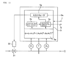
- Figure 14 is a block diagram of an improved pressure flow controller for which the aforementioned empirical flow rate equation Qc'. This was previously disclosed by inventors of the present invention in the TOKU-GAN No.2001-399433.
- the controller in the said Figure 14 is constituted as a flow controller. However, it is easily understood that it can be turned to be a differential pressure type flowmeter by eliminating a control valve 21, a valve driving part 23, and a flow rate comparison part 23e.
- 20 designates an orifice, 21 a control valve, 22 a valve driving part, 23 a control circuit, 23a a pressure ratio computation part, 23b a pressure ratio computation part, 23c a flow rate computation part, 23d a flow rate computation part, 23e a flow rate comparison part, P 1 a fluid pressure detector on the upstream side of an orifice, P 2 a fluid pressure detector on the downstream side of an orifice, T a fluid temperature detector, Qs a flow rate setting value signal, ⁇ Q a flow rate difference signal, and Qc' a flow rate computation value.
- rc criticality rc is given by an equation (2/(n+1)) n/(n-1) , (where n is the specific heat ratio of a gas).
- n is the specific heat ratio of a gas.
- a flow rate difference ⁇ Q between a set flow rate Qs and a computed flow rate Qc is computed with a flow rate comparison part 23e to operate a valve driving part 22 to control valve 21 so that the flow rate difference ⁇ Q reaches zero.
- a flow rate comparison part 23e, a control valve 21 and a valve driving part 22 can be eliminated.
- Curve A in Figure 15 shows flow rate measurements or flow rate control characteristics with an improved pressure type flowmeter and the like
- Patent Literature 1 TOKU-KOU-SHO No.59-19365 Public Bulletin
- Patent Literature 2 TOKU-KOU-SHO No.59-19366 Public Bulletin
- Patent Literature 3 TOKU-KAI-HEI No.10-55218 Public Bulletin
- a measurement error (%SP or %FS) becomes comparatively larger to the reference set flow rate when a pressure P 2 on the downstream side of an orifice becomes vacuum of less than approximately 200Torr, thus resulting in occurrence of difficulties in practical use.
- the present invention as claimed in Claim 4 is fundamentally so constituted that flow rate measurements can be performed with high accuracy over the wide flow rate range by combining a differential pressure type flowmeter for measuring a flow rate range of 100%-10% of the maximum flow rate range and a differential pressure type flowmeter for measuring a flow rate range of 10%-1% of the maximum flow rate range and by switching a fluid to be measured in accordance with the aforementioned flow rate ranges using a switching valve, to supply the fluid to the aforementioned differential pressure type flowmeters.
- the present invention as claimed in Claim 7 is fundamentally so constituted by forming it with a valve body 12 provided with a fluid inlet a, a fluid outlet b, a mounting hole 17a for the No.1 switching valve 10, a mounting hole 17b for the No.2 switching valve 11, a mounting hole 18a for a fluid pressure detector 2 on the upstream side of an orifice, a mounting hole 18b for a fluid pressure detector 3 on the downstream side of an orifice, a mounting hole for a fluid temperature detector 4 on the upstream side of an orifice, fluid passages 16a, 16b and 16e for directly passing through a fluid inlet a, the undersides of a mounting hole 17a for the No.1 switching valve 10, a mounting hole 18a for a fluid pressure detector 2 on the upstream side of an orifice and a mounting hole 17b for the No.2 switching valve 11 which are made in the interior of the aforementioned valve body 12, a fluid passage 16f for communication of the underside of a mounting hole 17a for the
- the present invention as claimed in Claim 8 according to Claim 7 is so made that a flow rate range up to 100%-10% of the maximum flow rate is measured by closing the No.1 switching valve 10 and opening the No.2 switching valve 11, while a flow rate range up to10%-1% of the maximum flow rate is measured by opening the No.1 switching valve 10 and closing the No.2 switching valve 11.
- the present invention as claimed in Claim 9 according to Claim 4 or Claim 7 is so constituted that either one of the No.1 switching valve 10 or No.2 switching valve 11 is made to be a normal/close type valve and the other a normal/open type valve, and a operating fluid is supplied from one control electromagnetic valve Mv to driving cylinders 10a and 10b of both switching valves.
- a pressure detector 2 to detect a pressure on the upstream side of an orifice a pressure detector 3 to detect a pressure on the down stream side of an orifice, and a temperature detector 4 to detect a temperature on the upstream side of an orifice are made sharable with both differential pressure type flowmeters.
- the structure of a differential pressure type flowmeter and the like is remarkably simplified, and it is so constituted that a flow rate computation is performed by using a novel empirical flow rate computation equation which makes it possible to obtain a computation flow rate value corresponding with the measured value with high accuracy, thus allowing the flowmeter and the like to be manufactured at low cost, and moreover, they take an inline form, and can be used without constraints of fitting positions, and a control flow rate is not influenced nearly at all by pressure changes, enabling highly accurate flow rate measurements or flow rate control in real time.
- a control computation circuit is equipped with a correction data memory circuit for pressure changes, and a correction circuit for a computation flow rate, thus enabling easy correction even when pressure changes arise on the secondary side of an orifice. Therefore, highly accurate flow rate measurements or flow rate control can be achieved virtually without being influenced by pressure changes even a pressure P 2 on the secondary side of an orifice is under a vacuum (a low pressure of less than 50Torr).
- a differential pressure type flowmeter for a small flow quantity and a differential pressure type flowmeter for a large flow quantity are organically and integrally assembled. Therefore, highly accurate flow rate measurements with errors (%SP) of less than 1 (% SP) can be performed continuously over a wide flow rate range from the rated flow rate (100%) to a small flow quantity (1%) or approximately 1 % of the rated flow rate, by both differential pressure type flowmeters being switched.
- control system can be further simplified by making the switching operation, for both differential pressure type flowmeter for a small quantity and differential pressure type flowmeter for a large quantity, automatic with a single-system control signal Sc.
- the present invention achieves excellent, practical effects that all types of gases are measured or controlled over the wide flow rate range with high accuracy even when a gas of less than 100Torr is used although the differential pressure type flowmeter and the like are structured simply and at low cost.
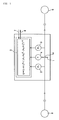
- Figure 1 is a basic block diagram of a differential pressure flowmeter according to the first embodiment of the present invention.
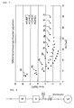
- Figure 2 is a diagram to show error characteristics of a differential pressure type flowmeter in Figure 1.
- Figure 3 is a diagram to show the relationships of "a flow rate, the secondary side pressure and error" in the event that the pipe resistance on the secondary side is changed at the time when a pressure P 2 on the downstream side of an orifice is the vacuum.
- Figure 4 shows a measurement circuit utilized to obtain data in Figure 3.
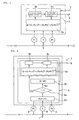
- Figure 5 is a basic block diagram of a differential pressure flowmeter according to the second embodiment of the present invention.
- Figure 6 is a basic block diagram of a differential pressure flowmeter according to the third embodiment of the present invention.
- Figure 7 is a system diagram to show the whole configuration of a differential pressure type flowmeter according to the fourth embodiment of the present invention.
- Figure 8 is a cross-sectional schematic diagram of a major part of a differential pressure type flowmeter according to the fourth embodiment of the present invention.
- Figure 9 is an explanatory drawing of a switching operation system of a differential pressure type flowmeter for which a normal open type switching valve and a normal close type switching valve are employed according to the present invention.
- Figure 10 is a basic block diagram of the first embodiment of a differential pressure type flow controller according to the present invention.
- Figure 11 is a basic block diagram of the second embodiment of a differential pressure type flow controller according to the present invention.
- Figure 12 is a basic block diagram of the third embodiment of a differential pressure type flow controller according to the present invention.
- Figure 13 is a basic block diagram of the fourth embodiment of a differential pressure type flow controller according to the present invention.
- Figure 14 is a block diagram of an improved pressure type flow controller disclosed previously.
- Figure 15 is a diagram to show flow characteristics of an improved pressure type flow controller disclosed previously.
- FIG. 1 is a basic block diagram of a differential pressure type flowmeter according to the first embodiment of the present invention.
- the said differential pressure type flowmeter comprises an orifice 1, an absolute pressure type pressure detector on the upstream side of an orifice 2, an absolute pressure type pressure detector on the downstream side of an orifice 3, a gas absolute temperature detector on the upstream side of an orifice 4, a control computation circuit 5, an output terminal 6, an input terminal 7, and the like.
- 8 designates a gas supply facility and 9 a gas use facility (a chamber).
- a gas flow rate Q passing through an orifice 1 under differential pressure conditions is computed by an empirical flow rate equation as the below-stated equation (1), and the computed value is outputted to the outside through the output terminal 6.
- Q C 1 ⁇ P / T ⁇ ( ( P 2 / P 1 ) m ⁇ ( P 2 / P 1 ) n ) 1 / 2
- ⁇ designates a gas density, K a specific ratio of a gas, P 1 a pressure on the upstream side of an orifice, P 2 a pressure on the downstream side of an orifice, T a gas temperature, R a gas constant, and S a cross-sectional area of an orifice.
- K a specific ratio of a gas
- P 1 a pressure on the upstream side of an orifice
- P 2 a pressure on the downstream side of an orifice
- T a gas temperature
- R a gas constant
- S cross-sectional area of an orifice
- Q designates a volume flow rate (SCCM) converted to a standard state
- C a coefficient including a cross-sectional area S of an orifice 1
- P 1 an absolute pressure (Pa) on the upstream side of an orifice
- P 2 an absolute pressure (Pa) on the downstream side of an orifice
- T an absolute temperature (K) on the upstream side of an orifice.
- Figure 2 is the measured values to show relationships of a set flow rate value (%), pressures P1 and P2 (Torr) and error (%SP) of a differential pressure type flowmeter (100% set value 2000sccm) in Figure 1.
- Figure 3 is a diagram to show relationships of a pressure P 2 (Torr) on the secondary side of an orifice, a set flow rate (%), errors (%SP) and piping conditions on the secondary side of a differential pressure type flowmeter according to the present invention, where 9a is in the event that a set flow rate (%) is 100sccm, 9b 200sccm, 9c 400sccm, 9d 600sccm, 9g 1200sccm, 9j 1800scm, and 9k 2000sccm (100%) respectively.
- the maximum flow rate (100%) of a differential pressure type flowmeter employed herewith is 2000sccm.
- Figure 4 illustrates a measurement circuit to obtain error correction coefficients in Figure 3, for which a pressure type flow controller is employed for a standard flow controller SF, and a control valve V 2 is removably secured to change piping conditions on the secondary side, to adjust the flow rates of a supply gas (N 2 to be adjusted at 11 points) at an interval of 200sccm over the flow rate range of 100sccm-2000sccm by using the said standard flow controller SF, to measure P 1 , P 2 and Q of a differential pressure type flowmeter A, and also to measure a pressure P 2 on the downstream side of an orifice each time adjustment is made.
- a supply gas N 2 to be adjusted at 11 points
- Adjustments of the secondary side pipe resistance were made on 4 cases, that is, when no control valve V 2 is used (or when a differential pressure type flowmeter A is directly connected to a vacuum pump with an approximately 100mm long pipe of an internal diameter of 4.35mm ⁇ ), when a control valve V 2 with the Cv value of 0.3 is used, when a control valve V 2 with the Cv value of 0.2 is used, and when a control valve V 2 with the Cv value of 0.1 is used.
- a supply pressure P 1 to a pressure type flow controller was approximately 300kPaG, and the secondary side of an orifice of a differential pressure type flowmeter A was continuously evacuated by a vacuum pump Vp (300 liters/min and the maximum pressure achieved 1.2 ⁇ 10 -2 Torr).
- correction data in the afore-shown Table1 are utilized to correct actually measured values of the differential pressure type flowmeter in the event that a pressure P 2 on the secondary side of an orifice changed for any circumstances.
- a differential pressure type flowmeter in use with 2000sccm displays 2000sccm for the measured value, and a pressure P 2 on the downstream side of an orifice is 60 Torr, it means that the measured value (2000sccm) includes an error (%SP) of +2%. Then, the measured value of 2000sccm is corrected to 1960sccm by correcting for +2%.
- FIG 5 illustrates a basic constitution of the present invention for which the aforementioned correction means is employed. That is, a control computation circuits 5 of a differential pressure type flowmeter in Figure 1 showing the first embodiment is equipped with a correction data memory circuit 5b and a flow rate value correction computation circuit 5c.
- a pressure P 2 on the downstream side of an orifice is referred to a flow rate value Q computed by using a flow rate empirical equation with the aforementioned flow rate computation circuit 5a, to draw out the error (%SP) with a pressure P 2 from the correction data memory circuit 5b, thus eliminating much of the said error (%SP) from the aforementioned flow rate computation value Q and outputting, to an output terminal 6 to the outside, a flow rate value Q' close to vicinity of the value after correcting with the correction computation circuit 5c.
- Figure 6 illustrates the third embodiment of the present invention.
- a pressure ratio computation circuit 5d a critical conditions judgment circuit 5e, and a flow rate computation circuit 5f for critical conditions are added to a control computation circuit 5 in Figure 5.
- the ratio (y) of a pressure P 1 on the upstream side of an orifice versus a pressure P 2 on the downstream side of an orifice is determined, and a pressure ratio (y) and a critical pressure ratio (yc) are compared.
- a corrected flow rate value Q' is outputted from the output terminal 6.
- the flow rate range of 100-10(%) is the limit to make possible restraining errors of flow rate measurement values to the range (for example, less than 1 (%SP)) bearable for practical use.
- the flow rate is less than 10 (%), it becomes difficult to hold errors to less than 1 (%SP) even with a correction being performed.
- Figure 7 is a whole block diagram of a differential pressure type flowmeter according to the fourth embodiment.
- 10 designates the No.1 switching valve (NC type), 11 the No.2 switching valve (NC type), a a gas inlet side, b a gas outlet side, 1' the No.1 orifice (for a small quantity), 1" the No.2 orifice (for a large quantity), 5' the No.1 control computation circuit, and 5" the No.2 control computation circuit.
- a differential pressure type flow controller for a small flow quantity side i.e., a flow rate range of 10-100sccm
- a differential pressure type flow controller for a large flow quantity side i.e., a flow rate range of 100-1000sccm
- highly accurate measurements of a flow rate can be achieved over the wide flow rate range of 1000sccm (100%) - 10sccm (1%) with errors of less than 1 (%SP) by using both differential pressure type flow controllers.
- Figure 8 is a cross-sectional schematic diagram of a major part of a differential pressure type flowmeter according to the fourth embodiment of the present invention. It is to be noted that the No.1 and No.2 control computation circuits 5' and 5" and the like are omitted herewith.
- 12 designates a body, 13a and 13b seals, 14a a mounting bolt for an absolute type pressure detector 2 on the upstream side of an orifice, 14b a mounting bolt for an absolute type pressure detector 3 on the downstream side of an orifice, 15a and 15b diaphragm mechanisms, and 11a and 11b driving cylinders.
- a body 12 made of stainless steel is formed by hermetically assembling a gas inlet element 12a, a gas outlet element 12b, the No.1 body element 12c and the No.2 body element 12d.
- a mounting hole for a gas temperature detector 4 on the upstream side of an orifice is formed on the No.1 body element 12c.
- fluid passages 16a, 16b and 16e for communication of a fluid inlet a, a fluid outlet b, the underside of a mounting hole 17a for the No.1 switching valve 10, the underside of a mounting hole 18b for a pressure detector 2 on the upstream side of an orifice and the underside of a mounting hole 17b for the No.2 switching valve 11; a fluid passage 16f for communication of the undersides of a mounting hole 17a and a mounting hole 17b; a fluid passage 16c for communication of the undersides of a mounting hole 17b and a mounting hole 18b; and a fluid passage 16d for communication of the underside of a mounting hole 18b and a fluid outlet b.
- valve seats for communication of fluid passages 16e and 16d formed on the undersides of the aforementioned mounting holes 17a and 17b are made to open/close with valve mechanisms 15a and 15b for the No.1 switching valve 10 and No.2 switching valve 11.
- opening and closing valve seats opening and closing are performed between the passage 16e and passage 16f and also between the passage 16c and passage 16b.
- a passage 16c communicates between a mounting hole 17b and a mounting hole 18b all the time.
- the No.1 switching valve 10 is made to close, while the No.2 switching valve 11 is made to open so that a gas flowed in from a gas inlet a is flowed out from a gas outlet through a passage 16a, an orifice 1", a passage 16b, a passage 16c and a passage 16d.
- a flow rate computation is performed with the No.2 control computation circuit 5" (not illustrated) to be outputted to appropriate points.
- the No.1 switching valve 10 is made open while the No.2 switching valve 11 is made close so that a gas flows out from a gas outlet b through a passage16a, a passage 16e, an orifice 1' for a small flow quantity, a passage 16f, a passage 16c and a passage 16d.
- a flow rate computation is performed with the No.1 control computation circuit 5', to be outputted to appropriate points just same as in the case of measurements for a large flow quantity range.
- the No.1 switching valve 10 and No.2 switching valve 11 are made to be valves of a normal close type, and it is so made that an operating fluid is supplied to driving cylinders 11a and 11b of switching valves 10 and 11 respectively via independent control electromagnetic valves.
- either one of the No.1 switching valve 10 and No.2 switching valve can be made to be a valve of a normal close type while the other is made to be a valve of a normal open type so that an operating fluid is supplied to both switching valves 10 and 11 from one control electromagnetic valve.
- switching operation for both switching valves 10 and 11 can be performed with one control electromagnetic valve Mv, and a control signal Sc can be made of one channel.
- FIG 10 illustrates the first embodiment of a differential pressure type flow controller according to the present invention.
- the aforementioned differential pressure type flowmeter shown in Figure 1 is equipped with a control valve 21 and a valve driving part 22, and a control computation circuit 5 is equipped with a flow rate comparison circuit 5g whereat a flow rate difference ⁇ Q between a set flow rate Qs inputted from the outside and the computed flow rate Q computed with a flow rate computation circuit 5a is computed, thus the said flow rate difference ⁇ Q being inputted to a valve driving part 22 as a control signal.
- a control valve 21 is operated so that the aforementioned flow rate difference ⁇ Q is moved toward a zero direction, thus the gas flow rate passing through an orifice 1 being controlled to be a set flow rate Qs.
- FIG 11 illustrates the second embodiment of a differential pressure type flow controller.
- the aforementioned differential pressure type flow controller in Figure 5 is equipped with a control valve 21 and a valve driving part 22, and a control computation circuit 5 is equipped with a flow rate comparison circuit 5g.
- a flow rate difference ⁇ Q is computed by using the corrected flow rate Q' which has been error-corrected on the computed flow rate Q with the correction computation circuit, thus a control valve 21 being controlled by opening/closing toward to the direction where the said flow rate difference ⁇ Q becomes zero.
- Figure 12 illustrates the third embodiment of a differential pressure type flow controller. It is so constituted that the afore-mention differential pressure type flowmeter is equipped with a control valve 21 and a valve driving part 22, and a control computation circuit 5 is equipped with a flow rate comparison circuit 5g while a correction data memory circuit 5b and a correction computation circuit 5c are removed.
- a flow rate difference ⁇ Q is computed by using the computed flow rate Q from the No.2 flow rate computation circuit 5f when the gas flow is under critical conditions
- a flow rate difference ⁇ Q is computed by using the computed flow rate Q from the No.1 flow rate computation circuit 5a when the gas flow is non-critical conditions so that a control valve 21 is controlled by opening/closing toward the direction where the said flow rate difference ⁇ Q becomes zero.
- Figure 13 illustrates the fourth embodiment of a differential pressure type flow controller. It is so constituted that the aforementioned differential pressure type flowmeter in Figure 6 is equipped with a control valve 21 and a valve driving part 22, and a control computation circuit 5 is equipped with a flow rate comparison circuit 5g.
- a flow rate difference ⁇ Q is computed by using the computed flow rate Q from the No.2 flow rate computation circuit 5f when the gas flow is under critical conditions, and a flow rate difference ⁇ Q is computed by using the flow rate Q' from the correction computation circuit 5c corrected to the computed flow rate Q from the flow rate computation circuit 5a so that a control valve 21 is controlled by opening/closing toward the direction where the said flow rate difference ⁇ Q becomes zero.
- the present invention is widely usable mainly for semiconductor manufacturing facilities, at chemical plants, food-product processing plants and the like. It is also widely usable in the fields where fluids such as gases, liquids and the like are dealt with.
Landscapes
- Physics & Mathematics (AREA)
- General Physics & Mathematics (AREA)
- Fluid Mechanics (AREA)
- Engineering & Computer Science (AREA)
- Automation & Control Theory (AREA)
- Measuring Volume Flow (AREA)
- Flow Control (AREA)
Abstract
A cost reduction can be achieved by making a differential pressure type flowmeter simple in structure, and highly accurate flow rate measurements can be attained over the wide flow rate range of 100%-1 % with errors E of less than 1 (%SP) both in real time and in a state of inline.
To achieve the ends, a differential pressure type flowmeter comprises an orifice, a detector to detect a fluid pressure P1 on the upstream side of an orifice, a detector to detect a fluid pressure P2 on the downstream side of an orifice, a detector to detect a fluid temperature T on the upstream side of an orifice, and a control computation circuit to compute a fluid's flow rate Q passing through an orifice by using the pressure P1, pressure P2 and temperature T detected with the aforementioned detectors, and the aforementioned fluid's flow rate Q is computed with the equation Q=C1 · P1/√T· ((P2/P1)m - (P2/P1)n)½ (where C1 is a proportional constant, and m and n are constants).
To achieve the ends, a differential pressure type flowmeter comprises an orifice, a detector to detect a fluid pressure P1 on the upstream side of an orifice, a detector to detect a fluid pressure P2 on the downstream side of an orifice, a detector to detect a fluid temperature T on the upstream side of an orifice, and a control computation circuit to compute a fluid's flow rate Q passing through an orifice by using the pressure P1, pressure P2 and temperature T detected with the aforementioned detectors, and the aforementioned fluid's flow rate Q is computed with the equation Q=C1 · P1/√T· ((P2/P1)m - (P2/P1)n)½ (where C1 is a proportional constant, and m and n are constants).
Description
- The present invention is concerned with improvements in or relating to a differential pressure type flowmeter and differential pressure type flow controller (together hereinafter called a differential pressure type flowmeter and the like) employed for semiconductor manufacturing facilities, at chemical plants, food-products processing plants and the like. The invention may be manufactured at a low cost and with a structural simplicity, and used in a state of so-called inline, and at the same time, make it possible that a flow rate of a fluid either under of criticality or non-criticality is measured or controlled with accuracy and in real time even in a small flow quantity range under a vacuum.
- Heretofore, for semiconductor manufacturing facilities and at chemical plants, a differential pressure flowmeter and the like such as a mass flow type flowmeter (a thermal type mass flow meter) and the like and a buildup type flowmeter and the like have been widely used to measure or control a flow rate of process gases, raw material gases and the like.
- However, with a thermal type mass flowmeter and the like, there have been seen a number of difficulties such as a low responsivity, a poor measuring accuracy in a small flow quantity range, a large number of operational problems, a limited variety of gases subject to control, and being easily influenced by pressure changes and the like.
- Similarly, with a buildup type flowmeter and the like, there have been seen some difficulties such as being difficult in measuring or controlling a flow rate in real time, not being able to use in a state of inline, an existence of restraints of a pressure of gases subject to control, a separate line required for measurements and the like.
- On the other hand, a differential pressure type flowmeter and the like for which an orifice and a manometer are employed demonstrates excellent effects such as having nearly no restraints of the type of gases subject to control, being usable in a state of inline, and also measuring and controlling a flow rate being able to be performed in real time.
- However, this type of a differential pressure type flowmeter and the like uses an equation for a flow rate computation derived from Bernoulli's theorem with the assumption that the fluid is non-compressible, and then the flow rate of the fluid is computed by giving some corrections to it. Therefore, if large pressure changes of the fluid arise (that is, when approximations that the fluid is non-compressibile break), a substantial drop in accuracy of measuring and controlling a flow rate cannot be avoided, thus resulting in a failure of accurate flow rate measurements and controls.
- To solve these difficulties with the aforementioned differential pressure type flowmeter and the like, a pressure type flowmeter and the like has been developed and disclosed (TOKU-KAI-HEI No. 10-55218 and others) wherewith critical conditions of a fluid passing through an orifice, that is, a pressure P1 on the upstream side of an orifice and a pressure P2 on the downstream side of an orifice being forcibly set to make the velocity of a fluid to be the velocity of sound, and the flow rate of a liquid Q is computed by the theoretical equation Q=KP1 under the critical conditions.
- However, even with the said pressure type flowmeter and the like, non-critical conditions occur when a fluid is in a small flow quantity range (that is, when a pressure P1 on the upstream side of an orifice and a pressure P2 on the downstream side to an orifice are in a state of being close), thus resulting in large errors in a flow rate measurement value Q or a flow rate control value Q.
- Namely, with a conventional differential pressure flowmeter (or a pressure type flowmeter) and the like, it is so made that an equation for a flow rate computation derived from Bernoulli's theorem with the assumption that a fluid is non-compressibile is used, and under non-critical conditions before a fluid reaches the velocity of sound (a non-sound velocity range), a flow rate on the downstream side is determined by the equation Qc=SC(P2(P1 - P2))1/2 /T1/2, while under critical conditions after having reached the velocity of sound (a sound velocity range), a flow rate Q is computed by an equation Qc=SCP1/T1/2 (where T is an absolute temperature of a fluid passing through an orifice, S is a cross-sectional area of an orifice and C is a proportional factor).
- Critical conditions for the velocity of a fluid to reach the velocity of sound is given by a critical value rc of a pressure ratio P2/P1. The critical value rc is determined by the equation P2/P1=rc=(2/(n+1))n/(n-1) using a specific heat ratio n of a gas.
- Furthermore, a specific heat ratio n is given by the equation n=Cp/Cv where Cp is a constant pressure specific heat and Cv is a constant volume specific heat. With biatom-molecular gases, n is n=7/5=1.4, and rc is Rc=0.53, while with non-linear type triatom-molecular gases, n is n=8/6=1.33, and rc is Rc=0.54.
- To solve problems with the aforementioned conventional differential pressure type flowmeter (or a pressure type flowmeter), a flow rate value computed with the previous theoretical flow rate equation derived from the assumption that a fluid to be used under non-critical conditions is non-compressibile is compared with the actually measured flow rate value, to derive an empirical flow rate equation having a plurality of parameters Qc'= SC/T1/2 · P2m (P1- P2)n =KP2 m(P1 - P2)n from a previous theoretical flow rate equation Qc= SC/T1/2 (P2(P1 - P2))1/2 , and to determine the aforementioned parameters m and n to make a flow rate value computed by the empirical flow rate equation Qc' equal to a measured value, thus an empirical flow rate equation Qc' that suitably matches with the fluid of compressibility being introduced by inventors of the present invention, and disclosed in TOKU-GAN No.2001-399433.
- With the aforementioned empirical flow rate equation Qc', a proportional constant K is given by SC/T1/2 and computed from conditions of substance and absolute temperature T. P1 designates a pressure on the upstream side of an orifice and P2 a pressure on the downstream side of an orifice. kPaA (kilo Pascal Absolute pressure) is the unit. Further, in the measured flow rate range of 10-30sccm (a unit of a flow rate in a normal state), it has been found that parameters m and n are m=0.47152 and n=0.59492 respectively.
- The values of the aforementioned 2 parameters m and n have a dependence on the range of a flow rate to be measured and the type of a gas. The aforementioned values m=0.4715 and n=0.59492 are values that hold true when the flow rate is in the range of 10-30sccm. So, m and n don't hold true when the range of a flow rate is 10-100sccm or 100-1000sccm, and accordingly they deviate from these values.
- Figure 14 is a block diagram of an improved pressure flow controller for which the aforementioned empirical flow rate equation Qc'. This was previously disclosed by inventors of the present invention in the TOKU-GAN No.2001-399433. The controller in the said Figure 14 is constituted as a flow controller. However, it is easily understood that it can be turned to be a differential pressure type flowmeter by eliminating a
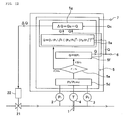
control valve 21, avalve driving part 23, and a flowrate comparison part 23e. - Referring to Figure 14, 20 designates an orifice, 21 a control valve, 22 a valve driving part, 23 a control circuit, 23a a pressure ratio computation part, 23b a pressure ratio computation part, 23c a flow rate computation part, 23d a flow rate computation part, 23e a flow rate comparison part, P1 a fluid pressure detector on the upstream side of an orifice, P2 a fluid pressure detector on the downstream side of an orifice, T a fluid temperature detector, Qs a flow rate setting value signal, △Q a flow rate difference signal, and Qc' a flow rate computation value.
- With the said controller, firstly a pressure ratio P2/P1 is computed with the detected upstream side pressure P1 and downstream side pressure P2 (23a), a judgment is made continually to find if the fluid is under critical conditions or non-critical conditions (23b), and the flow rate is computed with a flow rate equation Qc=KP when under critical conditions (23c), while the flow rate is computed with an empirical flow rate equation Qc'=KP2 m(P1 - P2)n when under non-critical conditions.
- As stated above, the value of criticality rc is given by an equation (2/(n+1))n/(n-1), (where n is the specific heat ratio of a gas). With bi-atom molecular gases, rc is rc=0.53 and with non-linear tri-atom molecular gases, rc is rc=0.54. Therefore, rc is written as rc=approx. 0.5.
- A flow rate difference ΔQ between a set flow rate Qs and a computed flow rate Qc is computed with a flow
rate comparison part 23e to operate avalve driving part 22 to controlvalve 21 so that the flow rate difference ΔQ reaches zero. However, when it is used as a flow meter, as stated above, a flowrate comparison part 23e, acontrol valve 21 and avalve driving part 22 can be eliminated. - Curve A in Figure 15 shows flow rate measurements or flow rate control characteristics with an improved pressure type flowmeter and the like, while Curve B shows flow rate measurements or flow rate control characteristics with an conventional pressure type flowmeter and the like when an equation Qc=KP1 is used under non-critical conditions. As apparent from Figure 15, with the improved pressure type flowmeter and the like, a flow rate equation Qc=KP1 is used when under critical conditions, while an empirical flow rate equation Qc'=KP2m (P1 - P2)n is used when under non-critical conditions, thus an accurate flow rate Q in proportion to the set flow rate being able to be computed, linearity to a set % of a flow rate being held as shown by Curve A in Figure 15, and the comparatively accurate flow rate measurement and control being ensured even in the range of a small flow quantity.
- Patent Literature 1: TOKU-KOU-SHO No.59-19365 Public Bulletin
- Patent Literature 2: TOKU-KOU-SHO No.59-19366 Public Bulletin
- Patent Literature 3: TOKU-KAI-HEI No.10-55218 Public Bulletin
- With the aforementioned improved pressure type flowmeter and the like shown in Figure 14, flow rate measurements or control can be achieved with comparatively high accuracy if the flow rate is in a small flow quantity range up to approximately 10% of the maximum flow rate as shown by Curve A in Figure 15, thus excellent practical effects being attained.
- However, when a flow rate is in a small flow quantity range of less than approximately 10% of the maximum flow rate, problems that a practical flow rate measurements or flow rate control cannot be achieved with accuracy arise in reality.
- Furthermore, with the said improved pressure type flowmeter and the like, a measurement error (%SP or %FS) becomes comparatively larger to the reference set flow rate when a pressure P2 on the downstream side of an orifice becomes vacuum of less than approximately 200Torr, thus resulting in occurrence of difficulties in practical use.
- It is an object of the present invention to provide a differential pressure type flowmeter and the like at a low cost and simple in structure to solve the problems with an improved pressure type flowmeter and the like previously developed by inventors of the present invention, thus making it possible to achieve highly accurate flow rate measurements or control over a wide flow rate range from the maximum flow rate (100%) to approximately 1 % of the maximum flow rate, and even when a pressure P2 on the downstream side of an orifice is in the vacuum and makes changes, by storing the error data obtained by actual measurements beforehand in the memory device, and then by correcting flow rate computation values in reference with the correction data.
- The present invention as claimed in
Claim 1 is fundamentally so constituted, with a differential pressure type flowmeter comprising an orifice, a detector to detect a fluid pressure P1 on the upstream side of an orifice, a detector to detect a fluid pressure P2 on the downstream side of an orifice, a detector to detect a fluid temperature T on the upstream side of an orifice, and a control computation circuit to compute a fluid's flow rate passing through an orifice with the pressure P1, pressure P2 and temperature T detected by the aforementioned detectors, the aforementioned fluid's flow rate Q is computed with an equation Q=C1· P1/√T· ((P2/P1)m - (P2/P1)n)½ (where C1 is a proportional constant, and m and n are constants). - The present invention as claimed in
Claim 2 is fundamentally so constituted, with a differential pressure type flowmeter comprising an orifice, a detector to detect a fluid pressure P1 on the upstream side of an orifice, a detector to detect a fluid pressure P2 on the downstream side of an orifice, a detector to detect a fluid temperature T on the upstream side of an orifice, and a control computation circuit to compute a fluid's flow rate Q passing through an orifice with the pressure P1 and pressure P2 and temperature T detected by the aforementioned detectors, the aforementioned control computation circuit is installed with a flow rate computation circuit wherewith a fluid's flow rate Q is computed with an equation Q=C1· P1/√T · ((P2/P1)m - (P2/P1) n)1/2 (where C1 is a proportional constant, and m and n are constants), a correction data memory circuit wherein changes in the pressure P2 on the downstream side of an orifice obtained by actual measurements beforehand and flow rate errors of the aforementioned fluid's flow rate Q are storable, and a flow rate correction computation circuit to correct the aforementioned computed fluid's flow rate Q with the correction data from the correction data memory circuit, thus the computed fluid's flow rate Q being corrected depending on changes of a pressure P2 on the downstream side of an orifice, to output a corrected flow rate value Q'. - The present invention as claimed in
Claim 3 according toClaim 2 is so constituted that, by installing, with a control computation circuit, a pressure ratio computation circuit to compute the ratio of a fluid pressure P1 on the upstream side of an orifice and a fluid pressure P2 on the downstream side of an orifice, a critical condition judgment circuit to judge a state of the fluid by comparing the aforementioned computed pressure ratio and a fluid's critical pressure ratio, and a No.2 flow rate computation circuit to compute the fluid's flow rate Q by using the equation Q=KP1 (where K is a proportional constant) when the fluid is under critical conditions, thus outputting a fluid's flow rate Q computed with the aforementioned No.2 flow rate computation circuit when the fluid is under critical conditions, and also outputting a fluid's flow rate value Q' corrected with the flow rate correction computation circuit when the fluid is under non-critical conditions. - The present invention as claimed in
Claim 4 is fundamentally so constituted that flow rate measurements can be performed with high accuracy over the wide flow rate range by combining a differential pressure type flowmeter for measuring a flow rate range of 100%-10% of the maximum flow rate range and a differential pressure type flowmeter for measuring a flow rate range of 10%-1% of the maximum flow rate range and by switching a fluid to be measured in accordance with the aforementioned flow rate ranges using a switching valve, to supply the fluid to the aforementioned differential pressure type flowmeters. - The present invention as claimed in
Claim 5 according toClaim 4 is so made that both differential pressure type flowmeters are made to be differential pressure type flowmeters comprising an orifice, a detector to detect a fluid pressure P1 on the upstream side of an orifice, a detector to detect a fluid pressure P2 on the downstream side of an orifice, a detector to detect a fluid temperature T on the upstream side of an orifice, and a control computation circuit to compute a fluid's flow rate by using the pressure P1, pressure P2, and temperature T detected by the aforementioned detectors, and the aforementioned fluid's flow rate Q is computed with the equation Q=C1• P1/√T· ((P2/P1)m - (P2/P1)n)½ (where C1 is a proportional constant, and m and n are constants). - The present invention as claimed in
Claim 6 according toClaim 4 is so constituted that both differential pressure type flowmeters are made to be differential pressure type flowmeters comprising an orifice, a detector to detect a fluid pressure P1 on the upstream side of an orifice, a detector to detect a fluid pressure P2 on the downstream side of an orifice, a detector to detect a fluid temperature T on the upstream side of an orifice, and a control computation circuit to compute a fluid's flow rate by using the pressure P1, pressure P2, and temperature T detected by the aforementioned detectors; and the aforementioned control computation circuit is equipped with a flow rate computation circuit wherewith a fluid's flow rate Q is computed with the equation Q=C1· P1/√T· ((P2/P1)m - (P2/P1) n)1/2 (where C1 is a proportional constant, and m and n are constants), a correction data memory circuit wherein changes of a pressure P2 on the downstream side of an orifice obtained by actual measurements beforehand and flow rate errors of the aforementioned fluid's flow rate Q is stored, and a flow rate correction computation circuit to correct the aforementioned computed fluid's flow rate Q with the correction data from the correction data memory circuit, thus computed fluid's flow rate Q being corrected depending on changes of a pressure P2 on the downstream side of an orifice to output a corrected flow rate value Q'. - The present invention as claimed in
Claim 7 is fundamentally so constituted by forming it with a valve body 12 provided with a fluid inlet a, a fluid outlet b, amounting hole 17a for the No.1switching valve 10, amounting hole 17b for the No.2switching valve 11, amounting hole 18a for afluid pressure detector 2 on the upstream side of an orifice, amounting hole 18b for afluid pressure detector 3 on the downstream side of an orifice, a mounting hole for afluid temperature detector 4 on the upstream side of an orifice,fluid passages mounting hole 17a for the No.1switching valve 10, amounting hole 18a for afluid pressure detector 2 on the upstream side of an orifice and amounting hole 17b for the No.2switching valve 11 which are made in the interior of the aforementioned valve body 12, afluid passage 16f for communication of the underside of amounting hole 17a for the No.1switching valve 10 and the underside of amounting hole 17b for the No.2switching valve 11, afluid passage 16c for communication of the underside of amounting hole 17b for the No.2switching valve 11 and the underside of amounting hole 18b for thefluid pressure detector 3 on the downstream side of an orifice, afluid passage 16d for communication of the underside of amounting hole 18b for thefluid pressure detector 3 on the downstream side of an orifice and a fluid outlet b, afluid pressure detector 2 on the upstream side of an orifice and afluid pressure detector 3 fixed to theaforementioned mounting holes fluid temperature detector 4 on the upstream side of an orifice, the No.1switching valve 10 wherewith opening and closing are conducted between theaforementioned fluid passage 16e andfluid passage 16f, the No.2switching valve 11 wherewith opening and closing are conducted between theaforementioned fluid passage 16b andfluid passage 16c, an orifice 1' for a small flow quantity installed halfway to theaforementioned fluid passage 16f, anorifice 1" for a large flow quantity installed on the aforementioned fluid passage16a orfluid passage 16b, and a control computation circuit to compute a fluid's flow rate Q passing through an orifice 1' for a small flow quantity and anorifice 1" for a large flow quantity depending on the pressure P1, pressure P2 and temperature T detected by theaforementioned pressure detectors temperature detector 4 respectively by using the equation Q=C1· P1√T· ((P2/P1)m-(P2/P1)n)½ ,thus making it possible to measure a flow rate in a large flow quantity range by closing the aforementioned No.1switching valve 10 and opening the No.2switching valve 1, while a flow rate in a small quantity range is measured by opening the aforementioned No.1switching valve 10 and closing the No.2switching valve 11. - The present invention as claimed in
Claim 8 according toClaim 7 is so made that a flow rate range up to 100%-10% of the maximum flow rate is measured by closing the No.1switching valve 10 and opening the No.2switching valve 11, while a flow rate range up to10%-1% of the maximum flow rate is measured by opening the No.1switching valve 10 and closing the No.2switching valve 11. - The present invention as claimed in
Claim 9 according toClaim 4 orClaim 7 is so constituted that either one of the No.1switching valve 10 or No.2switching valve 11 is made to be a normal/close type valve and the other a normal/open type valve, and a operating fluid is supplied from one control electromagnetic valve Mv to drivingcylinders 10a and 10b of both switching valves. - The present invention as claimed in
Claim 10 according toClaim 7 orClaim 8 is so made that apressure detector 2 to detect a pressure on the upstream side of an orifice, apressure detector 3 to detect a pressure on the down stream side of an orifice, and atemperature detector 4 to detect a temperature on the upstream side of an orifice are made sharable with both differential pressure type flowmeters. - The present invention as claimed in
Claim 11 is characterized in that, with a differential pressure type flow controller comprising a control valve part equipped with a valve driving part, an orifice installed on the downstream side thereof, a detector to detect a fluid pressure P1 on the upstream side of an orifice, a detector to detect a fluid pressure P2 on the downstream side of an orifice, a detector to detect a fluid temperature T on the upstream side of an orifice, and a control computation circuit equipped with a flow rate comparison circuit wherewith a fluid's flow rate Q passing through an orifice is computed by using the pressure P1, pressure P2 and temperature T detected by the aforementioned detectors, and the difference between a computed flow rate Q and a set flow rate Qs is computed, the aforementioned fluid's flow rate Q is computed by the equation Q=C1 · P1 /√T · ((P2/P1)m - (P2/P1)n)1/2 (where C1 is a proportional constant, and m and n are constants). - The present invention as claimed in Claim 12 is characterized in that, with a differential pressure type flow controller comprising a control valve part equipped with a valve driving part, an orifice installed on the downstream side thereof, a detector to detect a fluid pressure P1 on the upstream side of an orifice, a detector to detect a fluid pressure P2 on the downstream side of an orifice, a detector to detect a temperature T on the upstream side of an orifice, and a control computation circuit equipped with a flow rate comparison circuit wherewith the fluid's flow rate Q is computed by using the pressure P1, pressure P2 and temperature T detected by the aforementioned detectors, and the difference between a computed flow rate Q and set flow rate Qs is computed, the aforementioned control computation circuit is equipped with a flow rate computation circuit wherewith a fluid's flow rate Q is computed by the equation Q=C1· P1√T· ((P2/P1)m - (P2/P1)n)½ (where C1 is a proportional constant, and m and n are constants), a correction data memory circuit wherein changes of the pressure P2 on the downstream side of an orifice obtained by actual measurements beforehand and flow rate errors of the aforementioned fluid's flow rate Q are stored, a flow rate correction computation circuit to correct the aforementioned computed fluid's flow rate Q with the correction data from the correction data memory circuit, thus a fluid's flow rate Q being corrected depending on the changes of a pressure P2 on the downstream side of an orifice, and the corrected flow rate value Q' being inputted to the aforementioned flow rate comparison circuit to compute the difference of flow rates ΔQ = Qs - Q'.
- The present invention as claimed in Claim 13 according to Claim 12 is so constituted that, by installing with a control computation circuit a pressure ratio computation circuit to compute the ratio of a fluid pressure P1 on the upstream side of an orifice and a fluid pressure P2 on the downstream side of an orifice, a critical conditions judgment circuit to judge a state of a fluid by comparing the aforementioned computed pressure ratio and a fluid's critical pressure ratio, the No.2 flow rate computation circuit to compute a fluid's flow rate Q by using the equation Q=KP1 (where K is a proportional constant) when the fluid is under critical conditions, a fluid's flow rate Q computed by the aforementioned No.2 fluid computation circuit when the fluid is under critical conditions and a fluid's flow rate value Q' corrected from the flow rate correction computation circuit when the fluid is under non-critical conditions are inputted respectively to the aforementioned flow rate computation circuit.
- With the present invention, the structure of a differential pressure type flowmeter and the like is remarkably simplified, and it is so constituted that a flow rate computation is performed by using a novel empirical flow rate computation equation which makes it possible to obtain a computation flow rate value corresponding with the measured value with high accuracy, thus allowing the flowmeter and the like to be manufactured at low cost, and moreover, they take an inline form, and can be used without constraints of fitting positions, and a control flow rate is not influenced nearly at all by pressure changes, enabling highly accurate flow rate measurements or flow rate control in real time.
- Also, with the present invention, it is so made that a control computation circuit is equipped with a correction data memory circuit for pressure changes, and a correction circuit for a computation flow rate, thus enabling easy correction even when pressure changes arise on the secondary side of an orifice. Therefore, highly accurate flow rate measurements or flow rate control can be achieved virtually without being influenced by pressure changes even a pressure P2 on the secondary side of an orifice is under a vacuum (a low pressure of less than 50Torr).
- Furthermore, with the present invention, it is so made that a differential pressure type flowmeter for a small flow quantity and a differential pressure type flowmeter for a large flow quantity are organically and integrally assembled. Therefore, highly accurate flow rate measurements with errors (%SP) of less than 1 (% SP) can be performed continuously over a wide flow rate range from the rated flow rate (100%) to a small flow quantity (1%) or approximately 1 % of the rated flow rate, by both differential pressure type flowmeters being switched.
- In addition, with the present invention, the control system can be further simplified by making the switching operation, for both differential pressure type flowmeter for a small quantity and differential pressure type flowmeter for a large quantity, automatic with a single-system control signal Sc.
- As stated above, the present invention achieves excellent, practical effects that all types of gases are measured or controlled over the wide flow rate range with high accuracy even when a gas of less than 100Torr is used although the differential pressure type flowmeter and the like are structured simply and at low cost.
- Figure 1 is a basic block diagram of a differential pressure flowmeter according to the first embodiment of the present invention.
- Figure 2 is a diagram to show error characteristics of a differential pressure type flowmeter in Figure 1.
- Figure 3 is a diagram to show the relationships of "a flow rate, the secondary side pressure and error" in the event that the pipe resistance on the secondary side is changed at the time when a pressure P2 on the downstream side of an orifice is the vacuum.
- Figure 4 shows a measurement circuit utilized to obtain data in Figure 3.
- Figure 5 is a basic block diagram of a differential pressure flowmeter according to the second embodiment of the present invention.
- Figure 6 is a basic block diagram of a differential pressure flowmeter according to the third embodiment of the present invention.
- Figure 7 is a system diagram to show the whole configuration of a differential pressure type flowmeter according to the fourth embodiment of the present invention.
- Figure 8 is a cross-sectional schematic diagram of a major part of a differential pressure type flowmeter according to the fourth embodiment of the present invention.
- Figure 9 is an explanatory drawing of a switching operation system of a differential pressure type flowmeter for which a normal open type switching valve and a normal close type switching valve are employed according to the present invention.
- Figure 10 is a basic block diagram of the first embodiment of a differential pressure type flow controller according to the present invention.
- Figure 11 is a basic block diagram of the second embodiment of a differential pressure type flow controller according to the present invention.
- Figure 12 is a basic block diagram of the third embodiment of a differential pressure type flow controller according to the present invention.
- Figure 13 is a basic block diagram of the fourth embodiment of a differential pressure type flow controller according to the present invention.
- Figure 14 is a block diagram of an improved pressure type flow controller disclosed previously.
- Figure 15 is a diagram to show flow characteristics of an improved pressure type flow controller disclosed previously.
- Q Empirical flow rate computation equation
- Q' Corrected flow rate
- Qs Set flow rate
- SF Standard flow controller (a pressure type flow controller)
- A Differential pressure type flowmeter
- V21-V23 Control valve on the secondary side
- VP Vacuum pump
- a Gas inlet
- b Gas outlet
- Orifice
- 1' Orifice for a small quantity
- 1" Orifice for a large quantity
- Absolute pressure type pressure detector on the upstream side of an orifice
- Absolute pressure type pressure detector on the downstream side of an orifice
- Gas absolute temperature detector on the upstream side of an orifice
- Control computation circuit
- 5a Flow rate computation circuit
- 5b Correction data memory circuit
- 5c Flow rate correction computation circuit
- 5e Critical condition judgment circuit
- 5f Second flow rate computation circuit for computing a flow rate under critical conditions
- 5g Comparison circuit for a set flow rate and computed flow rate
- 5' First control computation circuit
- 5" Second control computation circuit
- Flow rate output terminal
- Power input terminal
- Gas supply facility
- Gas use facility (a chamber)
- No.1 switching valve
- 10a Driving cylinder
- No.2 switching valve
- 11a Driving cylinder
- Body
- 12a Gas inlet part element
- 12b Gas outlet part element
- 12c No.1 body element
- 12d No.2 body element
- 13a· 13b Seals
- 14a· 14b Mounting bolts for pressure detectors
- 15a· 15b Diaphragm valve mechanisms
- 16a-16f Passages
- 17a Mounting hole for the No.1 switching valve
- 17b Mounting hole for the No.2 switching valve
- 18a Mounting hole for a pressure detector on the upstream side of an orifice
- 18b Mounting hole for a pressure detector on the downstream side of an orifice
- 21 Control valve
- 22 Valve driving part
- Mv Control electromagnetic valve
- Sc Control signal
- The following embodiments of the present invention are described hereunder with reference to the drawings.
- Figure 1 is a basic block diagram of a differential pressure type flowmeter according to the first embodiment of the present invention. The said differential pressure type flowmeter comprises an
orifice 1, an absolute pressure type pressure detector on the upstream side of anorifice 2, an absolute pressure type pressure detector on the downstream side of anorifice 3, a gas absolute temperature detector on the upstream side of anorifice 4, acontrol computation circuit 5, anoutput terminal 6, aninput terminal 7, and the like. And, 8 designates a gas supply facility and 9 a gas use facility (a chamber). - With the differential pressure type flowmeter according to the present invention, a gas flow rate Q passing through an
orifice 1 under differential pressure conditions (that is, under non-critical conditions) is computed by an empirical flow rate equation as the below-stated equation (1), and the computed value is outputted to the outside through theoutput terminal 6.
- The aforementioned empirical flow rate equation Q is what is newly introduced by inventors of the present invention based on the following flow rate equation (2) based on the previously known continuous equation.

- With the equation (2), δ designates a gas density, K a specific ratio of a gas, P1 a pressure on the upstream side of an orifice, P2 a pressure on the downstream side of an orifice, T a gas temperature, R a gas constant, and S a cross-sectional area of an orifice. The said equation (2) has been publicly known.
- With the aforementioned equation (1) according to the present invention, Q designates a volume flow rate (SCCM) converted to a standard state, C a coefficient including a cross-sectional area S of an
orifice 1, P1 an absolute pressure (Pa) on the upstream side of an orifice, P2 an absolute pressure (Pa) on the downstream side of an orifice, and T an absolute temperature (K) on the upstream side of an orifice. - m and n are constants determined by computing K of N2 gas K=1.40 with the equation (2). With a flowmeter having an orifice measuring 2.0 mmϕin diameterϕand a maximum flow rate of 2000sccm, C1, m and n in the equation (1) become C1=2680, m=1.4286 and n=1.7143 respectively.
- There is no need to say that the said constants C1, m and n change depending on the measurable gas type. In the case of the N2 gas, it has been known as m=1.4286 and n=1.7143.
- Figure 2 is the measured values to show relationships of a set flow rate value (%), pressures P1 and P2 (Torr) and error (%SP) of a differential pressure type flowmeter (100% set value 2000sccm) in Figure 1. Flow rate errors are found to be of extremely minimal values (less than 1%SP) to a set flow rate value (%) if the set flow rate is around 10(%) (10% of the maximum flow rate=200sccm) even when gas pressures P1 and P2 are under the vacuum of less than 50Torr.
- However, when a set flow rate value is less than 10(%), difficulties arise impractical use because a flow rate error becomes more than - 1 (%SP) when a set flow rate value is less than 10(%).
- Figure 3 is a diagram to show relationships of a pressure P2 (Torr) on the secondary side of an orifice, a set flow rate (%), errors (%SP) and piping conditions on the secondary side of a differential pressure type flowmeter according to the present invention, where 9a is in the event that a set flow rate (%) is 100sccm, 9b 200sccm, 9c 400sccm, 9d 600sccm, 9g 1200sccm, 9j 1800scm, and 9k 2000sccm (100%) respectively. The maximum flow rate (100%) of a differential pressure type flowmeter employed herewith is 2000sccm.
- Among set flow rate values (%), as shown in Figure 3, square marks show errors (%SP) in the event that a valve and the like are not installed on the pipe passage (4.35mmϕ· 100mm) on the outlet side of a differential pressure type flowmeter, rhombus marks show errors (%SP) in the event that a control valve with a Cv value of 0.3 on the outlet side of a differential pressure type flowmeter is installed, and triangle marks show errors (%SP) in the event that a control valve with a Cv value of 0.2 is installed, and circle marks show errors (%SP) in the event that a control valve with a Cv value of 0.1 is installed respectively.
- Namely, as apparent from Figure 3, when pressure conditions in use are in the vacuum (less than 50Torr), relationships of a pressure P2 and a flow rate Q change substantially depending on piping conditions on the secondary side (the downstream side of an orifice), thus resulting in changing errors (%SP).
- Therefore, at the time of adjustments of a differential pressure type flowmeter, flow rate errors (%SP) are measured in advance for cases wherein the secondary side pipe resistance (a conductance) is changed (with 4 conditions and at 11 points in the case of Figure 3), and correction coefficients to cancel the errors are obtained in advance. Thus, by correcting flow rate values Q computed with the empirical flow rate equation (1) with the flow
rate computation circuit 5 using the said correction coefficients, highly accurate flow rate computation becomes possible even when a pressure P2 on the secondary side of a differential pressure type flowmeter changes under a vacuum. - Figure 4 illustrates a measurement circuit to obtain error correction coefficients in Figure 3, for which a pressure type flow controller is employed for a standard flow controller SF, and a control valve V2 is removably secured to change piping conditions on the secondary side, to adjust the flow rates of a supply gas (N2 to be adjusted at 11 points) at an interval of 200sccm over the flow rate range of 100sccm-2000sccm by using the said standard flow controller SF, to measure P1, P2 and Q of a differential pressure type flowmeter A, and also to measure a pressure P2 on the downstream side of an orifice each time adjustment is made.
- Adjustments of the secondary side pipe resistance were made on 4 cases, that is, when no control valve V2 is used (or when a differential pressure type flowmeter A is directly connected to a vacuum pump with an approximately 100mm long pipe of an internal diameter of 4.35mmϕ), when a control valve V2 with the Cv value of 0.3 is used, when a control valve V2 with the Cv value of 0.2 is used, and when a control valve V2 with the Cv value of 0.1 is used.
- As mentioned above, flow rates were measured at 11 points between 100scm-2000sccm.
- Furthermore, errors (% SP) were computed as follows: (a flow rate value of SF - a flow rate value of A)/a flow rate value of SF· 100%.
- A supply pressure P1 to a pressure type flow controller was approximately 300kPaG, and the secondary side of an orifice of a differential pressure type flowmeter A was continuously evacuated by a vacuum pump Vp (300 liters/min and the maximum pressure achieved 1.2· 10-2 Torr).
- For example, when a control valve V2 was removed from the secondary side pipe, to form the secondary side pipe only with a straight stainless steel pipe of an internal diameterϕ=4.35mm and a length L=100mm, and a supply flow rate from a pressure type flow controller SF was made to be 1000sccm, the measured value of a differential pressure type flowmeter A was approximately 100sccm, thus an error having been zero and the secondary side pressure P2 having been approximately 18Torr. Similarly, assuming that a supply flow rate from the SF was 2000sccm, the readout of a differential pressure type flowmeter A was 1920sccm (an error E was - 4%SF), and the secondary side pressure P2 was approximately 29Torr.
- Similarly, by changing conditions of the secondary side pipe, it was found that, even under conditions that a supply flow rate from the SF was 2000scm (100%), with Cv=0.3 the error E was - 1 %SF and P2 was 34.5 Torr, with Cv=0.2 the error E was - 0.05%SP and P2 was 40.5Torr, and with Cv=0.1 the error E was + 2%SP and P2 was 59.5Torr.
- Thus, from the results as shown in Figure 3, a table has been established as below to show the association of changes of a pressure P2 on the downstream side of an orifice and occurrence of errors (%SP) at all the set flow rate values (%SP).
[Table 1] Set Flow Rate % Set value sccm Conditions of passage on the downstream side of an orifice (Pressure conditions) Pressure P2 on the downstream side of an orifice (Torr) Error E (%SP) 100 2000 29 - 4 34.5 - 1 40.5 - 0.05 59.5 + 2 50 1000 18.2 0 20.1 + 1.9 22.5 + 2.1 32.0 + 3.1 - Namely, with a differential pressure type flowmeter to be used under the vacuum of less than approximately 100Torr, correction data in the afore-shown Table1 are utilized to correct actually measured values of the differential pressure type flowmeter in the event that a pressure P2 on the secondary side of an orifice changed for any circumstances.
- For example, if a differential pressure type flowmeter in use with 2000sccm (100%) displays 2000sccm for the measured value, and a pressure P2 on the downstream side of an orifice is 60 Torr, it means that the measured value (2000sccm) includes an error (%SP) of +2%. Then, the measured value of 2000sccm is corrected to 1960sccm by correcting for +2%.
- Figure 5 illustrates a basic constitution of the present invention for which the aforementioned correction means is employed. That is, a
control computation circuits 5 of a differential pressure type flowmeter in Figure 1 showing the first embodiment is equipped with a correctiondata memory circuit 5b and a flow rate valuecorrection computation circuit 5c. - Namely, a pressure P2 on the downstream side of an orifice is referred to a flow rate value Q computed by using a flow rate empirical equation with the aforementioned flow
rate computation circuit 5a, to draw out the error (%SP) with a pressure P2 from the correctiondata memory circuit 5b, thus eliminating much of the said error (%SP) from the aforementioned flow rate computation value Q and outputting, to anoutput terminal 6 to the outside, a flow rate value Q' close to vicinity of the value after correcting with thecorrection computation circuit 5c. - Figure 6 illustrates the third embodiment of the present invention. With a differential pressure type flowmeter in Figure 5, it is so made that a flow rate equation Q=KP1 is used for computing a flow rate when it is under critical conditions, and a flow rate computation is performed with a
control computation circuit 5 in Figure 5 when it is under non-critical conditions. - Namely, as shown in Figure 6, with a differential pressure type flowmeter in the third embodiment, a pressure
ratio computation circuit 5d, a criticalconditions judgment circuit 5e, and a flowrate computation circuit 5f for critical conditions are added to acontrol computation circuit 5 in Figure 5. First, the ratio (y) of a pressure P1 on the upstream side of an orifice versus a pressure P2 on the downstream side of an orifice is determined, and a pressure ratio (y) and a critical pressure ratio (yc) are compared. And, a flow rate computation is performed with the equation Q=KP1 when it is under critical conditions, to output the computed value. - When it is found to be under non-critical conditions, a flow rate is computed with the flow rate equation Q=C1· P1/√T· ((P2/P1)m - (P2/P1)n)½. After a computation value Q is corrected with the flow rate
correction computation circuit 5c, a corrected flow rate value Q' is outputted from theoutput terminal 6.
On the other hand, with the aforementioned first to third embodiments, even when the empirical flow rate equation is used, or the flow rate computation value Q is corrected for Q', the flow rate range of 100-10(%) is the limit to make possible restraining errors of flow rate measurement values to the range (for example, less than 1 (%SP)) bearable for practical use. When the flow rate is less than 10 (%), it becomes difficult to hold errors to less than 1 (%SP) even with a correction being performed. - Then, with the fourth embodiment of the present invention, it is so constituted that, by combining 2 differential pressure type flowmeters having different flow rate ranges according to the first to third embodiments, and switching the aforementioned 2 differential pressure type flowmeters for operation, accurate flow rate measurements have become possible over the wide flow rate range of 100(%)-1 (%) as a whole, with errors of less than 1 (%SP) all the time.
- Figure 7 is a whole block diagram of a differential pressure type flowmeter according to the fourth embodiment. Referring to Figure 7, 10 designates the No.1 switching valve (NC type), 11 the No.2 switching valve (NC type), a a gas inlet side, b a gas outlet side, 1' the No.1 orifice (for a small quantity), 1" the No.2 orifice (for a large quantity), 5' the No.1 control computation circuit, and 5" the No.2 control computation circuit.
- Namely, a differential pressure type flow controller for a small flow quantity side (i.e., a flow rate range of 10-100sccm) is formed with the No.1
orifice 1, the No.1 computation circuit 5' and the like, and a differential pressure type flow controller for a large flow quantity side (i.e., a flow rate range of 100-1000sccm) is formed with the No.2 orifice 1', the No.2computation circuit 5" and like. Therefore, highly accurate measurements of a flow rate can be achieved over the wide flow rate range of 1000sccm (100%) - 10sccm (1%) with errors of less than 1 (%SP) by using both differential pressure type flow controllers. - Figure 8 is a cross-sectional schematic diagram of a major part of a differential pressure type flowmeter according to the fourth embodiment of the present invention. It is to be noted that the No.1 and No.2
control computation circuits 5' and 5" and the like are omitted herewith. - Referring to Figure 8, 12 designates a body, 13a and 13b seals, 14a a mounting bolt for an absolute
type pressure detector 2 on the upstream side of an orifice, 14b a mounting bolt for an absolutetype pressure detector 3 on the downstream side of an orifice, 15a and 15b diaphragm mechanisms, and 11a and 11b driving cylinders. - A body 12 made of stainless steel is formed by hermetically assembling a
gas inlet element 12a, agas outlet element 12b, the No.1body element 12c and the No.2body element 12d. - On the upper sides of the block type No.1
body element 12c and No.2body element 12d, there are made mountingholes switching valve 10 and the No.2switching valve 11 respectively. Furthermore, on the undersides thereof there are made mountingholes pressure detector 2 on the upstream side of an orifice and apressure detector 3 on the downstream side of an orifice respectively. - Though not shown in Figure 8, a mounting hole for a
gas temperature detector 4 on the upstream side of an orifice is formed on the No.1body element 12c. - On the
body elements fluid passages hole 17a for the No.1switching valve 10, the underside of a mountinghole 18b for apressure detector 2 on the upstream side of an orifice and the underside of a mountinghole 17b for the No.2switching valve 11; afluid passage 16f for communication of the undersides of a mountinghole 17a and a mountinghole 17b; afluid passage 16c for communication of the undersides of a mountinghole 17b and a mountinghole 18b; and afluid passage 16d for communication of the underside of a mountinghole 18b and a fluid outlet b. - Furthermore, on a fluid passage 16, there is made an orifice 1' for a small flow quantity, and on a
fluid passage 16a (or 16b), there is made anorifice 1" for a large flow quantity. With the embodiment in Figure 8, there are arrangedorifices 1' and 1" on the contacting faces of bothbody elements - The valve seats for communication of
fluid passages holes valve mechanisms switching valve 10 and No.2switching valve 11. By opening and closing valve seats, opening and closing are performed between thepassage 16e andpassage 16f and also between thepassage 16c andpassage 16b. - It is so made that a
passage 16c communicates between a mountinghole 17b and a mountinghole 18b all the time. - Referring to Figure 7 and Figure 8, first, in the event that a measured flow rate is in a large flow rate range, the No.1
switching valve 10 is made to close, while the No.2switching valve 11 is made to open so that a gas flowed in from a gas inlet a is flowed out from a gas outlet through apassage 16a, anorifice 1", apassage 16b, apassage 16c and apassage 16d. Then, a flow rate computation is performed with the No.2control computation circuit 5" (not illustrated) to be outputted to appropriate points. - In the event that the flow quantity range for measurements is reduced to be less than 10% of the rated flow rate, the No.1
switching valve 10 is made open while the No.2switching valve 11 is made close so that a gas flows out from a gas outlet b through a passage16a, apassage 16e, an orifice 1' for a small flow quantity, apassage 16f, apassage 16c and apassage 16d. Meantime, a flow rate computation is performed with the No.1 control computation circuit 5', to be outputted to appropriate points just same as in the case of measurements for a large flow quantity range. - Materials of a body 12, a treatment processing of the inner surface of a gas passage,
diaphragm valve mechanisms pressure detectors - With the fourth embodiment in the afore-shown Figure 7 and Figure 8, the No.1
switching valve 10 and No.2switching valve 11 are made to be valves of a normal close type, and it is so made that an operating fluid is supplied to drivingcylinders 11a and 11b of switchingvalves switching valve 10 and No.2 switching valve can be made to be a valve of a normal close type while the other is made to be a valve of a normal open type so that an operating fluid is supplied to both switchingvalves - Namely, in the event that one of the switching
valves valves - Figure 10 illustrates the first embodiment of a differential pressure type flow controller according to the present invention. The aforementioned differential pressure type flowmeter shown in Figure 1 is equipped with a
control valve 21 and avalve driving part 22, and acontrol computation circuit 5 is equipped with a flowrate comparison circuit 5g whereat a flow rate difference △ Q between a set flow rate Qs inputted from the outside and the computed flow rate Q computed with a flowrate computation circuit 5a is computed, thus the said flow rate difference ΔQ being inputted to avalve driving part 22 as a control signal. With this performance, acontrol valve 21 is operated so that the aforementioned flow rate difference ΔQ is moved toward a zero direction, thus the gas flow rate passing through anorifice 1 being controlled to be a set flow rate Qs. - Figure 11 illustrates the second embodiment of a differential pressure type flow controller. The aforementioned differential pressure type flow controller in Figure 5 is equipped with a
control valve 21 and avalve driving part 22, and acontrol computation circuit 5 is equipped with a flowrate comparison circuit 5g. - With the flow
rate comparison circuit 5g, a flow rate difference ΔQ is computed by using the corrected flow rate Q' which has been error-corrected on the computed flow rate Q with the correction computation circuit, thus acontrol valve 21 being controlled by opening/closing toward to the direction where the said flow rate difference ΔQ becomes zero. - Figure 12 illustrates the third embodiment of a differential pressure type flow controller. It is so constituted that the afore-mention differential pressure type flowmeter is equipped with a
control valve 21 and avalve driving part 22, and acontrol computation circuit 5 is equipped with a flowrate comparison circuit 5g while a correctiondata memory circuit 5b and acorrection computation circuit 5c are removed. - Namely, a flow rate difference ΔQ is computed by using the computed flow rate Q from the No.2 flow
rate computation circuit 5f when the gas flow is under critical conditions, and a flow rate difference ΔQ is computed by using the computed flow rate Q from the No.1 flowrate computation circuit 5a when the gas flow is non-critical conditions so that acontrol valve 21 is controlled by opening/closing toward the direction where the said flow rate difference ΔQ becomes zero. - Figure 13 illustrates the fourth embodiment of a differential pressure type flow controller. It is so constituted that the aforementioned differential pressure type flowmeter in Figure 6 is equipped with a
control valve 21 and avalve driving part 22, and acontrol computation circuit 5 is equipped with a flowrate comparison circuit 5g. - Namely, a flow rate difference △Q is computed by using the computed flow rate Q from the No.2 flow
rate computation circuit 5f when the gas flow is under critical conditions, and a flow rate difference △Q is computed by using the flow rate Q' from thecorrection computation circuit 5c corrected to the computed flow rate Q from the flowrate computation circuit 5a so that acontrol valve 21 is controlled by opening/closing toward the direction where the said flow rate difference △Q becomes zero. - The present invention is widely usable mainly for semiconductor manufacturing facilities, at chemical plants, food-product processing plants and the like. It is also widely usable in the fields where fluids such as gases, liquids and the like are dealt with.
Claims (13)
- A differential pressure type flowmeter comprising an orifice, a detector to detect a fluid pressure P1 on the upstream side of an orifice, a detector to detect a fluid pressure P2 on the downstream side of an orifice, a detector to detect a fluid temperature on the upstream side of an orifice, and a control computation circuit to compute a fluid's flow rate passing through an orifice with the pressure P1,
wherein pressure P2 and temperature T are detected by the aforementioned detectors, and the aforementioned fluid's flow rate Q is computed with an equation Q=C1·P1/√T· ((P2/P1)m - (P2/P1)n)1/2 (where C1 is a proportional constant, and m and n are constants). - A differential pressure type flowmeter comprising an orifice, a detector to detect a fluid pressure P1 on the upstream side of an orifice, a detector to detect a fluid pressure P2 on the downstream side of an orifice, a detector to detect a fluid temperature T on the upstream side of an orifice, and a control computation circuit to compute a fluid's flow rate Q passing through an orifice with the pressure P1 and pressure P2 and temperature T detected by the aforementioned detectors,
wherein the aforementioned control computation circuit is installed with a flow rate computation circuit wherewith an equation Q=C1· P1/√T· ((P2/P1)m - (P2/P1)n)1/2 (where C1 is a proportional constant, and m and n are constant), and further comprising a correction data memory circuit
wherein changes in the pressure P2 on the downstream side of an orifice obtained by actual measurements beforehand and flow rate errors of the aforementioned fluid's flow rate Q are storable, and a flow rate correction computation circuit to correct the aforementioned computed fluid's flow rate with the correction data from the correction data memory circuit, thus the computed fluid's flow rate Q being corrected depending on changes of a pressure P2 on the downstream side of an orifice, to output a corrected flow rate value Q. - A differential pressure type flowmeter as claimed in Claim 2 wherein said control computation circuit further comprises a pressure ratio computation circuit to compute a ratio of a fluid pressure P1 on the upstream side of an orifice and a fluid pressure P2 on the downstream side of an orifice; a critical condition judgment circuit to judge a state of a fluid by comparing the aforementioned computed pressure ratio and a fluid's critical pressure ratio; and a No.2 flow rate computation circuit to compute a fluid's flow rate Q by using the equation Q=KP1 (where K is a proportional constant) when the fluid is under critical conditions, thus outputting a fluid's flow rate Q computed with the aforementioned No.2 flow rate computation circuit when the fluid is under critical conditions, and also outputting a fluid's flow rate value Q' corrected with the flow rate correction computation circuit when the fluid is under non-critical conditions.
- A differential pressure type flowmeter characterized in that flow rate measurements can be performed with high accuracy over a wide flow rate range by combining a differential pressure type flowmeter for measuring a flow rate range of 100%-10% of the maximum flow rate range and a differential pressure type flowmeter for measuring a flow rate range of 10%-1% of the maximum flow rate range and by switching a fluid to be measured in accordance with the aforementioned flow rate ranges using a switching valve, to supply the fluid to the differential pressure type flowmeters according to claims 1 - 3.
- A differential pressure type flowmeter as claimed in Claim 4 wherein each said differential pressure type flowmeter comprises a orifice, a detector to detect a fluid pressure P1 on the upstream side of an orifice, a detector to detect a fluid pressure P2 on the downstream side of an orifice, a detector to detect a fluid temperature T on the upstream side of an orifice, and a control computation circuit to compute a fluid's flow rate by using the pressure P1, pressure P2, and temperature T detected by the aforementioned detectors, and the aforementioned fluid's flow rate Q is computed with the equation Q=C1· P1/√T · ((P2/P1)m - (P2/P1)n)1/2 (where C1 is a proportional constant, and m and n are constants).
- A differential pressure type flowmeter as claimed in Claim 4 wherein each said differential pressure type flowmeter comprises an orifice, a detector to detect a fluid pressure P1 on the upstream side of an orifice, a detector to detect a fluid pressure P2 on the downstream side of an orifice, a detector to detect a fluid temperature T on the upstream side of an orifice, and a control computation circuit to compute a fluid's flow rate by using the pressure P1, pressure P2, and temperature T detected by the aforementioned detectors; and the aforementioned control computation circuit is equipped with a flow rate computation circuit wherewith a fluid's flow rate Q is computed with the equation Q=C1· P1√T· ((P2/P1)m - (P2/P1)n)1/2 (where C1 is a proportional constant, and m and n are constants), and further comprising a correction data memory circuit wherein changes of a pressure P2 on the downstream side of an orifice obtained by actual measurements beforehand and flow rate errors of the aforementioned fluid's flow rate Q is storable, and a flow rate correction computation circuit to correct the aforementioned computed fluid's flow rate Q with the correction data from the correction data memory circuit, thus computed fluid's flow rate Q being corrected depending on changes of a pressure P2 on the downstream side of an orifice to output a corrected flow rate Q'.
- A differential pressure type flowmeter characterized by that it is so constituted that by forming it with a valve body 12 provided with a fluid inlet a, a fluid outlet b, a mounting hole 17a for the No.1 switching valve 10, a mounting hole 17b for the No.2 switching valve 11, a mounting hole 18a for a fluid pressure detector 2 on the upstream side of an orifice, a mounting hole 18b for a fluid pressure detector 3 on the downstream side of an orifice, a mounting hole for a fluid temperature detector 4 on the upstream side of an orifice, fluid passages 16a, 16b and 16e for directly passing through a fluid inlet, the undersides of a mounting hole 17a for the No.1 switching valve 10, a mounting hole 18a for a fluid pressure detector 2 on the upstream side of an orifice and a mounting hole 17b for the No.2 switching valve 11 which are made in the interior of the aforementioned valve body 12, a fluid passage 16f for communication of the underside of a mounting hole 17a for the No.1 switching valve and the underside of a mounting hole 17b for the No.2 switching valve 11, a fluid passage 16c for communication of the underside of a mounting hole 17b for the No.2 switching valve 11 and the underside of a mounting hole 18b for the fluid pressure detector 3 on the downstream side of an orifice, a fluid passage 16d for communication of the underside of a mounting hole 18b for the pressure detector 3 on the downstream side of an orifice and a fluid outlet b, a fluid pressure detector 2 on the upstream side of an orifice and a fluid pressure detector 3 fixed to the aforementioned mounting holes 18a and 18b respectively, a fluid temperature detector 4 on the upstream side of an orifice, the No.1 switching valve 10 wherewith opening and closing are conducted between the aforementioned fluid passage 16e and fluid passage 16f, the No.2 switching valve 11 wherewith opening and closing are conducted between the aforementioned fluid passage 16b and fluid passage 16c, an orifice 1' for a small flow quantity installed halfway to the aforementioned fluid passage 16f, an orifice 1" for a large flow quantity installed on the aforementioned fluid passage 16a or fluid passage 16b, and a control computation circuit to compute a fluid's flow rate Q passing through an orifice 1' for a small flow quantity and an orifice 1" for a large flow quantity depending on the pressure P1, pressure P2 and temperature T detected by the aforementioned pressure detectors 2 and 3 and temperature detector 4, respectively, by using the equation Q=C1· P1/√T· ((P2/P1)m-(P2/P1)n)½, thus making it possible that a flow rate in a large flow quantity range is measured by closing the aforementioned No.1 switching valve 10 and opening No.2 switching valve 11, while a flow rate in a small quantity range is measured by opening the aforementioned No.1 switching valve 10 and closing the No.2 switching valve 11.
- A differential pressure type flowmeter as claimed in Claim 4 or Claim 7
wherein it is so constituted that either one of the No.1 switching valve 10 or No.2 switching valve 11 is made to be a normal/close type valve and the other a normal/open type valve, and operating fluid is supplied from one control electromagnetic valve Mv to driving cylinders 10a and 10b of both switching valves. - A differential pressure type flowmeter as claimed in Claim 7 wherein it is so made that a flow rate range up to 100%-10% of the maximum flow rate is measured by closing the No.1 switching valve 10 and opening the No.2 switching valve 11, while a flow rate up to 10%-1% of the maximum flow rate is measured by opening the No.1 switching valve 10 and closing the No.2 switching valve 11.
- A differential pressure type flowmeter as claimed in Claim 7 or Claim 8 further comprising a pressure detector 2 to detect a pressure on the upstream side of an orifice, a pressure detector 3 to detect a pressure on the downstream side of an orifice, and a temperature detector to detect a temperature on the upstream side of an orifice, are made sharable with both differential pressure type flowmeters.
- A differential pressure type flow controller comprising a control valve part equipped with a valve driving part, an orifice installed on the downstream side thereof, a detector to detect a fluid pressure P1 on the upstream side of an orifice, a detector to detect a fluid pressure P2, on the downstream side of an orifice, a detector to detect a fluid temperature T on the upstream side of an orifice, and a control computation circuit equipped with a flow rate comparison circuit wherewith a fluid's flow rate Q passing through an orifice is computed by using the pressure P1, pressure P2 and temperature T detected by the aforementioned detectors, and the difference between a computed flow rate Q and a set flow rate Qs is computed, the aforementioned fluid's flow rate Q is computed by the equation Q=C1· P1√T· ((P2/P1)m - (P2/P1)n)1/2 (where C1 is a proportional constant, and m and n are constants).
- A differential pressure type flow controller comprising a control valve part equipped with a valve driving part, an orifice installed on the downstream side thereof, a detector to detect a fluid pressure P1 on the upstream side of an orifice, a detector to detect a pressure P2 on the downstream side of an orifice, a detector to detect a temperature T on the upstream side of an orifice, and a control computation circuit equipped with a flow rate comparison circuit wherewith the fluid's flow rate Q is computed by using the pressure P1, pressure P2 and temperature T detected by the aforementioned detectors, and the difference between a computed flow rate Q and a set flow rate Qs is computed, and the aforementioned control computation circuit is equipped with a flow rate computation circuit wherewith a fluid's flow rate Q is computed by the equation Q=C1· P√T· ((P2/P1)m - (P2/P1)n)½ (where C1 is a proportional constant, and m and n are constants), and further comprising a correction data memory circuit wherein changes of the pressure P2 on the downstream side of an orifice obtained by actual measurements beforehand and flow rate errors of the aforementioned fluid's flow rate Q are storable, a flow rate correction computation circuit to correct the aforementioned computed fluid's flow rate Q with the correction data from the correction data memory circuit, thus a fluid's flow rate Q being corrected depending on the changes of a pressure P2 on the downstream side of an orifice, and the corrected flow rate value Q being inputted to the aforementioned flow rate comparison circuit to compute the difference of the flow rates ΔQ = Qs - Q'.
- A differential pressure type flow controller as claimed in Claim 12 wherein the control computation circuit further comprises a pressure ratio computation circuit to compute the ratio of a fluid pressure P1 on the upstream side of an orifice and a fluid pressure P2 on the downstream side of an orifice, a critical conditions judgment circuit to judge a state of a fluid by comparing the aforementioned computed pressure ratio and a fluid's critical pressure ratio, and a No.2 flow rate computation circuit to compute a fluid's flow rate Q by using the equation Q=KP1 (where K is a proportional constant) when the fluid is under critical conditions, a fluid's flow rate Q computed by the aforementioned No.2 fluid computation circuit when the fluid is under critical conditions and a fluid's flow rate Q' corrected from the flow rate correction computation circuit when the fluid is under non-critical conditions are inputted respectively to the aforementioned flow rate computation circuit.
Applications Claiming Priority (2)
| Application Number | Priority Date | Filing Date | Title |
|---|---|---|---|
| JP2003190988A JP4204400B2 (en) | 2003-07-03 | 2003-07-03 | Differential pressure type flow meter and differential pressure type flow control device |
| PCT/JP2004/008596 WO2005003694A1 (en) | 2003-07-03 | 2004-06-18 | Differential pressure type flowmeter and differential pressure type flowmeter controller |
Publications (2)
| Publication Number | Publication Date |
|---|---|
| EP1643218A1 true EP1643218A1 (en) | 2006-04-05 |
| EP1643218A4 EP1643218A4 (en) | 2007-05-09 |
Family
ID=33562346
Family Applications (1)
| Application Number | Title | Priority Date | Filing Date |
|---|---|---|---|
| EP04746098A Withdrawn EP1643218A4 (en) | 2003-07-03 | 2004-06-18 | Differential pressure type flowmeter and differential pressure type flowmeter controller |
Country Status (8)
| Country | Link |
|---|---|
| US (1) | US7367241B2 (en) |
| EP (1) | EP1643218A4 (en) |
| JP (1) | JP4204400B2 (en) |
| KR (1) | KR100740914B1 (en) |
| CN (1) | CN100419385C (en) |
| IL (1) | IL172662A0 (en) |
| TW (1) | TWI245113B (en) |
| WO (1) | WO2005003694A1 (en) |
Cited By (2)
| Publication number | Priority date | Publication date | Assignee | Title |
|---|---|---|---|---|
| WO2008007829A1 (en) * | 2006-07-10 | 2008-01-17 | C & G Hi Tech Co., Ltd. | Flow rate controlling apparatus |
| CN101187660B (en) * | 2006-07-18 | 2012-01-11 | 中国石油天然气集团公司 | Double-slot type porous plate type mixed transportation metering device |
Families Citing this family (60)
| Publication number | Priority date | Publication date | Assignee | Title |
|---|---|---|---|---|
| US9921089B2 (en) | 2005-06-27 | 2018-03-20 | Fujikin Incorporated | Flow rate range variable type flow rate control apparatus |
| JP4856905B2 (en) * | 2005-06-27 | 2012-01-18 | 国立大学法人東北大学 | Flow rate variable type flow control device |
| US9383758B2 (en) | 2005-06-27 | 2016-07-05 | Fujikin Incorporated | Flow rate range variable type flow rate control apparatus |
| JP5269285B2 (en) * | 2005-07-11 | 2013-08-21 | 東京エレクトロン株式会社 | Flow meter |
| GB2447908B (en) * | 2007-03-27 | 2009-06-03 | Schlumberger Holdings | System and method for spot check analysis or spot sampling of a multiphase mixture flowing in a pipeline |
| JP4585035B2 (en) * | 2007-12-27 | 2010-11-24 | 株式会社堀場エステック | Flow rate ratio controller |
| JP5220642B2 (en) * | 2009-02-05 | 2013-06-26 | サーパス工業株式会社 | Differential pressure flow meter and flow controller |
| JP5395193B2 (en) * | 2009-12-01 | 2014-01-22 | 株式会社フジキン | Pressure flow control device |
| JP5669402B2 (en) * | 2010-01-08 | 2015-02-12 | 三菱重工業株式会社 | Heat pump and heat medium flow rate calculation method for heat pump |
| JP5933936B2 (en) * | 2011-06-17 | 2016-06-15 | 株式会社堀場エステック | Flow measurement system, flow control system, and flow measurement device |
| US9958302B2 (en) | 2011-08-20 | 2018-05-01 | Reno Technologies, Inc. | Flow control system, method, and apparatus |
| US9690301B2 (en) | 2012-09-10 | 2017-06-27 | Reno Technologies, Inc. | Pressure based mass flow controller |
| US9188989B1 (en) | 2011-08-20 | 2015-11-17 | Daniel T. Mudd | Flow node to deliver process gas using a remote pressure measurement device |
| JP5814109B2 (en) * | 2011-12-27 | 2015-11-17 | 株式会社コスモ計器 | Flow rate measuring method and flow rate measuring apparatus using the same |
| JP5286430B2 (en) * | 2012-03-13 | 2013-09-11 | 株式会社フジキン | Corrosion-resistant pressure type flow rate controller for the reference pressure type flow rate controller constituting the pressure control type flow rate reference device. |
| JP5665794B2 (en) * | 2012-04-27 | 2015-02-04 | 株式会社フジキン | Gas shunt supply device for semiconductor manufacturing equipment |
| US9910448B2 (en) * | 2013-03-14 | 2018-03-06 | Christopher Max Horwitz | Pressure-based gas flow controller with dynamic self-calibration |
| US9454158B2 (en) | 2013-03-15 | 2016-09-27 | Bhushan Somani | Real time diagnostics for flow controller systems and methods |
| US9541098B2 (en) | 2013-06-28 | 2017-01-10 | Vyaire Medical Capital Llc | Low-noise blower |
| US9433743B2 (en) | 2013-06-28 | 2016-09-06 | Carefusion 303, Inc. | Ventilator exhalation flow valve |
| US9962514B2 (en) | 2013-06-28 | 2018-05-08 | Vyaire Medical Capital Llc | Ventilator flow valve |
| US9795757B2 (en) | 2013-06-28 | 2017-10-24 | Vyaire Medical Capital Llc | Fluid inlet adapter |
| US9707369B2 (en) * | 2013-06-28 | 2017-07-18 | Vyaire Medical Capital Llc | Modular flow cassette |
| US9746359B2 (en) | 2013-06-28 | 2017-08-29 | Vyaire Medical Capital Llc | Flow sensor |
| CN103674147A (en) * | 2013-12-20 | 2014-03-26 | 中国计量学院 | On-line measuring device and method for double-flowmeter crude oil water content |
| JP6304623B2 (en) * | 2014-02-12 | 2018-04-04 | パナソニックIpマネジメント株式会社 | Hot water mixing device |
| CN106133483B (en) * | 2014-03-31 | 2019-11-22 | 日立金属株式会社 | Measurement method of mass flow rate, thermal mass flowmeter using the method |
| DE102014015555B3 (en) * | 2014-10-22 | 2015-11-19 | Bundesrepublik Deutschland, vertr. durch das Bundesministerium für Wirtschaft und Energie, dieses vertreten durch den Präsidenten der Physikalisch-Technischen Bundesanstalt | Method for detecting the criticality of a differential pressure device and device for embodying a flow |
| FI20146037A7 (en) * | 2014-11-26 | 2016-05-27 | Si Tecno Oy | Method for measuring differential pressure in different spaces of a building |
| CN104482970A (en) * | 2014-12-19 | 2015-04-01 | 重庆拓展自动化仪表有限公司 | Method for compensating calculation errors caused by change of atmosphere pressure for differential pressure type flowmeter |
| EP3320408A1 (en) * | 2015-07-10 | 2018-05-16 | Pivotal Systems Corporation | Method and apparatus for gas flow control |
| JP6799862B2 (en) * | 2015-10-28 | 2020-12-16 | 株式会社フジキン | Flow rate signal correction method and flow control device using this |
| KR102121260B1 (en) * | 2015-12-25 | 2020-06-10 | 가부시키가이샤 후지킨 | Flow control device and abnormality detection method using flow control device |
| US10684159B2 (en) * | 2016-06-27 | 2020-06-16 | Applied Materials, Inc. | Methods, systems, and apparatus for mass flow verification based on choked flow |
| US10679880B2 (en) | 2016-09-27 | 2020-06-09 | Ichor Systems, Inc. | Method of achieving improved transient response in apparatus for controlling flow and system for accomplishing same |
| US11144075B2 (en) | 2016-06-30 | 2021-10-12 | Ichor Systems, Inc. | Flow control system, method, and apparatus |
| US10303189B2 (en) | 2016-06-30 | 2019-05-28 | Reno Technologies, Inc. | Flow control system, method, and apparatus |
| US10838437B2 (en) | 2018-02-22 | 2020-11-17 | Ichor Systems, Inc. | Apparatus for splitting flow of process gas and method of operating same |
| US20180046206A1 (en) * | 2016-08-13 | 2018-02-15 | Applied Materials, Inc. | Method and apparatus for controlling gas flow to a process chamber |
| JP6600854B2 (en) * | 2016-08-24 | 2019-11-06 | 株式会社フジキン | Pressure-type flow rate control device, flow rate calculation method thereof, and flow rate control method |
| US10663337B2 (en) | 2016-12-30 | 2020-05-26 | Ichor Systems, Inc. | Apparatus for controlling flow and method of calibrating same |
| US10983538B2 (en) | 2017-02-27 | 2021-04-20 | Flow Devices And Systems Inc. | Systems and methods for flow sensor back pressure adjustment for mass flow controller |
| JP6913498B2 (en) * | 2017-04-18 | 2021-08-04 | 東京エレクトロン株式会社 | Method of obtaining the output flow rate of the flow rate controller and method of processing the object to be processed |
| US10576318B1 (en) | 2017-07-28 | 2020-03-03 | Victaulic Company | Differential flow detector for firefighting systems |
| JP7164938B2 (en) * | 2017-07-31 | 2022-11-02 | 株式会社堀場エステック | Flow control device, flow control method, and program for flow control device |
| JP7216422B2 (en) * | 2017-09-30 | 2023-02-01 | 株式会社フジキン | fluid supply line |
| DE102017218109A1 (en) * | 2017-10-11 | 2019-04-11 | Robert Bosch Gmbh | Method for determining an air mass flow of an internal combustion engine |
| CN109991043B (en) * | 2017-12-31 | 2022-07-05 | 中国人民解放军63653部队 | Differential pressure type gas taking measurement system based on high-temperature tube type atmosphere furnace |
| RU2682540C9 (en) * | 2018-08-22 | 2019-07-08 | Александр Александрович Калашников | The method of setting the flow measurement channel with a restriction device |
| CN113632038A (en) * | 2019-04-25 | 2021-11-09 | 株式会社富士金 | flow control device |
| CN114600056B (en) * | 2019-11-15 | 2025-08-22 | 株式会社堀场Stec | Fluid control devices |
| KR102375360B1 (en) * | 2019-11-28 | 2022-03-17 | 주식회사 엔박 | a differential pressure type flowmeter with safely fixed temperature sensor |
| WO2021131584A1 (en) * | 2019-12-27 | 2021-07-01 | 株式会社フジキン | Flow rate control device, and flow rate control method |
| JP7583186B2 (en) | 2021-03-03 | 2024-11-13 | アイコール・システムズ・インク | Fluid flow control system with manifold assembly - Patents.com |
| CN113074898A (en) * | 2021-04-06 | 2021-07-06 | 中国空气动力研究与发展中心超高速空气动力研究所 | Premixing air supply device for shock tube and premixing air supply method thereof |
| JP7797184B2 (en) * | 2021-12-02 | 2026-01-13 | 桑名金属工業株式会社 | Valve wall-thickness thinning prediction system and valve wall-thickness thinning prediction method |
| US11761868B1 (en) * | 2022-03-10 | 2023-09-19 | Saudi Arabian Oil Company | Adjustable cone meter with symmetrical sleeve |
| CN116735517A (en) * | 2023-05-04 | 2023-09-12 | 国网辽宁省电力有限公司电力科学研究院 | A flow control method suitable for online detection of SF6 gas by spectroscopy |
| CN117148877B (en) * | 2023-11-01 | 2024-01-02 | 苏芯物联技术(南京)有限公司 | High-precision pipeline flow measurement control device and design method |
| US12393209B2 (en) * | 2024-01-19 | 2025-08-19 | Mks, Inc. | Methods and apparatus for reporting inlet pressure in mass flow controllers |
Family Cites Families (22)
| Publication number | Priority date | Publication date | Assignee | Title |
|---|---|---|---|---|
| US2549622A (en) * | 1947-01-24 | 1951-04-17 | Fairchild Camera Instr Co | Pneumatic temperature-responsive apparatus |
| US3701280A (en) * | 1970-03-18 | 1972-10-31 | Daniel Ind Inc | Method and apparatus for determining the supercompressibility factor of natural gas |
| JPS5388757A (en) | 1977-01-14 | 1978-08-04 | Hitachi Ltd | Flowrate measuring system |
| JPS5919365B2 (en) | 1978-03-27 | 1984-05-04 | 富士金属工作株式会社 | flow control device |
| JPS5919366B2 (en) | 1978-03-27 | 1984-05-04 | 富士金属工作株式会社 | flow control device |
| JPS5952450B2 (en) | 1979-04-05 | 1984-12-19 | 株式会社日立製作所 | flow control device |
| US4542993A (en) * | 1983-09-09 | 1985-09-24 | Texaco Inc. | Method of measuring quality of steam in a flow fine |
| US4576036A (en) * | 1984-05-03 | 1986-03-18 | Texaco Inc. | Method and apparatus for determining quality and mass flow rate of flowing steam |
| JPS61202120A (en) | 1985-03-06 | 1986-09-06 | Hitachi Ltd | Flow rate measuring apparatus |
| US4622148A (en) * | 1985-06-25 | 1986-11-11 | Willinger Bros., Inc. | Aquarium filter system |
| JP3182807B2 (en) * | 1991-09-20 | 2001-07-03 | 株式会社日立製作所 | Multifunctional fluid measurement transmission device and fluid volume measurement control system using the same |
| JP3302066B2 (en) | 1992-12-28 | 2002-07-15 | 株式会社技術開発総合研究所 | Constant flow generator |
| US5365795A (en) * | 1993-05-20 | 1994-11-22 | Brower Jr William B | Improved method for determining flow rates in venturis, orifices and flow nozzles involving total pressure and static pressure measurements |
| US5868159A (en) * | 1996-07-12 | 1999-02-09 | Mks Instruments, Inc. | Pressure-based mass flow controller |
| JP3580645B2 (en) | 1996-08-12 | 2004-10-27 | 忠弘 大見 | Pressure type flow controller |
| KR100299437B1 (en) * | 1996-08-13 | 2002-02-19 | 이구택 | Differential pressure flow detection device and method |
| US6510746B1 (en) * | 1999-07-12 | 2003-01-28 | Ford Global Technologies, Inc. | Gas flow measurement |
| JP2001201414A (en) | 2000-01-20 | 2001-07-27 | Smc Corp | Combined sensor and flow controller provided with the combined sensor |
| US6595048B1 (en) * | 2000-08-04 | 2003-07-22 | Chart Inc. | Accurate cryogenic liquid dispenser |
| JP4102564B2 (en) | 2001-12-28 | 2008-06-18 | 忠弘 大見 | Improved pressure flow controller |
| WO2011099389A1 (en) | 2010-02-12 | 2011-08-18 | Semiconductor Energy Laboratory Co., Ltd. | Semiconductor device and driving method of the same |
| CN104717457B (en) | 2013-12-13 | 2018-05-18 | 华为技术有限公司 | A kind of video concentration method and device |
-
2003
- 2003-07-03 JP JP2003190988A patent/JP4204400B2/en not_active Expired - Lifetime
-
2004
- 2004-06-18 US US10/563,226 patent/US7367241B2/en not_active Expired - Lifetime
- 2004-06-18 CN CNB200480018993XA patent/CN100419385C/en not_active Expired - Fee Related
- 2004-06-18 WO PCT/JP2004/008596 patent/WO2005003694A1/en not_active Ceased
- 2004-06-18 KR KR1020057023572A patent/KR100740914B1/en not_active Expired - Lifetime
- 2004-06-18 EP EP04746098A patent/EP1643218A4/en not_active Withdrawn
- 2004-06-25 TW TW093118669A patent/TWI245113B/en not_active IP Right Cessation
-
2005
- 2005-12-18 IL IL172662A patent/IL172662A0/en unknown
Cited By (2)
| Publication number | Priority date | Publication date | Assignee | Title |
|---|---|---|---|---|
| WO2008007829A1 (en) * | 2006-07-10 | 2008-01-17 | C & G Hi Tech Co., Ltd. | Flow rate controlling apparatus |
| CN101187660B (en) * | 2006-07-18 | 2012-01-11 | 中国石油天然气集团公司 | Double-slot type porous plate type mixed transportation metering device |
Also Published As
| Publication number | Publication date |
|---|---|
| KR20060022682A (en) | 2006-03-10 |
| WO2005003694A1 (en) | 2005-01-13 |
| CN1816733A (en) | 2006-08-09 |
| KR100740914B1 (en) | 2007-07-20 |
| TWI245113B (en) | 2005-12-11 |
| US20060236781A1 (en) | 2006-10-26 |
| JP4204400B2 (en) | 2009-01-07 |
| IL172662A0 (en) | 2006-04-10 |
| CN100419385C (en) | 2008-09-17 |
| EP1643218A4 (en) | 2007-05-09 |
| TW200506326A (en) | 2005-02-16 |
| JP2005024421A (en) | 2005-01-27 |
| US7367241B2 (en) | 2008-05-06 |
Similar Documents
| Publication | Publication Date | Title |
|---|---|---|
| US7367241B2 (en) | Differential pressure type flowmeter and differential pressure type flow controller | |
| US7412986B2 (en) | Method and system for flow measurement and validation of a mass flow controller | |
| US6216726B1 (en) | Wide range gas flow system with real time flow measurement and correction | |
| US5904170A (en) | Pressure flow and concentration control of oxygen/ozone gas mixtures | |
| KR100944962B1 (en) | Mass flow splitting system and method | |
| KR101840047B1 (en) | Method and apparatus for in situ testing of gas flow controllers | |
| US11519773B2 (en) | Methods, systems, and apparatus for mass flow verification based on choked flow | |
| US7461549B1 (en) | Mass flow verifiers capable of providing different volumes, and related methods | |
| US7363182B2 (en) | System and method for mass flow detection device calibration | |
| US8381755B2 (en) | Pressure type flow rate control reference and corrosion resistant pressure type flow rate controller used for the same | |
| JP2004517396A (en) | Pressure type mass flow controller system | |
| JP4977669B2 (en) | Differential pressure type flow meter | |
| JP2000077394A (en) | Semiconductor manufacturing equipment | |
| US12174647B2 (en) | Flow rate control device | |
| US11940307B2 (en) | Methods and apparatus for pressure based mass flow ratio control | |
| JP2008506116A (en) | Method and system for flow measurement and mass flow regulator validation | |
| JPWO2019065611A1 (en) | Mass flow control system and semiconductor manufacturing equipment and vaporizer including the system | |
| GB2381589A (en) | A gas delivery system comprising calibration means | |
| JP3311762B2 (en) | Mass flow controller and semiconductor device manufacturing equipment | |
| KR20070031445A (en) | Methods and systems for flow measurement and verification of mass flow controllers |
Legal Events
| Date | Code | Title | Description |
|---|---|---|---|
| PUAI | Public reference made under article 153(3) epc to a published international application that has entered the european phase |
Free format text: ORIGINAL CODE: 0009012 |
|
| 17P | Request for examination filed |
Effective date: 20051221 |
|
| AK | Designated contracting states |
Kind code of ref document: A1 Designated state(s): CH DE FR GB IT LI NL |
|
| DAX | Request for extension of the european patent (deleted) | ||
| RBV | Designated contracting states (corrected) |
Designated state(s): CH DE FR GB IT LI NL |
|
| A4 | Supplementary search report drawn up and despatched |
Effective date: 20070411 |
|
| STAA | Information on the status of an ep patent application or granted ep patent |
Free format text: STATUS: THE APPLICATION HAS BEEN WITHDRAWN |
|
| 18W | Application withdrawn |
Effective date: 20090402 |