EP1643212B1 - Azimuth measurement device and azimuth measurement method - Google Patents
Azimuth measurement device and azimuth measurement method Download PDFInfo
- Publication number
- EP1643212B1 EP1643212B1 EP04746793A EP04746793A EP1643212B1 EP 1643212 B1 EP1643212 B1 EP 1643212B1 EP 04746793 A EP04746793 A EP 04746793A EP 04746793 A EP04746793 A EP 04746793A EP 1643212 B1 EP1643212 B1 EP 1643212B1
- Authority
- EP
- European Patent Office
- Prior art keywords
- azimuth
- output data
- information
- offset
- reference point
- Prior art date
- Legal status (The legal status is an assumption and is not a legal conclusion. Google has not performed a legal analysis and makes no representation as to the accuracy of the status listed.)
- Expired - Lifetime
Links
- 238000005259 measurement Methods 0.000 title claims abstract description 112
- 238000000691 measurement method Methods 0.000 title claims description 25
- 238000004364 calculation method Methods 0.000 claims abstract description 78
- 238000012937 correction Methods 0.000 claims abstract description 22
- 238000000034 method Methods 0.000 claims abstract description 12
- 238000001514 detection method Methods 0.000 claims description 35
- 239000006185 dispersion Substances 0.000 claims description 33
- 238000007619 statistical method Methods 0.000 claims description 4
- 230000035945 sensitivity Effects 0.000 abstract description 16
- 230000003321 amplification Effects 0.000 abstract description 5
- 238000006243 chemical reaction Methods 0.000 abstract description 5
- 238000003199 nucleic acid amplification method Methods 0.000 abstract description 5
- 238000010586 diagram Methods 0.000 description 16
- 230000005389 magnetism Effects 0.000 description 16
- 230000002093 peripheral effect Effects 0.000 description 4
- 230000002159 abnormal effect Effects 0.000 description 3
- 239000013598 vector Substances 0.000 description 3
- JBRZTFJDHDCESZ-UHFFFAOYSA-N AsGa Chemical compound [As]#[Ga] JBRZTFJDHDCESZ-UHFFFAOYSA-N 0.000 description 1
- 238000012935 Averaging Methods 0.000 description 1
- 229910001218 Gallium arsenide Inorganic materials 0.000 description 1
- 229910000673 Indium arsenide Inorganic materials 0.000 description 1
- 230000003466 anti-cipated effect Effects 0.000 description 1
- 239000003086 colorant Substances 0.000 description 1
- 150000001875 compounds Chemical class 0.000 description 1
- 238000012790 confirmation Methods 0.000 description 1
- 230000002708 enhancing effect Effects 0.000 description 1
- 239000000284 extract Substances 0.000 description 1
- WPYVAWXEWQSOGY-UHFFFAOYSA-N indium antimonide Chemical compound [Sb]#[In] WPYVAWXEWQSOGY-UHFFFAOYSA-N 0.000 description 1
- RPQDHPTXJYYUPQ-UHFFFAOYSA-N indium arsenide Chemical compound [In]#[As] RPQDHPTXJYYUPQ-UHFFFAOYSA-N 0.000 description 1
- 238000012544 monitoring process Methods 0.000 description 1
- 230000002028 premature Effects 0.000 description 1
- 238000012545 processing Methods 0.000 description 1
- 239000004065 semiconductor Substances 0.000 description 1
- 230000009466 transformation Effects 0.000 description 1
- 230000001131 transforming effect Effects 0.000 description 1
Images


Classifications
-
- G—PHYSICS
- G01—MEASURING; TESTING
- G01C—MEASURING DISTANCES, LEVELS OR BEARINGS; SURVEYING; NAVIGATION; GYROSCOPIC INSTRUMENTS; PHOTOGRAMMETRY OR VIDEOGRAMMETRY
- G01C17/00—Compasses; Devices for ascertaining true or magnetic north for navigation or surveying purposes
- G01C17/02—Magnetic compasses
- G01C17/28—Electromagnetic compasses
-
- G—PHYSICS
- G01—MEASURING; TESTING
- G01C—MEASURING DISTANCES, LEVELS OR BEARINGS; SURVEYING; NAVIGATION; GYROSCOPIC INSTRUMENTS; PHOTOGRAMMETRY OR VIDEOGRAMMETRY
- G01C17/00—Compasses; Devices for ascertaining true or magnetic north for navigation or surveying purposes
- G01C17/38—Testing, calibrating, or compensating of compasses
-
- G—PHYSICS
- G01—MEASURING; TESTING
- G01R—MEASURING ELECTRIC VARIABLES; MEASURING MAGNETIC VARIABLES
- G01R33/00—Arrangements or instruments for measuring magnetic variables
- G01R33/0017—Means for compensating offset magnetic fields or the magnetic flux to be measured; Means for generating calibration magnetic fields
-
- G—PHYSICS
- G01—MEASURING; TESTING
- G01R—MEASURING ELECTRIC VARIABLES; MEASURING MAGNETIC VARIABLES
- G01R33/00—Arrangements or instruments for measuring magnetic variables
- G01R33/02—Measuring direction or magnitude of magnetic fields or magnetic flux
Definitions
- the present invention relates to an azimuth measurement device and an azimuth measurement method and, more particularly, to an azimuth measurement device and an azimuth measurement method for calculating an offset quickly or highly accurately from the magnetic data group acquired for measuring an azimuth, in accordance with the situations.
- US 2003/0023380 A1 relates to electronic compasses for use in vehicles, in more particular to a method of automatic continuous calibration of an electronic compass for use in a vehicle, wherein the method includes the steps of initializing variables, retrieving sensor readings from at least 2-axis, updating a calibration based on the sensor readings, calculating a first azimuth with the sensor readings, updating a first heading from said first azimuth, and determining if a display needs said updated first heading transferred thereto.
- the azimuth measurement device for detecting the geomagnetism to calculate the azimuth, it is important to discriminate a geomagnetism (i.e., a steady magnetic field) and such a magnetic field other than the geomagnetism as is generated by a magnet or the like fixed in the azimuth measurement device.
- the magnetic field other than the geomagnetism is calculated as an offset (or a reference point) from a measured magnetic data group by proper means.
- the geomagnetism can be determined by subtracting that offset from the measured magnetic value.
- This offset highly changes in dependence upon whether a magnetic element (e.g., a memory card) accompanying the azimuth measurement device is mounted or demounted.
- a magnetic element e.g., a memory card
- the user of the azimuth measurement device may evaluate that the calculated value of the offset is improper, and may require a recalculation intentionally.
- Patent Document 1 As an azimuth measurement device of the prior art, an azimuth measurement device has been proposed in Patent Document 1. This azimuth measurement device measures the azimuth on the basis of the geomagnetism which is detected by using a Hall element. A corrected value storage section is stored with the reference values of an X-axis Hall element and a Y-axis Hall element. By using the reference values, a correction calculation section corrects the amplified output values of the X-axis Hall element and the Y-axis Hall element, and extracts only the values proportional to the individual axis components of the geomagnetism.
- Patent Document 2 provides an azimuth measurement device, which is made highly accurate by correcting the error of the mounting angle between the direction of the input axis of the geomagnetism sensor and the direction of the reference axis of a position detection device.
- This azimuth measurement device comprises: a mounting angle correction operation section for performing a mounting angle error correction for geomagnetism data to operate the geomagnetism data corrected; a coordinate transformation circuit for transforming the coordinates of the geomagnetism data by using position data to output the geomagnetism data; and an azimuth calculation circuit for calculating the azimuth on the basis of the geomagnetism data.
- Patent Document 3 describes an azimuth measurement device using a geomagnetism sensor.
- the horizontal component of the geomagnetism is so detected that it is divided into voltage output signals of two components by magnetic detection coils orthogonal to each other. These voltage output signals are input to a microcomputer having signal correction operation means to operate azimuth data to the magnetic north of the geomagnetism.
- the azimuth measurement device is provided with correction processing means for operating corrected values corresponding to the individual azimuth data from the microcomputer.
- azimuth measurement devices described in Patent Document 4, Patent Document 5 and Patent Document 6 are also known in addition to the aforementioned publications.
- a device of the prior art of Patent Document 7 corrects the offset of the magnetic sensor in the azimuth measurement device and is enabled to calculate offset information with respect to the individual axis outputs of a magnetic sensor merely by changing the direction of a mobile telephone arbitrarily. Moreover, the calibration work of the offset is facilitated to lighten the burden on the user at the time when the offset is calibrated.
- This application calculates the dispersion of reference points estimated, and discards the estimated reference point in case the dispersion is at a predetermined value or higher. If this predetermined value (as will be called the "acceptance threshold") is set high, an offset of a large error may be calculated. Since the offset is easily updated, it is instantly corrected even if highly changed.
- the offset is hard to update.
- an off set of a small error has already been calculated, an estimated offset value of a larger error can be kept highly accurate by discarding it.
- the offset highly changes, a long time is taken till the correct offset is adopted. For these reasons, a plurality of specifications such as the response rate or accuracy required for the azimuth measurement device are hard to satisfy at the same time, if the adoption and discard of the reference point are determined by using one acceptance threshold at all times.
- the present invention has been conceived in view of those problems, and has an object to provide an azimuth measurement device and an azimuth measurement method for calculating a highly accurate offset quickly according to the situations from a magnetic data group acquired for measuring the azimuth.
- an azimuth measurement device comprising: 2- or 3-axis geomagnetism detection means for detecting the geomagnetism; output data acquisition means for acquiring several times or more either the 2-axis output data at the time when the direction of the geomagnetism detection means changes or the 3-axis output data at the time when the direction of the geomagnetism detection means changes while keeping the 2-axis detecting directions on a predetermined plane in the three-dimensional space; reference point estimation means for selecting the 2- or 3-axis output data on the basis of predetermined measurement parameters, to determine a reference point either on the two-dimensional coordinate space composed of the selected 2-axis output data or on the three-dimensional coordinate space composed of the selected 3-axis output data, thereby to estimate the coordinates of the reference point by a statistical method so that the dispersion of the distances from the selected 2- or 3-axis output data group to the reference point may be minimized; offset information calculation means for calculating the offset information for the output data of the geomagnetism detection means on the basis of
- the offset information calculation means compares the reliability information with an acceptance threshold value to evaluate whether or not the reliability information is to be adopted as the offset information to be used for the calculation of the azimuth by the azimuth calculation means.
- the acceptance threshold value is changed more strictly as the offset information is adopted a predetermined number of times.
- the azimuth measurement device of the invention is preferred to further comprise a detection section for detecting that the magnetic environment inside and outside of the azimuth measurement device has changed, and that the acceptance threshold value is loosened in case the detection section detects that the magnetic environment has changed.
- the detection section can detect that the magnetic environment has changed, in case the data acquired by the output data acquisition means exceeds a predetermined range.
- an azimuth measurement device of the invention further comprises event detection means for detecting either the change in the environment of the azimuth measurement device or the operation of the operator, and that the acceptance threshold value is changed in case the event occurs.
- the azimuth measurement device of the invention that the acceptance threshold value is changed and that at least one of the measurement parameters and the calculation parameters are changed.
- the reliability information of the offset information contains the information calculated from the dispersion of the plural reference points, the information calculated from the dispersion of the data composing the 2- or 3-axis output data group, and the distance from the 2- or 3-axis output data obtained by the output data acquisition means, to the reference point.
- the measurement parameters contain a measurement interval and the number of data for the reference point estimation means to estimate the coordinates of the reference point.
- the measurement parameters contain the variation in data
- the variation is the difference between the output data acquired by the output data acquisition means and the data selected by the reference point estimation means
- the reference point estimation means can select the data, of which the variation is at a predetermined value or higher.
- the calculation parameters contain the number of reference points for calculating the dispersion of the reference points.
- the azimuth measurement device of the invention can further comprise output means for outputting at least one of the acceptance threshold value, the measurement parameters and the calculation parameters to the outside.
- the azimuth measurement device of the invention is preferred that the geomagnetism detection means acquires 3-axis output data, that the azimuth measurement device further comprises information acquisition means relating to the posture angle of the azimuth measurement device, and geomagnetic inclination angle information calculation means for calculating geomagnetic inclination angle information from the output data, the offset information and the posture angle, that the azimuth calculation means calculates the azimuth of the device from the output data, the offset information, and the information relating to the posture angle, and that the index of reliability of the azimuth to be calculated is calculated from the value of the geomagnetic inclination angle information.
- an azimuth measurement method comprising: the step of acquiring, by using 2- or 3-axis geomagnetism detection means for detecting the geomagnetism several times or more; either the 2-axis output data at the time when the direction of the geomagnetism detection means changes while keeping the 2-axis detecting directions on a predetermined plane or the 3-axis output data at the time when the direction of the geomagnetism detection means changes in the three-dimensional space; the step of selecting the 2- or 3-axis output data on the basis of predetermined measurement parameters; the step of determining a reference point, either on the two-dimensional coordinate composed of the selected 2-axis output data or on the three-dimensional coordinates composed of the selected 3-axis output data, thereby to estimate the coordinates of the reference point by a statistical method so that the dispersion of the distances from the selected 2- or 3-axis output data group to the reference point may be minimized; the step of calculating the offset information for the output data of the geomagnetism detection means on the basis of
- the offset information calculation step compares the reliability information with an acceptance threshold value to evaluate whether or not the reliability information is to be adopted as the offset information to be used for the calculation of the azimuth.
- the acceptance threshold value is changed more strictly as the offset information is adopted a predetermined number of times.
- an azimuth measurement method of the invention is preferred to further comprise: the step of detecting that the magnetic environment inside and outside of the azimuth measurement device has changed; and the step of loosening the acceptance threshold value in case it is detected that the magnetic environment has changed.
- an azimuth measurement method of the invention is preferred to further comprise: the step of detecting either the change in the environment of the azimuth measurement device or the operation of the operator; and the step of changing the acceptance threshold value in case the event occurs.
- the acceptance threshold value is changed, and that at least one of the measurement parameters and the calculation parameters are changed.
- the azimuth measurement method of the invention is preferred to further comprise the step of outputting at least one of the acceptance threshold value, the measurement parameters and the calculation parameters to the outside.
- the geomagnetism detection means acquires 3-axis output data
- the azimuth measurement method further comprises: the step of acquiring information relating to the posture angle of the azimuth measurement device; and the step of calculating geomagnetic inclination angle information from the output data, the offset information and the information relating to the posture angle, that the azimuth calculation step calculates the azimuth of the device from the output data, the offset information, and the information relating to the posture angle
- the azimuth measurement method further comprises the step of calculating the index of reliability of the azimuth to be calculated is calculated from the value of the geomagnetic inclination angle information.
- the acceptance threshold value at the time of calculating the offset information can be gradually tightened.
- the calculation accuracy can be enhanced by setting the aforementioned acceptance threshold at a higher (or looser) value at first and by reducing (or tightening) the acceptance threshold gradually.
- the response or measurement accuracy of the system can also be changed according to the situations even if the minimum values of the number or change of the data composing the magnetic data group for calculating the offset.
- Fig. 1 is a configuration diagram for explaining one embodiment of an azimuth measurement device having a 3-axis magnetic sensor according to the invention.
- Numeral 1 designates an azimuth measurement device;
- numeral 2 an X-axis magnetic sensor;
- numeral 3 a Y-axis magnetic sensor;
- numeral 4 a Z-axis magnetic sensor.
- the X-axis magnetic sensor 2, the Y-axis magnetic sensor 3 and the Z-axis magnetic sensor 4 having sensitive faces directed in their individual directions are arranged to intersect with each other at a right angle.
- the X-axis magnetic sensor 2 is configured to produce its output Mx; the Y-axis magnetic sensor 3 is configured to produce its output My; and the Z-axis magnetic sensor 4 is configured to produce its output Mz.
- the magnetic sensors may be any such as a Hall element so long as they can measure the magnetism.
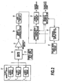
- Fig. 2 is a block diagram for explaining one embodiment of the azimuth measurement device having the 3-axis magnetic sensor according to the invention.
- numeral 10 designates a 3-axis magnetic sensor (geomagnetism detection means); numeral 11 a chopper section; numeral 12 a drive power source section; numeral 13 an amplification section; numeral 14 an A/D conversion section; numeral 15 a data acquisition section; numeral 16 a sensitivity/offset correction calculation section; numeral 17 a specific event detection section; numeral 18 a threshold value parameter setting section; numeral 19 a reliability information calculation section; and numeral 20 an azimuth calculation section.
- the configuration components having the same functions as those of Fig. 1 are designated by the same numerals.
- the geomagnetism outputs measured by the X-axis magnetic sensor 2, the Y-axis magnetic sensor 3 and the Z-axis magnetic sensor 4 of the 3-axis magnetic sensor 10 are amplified by the amplification section 13 through the chopper section 11 driven by the drive power source section 12 and are input to the A/D conversion section 14.
- the X-axis magnetic sensor 2, the Y-axis magnetic sensor 3 and the Z-axis magnetic sensor 4 are provided for detecting the geomagnetism and are preferably Hall elements of a compound semiconductor such as InSb, InAs or GaAs.
- the chopper section 11 switches terminals for driving the X-axis magnetic sensor 2, the Y-axis magnetic sensor 3 and the Z-axis magnetic sensor 4, and applies the drive voltage output from the drive power source section 12 to the X-axis magnetic sensor 2, the Y-axis magnetic sensor 3 and the Z-axis magnetic sensor 4.
- This chopper section 11 can use a 90-degree chopper drive or a 360-degree chopper drive, for example.
- the 360-degree chopper drive can cancel not only the offset terms of the Hall elements. themselves, as contained in the outputs of the X-axis magnetic sensor 2, the Y-axis magnetic sensor 3 and the Z-axis magnetic sensor 4, but also the electric offset terms by the amplifier itself of the subsequent step.
- the signals output from the X-axis magnetic sensor 2, the Y-axis magnetic sensor 3 and the Z-axis magnetic sensor 4 are amplified by the amplifier 13, and the amplified output values are converted from analog signals into digital signals by the A/D conversion section 14. After converted into the digital signals, the converted data is acquired/stored, and is then output, if necessary, through the data acquisition section 15 and input to the sensitivity/offset correction calculation section 16.
- the offsets and the sensitivity correction coefficients of the X-, Y- and Z-axis magnetic sensors 2, 3 and 4 are calculated to compensate the X-, Y- and Z-axis magnetically measured data are corrected on the basis of the offsets and the sensitivity correction coefficients calculated.
- the aforementioned sensitivity/offset correction calculation section 16 selects the acquisition data in accordance with the data measuring conditions. On the basis of the offsets and the selected data group, the sensitivity/offset correction calculation section 16 calculates the sensitivity correction coefficient of the magnetic sensors, the reference point, the radius of the sphere having the magnetic data distributed, the offsets, and the magnitude of the geomagnetism (i.e., the distance of the acquired data to the reference point). On the basis of the sensitivity correction coefficient calculated, moreover, the sensitivity/offset correction calculation section 16 corrects the measured magnetism data.
- the signal from the specific event detection section 17 is input to the threshold value parameter setting section 18.
- This threshold value parameter setting section 18 sets the acceptance threshold value, the data measurement parameters and the offset calculation parameters from any of the first, second and third pieces of reliability information or their combination.
- the output of this threshold value parameter setting section 18 is input to the sensitivity/offset correction calculation section 16 and the reliability information calculation section 19.
- This reliability information calculation section 19 calculates not only the first and second pieces of reliability information from the predetermined number of the recent acquired data and/or from the predetermined number of the recent offset but also the third reliability information from a data measurement parameter and an offset measurement calculation parameter.
- the reliability information is output from the reliability information calculation section 19.
- This reliability information is further output to the sensitivity/offset correction calculation section 16.
- This sensitivity/offset correction calculation section 16 compares the threshold value input from the threshold value parameter setting section 18 and the reliability information from the reliability information calculation section 19 thereby to evaluate whether the calculated offset is to be adopted, and outputs the adopted offset to the azimuth calculation section 20.
- the magnetism components other than the geomagnetism are acquired (as referred to PCT Laid-Open WO2004/003476 ) by applying the magnetic data group of N ( ⁇ 4) acquired by the azimuth measurement device to the spherical surface thereby to determine the center coordinates (e.g., the offset and the reference point) of the sphere.
- the radius of the sphere determined at the same time indicates the magnitude of the geomagnetism.
- the magnetism data is the 2- or 3-axis measured values acquired by one measurement by the magnetic sensor
- the magnetism data group is a set of 2- or 3-axis measured values acquired by several measurements by the magnetic sensor.
- Fig. 3 is a diagram showing the dispersion of data composing a group of magnetically measured data and the dispersion of the reference point.
- the reference point may be caused to contain a large error by the distribution of the data composing the measured magnetism data group.
- the measured data group is absent or when the existing data group is ineffective, as just after the power up or as the peripheral magnetic state highly changes, a long time may be taken till the correct value is calculated, if the value for deciding the offset update is excessively small (or strict). It is, therefore, necessary to set the acceptance threshold high (or loose) at first. It is confirmed that the data composing the measured magnetism data group are properly distributed on the spherical surface, and that the fluctuation width of the reference point to be calculated becomes small.
- the dispersion may use an index capable of expressing the data distribution, such as the difference between the maximum and the minimum of each axis of the magnetic data group or the standard deviation of the measured values of each axis.
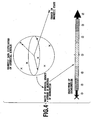
- Fig. 4 is a diagram showing the change in a magnetic state, the magnitudes of the geomagnetism and the classification of the geomagnetism magnitudes.
- the magnitudes of the geomagnetism vectors calculated on the basis of the center coordinates used till then takes values largely different from the radius of the spherical surface.
- the magnetism data group acquired has to be discarded, and the center coordinates and the radius have to be recalculated with the data group newly acquired (alternatively, the center coordinates may also be smoothly updated by calculating the center coordinates with the magnetic data group acquired till then).
- the method of comparing the distance of the magnetic data calculated from the reference point and the radius of the sphere adopted, or the method of comparing the distance of the magnetic data calculated from the reference point and the magnitude (e.g., 45 to 50 micro-teslas ( ⁇ T)) of the geomagnetism may be anticipated.
- the acceptance threshold for determining the highly accurate offset immediately before the change in the magnetic state is loosened to an acceptance threshold for determining the offset more quickly. Then, the acceptance threshold can respond to the change in the offset quickly. It is also frequently effective to return the acceptance threshold to an initial value.
- the means for knowing that the magnetic state has changed should not be limited to the calculation of the magnitudes of the geomagnetism (e.g., the comparison with the absolute value of the geomagnetism or the radius) but also the angle of depression (geomagnetic inclination) ( Fig. 8 ), the range of an A/D value, the range of dispersion of the reference point, the difference from the reference point calculated immediately before, or the known event to cause the change in the magnetic state.
- the range of the dispersion of the reference point and the difference of the reference point are calculated by using the reference point which is estimated from the data group containing the magnetic data before and after the change in the magnetism state, so that the detection sensitivity becomes low.
- means for detecting the event can be provided for knowing the change in the magnetic state with an event detection signal.
- the magnetic state changes when the cell-phone is folded.
- some latest cell-phone can use an external memory card for storing image data or music data and may be changed in the magnetic state by inserting/extracting the memory card.
- the cell-phone may be equipped with a button for informing the azimuth measurement device of the change in the magnetic state in accordance with the decision of the user.
- the magnetic detector has temperature characteristics such as those of the Hall element, the offset may also be recalculated in case the temperature change detected is at a predetermined value or higher.
- Fig. 5 is a diagram showing the number of offset calculation point and a calculation accuracy.
- the azimuth measurement device can be controlled according to the change in the environment.
- the parameters are exemplified not only by the number of data composing the magnetism data group for calculating the reference point but also by the minimum change in the continuous magnetism data, the time interval of the magnetism data measurement, the number of reference points for calculating the dispersion of the reference points, the magnetism data judgment time (e.g., a predetermined number A and a predetermined number B), and the amplification of a magnetic sensor amplifier.
- the measured magnetic data output from the magnetic sensor does not change so much.
- the reference point is calculated from the data group composing the magnetism data of a small change, the fluctuation of the data or the influence of noises may become so large as to make the reference point inaccurate. It is, therefore, important for enhancing the accuracy of the offset to evaluate the change of the data output from the magnetic sensor from the data selected and adopted beforehand, thereby to adopt and compose only the data having changed a predetermined value or higher, into the data group. If the threshold value of the change is raised, however, the data is adopted when the azimuth measurement device highly moves so that a long time is taken before the offset is calculated. In short, the data of a small change is also adopted when the offset is to be quickly determined although its reliability is low. But only the data of a large change is adopted when the reliability is to be enhanced although the calculation of the offset takes a long time.
- the measurement time interval of the magnetic data is set as long as possible because it is concerned with the power consumption of the azimuth measurement device.
- the measurement time interval can be shortened to acquire the necessary data for the short time period.
- the dispersion of the reference points estimated is evaluated.
- the number of reference points to be evaluated is desired to be as many as possible. However, the number of reference points to be evaluated has to be as small as possible, when the measured data group is absent or when the existing data group is ineffective as the power up state or as the peripheral magnetic state highly changes.
- the magnetic state suddenly changes and quickly returns to the initial state (as is exemplified by erroneously bringing the magnet close to the azimuth measurement device), it is premature to discard the center coordinates quickly.
- the offset need not be discarded (at the predetermined number A), if the magnitude of the geomagnetism or the like returns to an allowable value within a predetermined time period.
- the acceptance threshold is made strict, awaiting the calculation of a predetermined number or more of the offset at an acceptance threshold.
- the value of the offset in the case of a loose acceptance threshold is low in reliability so that the adoption of the mistaken offset can be prevented by a method of averaging a plurality of offsets.
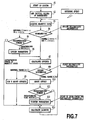
- Fig. 7 is a diagram showing a flow chart for explaining the offset updating.
- a parameter JM indicates a geomagnetism threshold value
- a parameter JO an offset threshold value
- parameters k and 1 the numbers acceptance thresholds unchanged.
- the system is started up (at S1), and the initial values of parameters are set (at S2).
- the magnetic data is acquired (at S3) to evaluate (at S4) (i.e., for the second reliability information) whether the geomagnetism is normal or abnormal.
- the predetermined number A(k) is decided (at S5). If the number A(k) is a predetermined time period or longer, the parameters are loosened (at S6). If shorter than the predetermined time period, the routine shifts to the azimuth calculation (at S13).
- the reference point calculation is made (at S7) to evaluate (at S8) (i.e., the first reliability information) whether or not the reference points are dispersed.
- the reference points are not adopted (at S9), if this dispersion is within the abnormal range, but adopted (at S10) as the offsets if within the normal range.
- the predetermined number B(1) is evaluated (at S11).
- the parameters are tightened (at S12) (i.e., the first to third pieces of reliability information), and the azimuth calculation is made (at S13), if the time period is at a predetermined value or longer.
- the azimuth calculation is made (at S13) as it is, and the routine returns to the aforementioned step 3, if the time period is shorter.
- the magnitude of the geomagnetism can be used as an indicator of reliability of the offset.
- the radius of the sphere having the magnetic data distributed is calculated.
- the radius of the sphere is outside of the range of the acceptance threshold set from the magnitude (e.g. , 45 to 50 micro-teslas in Japan) of the ordinarily estimated geomagnetism, the offset can be unadopted because of the low reliability of the offset value.
- the acceptance threshold and the parameters such as the data measurement conditions or the offset calculating conditions may be either prepared beforehand as a table, as shown in Fig. 6 , or calculated from the magnitude of the geomagnetism or the dispersion value of the reference points by numerical equations.
- the updating sequence may be determined either by updating the states one by one or by skipping the several states.
- the acceptance thresholds are narrowed, for example, it is proper to narrow the acceptance thresholds and the parameters step by step.
- the reliability is seemed to be low when the calculated magnitude of the geomagnetism is abnormally high, it is proper to loosen the acceptance thresholds and the parameters all at once to their initial values and to calculate the offsets again.
- it is arbitrary to narrow the acceptance thresholds and the parameters by the steps.
- the azimuth measurement device can output the acceptance thresholds (i.e., the first reliability and the second reliability) occasionally used and the measurement parameters (i.e., the data measurement conditions and the offset information calculation conditions) that is the third reliability information
- the user or the using device of the azimuth measurement device can know the accuracy and the reliability of the azimuth to be output.
- the four states expressing the reliability exist, for example, as shown in the table of Fig. 6 , the user is enabled to know the accuracy and the reliability of the azimuth indicated by the azimuth measurement device, easily by indicating those states in numerals or colors in the display section of the azimuth measurement device.
- another system using the output of the azimuth measurement device can know the accuracy and reliability of the azimuth and can also operate a high-order application in accordance with the accuracy and the reliability of the azimuth.
- the probability of giving erroneous azimuth information to the user can be lowered to prevent the confusion of the user either by making counter-measures of neither updating the display of the azimuth nor turning the map.
- the change in the peripheral magnetic condition can be known, as shown in Fig. 8 .
- the function to monitor the geomagnetic inclination angle moreover, whether or not the azimuth measurement device is in the specified position can be decided in dependence upon whether or not the geomagnetic inclination angle calculated from the obtained output data is within the normal range (e.g., about 45 degrees in Japan), when the azimuth measurement device requests the user for the predetermined (e.g., horizontal) position.
- the azimuth measurement device not having the function to measure the tilting angle of the device when the azimuth is to be measured so that the measurement accuracy deteriorates unless it is held in the horizontal direction, whether or not the azimuth measurement device is horizontal is discriminated by the aforementioned means thereby to evaluate the reliability of the data.
- the user can be instructed to place the azimuth measurement device horizontally.
- the first reliability information is the range of the dispersion of the reference points, the dispersion (i.e., the dispersion in the two-dimensional or three-dimensional space) of data composing the measured data group, and the distances from the output data to the reference points.
- the predetermined number A is exemplified by the number or time length which is decided with a tendency to measure the dispersion of the reference points and the dispersion of the data composing the measured data group either a plurality of times or for a predetermined time period.
- the second reliability information is exemplified by the magnitude, geomagnetic inclination angle or A/D value of the geomagnetism vector calculated from the adopted reference points and the latest measured data.
- the predetermined number B is exemplified by the number or time length which is decided with a tendency to measure the magnitude of the geomagnetism vector, the geomagnetic inclination angle, the A/D value, and the dispersion of the recent reference point.
- the data measurement conditions and the offset information conditions are exemplified by the number of data composing the magnetic data group for calculating the reference points, the minimum change in the sequential output data, the output data measurement time interval, the number of reference points for calculating the dispersion of reference points, and the aforementioned predetermined numbers A and B.
- Fig. 9 is a block diagram for explaining another embodiment of the azimuth measurement device having the 3-axis magnetic sensor according to the invention.
- numeral 21 designates a magnetic environment change detection section, and the remaining components having the same functions as those of Fig. 2 are designated by the same numerals.
- the magnetic environment change detection section 21 is not only connected with the data acquisition section 15 but also connected individually with the sensitivity/offset correction calculation section 16, the threshold value parameter setting section 18 and the reliability information calculation section 19.
- the magnetic environment change detection section 21 detects it, in case the data acquired by the data acquisition section 15 exceeds a predetermined range, that the magnetic state has changed.
- the threshold value parameter setting section 18 is configured to loosen its acceptance threshold value when the magnetic environment change detection section 21 detects the change of the magnetic environment.
- the magnetic environment change detection section can detect it, in case the data acquired by the data acquisition section exceeds the predetermined range that the magnetic state has changed.
- the present invention relates to an azimuth measurement device and an azimuth measurement method and, more particularly, to an azimuth measurement device and an azimuth measurement method for calculating an offset quickly or highly accurately from the magnetic data group acquired for measuring an azimuth, in accordance with the situations.
Landscapes
- Physics & Mathematics (AREA)
- Engineering & Computer Science (AREA)
- Radar, Positioning & Navigation (AREA)
- Remote Sensing (AREA)
- General Physics & Mathematics (AREA)
- Electromagnetism (AREA)
- Condensed Matter Physics & Semiconductors (AREA)
- Measuring Magnetic Variables (AREA)
- Navigation (AREA)
- Hall/Mr Elements (AREA)
- Variable-Direction Aerials And Aerial Arrays (AREA)
- Paper (AREA)
Abstract
Description
- The present invention relates to an azimuth measurement device and an azimuth measurement method and, more particularly, to an azimuth measurement device and an azimuth measurement method for calculating an offset quickly or highly accurately from the magnetic data group acquired for measuring an azimuth, in accordance with the situations.
US 2003/0023380 A1 relates to electronic compasses for use in vehicles, in more particular to a method of automatic continuous calibration of an electronic compass for use in a vehicle, wherein the method includes the steps of initializing variables, retrieving sensor readings from at least 2-axis, updating a calibration based on the sensor readings, calculating a first azimuth with the sensor readings, updating a first heading from said first azimuth, and determining if a display needs said updated first heading transferred thereto. - For the azimuth measurement device for detecting the geomagnetism to calculate the azimuth, it is important to discriminate a geomagnetism (i.e., a steady magnetic field) and such a magnetic field other than the geomagnetism as is generated by a magnet or the like fixed in the azimuth measurement device. The magnetic field other than the geomagnetism is calculated as an offset (or a reference point) from a measured magnetic data group by proper means. The geomagnetism can be determined by subtracting that offset from the measured magnetic value.
- This offset highly changes in dependence upon whether a magnetic element (e.g., a memory card) accompanying the azimuth measurement device is mounted or demounted. Alternatively, the user of the azimuth measurement device may evaluate that the calculated value of the offset is improper, and may require a recalculation intentionally.
- As an azimuth measurement device of the prior art, an azimuth measurement device has been proposed in
Patent Document 1. This azimuth measurement device measures the azimuth on the basis of the geomagnetism which is detected by using a Hall element. A corrected value storage section is stored with the reference values of an X-axis Hall element and a Y-axis Hall element. By using the reference values, a correction calculation section corrects the amplified output values of the X-axis Hall element and the Y-axis Hall element, and extracts only the values proportional to the individual axis components of the geomagnetism. - On the other hand,
Patent Document 2 provides an azimuth measurement device, which is made highly accurate by correcting the error of the mounting angle between the direction of the input axis of the geomagnetism sensor and the direction of the reference axis of a position detection device. This azimuth measurement device comprises: a mounting angle correction operation section for performing a mounting angle error correction for geomagnetism data to operate the geomagnetism data corrected; a coordinate transformation circuit for transforming the coordinates of the geomagnetism data by using position data to output the geomagnetism data; and an azimuth calculation circuit for calculating the azimuth on the basis of the geomagnetism data. - Moreover,
Patent Document 3 describes an azimuth measurement device using a geomagnetism sensor. The horizontal component of the geomagnetism is so detected that it is divided into voltage output signals of two components by magnetic detection coils orthogonal to each other. These voltage output signals are input to a microcomputer having signal correction operation means to operate azimuth data to the magnetic north of the geomagnetism. The azimuth measurement device is provided with correction processing means for operating corrected values corresponding to the individual azimuth data from the microcomputer.
On the other hand, azimuth measurement devices described inPatent Document 4,Patent Document 5 and Patent Document 6 are also known in addition to the aforementioned publications. - A device of the prior art of
Patent Document 7 corrects the offset of the magnetic sensor in the azimuth measurement device and is enabled to calculate offset information with respect to the individual axis outputs of a magnetic sensor merely by changing the direction of a mobile telephone arbitrarily. Moreover, the calibration work of the offset is facilitated to lighten the burden on the user at the time when the offset is calibrated. - This application calculates the dispersion of reference points estimated, and discards the estimated reference point in case the dispersion is at a predetermined value or higher. If this predetermined value (as will be called the "acceptance threshold") is set high, an offset of a large error may be calculated. Since the offset is easily updated, it is instantly corrected even if highly changed.
- In case the decided value is small, on the contrary, the offset is hard to update. In case, therefore, an off set of a small error has already been calculated, an estimated offset value of a larger error can be kept highly accurate by discarding it. In case, however, the offset highly changes, a long time is taken till the correct offset is adopted. For these reasons, a plurality of specifications such as the response rate or accuracy required for the azimuth measurement device are hard to satisfy at the same time, if the adoption and discard of the reference point are determined by using one acceptance threshold at all times.
- The present invention has been conceived in view of those problems, and has an object to provide an azimuth measurement device and an azimuth measurement method for calculating a highly accurate offset quickly according to the situations from a magnetic data group acquired for measuring the azimuth.
-
- Patent Document 1: Japanese Patent Application Laid-open No.
2003-065791 - Patent Document 2: Japanese Patent Application Laid-open No.
2003-042766 - Patent Document 3: Japanese Patent Application Laid-open No.
10-132568 (1998 - Patent Document 4: Japanese Patent Application Laid-open No.
61-147104 (1986 - Patent Document 5: Japanese Patent Application Laid-open No.
62-255814 (1987 - Patent Document 6: Japanese Patent Application Laid-open No.
8-105745 (1996 - Patent Document 7: Japanese Patent Application Laid-open No.
2003-035010 - According to the invention, there is provided an azimuth measurement device comprising: 2- or 3-axis geomagnetism detection means for detecting the geomagnetism; output data acquisition means for acquiring several times or more either the 2-axis output data at the time when the direction of the geomagnetism detection means changes or the 3-axis output data at the time when the direction of the geomagnetism detection means changes while keeping the 2-axis detecting directions on a predetermined plane in the three-dimensional space; reference point estimation means for selecting the 2- or 3-axis output data on the basis of predetermined measurement parameters, to determine a reference point either on the two-dimensional coordinate space composed of the selected 2-axis output data or on the three-dimensional coordinate space composed of the selected 3-axis output data, thereby to estimate the coordinates of the reference point by a statistical method so that the dispersion of the distances from the selected 2- or 3-axis output data group to the reference point may be minimized; offset information calculation means for calculating the offset information for the output data of the geomagnetism detection means on the basis of a plurality of reference points estimated by the reference point estimation means; azimuth calculation means for calculating an azimuth from the output data and the offset information; and reliability information calculation means for calculating the reliability information of the offset information according to calculation parameters for calculating the reliability information of predetermined offset information, on the basis of at least one of the 2- or 3-axis output data group and the plural reference points.
- Moreover, it is preferable that the offset information calculation means compares the reliability information with an acceptance threshold value to evaluate whether or not the reliability information is to be adopted as the offset information to be used for the calculation of the azimuth by the azimuth calculation means.
- Moreover, it is more preferable that the acceptance threshold value is changed more strictly as the offset information is adopted a predetermined number of times.
- On the other hand, the azimuth measurement device of the invention is preferred to further comprise a detection section for detecting that the magnetic environment inside and outside of the azimuth measurement device has changed, and that the acceptance threshold value is loosened in case the detection section detects that the magnetic environment has changed.
- The detection section can detect that the magnetic environment has changed, in case the data acquired by the output data acquisition means exceeds a predetermined range.
- It is preferred that an azimuth measurement device of the invention further comprises event detection means for detecting either the change in the environment of the azimuth measurement device or the operation of the operator, and that the acceptance threshold value is changed in case the event occurs.
- It is preferred that the azimuth measurement device of the invention that the acceptance threshold value is changed and that at least one of the measurement parameters and the calculation parameters are changed.
- Here, the reliability information of the offset information contains the information calculated from the dispersion of the plural reference points, the information calculated from the dispersion of the data composing the 2- or 3-axis output data group, and the distance from the 2- or 3-axis output data obtained by the output data acquisition means, to the reference point.
- Moreover, the measurement parameters contain a measurement interval and the number of data for the reference point estimation means to estimate the coordinates of the reference point.
- On the other hand: the measurement parameters contain the variation in data; the variation is the difference between the output data acquired by the output data acquisition means and the data selected by the reference point estimation means; and the reference point estimation means can select the data, of which the variation is at a predetermined value or higher.
- On the other hand, the calculation parameters contain the number of reference points for calculating the dispersion of the reference points.
- The azimuth measurement device of the invention can further comprise output means for outputting at least one of the acceptance threshold value, the measurement parameters and the calculation parameters to the outside.
- Moreover, the azimuth measurement device of the invention is preferred that the geomagnetism detection means acquires 3-axis output data, that the azimuth measurement device further comprises information acquisition means relating to the posture angle of the azimuth measurement device, and geomagnetic inclination angle information calculation means for calculating geomagnetic inclination angle information from the output data, the offset information and the posture angle, that the azimuth calculation means calculates the azimuth of the device from the output data, the offset information, and the information relating to the posture angle, and that the index of reliability of the azimuth to be calculated is calculated from the value of the geomagnetic inclination angle information.
- According to the invention, there is provided an azimuth measurement method comprising: the step of acquiring, by using 2- or 3-axis geomagnetism detection means for detecting the geomagnetism several times or more; either the 2-axis output data at the time when the direction of the geomagnetism detection means changes while keeping the 2-axis detecting directions on a predetermined plane or the 3-axis output data at the time when the direction of the geomagnetism detection means changes in the three-dimensional space; the step of selecting the 2- or 3-axis output data on the basis of predetermined measurement parameters; the step of determining a reference point, either on the two-dimensional coordinate composed of the selected 2-axis output data or on the three-dimensional coordinates composed of the selected 3-axis output data, thereby to estimate the coordinates of the reference point by a statistical method so that the dispersion of the distances from the selected 2- or 3-axis output data group to the reference point may be minimized; the step of calculating the offset information for the output data of the geomagnetism detection means on the basis of the plural reference points estimated; the step of calculating an azimuth from the output data and the offset information; and the step of calculating the reliability information of the offset information according to calculation parameters for calculating the reliability information of predetermined offset information, on the basis of at least one of the 2- or 3-axis output data group and the plural reference points.
- Moreover, the offset information calculation step compares the reliability information with an acceptance threshold value to evaluate whether or not the reliability information is to be adopted as the offset information to be used for the calculation of the azimuth.
- It is more preferable that the acceptance threshold value is changed more strictly as the offset information is adopted a predetermined number of times.
- On the other hand, an azimuth measurement method of the invention is preferred to further comprise: the step of detecting that the magnetic environment inside and outside of the azimuth measurement device has changed; and the step of loosening the acceptance threshold value in case it is detected that the magnetic environment has changed.
- Moreover, an azimuth measurement method of the invention is preferred to further comprise: the step of detecting either the change in the environment of the azimuth measurement device or the operation of the operator; and the step of changing the acceptance threshold value in case the event occurs.
- At this time, it is preferred that the acceptance threshold value is changed, and that at least one of the measurement parameters and the calculation parameters are changed.
- Moreover, the azimuth measurement method of the invention is preferred to further comprise the step of outputting at least one of the acceptance threshold value, the measurement parameters and the calculation parameters to the outside.
- Moreover, it is preferred for the azimuth measurement method of the invention that the geomagnetism detection means acquires 3-axis output data, that the azimuth measurement method further comprises: the step of acquiring information relating to the posture angle of the azimuth measurement device; and the step of calculating geomagnetic inclination angle information from the output data, the offset information and the information relating to the posture angle, that the azimuth calculation step calculates the azimuth of the device from the output data, the offset information, and the information relating to the posture angle, and that the azimuth measurement method further comprises the step of calculating the index of reliability of the azimuth to be calculated is calculated from the value of the geomagnetic inclination angle information.
- According to the azimuth measurement device or the azimuth measurement method of the invention, on the basis of the reliability information calculated by the reliability information calculation means, the acceptance threshold value at the time of calculating the offset information can be gradually tightened. When the quick response of the system is demanded as when it is started up, the calculation accuracy can be enhanced by setting the aforementioned acceptance threshold at a higher (or looser) value at first and by reducing (or tightening) the acceptance threshold gradually. At the same time, the response or measurement accuracy of the system can also be changed according to the situations even if the minimum values of the number or change of the data composing the magnetic data group for calculating the offset.
-
- [
Fig. 1] Fig. 1 is a configuration diagram for explaining one embodiment of an azimuth measurement device having a 3-axis magnetic sensor according to the invention. - [
Fig. 2] Fig. 2 is a block diagram for explaining one embodiment of the azimuth measurement device having the 3-axis magnetic sensor according to the invention. - [
Fig. 3] Fig. 3 is a diagram showing the dispersion of data composing a group of magnetically measured data and the dispersion of a reference point. - [
Fig. 4] Fig. 4 is a diagram showing the change in a magnetic state, the magnitudes of a geomagnetism and the classification of the geomagnetism magnitudes. - [
Fig. 5] Fig. 5 is a diagram showing the number of of f set calculation point and calculation accuracy. - [
Fig. 6] Fig. 6 is a diagram showing an offset updating table. - [
Fig. 7] Fig. 7 is a diagram showing a flow chart for explaining an offset updating. - [
Fig. 8] Fig. 8 is a diagram showing a measured output data distribution when the azimuth measurement device is placed in a horizontal position. - [
Fig. 9] Fig. 9 is a block diagram for explaining another embodiment of the azimuth measurement device having the 3-axis magnetic sensor according to the invention. - Hereinafter, embodiments of the invention are described with reference to the accompanying drawings.
-
Fig. 1 is a configuration diagram for explaining one embodiment of an azimuth measurement device having a 3-axis magnetic sensor according to the invention.Numeral 1 designates an azimuth measurement device; numeral 2 an X-axis magnetic sensor; numeral 3 a Y-axis magnetic sensor; and numeral 4 a Z-axis magnetic sensor. In thisazimuth measurement device 1, as shown inFig. 1 , the X-axismagnetic sensor 2, the Y-axismagnetic sensor 3 and the Z-axismagnetic sensor 4 having sensitive faces directed in their individual directions are arranged to intersect with each other at a right angle. The X-axismagnetic sensor 2 is configured to produce its output Mx; the Y-axismagnetic sensor 3 is configured to produce its output My; and the Z-axismagnetic sensor 4 is configured to produce its output Mz. Here, the magnetic sensors may be any such as a Hall element so long as they can measure the magnetism. -
Fig. 2 is a block diagram for explaining one embodiment of the azimuth measurement device having the 3-axis magnetic sensor according to the invention. InFig. 2 :numeral 10 designates a 3-axis magnetic sensor (geomagnetism detection means); numeral 11 a chopper section; numeral 12 a drive power source section; numeral 13 an amplification section; numeral 14 an A/D conversion section; numeral 15 a data acquisition section; numeral 16 a sensitivity/offset correction calculation section; numeral 17 a specific event detection section; numeral 18 a threshold value parameter setting section; numeral 19 a reliability information calculation section; and numeral 20 an azimuth calculation section. Here, the configuration components having the same functions as those ofFig. 1 are designated by the same numerals. - The geomagnetism outputs measured by the X-axis
magnetic sensor 2, the Y-axismagnetic sensor 3 and the Z-axismagnetic sensor 4 of the 3-axismagnetic sensor 10 are amplified by the amplification section 13 through thechopper section 11 driven by the drivepower source section 12 and are input to the A/D conversion section 14. Here, the X-axismagnetic sensor 2, the Y-axismagnetic sensor 3 and the Z-axismagnetic sensor 4 are provided for detecting the geomagnetism and are preferably Hall elements of a compound semiconductor such as InSb, InAs or GaAs. - The
chopper section 11 switches terminals for driving the X-axismagnetic sensor 2, the Y-axismagnetic sensor 3 and the Z-axismagnetic sensor 4, and applies the drive voltage output from the drivepower source section 12 to the X-axismagnetic sensor 2, the Y-axismagnetic sensor 3 and the Z-axismagnetic sensor 4. Thischopper section 11 can use a 90-degree chopper drive or a 360-degree chopper drive, for example. The 360-degree chopper drive can cancel not only the offset terms of the Hall elements. themselves, as contained in the outputs of the X-axismagnetic sensor 2, the Y-axismagnetic sensor 3 and the Z-axismagnetic sensor 4, but also the electric offset terms by the amplifier itself of the subsequent step. - The signals output from the X-axis
magnetic sensor 2, the Y-axismagnetic sensor 3 and the Z-axismagnetic sensor 4 are amplified by the amplifier 13, and the amplified output values are converted from analog signals into digital signals by the A/D conversion section 14. After converted into the digital signals, the converted data is acquired/stored, and is then output, if necessary, through thedata acquisition section 15 and input to the sensitivity/offsetcorrection calculation section 16. On the basis of the measured magnetism data group from thedata acquisition section 15, the offsets and the sensitivity correction coefficients of the X-, Y- and Z-axismagnetic sensors azimuth calculation section 16 so that their azimuth information is output. The method for the azimuth operation can be exemplified by the method which is disclosed in our prior application ofPCT Laid-Open Application W02004/003476 . - On the basis of the data acquired from the
data acquisition section 15, the aforementioned sensitivity/offsetcorrection calculation section 16 selects the acquisition data in accordance with the data measuring conditions. On the basis of the offsets and the selected data group, the sensitivity/offsetcorrection calculation section 16 calculates the sensitivity correction coefficient of the magnetic sensors, the reference point, the radius of the sphere having the magnetic data distributed, the offsets, and the magnitude of the geomagnetism (i.e., the distance of the acquired data to the reference point). On the basis of the sensitivity correction coefficient calculated, moreover, the sensitivity/offsetcorrection calculation section 16 corrects the measured magnetism data. - On the other hand, the signal from the specific
event detection section 17 is input to the threshold valueparameter setting section 18. This threshold valueparameter setting section 18 sets the acceptance threshold value, the data measurement parameters and the offset calculation parameters from any of the first, second and third pieces of reliability information or their combination. The output of this threshold valueparameter setting section 18 is input to the sensitivity/offsetcorrection calculation section 16 and the reliabilityinformation calculation section 19. This reliabilityinformation calculation section 19 calculates not only the first and second pieces of reliability information from the predetermined number of the recent acquired data and/or from the predetermined number of the recent offset but also the third reliability information from a data measurement parameter and an offset measurement calculation parameter. The reliability information is output from the reliabilityinformation calculation section 19. - This reliability information is further output to the sensitivity/offset
correction calculation section 16. This sensitivity/offsetcorrection calculation section 16 compares the threshold value input from the threshold valueparameter setting section 18 and the reliability information from the reliabilityinformation calculation section 19 thereby to evaluate whether the calculated offset is to be adopted, and outputs the adopted offset to theazimuth calculation section 20. - The magnetism components other than the geomagnetism (i.e., the steady magnetic field) are acquired (as referred to
PCT Laid-Open WO2004/003476 ) by applying the magnetic data group of N (≥ 4) acquired by the azimuth measurement device to the spherical surface thereby to determine the center coordinates (e.g., the offset and the reference point) of the sphere. The radius of the sphere determined at the same time indicates the magnitude of the geomagnetism. Here, the magnetism data is the 2- or 3-axis measured values acquired by one measurement by the magnetic sensor, and the magnetism data group is a set of 2- or 3-axis measured values acquired by several measurements by the magnetic sensor. -
Fig. 3 is a diagram showing the dispersion of data composing a group of magnetically measured data and the dispersion of the reference point.
The reference point may be caused to contain a large error by the distribution of the data composing the measured magnetism data group. When the measured data group is absent or when the existing data group is ineffective, as just after the power up or as the peripheral magnetic state highly changes, a long time may be taken till the correct value is calculated, if the value for deciding the offset update is excessively small (or strict). It is, therefore, necessary to set the acceptance threshold high (or loose) at first. It is confirmed that the data composing the measured magnetism data group are properly distributed on the spherical surface, and that the fluctuation width of the reference point to be calculated becomes small. After this confirmation, the accuracy of the offset to be calculated can be enhanced, if the acceptance threshold is made gradually small (or strict ). The dispersion may use an index capable of expressing the data distribution, such as the difference between the maximum and the minimum of each axis of the magnetic data group or the standard deviation of the measured values of each axis. -
Fig. 4 is a diagram showing the change in a magnetic state, the magnitudes of the geomagnetism and the classification of the geomagnetism magnitudes.
In case the peripheral magnetic state highly changes, the followings are happen. The magnitudes of the geomagnetism vectors calculated on the basis of the center coordinates used till then takes values largely different from the radius of the spherical surface. In this case, the magnetism data group acquired has to be discarded, and the center coordinates and the radius have to be recalculated with the data group newly acquired (alternatively, the center coordinates may also be smoothly updated by calculating the center coordinates with the magnetic data group acquired till then). - As the means for knowing the change in the magnetic state, the method of comparing the distance of the magnetic data calculated from the reference point and the radius of the sphere adopted, or the method of comparing the distance of the magnetic data calculated from the reference point and the magnitude (e.g., 45 to 50 micro-teslas (µT)) of the geomagnetism may be anticipated.
- When the change in the magnetic state occurs, the offset largely changes, and the offset adopted cannot be frequently utilized. In this case, the acceptance threshold for determining the highly accurate offset immediately before the change in the magnetic state is loosened to an acceptance threshold for determining the offset more quickly. Then, the acceptance threshold can respond to the change in the offset quickly. It is also frequently effective to return the acceptance threshold to an initial value.
- The means for knowing that the magnetic state has changed should not be limited to the calculation of the magnitudes of the geomagnetism (e.g., the comparison with the absolute value of the geomagnetism or the radius) but also the angle of depression (geomagnetic inclination) (
Fig. 8 ), the range of an A/D value, the range of dispersion of the reference point, the difference from the reference point calculated immediately before, or the known event to cause the change in the magnetic state. However, the range of the dispersion of the reference point and the difference of the reference point are calculated by using the reference point which is estimated from the data group containing the magnetic data before and after the change in the magnetism state, so that the detection sensitivity becomes low. When a known event for causing the change in the magnetic state exists, means for detecting the event can be provided for knowing the change in the magnetic state with an event detection signal. - In case the azimuth measurement device is packaged in a foldable cell-phone, for example, the magnetic state changes when the cell-phone is folded. Moreover, some latest cell-phone can use an external memory card for storing image data or music data and may be changed in the magnetic state by inserting/extracting the memory card. The cell-phone may be equipped with a button for informing the azimuth measurement device of the change in the magnetic state in accordance with the decision of the user. In case the magnetic detector has temperature characteristics such as those of the Hall element, the offset may also be recalculated in case the temperature change detected is at a predetermined value or higher.
-
Fig. 5 is a diagram showing the number of offset calculation point and a calculation accuracy.
When the number of data composing the magnetic data group for calculating the reference point is changed simultaneously as the acceptance threshold is changed, the response rate and the calculation accuracy can be better controlled. Just after the power-up, the number of data composing the magnetism data group is reduced to make the response better although the calculation accuracy is rough, so that the calculation accuracy is enhanced by tightening the acceptance threshold gradually and by enlarging the number of data composing the magnetic data group. - By thus updating the acceptance threshold and changing the parameters for the data measuring conditions or the offset calculating conditions, the azimuth measurement device can be controlled according to the change in the environment. The parameters are exemplified not only by the number of data composing the magnetism data group for calculating the reference point but also by the minimum change in the continuous magnetism data, the time interval of the magnetism data measurement, the number of reference points for calculating the dispersion of the reference points, the magnetism data judgment time (e.g., a predetermined number A and a predetermined number B), and the amplification of a magnetic sensor amplifier.
- In case the position of the azimuth measurement device does not change so much in the two-dimensional or three-dimensional space, the measured magnetic data output from the magnetic sensor does not change so much. Even if the reference point is calculated from the data group composing the magnetism data of a small change, the fluctuation of the data or the influence of noises may become so large as to make the reference point inaccurate. It is, therefore, important for enhancing the accuracy of the offset to evaluate the change of the data output from the magnetic sensor from the data selected and adopted beforehand, thereby to adopt and compose only the data having changed a predetermined value or higher, into the data group. If the threshold value of the change is raised, however, the data is adopted when the azimuth measurement device highly moves so that a long time is taken before the offset is calculated. In short, the data of a small change is also adopted when the offset is to be quickly determined although its reliability is low. But only the data of a large change is adopted when the reliability is to be enhanced although the calculation of the offset takes a long time.
- The measurement time interval of the magnetic data is set as long as possible because it is concerned with the power consumption of the azimuth measurement device. When the offset is to be quickly calculated, however, the measurement time interval can be shortened to acquire the necessary data for the short time period.
- In order to evaluate the reliability of the offset, the dispersion of the reference points estimated is evaluated. The number of reference points to be evaluated is desired to be as many as possible. However, the number of reference points to be evaluated has to be as small as possible, when the measured data group is absent or when the existing data group is ineffective as the power up state or as the peripheral magnetic state highly changes.
- In case the magnetic state suddenly changes and quickly returns to the initial state (as is exemplified by erroneously bringing the magnet close to the azimuth measurement device), it is premature to discard the center coordinates quickly. The offset need not be discarded (at the predetermined number A), if the magnitude of the geomagnetism or the like returns to an allowable value within a predetermined time period.
- In another method (at the predetermined number B), the acceptance threshold is made strict, awaiting the calculation of a predetermined number or more of the offset at an acceptance threshold. The value of the offset in the case of a loose acceptance threshold is low in reliability so that the adoption of the mistaken offset can be prevented by a method of averaging a plurality of offsets.
-
Fig. 7 is a diagram showing a flow chart for explaining the offset updating.
InFig. 7 : a parameter JM indicates a geomagnetism threshold value; a parameter JO an offset threshold value; and parameters k and 1 the numbers acceptance thresholds unchanged. - Hereinafter, the flow chart shown in
Fig. 7 is described.
At first, the system is started up (at S1), and the initial values of parameters are set (at S2). Next, the magnetic data is acquired (at S3) to evaluate (at S4) (i.e., for the second reliability information) whether the geomagnetism is normal or abnormal. In the abnormal case, the predetermined number A(k) is decided (at S5). If the number A(k) is a predetermined time period or longer, the parameters are loosened (at S6). If shorter than the predetermined time period, the routine shifts to the azimuth calculation (at S13). - In case the geomagnetism is normal, the reference point calculation is made (at S7) to evaluate (at S8) (i.e., the first reliability information) whether or not the reference points are dispersed. The reference points are not adopted (at S9), if this dispersion is within the abnormal range, but adopted (at S10) as the offsets if within the normal range. Next, the predetermined number B(1) is evaluated (at S11). The parameters are tightened (at S12) (i.e., the first to third pieces of reliability information), and the azimuth calculation is made (at S13), if the time period is at a predetermined value or longer. The azimuth calculation is made (at S13) as it is, and the routine returns to the
aforementioned step 3, if the time period is shorter. - The magnitude of the geomagnetism can be used as an indicator of reliability of the offset. When the offset is calculated, the radius of the sphere having the magnetic data distributed is calculated. In case, however, the radius of the sphere is outside of the range of the acceptance threshold set from the magnitude (e.g. , 45 to 50 micro-teslas in Japan) of the ordinarily estimated geomagnetism, the offset can be unadopted because of the low reliability of the offset value.
- The acceptance threshold and the parameters such as the data measurement conditions or the offset calculating conditions may be either prepared beforehand as a table, as shown in
Fig. 6 , or calculated from the magnitude of the geomagnetism or the dispersion value of the reference points by numerical equations. In case the table is prepared, moreover, the updating sequence may be determined either by updating the states one by one or by skipping the several states. - When the acceptance thresholds are narrowed, for example, it is proper to narrow the acceptance thresholds and the parameters step by step. In case the reliability is seemed to be low when the calculated magnitude of the geomagnetism is abnormally high, it is proper to loosen the acceptance thresholds and the parameters all at once to their initial values and to calculate the offsets again. As the case may be, it is arbitrary to narrow the acceptance thresholds and the parameters by the steps.
- If the azimuth measurement device can output the acceptance thresholds (i.e., the first reliability and the second reliability) occasionally used and the measurement parameters (i.e., the data measurement conditions and the offset information calculation conditions) that is the third reliability information, the user or the using device of the azimuth measurement device can know the accuracy and the reliability of the azimuth to be output. In case the four states expressing the reliability exist, for example, as shown in the table of
Fig. 6 , the user is enabled to know the accuracy and the reliability of the azimuth indicated by the azimuth measurement device, easily by indicating those states in numerals or colors in the display section of the azimuth measurement device. - Alternatively, another system using the output of the azimuth measurement device can know the accuracy and reliability of the azimuth and can also operate a high-order application in accordance with the accuracy and the reliability of the azimuth.
- Specifically, in case the reliability of the calculated azimuth is low in the application for turning the map display in accordance with the azimuth information, the probability of giving erroneous azimuth information to the user can be lowered to prevent the confusion of the user either by making counter-measures of neither updating the display of the azimuth nor turning the map.
- By monitoring not only the magnitude of the geomagnetism but also the angle of depression, for example, the change in the peripheral magnetic condition can be known, as shown in
Fig. 8 . With the function to monitor the geomagnetic inclination angle, moreover, whether or not the azimuth measurement device is in the specified position can be decided in dependence upon whether or not the geomagnetic inclination angle calculated from the obtained output data is within the normal range (e.g., about 45 degrees in Japan), when the azimuth measurement device requests the user for the predetermined (e.g., horizontal) position. - In the case of the azimuth measurement device not having the function to measure the tilting angle of the device when the azimuth is to be measured so that the measurement accuracy deteriorates unless it is held in the horizontal direction, whether or not the azimuth measurement device is horizontal is discriminated by the aforementioned means thereby to evaluate the reliability of the data. In an alternative method, the user can be instructed to place the azimuth measurement device horizontally.
- Here, the first reliability information is the range of the dispersion of the reference points, the dispersion (i.e., the dispersion in the two-dimensional or three-dimensional space) of data composing the measured data group, and the distances from the output data to the reference points. Moreover, the predetermined number A is exemplified by the number or time length which is decided with a tendency to measure the dispersion of the reference points and the dispersion of the data composing the measured data group either a plurality of times or for a predetermined time period. On the other hand, the second reliability information is exemplified by the magnitude, geomagnetic inclination angle or A/D value of the geomagnetism vector calculated from the adopted reference points and the latest measured data. Moreover, the predetermined number B is exemplified by the number or time length which is decided with a tendency to measure the magnitude of the geomagnetism vector, the geomagnetic inclination angle, the A/D value, and the dispersion of the recent reference point. Moreover, the data measurement conditions and the offset information conditions (i.e., the parameters) are exemplified by the number of data composing the magnetic data group for calculating the reference points, the minimum change in the sequential output data, the output data measurement time interval, the number of reference points for calculating the dispersion of reference points, and the aforementioned predetermined numbers A and B.
-
Fig. 9 is a block diagram for explaining another embodiment of the azimuth measurement device having the 3-axis magnetic sensor according to the invention. InFig. 9 , numeral 21 designates a magnetic environment change detection section, and the remaining components having the same functions as those ofFig. 2 are designated by the same numerals. - The magnetic environment
change detection section 21 is not only connected with thedata acquisition section 15 but also connected individually with the sensitivity/offsetcorrection calculation section 16, the threshold valueparameter setting section 18 and the reliabilityinformation calculation section 19. The magnetic environmentchange detection section 21 detects it, in case the data acquired by thedata acquisition section 15 exceeds a predetermined range, that the magnetic state has changed. The threshold valueparameter setting section 18 is configured to loosen its acceptance threshold value when the magnetic environmentchange detection section 21 detects the change of the magnetic environment. - With this configuration, the magnetic environment change detection section can detect it, in case the data acquired by the data acquisition section exceeds the predetermined range that the magnetic state has changed.
- The present invention relates to an azimuth measurement device and an azimuth measurement method and, more particularly, to an azimuth measurement device and an azimuth measurement method for calculating an offset quickly or highly accurately from the magnetic data group acquired for measuring an azimuth, in accordance with the situations.
Claims (21)
- An azimuth measurement device for calculating an azimuth and an offset from a magnetic data group acquired for measuring an azimuth, comprising:2- or 3-axis geomagnetism detection means (10) for detecting the geomagnetism;output data acquisition means (15) for acquiring a plurality of times, either the 2-axis output data at the time when the direction of said geomagnetism detection means changes while keeping said 2-axis detecting directions on a predetermined plane or the 3-axis output data at the time when the direction of said geomagnetism detection means changes in the three-dimensional space;reference point estimation means (16) for calculating the coordinates of a reference point by a statistical method so that the dispersion of the distances from selected 2- or 3-axis output data group to the reference point can be minimized; said reference point estimation means also being adapted for selecting said 2- or 3-axis output data on the basis of predetermined measurement parameters, for determining a reference point either on the two-dimensional coordinate composed of said selected 2-axis output data or on the three-dimensional coordinates composed of said selected 3-axis output data,offset correction calculation means (16) for calculating the offset information for the output data of said geomagnetism detection means on the basis of a plurality of corrected reference points;azimuth calculation means (20) for calculating an azimuth from said output data and said offset information; andreliability information calculation means (19) for calculating the reliability information of said offset information according to calculation parameters for calculating a first reliability information of predetermined offset information, on the basis of at least one of said 2- or 3-axis output data group and said reference points;wherein said offset correction calculation means is adapted to compare said reliability information with an acceptance threshold value to evaluate whether or not said calculated offset information is to be adopted as the offset information to be used for the calculation of the azimuth by said azimuth calculation means; andwherein said acceptance threshold value is changed as said offset information is adopted a plurality of times.
- An azimuth measurement device according to claim 1, wherein at least one of said measurement parameters and said calculation parameters are changed, when said acceptance threshold value is changed.
- An azimuth measurement device according to claim 1 or 2, wherein the reliability information of said offsets information contains reliability information calculated from the dispersion of the reference points.
- An azimuth measurement device according to claim 1 or 2, wherein the reliability information of said offset information contains reliability information calculated from the dispersion of the data composing said 2- or 3-axis output data group.
- An azimuth measurement device according to claim 1 or 2, wherein the reliability information of said offsets information contains the information of distance from the 2- or 3-axis output data obtained by said output data acquisition means, to the reference point.
- An azimuth measurement device according to claim 1 or 2, wherein said measurement parameters contain a measurement interval.
- An azimuth measurement device according to claim 1 or 2,
wherein said measurement parameters contain the change in data,
wherein said change is the difference between the output data acquired by said output data acquisition means and the data selected by said reference point estimation means for calculating said reference point, and
wherein said reference point estimation is adapted to select the data of which said variation is at a predetermined value or higher. - An azimuth measurement device according to claim 1 or 2, wherein said measurement parameters contain the number of data for said reference point estimation means to estimate the coordinates of the reference point.
- An azimuth measurement device according to claim 1 or 2, wherein said calculation parameters contain the number of reference points for calculating the dispersion of said reference points.
- An azimuth measurement device according to any of claims 1 to 9, further comprising output means for outputting at least one of said acceptance threshold value, said measurement parameters and said calculation parameters.
- An azimuth measurement method for calculating an offset from a magnetic data group acquired for measuring an azimuth, comprising:the step of acquiring, by using 2- or 3-axis geomagnetism detection means for detecting the geomagnetism, either the 2-axis output data at the time when the direction of said geomagnetism detection means changes or the 3-axis output data at the time when the direction of said geomagnetism detection means changes in the three-dimensional space, a plurality of times while keeping said 2-axis detecting directions on a predetermined plane;the step of selecting said 2- or 3-axis output data on the basis of predetermined measurement parameters;the step of determining a reference point either on the two-dimensional coordinate composed of said selected 2-axis output data or on the three-dimensional coordinates composed of said selected 3-axis output data, thereby to correct the coordinates of the reference point by a statistical method so that the dispersion of the distances from said selected 2- or 3-axis output data group to the reference point can be minimized;the step of calculating the offset information for the output data of said geomagnetism detection means on the basis of said corrected reference points;the step of calculating an azimuth from said output data and said offset information; andthe step of calculating the reliability information of said offset information according to calculation parameters for calculating the reliability information of predetermined offset information, on the basis of at least one of said 2- or 3-axis output data group and said reference points;wherein said offset information calculation step compares said reliability information with an acceptance threshold value to evaluate whether or not said calculated offset information is to be adopted as the offset information to be used for the calculation of the azimuth; andwherein said acceptance threshold value is changed as said offset information is adopted a plurality of times.
- An azimuth measurement method according to claim 11,
wherein said acceptance threshold value is changed, and
wherein at least one of said measurement parameters and said calculation parameters are changed. - An azimuth measurement method according to claim 11 or 12, wherein the reliability information of said offset information contains reliability information calculated from the dispersion of the reference points.
- An azimuth measurement method according to claim 11 or 12, wherein the reliability information of said offset information contains reliability information calculated from the dispersion of the data composing said 2- or 3-axis output data group.
- An azimuth measurement method according to claim 11 or 12, wherein the reliability information of said offset information contains information of distance from the 2- or 3-axis output data obtained by said output data acquisition means, to the reference point.
- An azimuth measurement method according to claim 11 or 12, wherein said measurement parameters contain a measurement interval.
- An azimuth measurement method according to claim 11 or 12,
wherein said measurement parameters contain the change in data,
wherein said change is the difference between the output data acquired by said acquiring step and the data selected by said reference point determining step, and
wherein said reference point determining step selects the data of which said change is at a predetermined value or higher. - An azimuth measurement method according to claim 11 or 12, wherein said measurement parameters contain the number of data for estimating the coordinates of the reference point.
- An azimuth measurement method according to claim 11 or 12, wherein said calculation parameters contain the number of reference points for calculating the dispersion of said reference points.
- An azimuth measurement method according to claim 11 or 12, further comprising the step of outputting at least one of said acceptance threshold value, said measurement parameters and said calculation parameters.
- An azimuth measurement method according to any of claims 11 to 20,
wherein said geomagnetism detection step acquires 3-axis output data,
the method further comprising:the step of acquiring information relating to the posture angle of the azimuth measurement device, andthe step of calculating geomagnetic inclination angle information from said output data, said offset information and the information relating to the posture angle,wherein said azimuth calculation step calculates the azimuth of the device form said output data, said offset information, and the information relating to said posture angle, andthe method further comprising the step of calculating the index of reliability of the azimuth by using the value of said geomagnetic inclination angle information.
Applications Claiming Priority (2)
| Application Number | Priority Date | Filing Date | Title |
|---|---|---|---|
| JP2003270821 | 2003-07-03 | ||
| PCT/JP2004/009324 WO2005003683A1 (en) | 2003-07-03 | 2004-07-01 | Azimuth measurement device and azimuth measurement method |
Publications (3)
| Publication Number | Publication Date |
|---|---|
| EP1643212A1 EP1643212A1 (en) | 2006-04-05 |
| EP1643212A4 EP1643212A4 (en) | 2008-04-23 |
| EP1643212B1 true EP1643212B1 (en) | 2011-04-06 |
Family
ID=33562626
Family Applications (1)
| Application Number | Title | Priority Date | Filing Date |
|---|---|---|---|
| EP04746793A Expired - Lifetime EP1643212B1 (en) | 2003-07-03 | 2004-07-01 | Azimuth measurement device and azimuth measurement method |
Country Status (8)
| Country | Link |
|---|---|
| US (1) | US7340362B2 (en) |
| EP (1) | EP1643212B1 (en) |
| JP (1) | JP4644126B2 (en) |
| KR (2) | KR20060036078A (en) |
| CN (1) | CN1816730B (en) |
| AT (1) | ATE504804T1 (en) |
| DE (1) | DE602004032141D1 (en) |
| WO (1) | WO2005003683A1 (en) |
Families Citing this family (41)
| Publication number | Priority date | Publication date | Assignee | Title |
|---|---|---|---|---|
| ATE449952T1 (en) * | 2003-12-22 | 2009-12-15 | Asahi Kasei Emd Corp | AZIMUTH MEASURING DEVICE |
| DE102005017320A1 (en) * | 2004-04-17 | 2005-11-10 | Vectronix Ag | A method of estimating the accuracy of azimuth orientations and portable targeting apparatus |
| WO2006011276A1 (en) * | 2004-07-23 | 2006-02-02 | Yamaha Corporation | Direction processing device, direction processing method, direction processing program, direction measuring device, and geographic information display |
| JP4120648B2 (en) * | 2005-02-23 | 2008-07-16 | ヤマハ株式会社 | Portable terminal, portable terminal control method, program, and recording medium |
| JP2007003460A (en) * | 2005-06-27 | 2007-01-11 | Casio Hitachi Mobile Communications Co Ltd | Azimuth measuring device, azimuth measuring method, and program |
| US8324892B2 (en) * | 2005-07-26 | 2012-12-04 | Ebm-Papst St. Georgen Gmbh & Co. Kg | Absolute encoder and method for generating an absolute value for a angle of rotation |
| EP1775550B1 (en) * | 2005-10-11 | 2013-12-11 | Yamaha Corporation | Magnetic sensor control device |
| JP4904052B2 (en) * | 2005-12-27 | 2012-03-28 | アルプス電気株式会社 | Magnetic orientation detector |
| WO2007114234A1 (en) * | 2006-03-30 | 2007-10-11 | Kyocera Corporation | Electronic device and its control method |
| JP2007274242A (en) * | 2006-03-30 | 2007-10-18 | Kyocera Corp | Electronic apparatus and control method thereof |
| EP2009394B1 (en) * | 2006-03-30 | 2014-10-01 | Kyocera Corporation | Mobile electronic device and method for calibrating terrestrial magnetism sensor |
| JP4855131B2 (en) * | 2006-04-27 | 2012-01-18 | 京セラ株式会社 | Electronic device and control method thereof |
| JP4761142B2 (en) * | 2006-03-31 | 2011-08-31 | ヤマハ株式会社 | Magnetic data processing method, apparatus and program |
| JP4737549B2 (en) * | 2006-08-22 | 2011-08-03 | ソニー株式会社 | POSITION DETECTION DEVICE, POSITION DETECTION METHOD, POSITION DETECTION PROGRAM, AND NAVIGATION DEVICE |
| KR100799877B1 (en) * | 2006-09-20 | 2008-01-30 | 삼성전기주식회사 | Apparatus and method for calibrating offset of geomagnetic sensor |
| KR100867375B1 (en) * | 2007-04-19 | 2008-11-06 | 한국전자통신연구원 | Apparatus and Method for Measuring the Information of Location and Direction Using Three Magnetism Sensor |
| EP2543961B1 (en) * | 2007-05-24 | 2014-12-24 | Asahi Kasei EMD Corporation | Physical amount measuring device and physical amount measuring method |
| JP5067155B2 (en) * | 2007-12-28 | 2012-11-07 | ヤマハ株式会社 | Magnetic data processing device, navigation device, magnetic data processing method, and magnetic data processing program |
| JP5266754B2 (en) * | 2007-12-28 | 2013-08-21 | ヤマハ株式会社 | Magnetic data processing apparatus, magnetic data processing method, and magnetic data processing program |
| US9062971B2 (en) * | 2008-03-06 | 2015-06-23 | Texas Instruments Incorporated | E-compass, tilt sensor, memory and processor with coarse detilting procedure |
| CN102224394B (en) * | 2008-11-20 | 2015-04-08 | 旭化成微电子株式会社 | Physical quantity measurement device and physical quantity measurement method |
| JP4643716B2 (en) * | 2009-01-16 | 2011-03-02 | アイチ・マイクロ・インテリジェント株式会社 | Electronic compass |
| KR101557678B1 (en) * | 2009-04-22 | 2015-10-19 | 삼성전자주식회사 | Apparatus and method for calibration of portable terminal |
| JP5469670B2 (en) * | 2009-09-26 | 2014-04-16 | アルプス電気株式会社 | Geomagnetic detector |
| WO2011145204A1 (en) * | 2010-05-21 | 2011-11-24 | アイチ・マイクロ・インテリジェント株式会社 | Electronic compass |
| DE102010029669B4 (en) | 2010-06-02 | 2023-10-05 | Robert Bosch Gmbh | Method for adjusting a measured value offset |
| JP5341861B2 (en) * | 2010-10-18 | 2013-11-13 | アルプス電気株式会社 | Magnetic field detector |
| JP5017539B1 (en) * | 2011-02-17 | 2012-09-05 | アイチ・マイクロ・インテリジェント株式会社 | Applied equipment for measuring and using geomagnetism |
| US8843338B2 (en) | 2011-07-29 | 2014-09-23 | Nokia Corporation | Processing Data for Calibration |
| KR101298845B1 (en) * | 2011-12-27 | 2013-08-23 | 충남대학교산학협력단 | Apparatus and method for calibrating azimuth magnetic sensor having object |
| EP2687955B1 (en) * | 2012-07-20 | 2018-08-22 | Nintendo Co., Ltd. | Information processing program, information processing system and attitude calculation method for calculating an attitude of an input unit |
| CN103575293B (en) | 2012-07-25 | 2016-08-10 | 华为终端有限公司 | A kind of magnetometer deflection bearing calibration and magnetometer |
| US10309781B2 (en) * | 2013-03-15 | 2019-06-04 | Intel Corporation | Computing a magnetic heading |
| KR102006029B1 (en) * | 2013-07-24 | 2019-08-01 | 매그나칩 반도체 유한회사 | Method and Apparatus for calculation azimuth |
| JP6373642B2 (en) * | 2013-08-05 | 2018-08-15 | ローム株式会社 | Semiconductor device |
| EP3115738B1 (en) | 2015-07-06 | 2020-09-02 | Safran Vectronix AG | Optoelectronic measuring device and method for fault detection |
| JP6787740B2 (en) | 2015-10-29 | 2020-11-18 | ローム株式会社 | Offset derivation device, offset calculation device, and azimuth sensor |
| WO2017073532A1 (en) * | 2015-10-29 | 2017-05-04 | ローム株式会社 | Offset derivation device, offset calculation device, and azimuth angle sensor |
| DE102018110456A1 (en) | 2018-05-02 | 2019-11-07 | Endress + Hauser Flowtec Ag | Measuring system and method for measuring a measured variable of a flowing fluid |
| JP7263814B2 (en) * | 2019-02-12 | 2023-04-25 | セイコーエプソン株式会社 | electronic clock |
| KR20240080000A (en) * | 2022-11-29 | 2024-06-05 | 재단법인차세대융합기술연구원 | Method for positioning and azimuth estimation |
Family Cites Families (23)
| Publication number | Priority date | Publication date | Assignee | Title |
|---|---|---|---|---|
| US1422942A (en) | 1919-12-18 | 1922-07-18 | David A Yoder | Container-arranging apparatus |
| US4497034A (en) | 1981-08-05 | 1985-01-29 | Nippon Soken, Inc. | Heading detecting apparatus |
| JPS61147104A (en) | 1984-12-20 | 1986-07-04 | Niles Parts Co Ltd | Azimuth detecting device for vehicle |
| JPS62255814A (en) | 1986-04-28 | 1987-11-07 | Nec Home Electronics Ltd | Correcting method for vehicle azimuth error |
| JPS6446610U (en) | 1987-04-17 | 1989-03-22 | ||
| JPH01173614A (en) | 1987-12-28 | 1989-07-10 | Nitsuko Corp | Manufacture of chip-type film capacitor |
| JPH01173614U (en) * | 1988-05-27 | 1989-12-08 | ||
| JPH07117415B2 (en) | 1989-07-17 | 1995-12-18 | 日産自動車株式会社 | Vehicle compass |
| JPH03154821A (en) * | 1989-11-13 | 1991-07-02 | Sumitomo Electric Ind Ltd | Processor earth magnetism sensor data |
| US5169456A (en) * | 1991-10-22 | 1992-12-08 | Johnson Kenneth C | Two-axis tracking solar collector mechanism |
| CN1069406C (en) * | 1993-06-16 | 2001-08-08 | 张学孚 | Component magnetometer correction method and correctable device |
| JPH08105745A (en) | 1994-10-05 | 1996-04-23 | Fujitsu Ltd | Method and apparatus for correction of azimuth error of terrestrial magnetism sensor |
| JP3337866B2 (en) * | 1995-05-19 | 2002-10-28 | ジェコー株式会社 | Vehicle direction detector |
| JPH10132568A (en) | 1996-10-28 | 1998-05-22 | Taisei Corp | High precision azimuth measuring system using geomagnetic sensor |
| JP2000131068A (en) | 1998-10-23 | 2000-05-12 | Citizen Watch Co Ltd | Electronic declinometer and its correction value calculation method |
| US6347377B2 (en) * | 1998-11-04 | 2002-02-12 | Phoenix Technologies Ltd. | Method and apparatus for providing intelligent power management |
| JP4373626B2 (en) | 2001-07-24 | 2009-11-25 | 東京鐵鋼株式会社 | Check valve and rebar coupling device |
| JP2003042766A (en) | 2001-07-30 | 2003-02-13 | Japan Aviation Electronics Industry Ltd | Azimuth measuring instrument |
| US6651003B2 (en) * | 2001-07-30 | 2003-11-18 | Innovative Design Solutions, Inc. | Method of automatic continuous calibration for an electric compass |
| JP5079952B2 (en) | 2001-08-23 | 2012-11-21 | 旭化成エレクトロニクス株式会社 | Azimuth measuring device |
| CN100535593C (en) | 2002-07-01 | 2009-09-02 | 旭化成电子材料元件株式会社 | Azimuth measuring device and azimuth measuring method |
| JP4151785B2 (en) | 2003-04-03 | 2008-09-17 | 旭化成エレクトロニクス株式会社 | Azimuth measuring device, azimuth measuring program, and azimuth measuring method |
| US8065083B2 (en) * | 2004-07-23 | 2011-11-22 | Yamaha Corporation | Azimuth processing device, azimuth processing method, azimuth processing program, direction finding device, tilt offset correcting method, azimuth measuring method, compass sensor unit, and portable electronic device |
-
2004
- 2004-07-01 KR KR1020067000029A patent/KR20060036078A/en not_active Application Discontinuation
- 2004-07-01 JP JP2005511350A patent/JP4644126B2/en not_active Expired - Lifetime
- 2004-07-01 US US10/563,128 patent/US7340362B2/en not_active Expired - Lifetime
- 2004-07-01 DE DE602004032141T patent/DE602004032141D1/de not_active Expired - Lifetime
- 2004-07-01 AT AT04746793T patent/ATE504804T1/en not_active IP Right Cessation
- 2004-07-01 WO PCT/JP2004/009324 patent/WO2005003683A1/en active Application Filing
- 2004-07-01 CN CN2004800190922A patent/CN1816730B/en not_active Expired - Lifetime
- 2004-07-01 KR KR1020087028968A patent/KR100944308B1/en not_active IP Right Cessation
- 2004-07-01 EP EP04746793A patent/EP1643212B1/en not_active Expired - Lifetime
Also Published As
| Publication number | Publication date |
|---|---|
| KR20080106990A (en) | 2008-12-09 |
| CN1816730A (en) | 2006-08-09 |
| DE602004032141D1 (en) | 2011-05-19 |
| KR100944308B1 (en) | 2010-02-24 |
| EP1643212A4 (en) | 2008-04-23 |
| US7340362B2 (en) | 2008-03-04 |
| EP1643212A1 (en) | 2006-04-05 |
| JP4644126B2 (en) | 2011-03-02 |
| KR20060036078A (en) | 2006-04-27 |
| WO2005003683A1 (en) | 2005-01-13 |
| US20070033818A1 (en) | 2007-02-15 |
| CN1816730B (en) | 2010-09-22 |
| ATE504804T1 (en) | 2011-04-15 |
| JPWO2005003683A1 (en) | 2007-09-20 |
Similar Documents
| Publication | Publication Date | Title |
|---|---|---|
| EP1643212B1 (en) | Azimuth measurement device and azimuth measurement method | |
| EP1310770B1 (en) | Method, device and system for calibrating angular rate measurement sensors | |
| EP1832889B1 (en) | Magnetic data processing device | |
| US6651003B2 (en) | Method of automatic continuous calibration for an electric compass | |
| JP4908637B2 (en) | Physical quantity measuring apparatus and physical quantity measuring method | |
| KR100895988B1 (en) | System, method, device and computer code product for improving the readability of an electronic compass | |
| US8339123B2 (en) | Portable electronic device with electronic compass and method for calibrating compass | |
| EP1795864A1 (en) | Magnetic sensor control method, magnetic sensor controller and portable terminal device | |
| EP2482033B1 (en) | Geomagnetism detection device | |
| JP2004525348A (en) | Monitoring the accuracy of the electronic compass | |
| EP3091335B1 (en) | Calibration of temperature effect on magnetometer | |
| JP4638670B2 (en) | Azimuth angle measuring method and azimuth angle measuring apparatus | |
| EP3798372A1 (en) | Measuring apparatus | |
| US8140285B2 (en) | Compass system and method for determining a reference field strength | |
| US10648808B2 (en) | Optoelectronic measuring device with magnetic compass and compensation functionality | |
| US20210263066A1 (en) | Method for offset calibration of a yaw rate sensor signal of a yaw rate sensor, system and computer program | |
| JP4947669B2 (en) | Azimuth angle measuring method and azimuth angle measuring apparatus | |
| KR20080053281A (en) | Sensor device | |
| KR100694998B1 (en) | method for calibrating terrestrial magnetism data of mobile phone with terrestrial magnetism sensor and mobile phone thereof | |
| KR19990014652A (en) | Vessel bearing measuring device and method | |
| KR19980045443A (en) | Vehicle position measuring device and method |
Legal Events
| Date | Code | Title | Description |
|---|---|---|---|
| PUAI | Public reference made under article 153(3) epc to a published international application that has entered the european phase |
Free format text: ORIGINAL CODE: 0009012 |
|
| 17P | Request for examination filed |
Effective date: 20051230 |
|
| AK | Designated contracting states |
Kind code of ref document: A1 Designated state(s): AT BE BG CH CY CZ DE DK EE ES FI FR GB GR HU IE IT LI LU MC NL PL PT RO SE SI SK TR |
|
| DAX | Request for extension of the european patent (deleted) | ||
| RIN1 | Information on inventor provided before grant (corrected) |
Inventor name: MIKOSHIBA, NORIHIKO Inventor name: KITAMURA, TORU Inventor name: SATO, MASANOBU Inventor name: YAMASHITA, MASAYA |
|
| A4 | Supplementary search report drawn up and despatched |
Effective date: 20080328 |
|
| 17Q | First examination report despatched |
Effective date: 20080711 |
|
| GRAP | Despatch of communication of intention to grant a patent |
Free format text: ORIGINAL CODE: EPIDOSNIGR1 |
|
| GRAS | Grant fee paid |
Free format text: ORIGINAL CODE: EPIDOSNIGR3 |
|
| GRAA | (expected) grant |
Free format text: ORIGINAL CODE: 0009210 |
|
| AK | Designated contracting states |
Kind code of ref document: B1 Designated state(s): AT BE BG CH CY CZ DE DK EE ES FI FR GB GR HU IE IT LI LU MC NL PL PT RO SE SI SK TR |
|
| REG | Reference to a national code |
Ref country code: GB Ref legal event code: FG4D |
|
| REG | Reference to a national code |
Ref country code: CH Ref legal event code: EP |
|
| REG | Reference to a national code |
Ref country code: IE Ref legal event code: FG4D |
|
| REF | Corresponds to: |
Ref document number: 602004032141 Country of ref document: DE Date of ref document: 20110519 Kind code of ref document: P |
|
| REG | Reference to a national code |
Ref country code: DE Ref legal event code: R096 Ref document number: 602004032141 Country of ref document: DE Effective date: 20110519 |
|
| REG | Reference to a national code |
Ref country code: NL Ref legal event code: VDEP Effective date: 20110406 |
|
| PG25 | Lapsed in a contracting state [announced via postgrant information from national office to epo] |
Ref country code: SI Free format text: LAPSE BECAUSE OF FAILURE TO SUBMIT A TRANSLATION OF THE DESCRIPTION OR TO PAY THE FEE WITHIN THE PRESCRIBED TIME-LIMIT Effective date: 20110406 |
|
| PG25 | Lapsed in a contracting state [announced via postgrant information from national office to epo] |
Ref country code: PT Free format text: LAPSE BECAUSE OF FAILURE TO SUBMIT A TRANSLATION OF THE DESCRIPTION OR TO PAY THE FEE WITHIN THE PRESCRIBED TIME-LIMIT Effective date: 20110808 Ref country code: SE Free format text: LAPSE BECAUSE OF FAILURE TO SUBMIT A TRANSLATION OF THE DESCRIPTION OR TO PAY THE FEE WITHIN THE PRESCRIBED TIME-LIMIT Effective date: 20110406 |
|
| PG25 | Lapsed in a contracting state [announced via postgrant information from national office to epo] |
Ref country code: FI Free format text: LAPSE BECAUSE OF FAILURE TO SUBMIT A TRANSLATION OF THE DESCRIPTION OR TO PAY THE FEE WITHIN THE PRESCRIBED TIME-LIMIT Effective date: 20110406 Ref country code: AT Free format text: LAPSE BECAUSE OF FAILURE TO SUBMIT A TRANSLATION OF THE DESCRIPTION OR TO PAY THE FEE WITHIN THE PRESCRIBED TIME-LIMIT Effective date: 20110406 Ref country code: GR Free format text: LAPSE BECAUSE OF FAILURE TO SUBMIT A TRANSLATION OF THE DESCRIPTION OR TO PAY THE FEE WITHIN THE PRESCRIBED TIME-LIMIT Effective date: 20110707 Ref country code: ES Free format text: LAPSE BECAUSE OF FAILURE TO SUBMIT A TRANSLATION OF THE DESCRIPTION OR TO PAY THE FEE WITHIN THE PRESCRIBED TIME-LIMIT Effective date: 20110717 Ref country code: BE Free format text: LAPSE BECAUSE OF FAILURE TO SUBMIT A TRANSLATION OF THE DESCRIPTION OR TO PAY THE FEE WITHIN THE PRESCRIBED TIME-LIMIT Effective date: 20110406 Ref country code: CY Free format text: LAPSE BECAUSE OF FAILURE TO SUBMIT A TRANSLATION OF THE DESCRIPTION OR TO PAY THE FEE WITHIN THE PRESCRIBED TIME-LIMIT Effective date: 20110406 |
|
| PG25 | Lapsed in a contracting state [announced via postgrant information from national office to epo] |
Ref country code: NL Free format text: LAPSE BECAUSE OF FAILURE TO SUBMIT A TRANSLATION OF THE DESCRIPTION OR TO PAY THE FEE WITHIN THE PRESCRIBED TIME-LIMIT Effective date: 20110406 |
|
| PG25 | Lapsed in a contracting state [announced via postgrant information from national office to epo] |
Ref country code: EE Free format text: LAPSE BECAUSE OF FAILURE TO SUBMIT A TRANSLATION OF THE DESCRIPTION OR TO PAY THE FEE WITHIN THE PRESCRIBED TIME-LIMIT Effective date: 20110406 Ref country code: CZ Free format text: LAPSE BECAUSE OF FAILURE TO SUBMIT A TRANSLATION OF THE DESCRIPTION OR TO PAY THE FEE WITHIN THE PRESCRIBED TIME-LIMIT Effective date: 20110406 |
|
| PLBE | No opposition filed within time limit |
Free format text: ORIGINAL CODE: 0009261 |
|
| STAA | Information on the status of an ep patent application or granted ep patent |
Free format text: STATUS: NO OPPOSITION FILED WITHIN TIME LIMIT |
|
| PG25 | Lapsed in a contracting state [announced via postgrant information from national office to epo] |
Ref country code: SK Free format text: LAPSE BECAUSE OF FAILURE TO SUBMIT A TRANSLATION OF THE DESCRIPTION OR TO PAY THE FEE WITHIN THE PRESCRIBED TIME-LIMIT Effective date: 20110406 Ref country code: DK Free format text: LAPSE BECAUSE OF FAILURE TO SUBMIT A TRANSLATION OF THE DESCRIPTION OR TO PAY THE FEE WITHIN THE PRESCRIBED TIME-LIMIT Effective date: 20110406 Ref country code: PL Free format text: LAPSE BECAUSE OF FAILURE TO SUBMIT A TRANSLATION OF THE DESCRIPTION OR TO PAY THE FEE WITHIN THE PRESCRIBED TIME-LIMIT Effective date: 20110406 Ref country code: MC Free format text: LAPSE BECAUSE OF NON-PAYMENT OF DUE FEES Effective date: 20110731 Ref country code: RO Free format text: LAPSE BECAUSE OF FAILURE TO SUBMIT A TRANSLATION OF THE DESCRIPTION OR TO PAY THE FEE WITHIN THE PRESCRIBED TIME-LIMIT Effective date: 20110406 |
|
| REG | Reference to a national code |
Ref country code: CH Ref legal event code: PL |
|
| 26N | No opposition filed |
Effective date: 20120110 |
|
| REG | Reference to a national code |
Ref country code: FR Ref legal event code: ST Effective date: 20120330 |
|
| REG | Reference to a national code |
Ref country code: IE Ref legal event code: MM4A |
|
| PG25 | Lapsed in a contracting state [announced via postgrant information from national office to epo] |
Ref country code: LI Free format text: LAPSE BECAUSE OF NON-PAYMENT OF DUE FEES Effective date: 20110731 Ref country code: CH Free format text: LAPSE BECAUSE OF NON-PAYMENT OF DUE FEES Effective date: 20110731 Ref country code: FR Free format text: LAPSE BECAUSE OF NON-PAYMENT OF DUE FEES Effective date: 20110801 |
|
| REG | Reference to a national code |
Ref country code: DE Ref legal event code: R097 Ref document number: 602004032141 Country of ref document: DE Effective date: 20120110 |
|
| PG25 | Lapsed in a contracting state [announced via postgrant information from national office to epo] |
Ref country code: IE Free format text: LAPSE BECAUSE OF NON-PAYMENT OF DUE FEES Effective date: 20110701 |
|
| PG25 | Lapsed in a contracting state [announced via postgrant information from national office to epo] |
Ref country code: LU Free format text: LAPSE BECAUSE OF NON-PAYMENT OF DUE FEES Effective date: 20110701 |
|
| PG25 | Lapsed in a contracting state [announced via postgrant information from national office to epo] |
Ref country code: BG Free format text: LAPSE BECAUSE OF FAILURE TO SUBMIT A TRANSLATION OF THE DESCRIPTION OR TO PAY THE FEE WITHIN THE PRESCRIBED TIME-LIMIT Effective date: 20110706 |
|
| PG25 | Lapsed in a contracting state [announced via postgrant information from national office to epo] |
Ref country code: TR Free format text: LAPSE BECAUSE OF FAILURE TO SUBMIT A TRANSLATION OF THE DESCRIPTION OR TO PAY THE FEE WITHIN THE PRESCRIBED TIME-LIMIT Effective date: 20110406 |
|
| PG25 | Lapsed in a contracting state [announced via postgrant information from national office to epo] |
Ref country code: HU Free format text: LAPSE BECAUSE OF FAILURE TO SUBMIT A TRANSLATION OF THE DESCRIPTION OR TO PAY THE FEE WITHIN THE PRESCRIBED TIME-LIMIT Effective date: 20110406 |
|
| PG25 | Lapsed in a contracting state [announced via postgrant information from national office to epo] |
Ref country code: IT Free format text: LAPSE BECAUSE OF FAILURE TO SUBMIT A TRANSLATION OF THE DESCRIPTION OR TO PAY THE FEE WITHIN THE PRESCRIBED TIME-LIMIT Effective date: 20110406 |
|
| PGFP | Annual fee paid to national office [announced via postgrant information from national office to epo] |
Ref country code: GB Payment date: 20170628 Year of fee payment: 14 |
|
| GBPC | Gb: european patent ceased through non-payment of renewal fee |
Effective date: 20180701 |
|
| PG25 | Lapsed in a contracting state [announced via postgrant information from national office to epo] |
Ref country code: GB Free format text: LAPSE BECAUSE OF NON-PAYMENT OF DUE FEES Effective date: 20180701 |
|
| P01 | Opt-out of the competence of the unified patent court (upc) registered |
Effective date: 20230515 |
|
| PGFP | Annual fee paid to national office [announced via postgrant information from national office to epo] |
Ref country code: DE Payment date: 20230531 Year of fee payment: 20 |
|
| REG | Reference to a national code |
Ref country code: DE Ref legal event code: R071 Ref document number: 602004032141 Country of ref document: DE |