EP1643119A2 - Fuel feeding system - Google Patents
Fuel feeding system Download PDFInfo
- Publication number
- EP1643119A2 EP1643119A2 EP05109570A EP05109570A EP1643119A2 EP 1643119 A2 EP1643119 A2 EP 1643119A2 EP 05109570 A EP05109570 A EP 05109570A EP 05109570 A EP05109570 A EP 05109570A EP 1643119 A2 EP1643119 A2 EP 1643119A2
- Authority
- EP
- European Patent Office
- Prior art keywords
- pressure
- fuel
- feeding system
- engine
- fuel feeding
- Prior art date
- Legal status (The legal status is an assumption and is not a legal conclusion. Google has not performed a legal analysis and makes no representation as to the accuracy of the status listed.)
- Granted
Links
Images
Classifications
-
- F—MECHANICAL ENGINEERING; LIGHTING; HEATING; WEAPONS; BLASTING
- F02—COMBUSTION ENGINES; HOT-GAS OR COMBUSTION-PRODUCT ENGINE PLANTS
- F02M—SUPPLYING COMBUSTION ENGINES IN GENERAL WITH COMBUSTIBLE MIXTURES OR CONSTITUENTS THEREOF
- F02M55/00—Fuel-injection apparatus characterised by their fuel conduits or their venting means; Arrangements of conduits between fuel tank and pump F02M37/00
- F02M55/02—Conduits between injection pumps and injectors, e.g. conduits between pump and common-rail or conduits between common-rail and injectors
- F02M55/025—Common rails
-
- F—MECHANICAL ENGINEERING; LIGHTING; HEATING; WEAPONS; BLASTING
- F02—COMBUSTION ENGINES; HOT-GAS OR COMBUSTION-PRODUCT ENGINE PLANTS
- F02M—SUPPLYING COMBUSTION ENGINES IN GENERAL WITH COMBUSTIBLE MIXTURES OR CONSTITUENTS THEREOF
- F02M53/00—Fuel-injection apparatus characterised by having heating, cooling or thermally-insulating means
- F02M53/02—Fuel-injection apparatus characterised by having heating, cooling or thermally-insulating means with fuel-heating means, e.g. for vaporising
-
- F—MECHANICAL ENGINEERING; LIGHTING; HEATING; WEAPONS; BLASTING
- F02—COMBUSTION ENGINES; HOT-GAS OR COMBUSTION-PRODUCT ENGINE PLANTS
- F02M—SUPPLYING COMBUSTION ENGINES IN GENERAL WITH COMBUSTIBLE MIXTURES OR CONSTITUENTS THEREOF
- F02M55/00—Fuel-injection apparatus characterised by their fuel conduits or their venting means; Arrangements of conduits between fuel tank and pump F02M37/00
- F02M55/04—Means for damping vibrations or pressure fluctuations in injection pump inlets or outlets
-
- F—MECHANICAL ENGINEERING; LIGHTING; HEATING; WEAPONS; BLASTING
- F02—COMBUSTION ENGINES; HOT-GAS OR COMBUSTION-PRODUCT ENGINE PLANTS
- F02M—SUPPLYING COMBUSTION ENGINES IN GENERAL WITH COMBUSTIBLE MIXTURES OR CONSTITUENTS THEREOF
- F02M63/00—Other fuel-injection apparatus having pertinent characteristics not provided for in groups F02M39/00 - F02M57/00 or F02M67/00; Details, component parts, or accessories of fuel-injection apparatus, not provided for in, or of interest apart from, the apparatus of groups F02M39/00 - F02M61/00 or F02M67/00; Combination of fuel pump with other devices, e.g. lubricating oil pump
- F02M63/02—Fuel-injection apparatus having several injectors fed by a common pumping element, or having several pumping elements feeding a common injector; Fuel-injection apparatus having provisions for cutting-out pumps, pumping elements, or injectors; Fuel-injection apparatus having provisions for variably interconnecting pumping elements and injectors alternatively
- F02M63/0225—Fuel-injection apparatus having a common rail feeding several injectors ; Means for varying pressure in common rails; Pumps feeding common rails
-
- F—MECHANICAL ENGINEERING; LIGHTING; HEATING; WEAPONS; BLASTING
- F02—COMBUSTION ENGINES; HOT-GAS OR COMBUSTION-PRODUCT ENGINE PLANTS
- F02M—SUPPLYING COMBUSTION ENGINES IN GENERAL WITH COMBUSTIBLE MIXTURES OR CONSTITUENTS THEREOF
- F02M63/00—Other fuel-injection apparatus having pertinent characteristics not provided for in groups F02M39/00 - F02M57/00 or F02M67/00; Details, component parts, or accessories of fuel-injection apparatus, not provided for in, or of interest apart from, the apparatus of groups F02M39/00 - F02M61/00 or F02M67/00; Combination of fuel pump with other devices, e.g. lubricating oil pump
- F02M63/02—Fuel-injection apparatus having several injectors fed by a common pumping element, or having several pumping elements feeding a common injector; Fuel-injection apparatus having provisions for cutting-out pumps, pumping elements, or injectors; Fuel-injection apparatus having provisions for variably interconnecting pumping elements and injectors alternatively
- F02M63/0225—Fuel-injection apparatus having a common rail feeding several injectors ; Means for varying pressure in common rails; Pumps feeding common rails
- F02M63/0275—Arrangement of common rails
- F02M63/0285—Arrangement of common rails having more than one common rail
Definitions
- This invention relates to a fuel feeding system for an engine with several cylinders, especially a large diesel engine, in which the fuel is fed from a fuel tank into a pressure supply by means of a high pressure pump and from the pressure supply into the cylinders of the engine by means of injectors in accordance with the preamble of claim 1.
- large diesel engine refers to such engines that are used, for example, as main propulsion engines or auxiliary engines in ships or in power plants for the production of heat and/or electricity.
- each cylinder is provided with an injection pump of its own which pumps fuel through an injection valve and an injection nozzle into the combustion chamber of the cylinder.
- this arrangement is expensive since it requires many separate components.
- the pressure in the injection pumps may vary, so that the injection into the different cylinders may take place under different pressures and may thus provide different amounts of fuel, respectively.
- a more recent solution is the so called “common rail injection” or “common pressure injection”, in which the provision of pressure and the injection of fuel are functionally separated from each other.
- Fuel is fed by means of a high pressure pump into a common pressure supply, from which it is led through separate pipes into the injector of each cylinder.
- an injector is electronically controlled, for instance by means of a magnet valve, in order to obtain a sufficiently short and precise injection.
- the use of the common rail system has certain drawbacks because of the length of the uniform fuel rail serving as the pressure supply.
- the length of such a fuel rail may be in excess of 3 m. If the uniform fuel rail is long and narrow, severe pressure waves or pressure pulses moving back and forth are easily created in it and these affect correspondingly the amount of fuel injected into separate cylinders. In addition due to the high pressures used the strength of a long and uniform fuel rail and thus the security of the system may become a problem.
- reheating of the fuel to its operating temperature takes a respectively longer time. This may be a problem especially when heavy fuel oils are utilized.
- the aim of the present invention is to provide a new improved fuel feeding system which is especially applicable to large diesel engines and from which the problems apparent in the known solutions mentioned above are eliminated.
- the aim of the invention is to provide a fuel feeding system which enables a fuel pressure more constant than before to be maintained and which is as a whole more secure and reliable than before and yet advantageous as to its costs.
- the pressure spaces of the pressure accumulator units are continuously in connection with each other.
- one of the pressure accumulator units of the system is provided with a valve, by means of which the pressure space of the pressure accumulator unit in question and at the same time the pressure spaces connected thereto can be connected to the fuel tank.
- This enables, for instance, the fuel to be circulated for heating thereof before the engine is started, which is of importance especially when heavy fuel oil is utilized.
- the system includes with advantage a low pressure pump for feeding fuel from the fuel tank through the high pressure pumps into the pressure accumulator units.
- a feed circuit of the low pressure pump is provided with throttle means, a constant pressure valve or the like for maintaining a uniform feeding pressure.
- the pressure in the feeding circuit of the low pressure pump may with advantage be from 5 to 10 bar.
- Each high pressure pump is with advantage provided with a control valve, by means of which the volume flow provided by the high pressure pump is defined and by means of which the connection between the high pressure pump and the low pressure pump can additionally be closed.
- a control valve by means of which the volume flow provided by the high pressure pump is defined and by means of which the connection between the high pressure pump and the low pressure pump can additionally be closed.
- opening and closing the control valves it is possible to ensure that fuel flow takes place through all the pressure accumulator units.
- the valve in the pressure accumulator unit may with advantage serve also as a constant pressure valve and it may be utilized in order to de-pressurize the pressure accumulator units when necessary.
- the fuel pressure in the pressure accumulator unit is suitably from about 800 to 1600 bar, preferably from 1000 to 1400 bar.
- the pressure accumulator units are connected to each other by means of a pipe or a duct connected from one unit to another and having a diameter typically from 4.5 to 5.0 mm, preferably about 4.7 mm. These dimensions can affect the extent of vibrations and pressure waves which might occur in the system and they are dependent on the construction of the system in each case.
- the diameter of the connecting pipe is in practice a compromise whereby different features and properties such as dampening of pressure waves and the need to circulate fuel before starting the engine should be taken account of.
- the high pressure pump receives its guidance from one or more cams of a cam shaft of the engine.
- reference numeral 1 indicates a fuel tank from which fuel is pumped by means of a low pressure pump 2 along a fuel line 3 into high pressure pumps 4.
- the fuel line 3 is under relatively low constant pressure, for instance about 7 bar.
- the fuel line is provided with a constant pressure valve 5, through which the line 3 can be reconnected to the fuel tank 1.
- a simpler throttle member may be used to maintain the low constant pressure.
- the high pressure pumps 4 are provided with control valves 6 and piston members 7.
- the piston members receive their guidance 10 from cam members 8 of a cam shaft 9 of the engine.
- each cam member 8 may include several cams, whereby when a high pressure pump provides a certain volume flow per unit time into a pressure accumulator unit the outer dimensions of the pump may respectively be kept smaller so that the pressure shocks provided by it are correspondingly smaller.
- Each high pressure pump 4 is connected by means of a high pressure line 11 to a separate pressure accumulator unit 12.
- Each accumulator unit 12 is connected by means of pipes or ducts 14 to electronically controlled injectors 15 installed for two cylinders of the engine.
- the pressure accumulator units 12 are connected to each other by means of a pipe 13.
- the purpose of the pipe 13 is to decrease possible pressure differences between the accumulator units.
- the pressure prevailing in the high pressure line 11 and in the pressure accumulator units 12 is about 1200 bar but, if required, it may be varied preferably within the range of from 1000 to 1400 bar. Temporarily the pressure may even rise up to at least 1600 bar.
- the operation of the high pressure pumps 4 and the injection pressures to be used can be controlled in accordance with engine load, operating speed or other parameters in a way known per se.
- One pressure accumulator unit 12 in the system is provided with an auxiliary valve 16, the operation of which is controlled by a precontrol valve 17 attached to a servo oil circuit of the engine.
- a servo oil pump 18 maintains a pressure of about 100 bar and the servo oil circuit is also made use of in a way known as such for the injectors 15 to control the injection of fuel together with a conventional solenoid valve (not shown).
- the pressure accumulator units 12 of the system may be connected through a line 19 to the fuel tank 1.
- the pressure accumulator units 12 may be de-pressurized.
- the valve 16 makes it possible to circulate fuel for instance for the purpose of heating it before starting of the engine.
- valve 16 When desired, by opening and closing the control valves 6 in turn, it is also possible to ensure by means of the valve 16 that the fuel flow takes place through all the pressure accumulator units 12. Further the valve 16 may with advantage serve as a constant pressure valve since, in any event, the high pressure circuit also needs a constant pressure valve.
- the volume of the pressure space of the pressure accumulator units 12 may with advantage be about 0.7 litre and the diameter of the pipe 13 connecting the accumulator units 12 together may be about 4.7 mm. These dimensions are most suitable for the case in which the injection into each cylinder is about 4700 mm ⁇ 3> at full effect and full load of the engine, and they are prone for their part to eliminate possible pressure pulses between the accumulator units.
- the figure shows only two pressure accumulator units 12 which feed fuel to injectors installed to four cylinders of the engine.
- the system according to the invention may naturally be applied to engines with several cylinders independent on the number of cylinders in each case.
- one pressure accumulator unit may also feed fuel for, for example, three cylinders.
Landscapes
- Engineering & Computer Science (AREA)
- Chemical & Material Sciences (AREA)
- Combustion & Propulsion (AREA)
- Mechanical Engineering (AREA)
- General Engineering & Computer Science (AREA)
- Fuel-Injection Apparatus (AREA)
- Jet Pumps And Other Pumps (AREA)
- Feeding, Discharge, Calcimining, Fusing, And Gas-Generation Devices (AREA)
Abstract
Description
- This invention relates to a fuel feeding system for an engine with several cylinders, especially a large diesel engine, in which the fuel is fed from a fuel tank into a pressure supply by means of a high pressure pump and from the pressure supply into the cylinders of the engine by means of injectors in accordance with the preamble of claim 1.
- In this specification the term "large diesel engine" refers to such engines that are used, for example, as main propulsion engines or auxiliary engines in ships or in power plants for the production of heat and/or electricity.
- In modern engines fuel is injected by means of a fuel injecting valve or an injector directly into the cylinders of an engine. Since the injection occurs at a relatively late phase at the end part of the compression stroke, a sufficiently high pressure is required for the injection. In a conventional fuel feeding system, each cylinder is provided with an injection pump of its own which pumps fuel through an injection valve and an injection nozzle into the combustion chamber of the cylinder. However, this arrangement is expensive since it requires many separate components. In addition the pressure in the injection pumps may vary, so that the injection into the different cylinders may take place under different pressures and may thus provide different amounts of fuel, respectively.
- A more recent solution is the so called "common rail injection" or "common pressure injection", in which the provision of pressure and the injection of fuel are functionally separated from each other. Fuel is fed by means of a high pressure pump into a common pressure supply, from which it is led through separate pipes into the injector of each cylinder. In practice the operation of an injector is electronically controlled, for instance by means of a magnet valve, in order to obtain a sufficiently short and precise injection.
- The use of the common rail system, especially in large engines, has certain drawbacks because of the length of the uniform fuel rail serving as the pressure supply. Depending on the type of engine, the length of such a fuel rail may be in excess of 3 m. If the uniform fuel rail is long and narrow, severe pressure waves or pressure pulses moving back and forth are easily created in it and these affect correspondingly the amount of fuel injected into separate cylinders. In addition due to the high pressures used the strength of a long and uniform fuel rail and thus the security of the system may become a problem. On the other hand if a uniform fuel rail is long and has a relatively large diameter so as to prevent the occurrence of such pressure waves and the fuel in it becomes cool, reheating of the fuel to its operating temperature takes a respectively longer time. This may be a problem especially when heavy fuel oils are utilized.
- The aim of the present invention is to provide a new improved fuel feeding system which is especially applicable to large diesel engines and from which the problems apparent in the known solutions mentioned above are eliminated. The aim of the invention is to provide a fuel feeding system which enables a fuel pressure more constant than before to be maintained and which is as a whole more secure and reliable than before and yet advantageous as to its costs.
- The aims of the invention can be achieved in a way shown in claim 1 and in the other claims. In accordance with the invention the pressure spaces of the pressure accumulator units are continuously in connection with each other. In addition one of the pressure accumulator units of the system is provided with a valve, by means of which the pressure space of the pressure accumulator unit in question and at the same time the pressure spaces connected thereto can be connected to the fuel tank. This enables, for instance, the fuel to be circulated for heating thereof before the engine is started, which is of importance especially when heavy fuel oil is utilized. By using a fuel supply system according to the invention it is possible to avoid the use of a long uniform fuel rail and, yet, the system makes it possible effectively to balance the possible pressure differences between the separate pressure accumulator units. The strength of the construction is no problem either in this case so the system is more reliable and more secure than before.
- The system includes with advantage a low pressure pump for feeding fuel from the fuel tank through the high pressure pumps into the pressure accumulator units. In this case a feed circuit of the low pressure pump is provided with throttle means, a constant pressure valve or the like for maintaining a uniform feeding pressure. In practice the pressure in the feeding circuit of the low pressure pump may with advantage be from 5 to 10 bar. Hereby the part of the fuel feeding system under high pressure can essentially be limited, which improves the reliability of the system and decreases costs, since the components for this part may be simpler.
- Each high pressure pump is with advantage provided with a control valve, by means of which the volume flow provided by the high pressure pump is defined and by means of which the connection between the high pressure pump and the low pressure pump can additionally be closed. In addition, by opening and closing the control valves, it is possible to ensure that fuel flow takes place through all the pressure accumulator units.
- The valve in the pressure accumulator unit may with advantage serve also as a constant pressure valve and it may be utilized in order to de-pressurize the pressure accumulator units when necessary.
- The fuel pressure in the pressure accumulator unit is suitably from about 800 to 1600 bar, preferably from 1000 to 1400 bar. When the pressure accumulator unit is connected to at least two injectors the volume of its pressure space can with advantage be defined on the basis of the formula:

- Vtot = the common volume of all the pressure accumulator units (12);
- Vinj = the amount (volume) of fuel injected by one injector for one combustion occurrence of a cylinder, under full (100%) engine load; and
- Ncyl = the number of cylinders in the engine;
- so that the value of S is in the range of from 50 to 100.
- The pressure accumulator units are connected to each other by means of a pipe or a duct connected from one unit to another and having a diameter typically from 4.5 to 5.0 mm, preferably about 4.7 mm. These dimensions can affect the extent of vibrations and pressure waves which might occur in the system and they are dependent on the construction of the system in each case. The diameter of the connecting pipe is in practice a compromise whereby different features and properties such as dampening of pressure waves and the need to circulate fuel before starting the engine should be taken account of.
- The high pressure pump receives its guidance from one or more cams of a cam shaft of the engine.
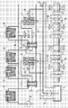
- Embodiments of the invention will now be described, by way of example only, with particular reference to the accompanying drawing, the sole figure of which shows schematically an embodiment of a fuel feeding system according to the invention.
- In the drawing reference numeral 1 indicates a fuel tank from which fuel is pumped by means of a low pressure pump 2 along a fuel line 3 into
high pressure pumps 4. The fuel line 3 is under relatively low constant pressure, for instance about 7 bar. The fuel line is provided with a constant pressure valve 5, through which the line 3 can be reconnected to the fuel tank 1. Instead of the constant pressure valve 5, a simpler throttle member may be used to maintain the low constant pressure. - The
high pressure pumps 4 are provided with control valves 6 and piston members 7. The piston members receive theirguidance 10 from cam members 8 of acam shaft 9 of the engine. When necessary, each cam member 8 may include several cams, whereby when a high pressure pump provides a certain volume flow per unit time into a pressure accumulator unit the outer dimensions of the pump may respectively be kept smaller so that the pressure shocks provided by it are correspondingly smaller. - Each
high pressure pump 4 is connected by means of ahigh pressure line 11 to a separatepressure accumulator unit 12. Eachaccumulator unit 12 is connected by means of pipes orducts 14 to electronically controlledinjectors 15 installed for two cylinders of the engine. - The
pressure accumulator units 12 are connected to each other by means of apipe 13. The purpose of thepipe 13 is to decrease possible pressure differences between the accumulator units. In practice the pressure prevailing in thehigh pressure line 11 and in thepressure accumulator units 12 is about 1200 bar but, if required, it may be varied preferably within the range of from 1000 to 1400 bar. Temporarily the pressure may even rise up to at least 1600 bar. When desired the operation of thehigh pressure pumps 4 and the injection pressures to be used can be controlled in accordance with engine load, operating speed or other parameters in a way known per se. - One
pressure accumulator unit 12 in the system is provided with anauxiliary valve 16, the operation of which is controlled by aprecontrol valve 17 attached to a servo oil circuit of the engine. Aservo oil pump 18 maintains a pressure of about 100 bar and the servo oil circuit is also made use of in a way known as such for theinjectors 15 to control the injection of fuel together with a conventional solenoid valve (not shown). By means of thevalve 16 thepressure accumulator units 12 of the system may be connected through aline 19 to the fuel tank 1. Thus, when necessary, by means of thevalve 16 thepressure accumulator units 12 may be de-pressurized. In addition thevalve 16 makes it possible to circulate fuel for instance for the purpose of heating it before starting of the engine. When desired, by opening and closing the control valves 6 in turn, it is also possible to ensure by means of thevalve 16 that the fuel flow takes place through all thepressure accumulator units 12. Further thevalve 16 may with advantage serve as a constant pressure valve since, in any event, the high pressure circuit also needs a constant pressure valve. - In the embodiment shown the volume of the pressure space of the
pressure accumulator units 12 may with advantage be about 0.7 litre and the diameter of thepipe 13 connecting theaccumulator units 12 together may be about 4.7 mm. These dimensions are most suitable for the case in which the injection into each cylinder is about 4700 mm<3> at full effect and full load of the engine, and they are prone for their part to eliminate possible pressure pulses between the accumulator units. - For clarity, the figure shows only two
pressure accumulator units 12 which feed fuel to injectors installed to four cylinders of the engine. The system according to the invention may naturally be applied to engines with several cylinders independent on the number of cylinders in each case. Similarly, when desired, one pressure accumulator unit may also feed fuel for, for example, three cylinders. - This should naturally be taken account of when dimensioning the system.
- The invention is not restricted to the embodiment shown, but several modifications are feasible within the scope of the attached claims.
Claims (11)
- A fuel feeding system for an engine with several cylinders, especially a large diesel engine, in which the fuel is fed from a fuel tank (1) to pressure supply means by means of high pressure pump means (4) and from the pressure supply means to the cylinders of the engine by means of injectors (15), whereby the pressure supply means includes at least two separate pressure accumulator units (12), each of which is connected to at least two injectors (15), characterized in that the pressure accumulator units (12) have pressure spaces continuously in connection with each other and in that one of the pressure accumulator units (12) is provided with a valve (16) for connecting the pressure spaces of the pressure accumulator units to the fuel tank (1).
- A fuel feeding system according to claim 1, characterized in that it includes a low pressure pump (2) for feeding fuel from the fuel tank (1), through the high pressure pumps (4) and into the pressure accumulator units (12).
- A fuel feeding system according to claim 2, characterized in that a feed circuit (3) of the low pressure pump (2) is provided with throttle means, a constant pressure valve or the like (5) for maintaining a uniform feeding pressure.
- A fuel feeding system according to claim 2 or 3, characterized in that the pressure in the feeding circuit (3) of the low pressure pump (2) is from 5 to 10 bar.
- A fuel feeding system according to any one of the preceding claims, characterized in that each high pressure pump (4) is provided with a control valve (6), by means of which the volume flow provided by the high pressure pump (4) is defined and by means of which the connection between the high pressure pump (4) and the low pressure pump (2) can additionally be closed.
- A fuel feeding system according to any one of the preceding claims, characterized in that said valve (16) of said one pressure accumulator unit (12) also serves as a constant pressure valve.
- A fuel feeding system according to any one of the preceding claims, characterized in that the fuel pressure in the pressure accumulator unit (12) is from about 800 to 1600 bar, preferably from 1000 to 1400 bar.
- A fuel feeding system according to any one of the preceding claims, characterized in that when each pressure accumulator unit (12) is connected to at least two injectors the volume of its pressure space is defined on the basis of the formula:
 Vtot = the common volume of all the pressure accumulator units (12);Vinj = the amount (volume) of fuel injected by one injector for one combustion occurrence of a cylinder, under full (100%) engine load; andNcyl = the number of cylinders in the engine;so that the value of S is in the range of from 50 to 100.
 - A fuel feeding system according to any one of the preceding claims, characterized in that the pressure accumulator units (12) are connected to each other by means of a pipe (13) or a duct connected from one unit to another and the diameter of which is from 4.5 to 5.0 mm, preferably about 4.7 mm.
- A fuel feeding system according to any one of the preceding claims, characterized in that the high pressure pump (4) receives its guidance from one or more cams (8) of a cam shaft (9) of the engine.
- An engine comprising several cylinders and having a fuel feeding system as claimed in any one of the preceding claims.
Applications Claiming Priority (2)
| Application Number | Priority Date | Filing Date | Title |
|---|---|---|---|
| FI981126A FI107831B (en) | 1998-05-20 | 1998-05-20 | Fuel Supply System |
| EP99303884A EP0959245B1 (en) | 1998-05-20 | 1999-05-19 | Fuel feeding system |
Related Parent Applications (2)
| Application Number | Title | Priority Date | Filing Date |
|---|---|---|---|
| EP99303884.3 Division | 1999-05-19 | ||
| EP99303884A Division EP0959245B1 (en) | 1998-05-20 | 1999-05-19 | Fuel feeding system |
Publications (3)
| Publication Number | Publication Date |
|---|---|
| EP1643119A2 true EP1643119A2 (en) | 2006-04-05 |
| EP1643119A3 EP1643119A3 (en) | 2009-02-18 |
| EP1643119B1 EP1643119B1 (en) | 2010-04-14 |
Family
ID=8551771
Family Applications (2)
| Application Number | Title | Priority Date | Filing Date |
|---|---|---|---|
| EP99303884A Expired - Lifetime EP0959245B1 (en) | 1998-05-20 | 1999-05-19 | Fuel feeding system |
| EP05109570A Expired - Lifetime EP1643119B1 (en) | 1998-05-20 | 1999-05-19 | Fuel feeding system |
Family Applications Before (1)
| Application Number | Title | Priority Date | Filing Date |
|---|---|---|---|
| EP99303884A Expired - Lifetime EP0959245B1 (en) | 1998-05-20 | 1999-05-19 | Fuel feeding system |
Country Status (6)
| Country | Link |
|---|---|
| US (1) | US6240901B1 (en) |
| EP (2) | EP0959245B1 (en) |
| JP (2) | JP4547052B2 (en) |
| AT (2) | ATE464472T1 (en) |
| DE (2) | DE69940234D1 (en) |
| FI (1) | FI107831B (en) |
Families Citing this family (25)
| Publication number | Priority date | Publication date | Assignee | Title |
|---|---|---|---|---|
| DE10010945B4 (en) * | 2000-03-06 | 2004-07-22 | Robert Bosch Gmbh | Pump for supplying a fuel injection system and a hydraulic valve control for internal combustion engines |
| FI113684B (en) * | 2001-04-10 | 2004-05-31 | Waertsilae Finland Oy | Fuel injection valve and fuel injection procedure |
| JP3849928B2 (en) * | 2001-09-03 | 2006-11-22 | 株式会社デンソー | Fuel injection pump |
| DE10157135B4 (en) * | 2001-11-21 | 2004-03-11 | Man B & W Diesel Ag | Fuel supply system in the form of a common rail system of an internal combustion engine with several cylinders |
| DE60325911D1 (en) | 2002-07-01 | 2009-03-05 | Mitsubishi Heavy Ind Ltd | Fuel injector and diesel engine with it |
| FI117349B (en) † | 2002-08-02 | 2006-09-15 | Waertsilae Finland Oy | Fuel supply system |
| FI117350B (en) * | 2002-10-16 | 2006-09-15 | Waertsilae Finland Oy | Device and method of fuel feed system |
| GB0303603D0 (en) * | 2003-02-17 | 2003-03-19 | Delphi Tech Inc | Improvements in or relating to pressurisation pumps |
| FI115008B (en) | 2003-05-13 | 2005-02-15 | Waertsilae Finland Oy | Procedure for monitoring the function of a solenoid |
| EP1489293B1 (en) * | 2003-06-20 | 2008-03-26 | Delphi Technologies, Inc. | Fuel system |
| DE10342387B3 (en) * | 2003-09-13 | 2005-05-25 | Man B & W Diesel Ag | Change-over system for change over of injection engine, has high pressure pump with common rail arrangement, and parallel longitudinal support arranged for cylinder-series, in which high pressure accumulator of arrangement is attached |
| JP4225240B2 (en) * | 2004-04-28 | 2009-02-18 | トヨタ自動車株式会社 | Fuel supply device for internal combustion engine |
| EP1612401B1 (en) * | 2004-06-30 | 2008-11-05 | C.R.F. Società Consortile per Azioni | An injection system for an internal combustion engine |
| ATE397723T1 (en) * | 2004-06-30 | 2008-06-15 | Fiat Ricerche | INJECTION SYSTEM FOR COMBUSTION ENGINE |
| KR100795406B1 (en) * | 2004-07-12 | 2008-01-17 | 얀마 가부시키가이샤 | Internal combustion engine with accumulator fuel injection device and accumulator fuel injection device |
| DE102004060003A1 (en) * | 2004-12-14 | 2006-07-06 | Man B & W Diesel Ag | Common rail fuel supply for multicylinder engine has at least two high-pressure pumps connected via separate pump line to one of supply lines |
| FR2892469B1 (en) * | 2005-10-24 | 2013-08-16 | Renault Sas | HIGH PRESSURE FUEL INJECTION DEVICE IN CYLINDERS OF AN INTERNAL COMBUSTION ENGINE |
| JP4121531B2 (en) | 2006-05-12 | 2008-07-23 | エムエーエヌ・ディーゼル・エーエス | Fuel circulation common rail fuel injection system for large two-cycle diesel engines |
| DE102006046214B3 (en) * | 2006-09-29 | 2008-04-30 | Siemens Ag | Fluid collection device |
| FI120844B (en) | 2007-05-31 | 2010-03-31 | Waertsilae Finland Oy | Fuel supply system fuel storage |
| FI122557B (en) * | 2009-04-02 | 2012-03-30 | Waertsilae Finland Oy | Fuel injection arrangement for a piston engine |
| FI20115126L (en) | 2011-02-09 | 2012-08-10 | Waertsilae Finland Oy | FUEL INJECTION SYSTEM |
| DE102011005096A1 (en) * | 2011-03-04 | 2012-09-06 | Man Diesel & Turbo Se | internal combustion engine |
| DE102016204408A1 (en) * | 2016-03-17 | 2017-09-21 | Robert Bosch Gmbh | Method for determining a setpoint for a manipulated variable for controlling a low-pressure pump |
| FI4030049T3 (en) | 2021-01-14 | 2025-03-14 | Waertsilae Finland Oy | A common rail fuel injection system for a multicylinder internal combustion piston engine, method of upgrading a fuel injection system in a multicylinder internal combustion piston engine and an internal combustion piston engine |
Family Cites Families (19)
| Publication number | Priority date | Publication date | Assignee | Title |
|---|---|---|---|---|
| US3827409A (en) * | 1972-06-29 | 1974-08-06 | Physics Int Co | Fuel injection system for internal combustion engines |
| JPS5359132A (en) * | 1976-11-09 | 1978-05-27 | Kubota Ltd | Over-head valve v-shaped diesel engine |
| AT364965B (en) * | 1978-12-19 | 1981-11-25 | Steyr Daimler Puch Ag | CAMSHAFT FOR INJECTION INTERNAL COMBUSTION ENGINES |
| JPS6018812B2 (en) * | 1980-02-05 | 1985-05-13 | ヤンマーディーゼル株式会社 | OHV diesel engine |
| JPH0759919B2 (en) * | 1986-04-04 | 1995-06-28 | 日本電装株式会社 | Fuel injection controller for diesel engine |
| JPH0413407Y2 (en) * | 1986-06-05 | 1992-03-27 | ||
| CH674243A5 (en) * | 1987-07-08 | 1990-05-15 | Dereco Dieselmotoren Forschung | |
| JPH0466742A (en) * | 1990-07-05 | 1992-03-03 | Yamaha Motor Co Ltd | Idling control device of high-pressure fuel injection type engine |
| US5230613A (en) | 1990-07-16 | 1993-07-27 | Diesel Technology Company | Common rail fuel injection system |
| JPH04308354A (en) * | 1991-04-05 | 1992-10-30 | Kubota Corp | Intake-exhaust valve and fuel injection pump drive unit for multiple cylinder diesel engine |
| JPH05240122A (en) * | 1992-02-29 | 1993-09-17 | Suzuki Motor Corp | Fuel piping structure for V-type engine |
| JP3303449B2 (en) * | 1993-08-09 | 2002-07-22 | 株式会社デンソー | Accumulation type fuel injection device |
| DE4335171C1 (en) * | 1993-10-15 | 1995-05-04 | Daimler Benz Ag | Fuel injection system for a multi-cylinder diesel internal combustion engine |
| DE19539885A1 (en) * | 1995-05-26 | 1996-11-28 | Bosch Gmbh Robert | Fuel supply system for IC engine |
| JPH08338339A (en) * | 1995-06-15 | 1996-12-24 | Isuzu Motors Ltd | diesel engine |
| JP3292017B2 (en) * | 1996-01-16 | 2002-06-17 | トヨタ自動車株式会社 | Fuel supply system for V-type engine |
| JPH1018936A (en) * | 1996-07-02 | 1998-01-20 | Sanshin Ind Co Ltd | Fuel piping structure of outboard motor |
| DE19626537C1 (en) * | 1996-07-02 | 1997-09-18 | Daimler Benz Ag | Fuel pressure regulating device for fuel injection equipment of internal combustion engine with high pressure pump |
| JPH10103175A (en) * | 1996-09-25 | 1998-04-21 | Zexel Corp | Fuel injection device |
-
1998
- 1998-05-20 FI FI981126A patent/FI107831B/en active
-
1999
- 1999-05-19 AT AT05109570T patent/ATE464472T1/en not_active IP Right Cessation
- 1999-05-19 AT AT99303884T patent/ATE420284T1/en active
- 1999-05-19 US US09/314,640 patent/US6240901B1/en not_active Expired - Lifetime
- 1999-05-19 DE DE69940234T patent/DE69940234D1/en not_active Expired - Lifetime
- 1999-05-19 EP EP99303884A patent/EP0959245B1/en not_active Expired - Lifetime
- 1999-05-19 EP EP05109570A patent/EP1643119B1/en not_active Expired - Lifetime
- 1999-05-19 DE DE69942256T patent/DE69942256D1/en not_active Expired - Lifetime
- 1999-05-20 JP JP14065899A patent/JP4547052B2/en not_active Expired - Lifetime
-
2010
- 2010-02-23 JP JP2010036958A patent/JP2010156345A/en active Pending
Also Published As
| Publication number | Publication date |
|---|---|
| EP1643119A3 (en) | 2009-02-18 |
| EP1643119B1 (en) | 2010-04-14 |
| ATE464472T1 (en) | 2010-04-15 |
| ATE420284T1 (en) | 2009-01-15 |
| FI981126A7 (en) | 1999-11-21 |
| JP2000027739A (en) | 2000-01-25 |
| JP2010156345A (en) | 2010-07-15 |
| FI107831B (en) | 2001-10-15 |
| EP0959245A2 (en) | 1999-11-24 |
| JP4547052B2 (en) | 2010-09-22 |
| DE69940234D1 (en) | 2009-02-26 |
| EP0959245B1 (en) | 2009-01-07 |
| EP0959245A3 (en) | 2001-01-10 |
| FI981126A0 (en) | 1998-05-20 |
| US6240901B1 (en) | 2001-06-05 |
| DE69942256D1 (en) | 2010-05-27 |
Similar Documents
| Publication | Publication Date | Title |
|---|---|---|
| EP0959245B1 (en) | Fuel feeding system | |
| US5392749A (en) | Hydraulically-actuated fuel injector system having separate internal actuating fluid and fuel passages | |
| US6776140B2 (en) | Fuel supply installation in the form of a common-rail system of an internal combustion engine having a plurality of cylinders | |
| EP1153215B1 (en) | Variable output pump for gasoline direct injection | |
| US6253735B1 (en) | Fuel feeding device | |
| US5577892A (en) | Method of injecting fuel including delayed magnetic spill valve actuation | |
| EP1288490B1 (en) | Control and safety valve arrangement in a fuel feeding system | |
| US5839412A (en) | Method for electronic fuel injector operation | |
| US6000380A (en) | Fuel injection for a multicylinder internal combustion engine | |
| US6497216B2 (en) | Pump for supplying a fuel injection system and for supplying a hydraulic valve controller for internal combustion engines | |
| KR100795406B1 (en) | Internal combustion engine with accumulator fuel injection device and accumulator fuel injection device | |
| US7270114B2 (en) | Fuel injection system for internal combustion engines | |
| JP2002508047A (en) | Direct fuel injection pump for spark ignition engine and injection system having the same | |
| US6223734B1 (en) | Fuel injection system for an internal combustion engine | |
| US6446603B1 (en) | Fuel injection system for internal combustion engines, and method for injecting fuel into the combustion chamber of an internal combustion engine | |
| EP1865193B1 (en) | Fuel injection system for an internal combustion engine | |
| US4951626A (en) | Electrically controlled fuel injection pump | |
| US20040118381A1 (en) | Accumulator fuel system | |
| RU2730540C1 (en) | Diesel fuel supply system | |
| EP3032086A1 (en) | Fuel injection arrangement | |
| US7406936B2 (en) | Accumulator fuel system | |
| EP3032091B1 (en) | Fuel injection arrangement | |
| US20070272215A1 (en) | Fuel Injection Sytem for Internal Combustion Engines | |
| EP3099924B1 (en) | Common rail fuel injection system | |
| EP3262294B1 (en) | Fuel injection system |
Legal Events
| Date | Code | Title | Description |
|---|---|---|---|
| PUAI | Public reference made under article 153(3) epc to a published international application that has entered the european phase |
Free format text: ORIGINAL CODE: 0009012 |
|
| AC | Divisional application: reference to earlier application |
Ref document number: 0959245 Country of ref document: EP Kind code of ref document: P |
|
| AK | Designated contracting states |
Kind code of ref document: A2 Designated state(s): AT BE CH CY DE DK ES FI FR GB GR IE IT LI LU MC NL PT SE |
|
| PUAL | Search report despatched |
Free format text: ORIGINAL CODE: 0009013 |
|
| AK | Designated contracting states |
Kind code of ref document: A3 Designated state(s): AT BE CH CY DE DK ES FI FR GB GR IE IT LI LU MC NL PT SE |
|
| 17P | Request for examination filed |
Effective date: 20090805 |
|
| AKX | Designation fees paid |
Designated state(s): AT BE CH CY DE DK ES FI FR GB GR IE IT LI LU MC NL PT SE |
|
| GRAP | Despatch of communication of intention to grant a patent |
Free format text: ORIGINAL CODE: EPIDOSNIGR1 |
|
| GRAS | Grant fee paid |
Free format text: ORIGINAL CODE: EPIDOSNIGR3 |
|
| GRAA | (expected) grant |
Free format text: ORIGINAL CODE: 0009210 |
|
| AC | Divisional application: reference to earlier application |
Ref document number: 0959245 Country of ref document: EP Kind code of ref document: P |
|
| AK | Designated contracting states |
Kind code of ref document: B1 Designated state(s): AT BE CH CY DE DK ES FI FR GB GR IE IT LI LU MC NL PT SE |
|
| REG | Reference to a national code |
Ref country code: GB Ref legal event code: FG4D |
|
| REG | Reference to a national code |
Ref country code: CH Ref legal event code: EP |
|
| REG | Reference to a national code |
Ref country code: IE Ref legal event code: FG4D |
|
| REF | Corresponds to: |
Ref document number: 69942256 Country of ref document: DE Date of ref document: 20100527 Kind code of ref document: P |
|
| REG | Reference to a national code |
Ref country code: NL Ref legal event code: VDEP Effective date: 20100414 |
|
| PG25 | Lapsed in a contracting state [announced via postgrant information from national office to epo] |
Ref country code: SE Free format text: LAPSE BECAUSE OF FAILURE TO SUBMIT A TRANSLATION OF THE DESCRIPTION OR TO PAY THE FEE WITHIN THE PRESCRIBED TIME-LIMIT Effective date: 20100414 Ref country code: NL Free format text: LAPSE BECAUSE OF FAILURE TO SUBMIT A TRANSLATION OF THE DESCRIPTION OR TO PAY THE FEE WITHIN THE PRESCRIBED TIME-LIMIT Effective date: 20100414 Ref country code: ES Free format text: LAPSE BECAUSE OF FAILURE TO SUBMIT A TRANSLATION OF THE DESCRIPTION OR TO PAY THE FEE WITHIN THE PRESCRIBED TIME-LIMIT Effective date: 20100725 |
|
| PG25 | Lapsed in a contracting state [announced via postgrant information from national office to epo] |
Ref country code: AT Free format text: LAPSE BECAUSE OF FAILURE TO SUBMIT A TRANSLATION OF THE DESCRIPTION OR TO PAY THE FEE WITHIN THE PRESCRIBED TIME-LIMIT Effective date: 20100414 Ref country code: FI Free format text: LAPSE BECAUSE OF FAILURE TO SUBMIT A TRANSLATION OF THE DESCRIPTION OR TO PAY THE FEE WITHIN THE PRESCRIBED TIME-LIMIT Effective date: 20100414 |
|
| PG25 | Lapsed in a contracting state [announced via postgrant information from national office to epo] |
Ref country code: MC Free format text: LAPSE BECAUSE OF NON-PAYMENT OF DUE FEES Effective date: 20100531 Ref country code: CY Free format text: LAPSE BECAUSE OF FAILURE TO SUBMIT A TRANSLATION OF THE DESCRIPTION OR TO PAY THE FEE WITHIN THE PRESCRIBED TIME-LIMIT Effective date: 20100428 Ref country code: GR Free format text: LAPSE BECAUSE OF FAILURE TO SUBMIT A TRANSLATION OF THE DESCRIPTION OR TO PAY THE FEE WITHIN THE PRESCRIBED TIME-LIMIT Effective date: 20100715 |
|
| PG25 | Lapsed in a contracting state [announced via postgrant information from national office to epo] |
Ref country code: DK Free format text: LAPSE BECAUSE OF FAILURE TO SUBMIT A TRANSLATION OF THE DESCRIPTION OR TO PAY THE FEE WITHIN THE PRESCRIBED TIME-LIMIT Effective date: 20100414 Ref country code: PT Free format text: LAPSE BECAUSE OF FAILURE TO SUBMIT A TRANSLATION OF THE DESCRIPTION OR TO PAY THE FEE WITHIN THE PRESCRIBED TIME-LIMIT Effective date: 20100816 |
|
| PLBE | No opposition filed within time limit |
Free format text: ORIGINAL CODE: 0009261 |
|
| REG | Reference to a national code |
Ref country code: FR Ref legal event code: ST Effective date: 20110131 |
|
| STAA | Information on the status of an ep patent application or granted ep patent |
Free format text: STATUS: NO OPPOSITION FILED WITHIN TIME LIMIT |
|
| PG25 | Lapsed in a contracting state [announced via postgrant information from national office to epo] |
Ref country code: BE Free format text: LAPSE BECAUSE OF FAILURE TO SUBMIT A TRANSLATION OF THE DESCRIPTION OR TO PAY THE FEE WITHIN THE PRESCRIBED TIME-LIMIT Effective date: 20100414 |
|
| 26N | No opposition filed |
Effective date: 20110117 |
|
| PG25 | Lapsed in a contracting state [announced via postgrant information from national office to epo] |
Ref country code: IE Free format text: LAPSE BECAUSE OF NON-PAYMENT OF DUE FEES Effective date: 20100519 |
|
| PG25 | Lapsed in a contracting state [announced via postgrant information from national office to epo] |
Ref country code: FR Free format text: LAPSE BECAUSE OF NON-PAYMENT OF DUE FEES Effective date: 20100614 |
|
| PG25 | Lapsed in a contracting state [announced via postgrant information from national office to epo] |
Ref country code: LU Free format text: LAPSE BECAUSE OF NON-PAYMENT OF DUE FEES Effective date: 20100519 |
|
| PGFP | Annual fee paid to national office [announced via postgrant information from national office to epo] |
Ref country code: DE Payment date: 20180518 Year of fee payment: 20 Ref country code: CH Payment date: 20180521 Year of fee payment: 20 |
|
| PGFP | Annual fee paid to national office [announced via postgrant information from national office to epo] |
Ref country code: IT Payment date: 20180522 Year of fee payment: 20 |
|
| PGFP | Annual fee paid to national office [announced via postgrant information from national office to epo] |
Ref country code: GB Payment date: 20180515 Year of fee payment: 20 |
|
| REG | Reference to a national code |
Ref country code: DE Ref legal event code: R071 Ref document number: 69942256 Country of ref document: DE |
|
| REG | Reference to a national code |
Ref country code: CH Ref legal event code: PL |
|
| REG | Reference to a national code |
Ref country code: GB Ref legal event code: PE20 Expiry date: 20190518 |
|
| PG25 | Lapsed in a contracting state [announced via postgrant information from national office to epo] |
Ref country code: GB Free format text: LAPSE BECAUSE OF EXPIRATION OF PROTECTION Effective date: 20190518 |