EP1642648A1 - Apparatus and method for regulating the temperature of a liquid - Google Patents
Apparatus and method for regulating the temperature of a liquid Download PDFInfo
- Publication number
- EP1642648A1 EP1642648A1 EP05017580A EP05017580A EP1642648A1 EP 1642648 A1 EP1642648 A1 EP 1642648A1 EP 05017580 A EP05017580 A EP 05017580A EP 05017580 A EP05017580 A EP 05017580A EP 1642648 A1 EP1642648 A1 EP 1642648A1
- Authority
- EP
- European Patent Office
- Prior art keywords
- temperature
- control unit
- liquid
- sample vessels
- sample
- Prior art date
- Legal status (The legal status is an assumption and is not a legal conclusion. Google has not performed a legal analysis and makes no representation as to the accuracy of the status listed.)
- Withdrawn
Links
- 239000007788 liquid Substances 0.000 title claims abstract description 42
- 238000000034 method Methods 0.000 title claims abstract description 13
- 230000001105 regulatory effect Effects 0.000 title description 2
- 238000010521 absorption reaction Methods 0.000 claims abstract description 26
- 230000005855 radiation Effects 0.000 claims abstract description 13
- 239000000463 material Substances 0.000 claims abstract description 8
- 238000005496 tempering Methods 0.000 claims description 17
- UQSXHKLRYXJYBZ-UHFFFAOYSA-N Iron oxide Chemical compound [Fe]=O UQSXHKLRYXJYBZ-UHFFFAOYSA-N 0.000 claims description 4
- 239000011521 glass Substances 0.000 claims description 3
- 229920000049 Carbon (fiber) Polymers 0.000 claims description 2
- 229910052782 aluminium Inorganic materials 0.000 claims description 2
- 239000004917 carbon fiber Substances 0.000 claims description 2
- 239000000919 ceramic Substances 0.000 claims description 2
- 230000005484 gravity Effects 0.000 claims description 2
- 239000000049 pigment Substances 0.000 claims description 2
- 238000010438 heat treatment Methods 0.000 abstract description 5
- 239000011324 bead Substances 0.000 abstract description 2
- 239000002245 particle Substances 0.000 description 4
- 230000000694 effects Effects 0.000 description 3
- 229910052736 halogen Inorganic materials 0.000 description 3
- 150000002367 halogens Chemical class 0.000 description 3
- 150000007523 nucleic acids Chemical class 0.000 description 3
- 102000039446 nucleic acids Human genes 0.000 description 3
- 108020004707 nucleic acids Proteins 0.000 description 3
- 230000008569 process Effects 0.000 description 3
- 239000000126 substance Substances 0.000 description 3
- 239000004743 Polypropylene Substances 0.000 description 2
- 238000009529 body temperature measurement Methods 0.000 description 2
- 238000005516 engineering process Methods 0.000 description 2
- 239000010408 film Substances 0.000 description 2
- 239000012530 fluid Substances 0.000 description 2
- 238000005259 measurement Methods 0.000 description 2
- 229920000642 polymer Polymers 0.000 description 2
- 239000007787 solid Substances 0.000 description 2
- 239000010409 thin film Substances 0.000 description 2
- XLYOFNOQVPJJNP-UHFFFAOYSA-N water Substances O XLYOFNOQVPJJNP-UHFFFAOYSA-N 0.000 description 2
- 240000007817 Olea europaea Species 0.000 description 1
- 230000002745 absorbent Effects 0.000 description 1
- 239000002250 absorbent Substances 0.000 description 1
- 238000000862 absorption spectrum Methods 0.000 description 1
- XAGFODPZIPBFFR-UHFFFAOYSA-N aluminium Chemical compound [Al] XAGFODPZIPBFFR-UHFFFAOYSA-N 0.000 description 1
- 230000015572 biosynthetic process Effects 0.000 description 1
- 210000001124 body fluid Anatomy 0.000 description 1
- 239000010839 body fluid Substances 0.000 description 1
- 239000012876 carrier material Substances 0.000 description 1
- 230000008859 change Effects 0.000 description 1
- 238000004140 cleaning Methods 0.000 description 1
- 229920001577 copolymer Polymers 0.000 description 1
- 230000001419 dependent effect Effects 0.000 description 1
- 238000009792 diffusion process Methods 0.000 description 1
- 230000006872 improvement Effects 0.000 description 1
- 238000004519 manufacturing process Methods 0.000 description 1
- 230000004048 modification Effects 0.000 description 1
- 238000012986 modification Methods 0.000 description 1
- 238000005457 optimization Methods 0.000 description 1
- -1 polypropylene Polymers 0.000 description 1
- 229920001155 polypropylene Polymers 0.000 description 1
- 239000011541 reaction mixture Substances 0.000 description 1
- 238000001228 spectrum Methods 0.000 description 1
- 239000012798 spherical particle Substances 0.000 description 1
- 238000000411 transmission spectrum Methods 0.000 description 1
Images


Classifications
-
- B—PERFORMING OPERATIONS; TRANSPORTING
- B01—PHYSICAL OR CHEMICAL PROCESSES OR APPARATUS IN GENERAL
- B01L—CHEMICAL OR PHYSICAL LABORATORY APPARATUS FOR GENERAL USE
- B01L7/00—Heating or cooling apparatus; Heat insulating devices
-
- B—PERFORMING OPERATIONS; TRANSPORTING
- B01—PHYSICAL OR CHEMICAL PROCESSES OR APPARATUS IN GENERAL
- B01L—CHEMICAL OR PHYSICAL LABORATORY APPARATUS FOR GENERAL USE
- B01L2300/00—Additional constructional details
- B01L2300/18—Means for temperature control
- B01L2300/1861—Means for temperature control using radiation
- B01L2300/1872—Infrared light
-
- B—PERFORMING OPERATIONS; TRANSPORTING
- B01—PHYSICAL OR CHEMICAL PROCESSES OR APPARATUS IN GENERAL
- B01L—CHEMICAL OR PHYSICAL LABORATORY APPARATUS FOR GENERAL USE
- B01L3/00—Containers or dishes for laboratory use, e.g. laboratory glassware; Droppers
- B01L3/50—Containers for the purpose of retaining a material to be analysed, e.g. test tubes
- B01L3/508—Containers for the purpose of retaining a material to be analysed, e.g. test tubes rigid containers not provided for above
- B01L3/5085—Containers for the purpose of retaining a material to be analysed, e.g. test tubes rigid containers not provided for above for multiple samples, e.g. microtitration plates
- B01L3/50851—Containers for the purpose of retaining a material to be analysed, e.g. test tubes rigid containers not provided for above for multiple samples, e.g. microtitration plates specially adapted for heating or cooling samples
Definitions
- the present invention relates to a device for adjusting a temperature of a liquid according to the preamble of claim 1 and a corresponding method.
- the present invention is therefore based on the object of specifying a device for adjusting a temperature of a liquid, wherein the device does not have one or more of the disadvantages mentioned above.
- the invention has the following advantages: Since the liquid to be examined contains absorption elements which have a thermal conductivity greater than 0.6 W / m K, the temperature setting in the liquid to be examined is considerably accelerated. Thus, the throughput of samples per unit time can be increased accordingly.
- Fig. 1 shows a schematic representation of an embodiment of the invention, in which eight sample vessels 11 to 18 are arranged substantially on a straight line, wherein a transport unit 20 is provided to hold one hand, the sample vessels 11 to 18 in position and on the other hand, to a to ensure easy transport of the sample vessels 11 to 18.
- a temperature control unit 2 is provided laterally along the sample vessels 11 to 18 or the transport unit 20, by means of which the temperature of the liquid present in the sample vessels 11 to 18 can be adjusted.
- a control unit 1 is provided, which is operatively connected to the temperature control unit 2, ie in the control unit 1, a control signal is generated, which leads to a corresponding temperature radiation through the temperature control unit 2.
- a first embodiment of the present invention is that the control unit 1 receives no feedback on the temperature generated in the sample vessels 11 to 18.
- a further embodiment of the present invention is that sensor elements 3 are provided in the region of the sample vessels 11 to 18, by means of which the respective temperature of the existing in the sample vessels 11 to 18 fluids can be determined.
- sensor elements 3 are provided in the region of the sample vessels 11 to 18, by means of which the respective temperature of the existing in the sample vessels 11 to 18 fluids can be determined.
- the possibility that for each sample vessel 11 to 18 a sensor element 3 is present on the other hand the possibility that the temperature is measured only in one of the sample vessels 11 to 18, in which case it is assumed that the measured temperature value in all other sample vessels 11 to 18 is the same.
- the embodiments of the present invention with sensor elements 3 enables the regulation of the temperature radiation of the temperature control unit 2, whereby a desired temperature of the liquids present in the sample vessels can be adjusted quickly and precisely.
- denoted by 5 is a system bus, via which the device according to the invention can be coupled, for example, to a higher-level system which, for example, assumes all the controls of a process
- the tempering unit 2 is particularly suitable for an IR (infrared) radiation unit.
- An IR radiation unit irradiates the liquid in the sample vessels 11 to 18 in the infrared wavelength range.
- other wavelength ranges are also conceivable.
- the tempering unit 2 used is realized, for example, as a surface radiator (two-dimensional) in thick-film or thin-film technology.
- the absorption elements have the task to absorb the radiation energy emitted by the temperature control unit 2 and deliver it as heat to the liquids contained in the sample vessels 11 to 18.
- the choice for an absorption element is therefore dependent on the temperature control unit 2 used or on the wavelength range of the radiation used.
- absorption elements are, for example, spherical particles in the size of 0.1 to 100 .mu.m, in particular from 0.5 to 5 microns. These are glass beads with enclosed magnetic pigments, for example iron oxide. Such absorption elements are also referred to as MGPs (Magnetic Glass Particles). Furthermore, the absorption can be increased by the use of polymers (PS) for the production of absorbent elements. Finally, can the thermal conductivity and thus a heat input into the liquids can be increased by adding absorption elements of other inert particles (for example of aluminum, ceramic or carbon fibers).
- PS Polymers
- Particularly suitable absorption elements are particulate solids, as described, for example, in the known teachings according to WO 96/41 811 or US Pat. No. 6,255,477 B1 or WO 00/32 762 or US Pat. No. 6,545,143 B1 or WO 01/37 291 or US Pat US 2003/224 366 A1 of the same Applicant have been described.
- the disclosure of the above-mentioned international patent applications is therefore fully an integral part of the present patent application.
- the absorption elements primarily have the task of converting radiation into heat and delivering it to the liquid to be heated in the sample vessel in order to be able to achieve a desired temperature of the liquid as quickly as possible.
- embodiments are conceivable and desirable in which particles are used as absorption elements, to which nucleic acid can be reversibly bound, as has also been described in the aforementioned international patent application with the publication number WO 96/41 811.
- the method consists of binding nucleic acids to the particles for cleaning. Through the connection, an extremely efficient heat transfer can be obtained.
- the liquid to be examined is included preferably aqueous, in particular a nucleic acid-containing sample, for example a body fluid or a fluid derived therefrom.
- sample vessels 11 to 18 are made of a material with low heat capacity and / or reduced absorption.
- COC cycloolefin copolymer
- PP polypropylene
- the measurement of the instantaneous temperature by means of the sensor elements 3 is preferably, but not necessarily, from above, that is on the Opening in the sample vessels 11 to 18. This can be a direct measurement the temperature can be made, and there are no Messvertigschept due to lying between the sensor element 3 and the liquid vessel walls to be expected.
- the liquid in the sample vessels 11 to 18 can be heated from below or from above. In this case, a temperature measurement from the side is preferred.
- FIG. 2 shows a further embodiment of the device according to the invention with a linear IR incubator.
- the embodiment according to FIG. 2 comprises a rake-shaped tempering unit, which consists of the essentially parallel tempering elements 2a to 2f.
- the tempering elements 2a to 2f can also be produced with the mentioned thin-film or thick-film technologies.
- the control unit 1 is individually connected to the temperature control 2a to 2f.
- the temperature measurement takes place, as in the embodiment according to FIG. 1, via sensor elements 3, which are connected to the control unit 1 (shown in dashed lines in FIG. 2).
- the sensor elements 3 arranged above or below the sample vessels 11 to 15.
- sensor elements 3 ' are provided directly on the temperature control elements 2a to 2f, as is indicated by way of example in the case of the first temperature control element 2a.
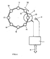
- Fig. 3 shows a further embodiment of the inventive device is shown.
- a so-called rotor-IR incubator is used, in which the sample vessels 11 to 1B are arranged on a circle. Accordingly, the sample vessels 11 to 18 are held in position by a circular transport unit 20.
- the tempering unit 2 is arranged in the center of the circular transport unit 20, so that the heat rays run radially, thus impinging laterally on the sample vessels 11 to 18.
- a single or multiple sensor elements 3 are also provided in that according to FIG. 3 in order to measure the temperature of the liquids contained in the sample vessels 11 to 18 and optionally to the control unit 1 for regulating the temperature to pass over the temperature control unit 2.
- the sensor unit or the sensor units are to be suitably placed.
- Embodiment with centrally arranged tempering 2 is particularly suitable an arrangement of the sensor unit 3 on the sample vessels 11 to 18, whereby a direct influence by the temperature control unit 2 is excluded.
- FIG. 4 shows a further embodiment of the device according to the invention with a rotor-IR-incubator.
- the embodiment according to FIG. 4 consists in that the temperature control unit 2 is arranged below one of the sample vessels 11 to 18. Conceivable and in a modification of the embodiment according to FIG. 4, a further embodiment variant is that a temperature control unit 2 is arranged under a plurality of or among all sample vessels 11 to 18.
- a water temperature of 80 ° Celsius was reached after about 40 seconds.
- the sample vessel is placed concentrically over a halogen lamp as a tempering unit, wherein the halogen lamp is arranged in a rotationally symmetrical mirror.
- a wavelength filter is further provided between the tempering unit and the sample vessel.
- a sensor element is non-contact Temperature sensor provided, with which the control unit and the temperature control unit are operatively connected.
- tempering unit 2 which generates beams in the infrared range, is particularly suitable for all of the described embodiments according to the invention. Nevertheless, tempering units are also conceivable which generate beams in other wavelength ranges. Decisive is a vote of the used rays in connection with the used materials for the absorption elements and for the sample vessels 11 to 18.
- Suitable sample vessels are conventional so-called tubes, which consist of a cylindrical section and leak towards the closed end, for example, in a tip.
- flat cells consist essentially of one or more chambers with a small depth (a few hundred microns) in a carrier material, wherein the outer dimensions of the chamber and its geometry may be arbitrary.
- Eppendorf tubes or other tubes with a capacity of, for example, 300 .mu.l to 2.5 ml are suitable.
- hollow cylinders and capillary tubes are also suitable as sample vessels.
- the capacity of the sample vessels may be up to about 5 ml, in particular in the range from 0.1 to 5 ml or in particular in the range from 0.3 to 2.5 ml.
- the capacity is selected in a range of 0.1 to 100 ul, preferably in the range between 0.3 and 50 ul, preferably in the range between 0.5 and 0.9 ul or in the range between 30 and 40 ul.
- the cells have an olive shape, i. the cross-sectional area of a cell is oval with a maximum width of 6 mm and a maximum length of 14 mm, the cell depth being about 0.65 mm.
- the cell corresponds to a cylindrical cavity, for example, has a diameter of 1.5 mm and a height of also 1.5 mm.
- the present invention is particularly suitable for the following applications: incubators, thermal cyclers and all applications related to energy input.
Abstract
Description
Die vorliegende Erfindung betrifft eine Vorrichtung zum Einstellen einer Temperatur einer Flüssigkeit nach dem Oberbegriff gemäss Anspruch 1 sowie ein entsprechendes Verfahren.The present invention relates to a device for adjusting a temperature of a liquid according to the preamble of
Es ist allgemein bekannt, dass chemische Analysen von Proben und chemische/physikalische Prozesse bei einer vorbestimmten Temperatur ausgeführt werden müssen, um korrekte Resultate erhalten zu können. Insbesondere bei einer grossen Anzahl von chemischen Analysen innerhalb eines relativ kurzen Zeitabschnittes oder bei Prozessen, bei denen eine Temperatur oder unterschiedliche Temperaturen eingestellt werden müssen, erfordern leistungsfähige und kostenaufwendige Temperiereinheiten, damit diese Anforderungen erfüllt werden können.It is well known that chemical analyzes of samples and chemical / physical processes must be carried out at a predetermined temperature in order to obtain correct results. In particular, in a large number of chemical analyzes within a relatively short period of time or in processes in which a temperature or different temperatures must be set, require powerful and costly temperature control units, so that these requirements can be met.
Es sind verschiedene Vorrichtungen und Verfahren zur Einstellung der Temperatur bekannt. Stellvertretend wird auf die folgenden Druckschriften verwiesen: DE-42 03 202 A1, EP-0 160 282 B1, EP-0 318 255 A2, WO 98/38487, US-6 210 882 und EP-0-345 882 A1.Various devices and methods for adjusting the temperature are known. By way of example, reference is made to the following publications: DE-42 03 202 A1, EP-0 160 282 B1, EP-0 318 255 A2, WO 98/38487, US Pat. No. 6,210,882 and EP-0-345 882 A1.
Die bekannten Lehren lassen sich grundsätzlich in zwei Gruppen einteilen. Zur ersten Gruppe gehören die so genannten Festkörperinkubatoren, bei denen die Proben durch den Festkörper geheizt oder gekühlt werden, was je nach Wärmekapazität entsprechend viel Zeit in Anspruch nimmt. Müssen flüssige Proben temperiert werden, ergeben sich eines oder mehrere der nachfolgenden Probleme:
- Grosse thermische Massen müssen bei einer Temperaturänderung mitgeheizt oder mitgekühlt werden;
- Es treten Diffusionslimitationen zwischen einer geheizten Probengefässwandung und der Flüssigkeit auf (Grenzschichtbildung);
- ein direkter Kontakt zwischen der Wärmequelle bzw. Wärmesenke und dem zu beheizenden Probengefäss ist erforderlich; eine schlechte Kontaktierung zwischen Temperiereinheit und Probengefäss führt zu einer erheblichen Verzögerung in der Temperatureinstellung;
- Kontaktierungen durch Sensorkabel wirken als Wärmesenken und führen zu zusätzlichen Verlusten.
- Large thermal masses must be co-heated or co-cooled with a change in temperature;
- Diffusion limitations occur between a heated sample vessel wall and the liquid (boundary layer formation);
- direct contact between the heat source or heat sink and the sample vessel to be heated is required; poor contact between tempering unit and sample vessel leads to a considerable delay in the temperature setting;
- Contacts through sensor cables act as heat sinks and lead to additional losses.
Zur zweiten Gruppe gehören Temperiereinheiten, die auf einer Bestrahlung, insbesondere einer IR-(Infrarot)-Bestrahlung, basieren. Zwar kann grundsätzlich ein gegenüber der ersten Gruppe verbessertes Verhalten festgestellt werden, doch ergeben sich auch bei dieser zweiten Gruppe eine Reihe von zu beachtenden Nachteilen, welche zu einem suboptimalen Aufheizverhalten bei Flüssigkeiten führen:
- nicht optimierte Absorptionsspektren der zu erwärmenden Reaktionsgemische;
- nicht optimierte Transmissionsspektren der Probengefässe;
- anderen Systemelemente werden ungewollt durch die IR-Strahlung erwärmt.
- non-optimized absorption spectra of the reaction mixtures to be heated;
- non-optimized transmission spectra of the sample vessels;
- other system elements are inadvertently heated by the IR radiation.
Der vorliegenden Erfindung liegt daher die Aufgabe zugrunde, eine Vorrichtung zum Einstellen einer Temperatur einer Flüssigkeit anzugeben, wobei die Vorrichtung einen oder mehrere der vorstehend genannten Nachteile nicht aufweist.The present invention is therefore based on the object of specifying a device for adjusting a temperature of a liquid, wherein the device does not have one or more of the disadvantages mentioned above.
Diese Aufgabe wird durch den im kennzeichnenden Teil des Patentanspruchs 1 angegebenen Massnahmen gelöst. vorteilhafte Ausgestaltungen der Erfindung sowie ein verfahren sind in weiteren Ansprüchen angegeben.This object is achieved by the measures indicated in the characterizing part of
Die Erfindung weist die folgenden Vorteile auf: Indem die zu untersuchende Flüssigkeit Absorptionselemente enthält, die eine Wärmeleitfähigkeit grösser als 0.6 W/m K aufweisen, wird die Temperatureinstellung in der zu untersuchenden Flüssigkeit erheblich beschleunigt. Damit kann der Durchsatz von Proben pro Zeiteinheit entsprechend gesteigert werden.The invention has the following advantages: Since the liquid to be examined contains absorption elements which have a thermal conductivity greater than 0.6 W / m K, the temperature setting in the liquid to be examined is considerably accelerated. Thus, the throughput of samples per unit time can be increased accordingly.
Die Erfindung wird nachfolgend anhand von Zeichnungen beispielsweise erläutert. Dabei zeigen
- Fig. 1,
- in schematischer Darstellung, eine erfindungsgemässe Vorrichtung als so genannter Linear-IR-Inkubator,
- Fig. 2,
- wiederum in schematischer Darstellung, eine weitere Ausführungsform einer erfindungsgemässen Vorrichtung als Linear-IR-Inkubator,
- Fig. 3,
- wiederum in schematischer Darstellung, eine weitere Ausführungsform der erfindungsgemässen Vorrichtung als so genannter Rotor-IR-Inkubator und
- Fig. 4,
- wiederum in schematischer Darstellung, eine noch weitere Ausführungsform der erfindungsgemässen Vorrichtung als Rotor-IR-Inkubator.
- Fig. 1,
- in a schematic representation, a device according to the invention as a so-called linear IR incubator,
- 2,
- again in a schematic representation, a further embodiment of a device according to the invention as a linear IR incubator,
- 3,
- in turn, in a schematic representation, another embodiment of the inventive device as a so-called rotor IR incubator and
- 4,
- in turn, in a schematic representation, a still further embodiment of the inventive device as a rotor-IR incubator.
Fig. 1 zeigt in schematischer Darstellung eine Ausführungsform der Erfindung, bei der acht Probengefässe 11 bis 18 im Wesentlichen auf einer Geraden angeordnet sind, wobei eine Transporteinheit 20 vorgesehen ist, um einerseits die Probengefässe 11 bis 18 in Position zu halten und anderseits, um einen einfachen Transport der Probengefässe 11 bis 18 zu gewährleisten. Seitlich entlang der Probengefässe 11 bis 18 bzw. der Transporteinheit 20 ist eine Temperiereinheit 2 vorgesehen, mit Hilfe der die Temperatur der in den Probengefässen 11 bis 18 vorhandenen Flüssigkeit eingestellt werden kann. Hierzu ist eine Steuereinheit 1 vorgesehen, die mit der Temperiereinheit 2 wirkverbunden ist, d.h. in der Steuereinheit 1 wird ein Steuersignal generiert, welches zu einer entsprechenden Temperaturstrahlung durch die Temperiereinheit 2 führt.Fig. 1 shows a schematic representation of an embodiment of the invention, in which eight
Grundsätzlich besteht eine erste Ausführungsform der vorliegenden Erfindung darin, dass die Steuereinheit 1 keine Rückmeldung über die in den Probengefässen 11 bis 18 erzeugten Temperatur erhält.Basically, a first embodiment of the present invention is that the
Eine weitere Ausführungsform der vorliegenden Erfindung besteht jedoch, wie in Fig. 1 gezeigt, darin, dass Sensorelemente 3 im Bereich der Probengefässe 11 bis 18 vorgesehen sind, mit Hilfe derer die jeweilige Temperatur der in den Probengefässen 11 bis 18 vorhandenen Flüssigkeiten bestimmt werden kann. Dabei besteht einerseits die Möglichkeit, dass für jedes Probengefäss 11 bis 18 ein Sensorelement 3 vorhanden ist, anderseits die Möglichkeit, dass die Temperatur lediglich in einem der Probengefässe 11 bis 18 gemessen wird, wobei dann angenommen wird, dass der gemessene Temperaturwert in allen anderen Probengefässen 11 bis 18 gleich ist.A further embodiment of the present invention, however, as shown in Fig. 1, is that
Die Ausführungsformen der vorliegenden Erfindung mit Sensorelementen 3 ermöglicht die Regulierung der Temperaturstrahlung der Temperiereinheit 2, womit eine gewünschte Temperatur der in den Probengefässen vorhandenen Flüssigkeiten rasch und präzise eingestellt werden kann.The embodiments of the present invention with
In der Fig. 1 ist mit 5 ein Systembus bezeichnet, über den die erfindungsgemässe Vorrichtung beispielsweise an ein übergeordnetes System gekoppelt werden kann, das beispielsweise alle Steuerungen eines Prozesses übernimmt-Es hat sich gezeigt, dass sich als Temperiereinheit 2 ein IR-(Infrarot)-Strahlungseinheit besonders eignet. Eine IR-Strahlungseinheit bestrahlt die Flüssigkeit in den Probengefässen 11 bis 18 im infraroten Wellenlängenbereich. Denkbar sind jedoch auch andere Wellenlängenbereiche.In FIG. 1, denoted by 5 is a system bus, via which the device according to the invention can be coupled, for example, to a higher-level system which, for example, assumes all the controls of a process It has been found that the
Die eingesetzte Temperiereinheit 2 ist beispielsweise als Flächenstrahler (zweidimensional) in Dickfilm- oder Dünnfilmtechnologie realisiert.The
Damit die Einstellung der Temperatur der in den Probengefässen 11 bis 18 enthaltenen Flüssigkeiten schneller und effizienter vorgenommen werden kann, wird erfindungsgemäss vorgeschlagen, den in den Probengefässen enthaltenen Flüssigkeiten Absorptionselemente beizumischen. Die Absorptionselemente haben dabei die Aufgabe, die von der Temperiereinheit 2 abgegebene Strahlungsenergie aufzunehmen und als Wärme an die in den Probengefässen 11 bis 18 enthaltenen Flüssigkeiten abzugeben. Die Wahl für ein Absorptionselement ist daher abhängig von der verwendeten Temperiereinheit 2 bzw. vom verwendeten Wellenlängenbereich der Strahlung.So that the adjustment of the temperature of the liquids contained in the
Die Absorptionselemente sollen die zu untersuchende oder zu verarbeitende Flüssigkeit chemisch nicht beeinflussen - d.h. in Bezug auf die Flüssigkeit inert sein - und zudem beispielsweise eine oder mehrere der folgenden Eigenschaften aufweisen:
- hohe Wärmeleitfähigkeit, vorzugsweise grösser als 0.6 w/m K;
- geringe Wärmekapazität, vorzugsweise kleiner als 4000 J/kg K;
- magnetisiert bzw. magnetisierbar;
- geringe spezifische Dichte, vorzugsweise kleiner als 6 g/cm3.
- high thermal conductivity, preferably greater than 0.6 w / m K;
- low heat capacity, preferably less than 4000 J / kg K;
- magnetized or magnetizable;
- low specific gravity, preferably less than 6 g / cm 3 .
Mit den erfindungsgemässen Absorptionselementen kann ein oder mehrere der nachfolgenden Effekte erzielt werden:
- Höherer Wirkungsgrad;
- Höhere Aufheizgeschwindigkeit der in
den Probengefässen 11bis 18 enthaltnen Flüssigkeiten; - Stärkere Konvektionseffekte innerhalb der Probengefässe 11
bis 18 aufgrund des lokalen Wärmeeintrages an den Absorptionselementen; - Bessere Homogenität innerhalb der zu erwärmenden Flüssigkeit infolge des verstärkten Konvektionseffektes innerhalb der Probengefässe 11 bis 18 (ein zusätzliches Mischen der Flüssigkeiten ist nicht notwendig).
- Higher efficiency;
- Higher heating rate of the liquids contained in
sample vessels 11 to 18; - Greater convection effects within the
sample vessels 11 to 18 due to the local heat input at the absorption elements; - Better homogeneity within the liquid to be heated due to the increased convection effect within the
sample vessels 11 to 18 (additional mixing of the liquids is not necessary).
Als Absorptionselemente eignen sich beispielsweise kugelförmige Partikel in der Grösse von 0.1 bis 100µm, insbesondere von 0.5 bis 5 µm. Es handelt sich dabei um Glaskugeln mit eingeschlossenen magnetischen Pigmenten, zum Beispiel aus Eisenoxid. Derartigen Absorptionselemente werden auch etwa als MGPs (Magnetische Glas-Partikel) bezeichnet. Des Weiteren kann die Absorption durch die Verwendung von Polymeren (PS) zur Herstellung von Absorptionselementen gesteigert werden. Schliesslich kann die Wärmeleitfähigkeit und damit ein Wärmeeintrag in die Flüssigkeiten erhöht werden, indem Absorptionselemente aus anderen inerten Partikeln (beispielsweise aus Aluminium, Keramik oder Karbonfasern) beigegeben werden.As absorption elements are, for example, spherical particles in the size of 0.1 to 100 .mu.m, in particular from 0.5 to 5 microns. These are glass beads with enclosed magnetic pigments, for example iron oxide. Such absorption elements are also referred to as MGPs (Magnetic Glass Particles). Furthermore, the absorption can be increased by the use of polymers (PS) for the production of absorbent elements. Finally, can the thermal conductivity and thus a heat input into the liquids can be increased by adding absorption elements of other inert particles (for example of aluminum, ceramic or carbon fibers).
Als Absorptionselemente eignen sich insbesondere partikuläre Festkörper, wie sie beispielsweise in den bekannten Lehren gemäss WO 96/41 811 bzw. US-6 255 477 B1 oder WO 00/32 762 bzw. US-6 545 143 B1 oder WO 01/37 291 bzw. US 2003/224 366 A1 der gleichen Anmelderin beschrieben worden sind. Der Offenbarungsgehalt der eben erwähnten internationalen Patentanmeldungen ist daher im vollen Umfang integrierender Bestandteil der vorliegenden Patentanmeldung.Particularly suitable absorption elements are particulate solids, as described, for example, in the known teachings according to WO 96/41 811 or US Pat. No. 6,255,477 B1 or WO 00/32 762 or US Pat. No. 6,545,143 B1 or WO 01/37 291 or US Pat US 2003/224 366 A1 of the same Applicant have been described. The disclosure of the above-mentioned international patent applications is therefore fully an integral part of the present patent application.
Wie bereits darauf hingewiesen worden ist, haben die Absorptionselemente in erster Linie die Aufgabe, Strahlung in Wärme umzuwandeln und an die zu erwärmende Flüssigkeit im Probengefäss abzugeben, um somit eine gewünschte Temperatur der Flüssigkeit raschmöglichst erreichen zu können. Des Weiteren sind Ausführungsformen denkbar und wünschenswert, bei denen Partikel als Absorptionselemente eingesetzt werden, an die Nukleinsäure reversibel gebunden werden können, wie dies auch in der vorerwähnten internationalen Patentanmeldung mit der Veröffentlichungsnummer WO 96/41 811 beschrieben worden ist. Hierbei besteht das Verfahren darin, Nukleinsäuren zur Reinigung an die Partikel anzubinden. Durch die Anbindung kann ein äusserst effizienter Wärmeübergang erhalten werden. Die zu untersuchende Flüssigkeit ist dabei vorzugsweise wässrig, insbesondere eine nukleinsäurehaltige Probe, beispielsweise eine Körperflüssigkeit oder eine davon abgeleitete Flüssigkeit.As has already been pointed out, the absorption elements primarily have the task of converting radiation into heat and delivering it to the liquid to be heated in the sample vessel in order to be able to achieve a desired temperature of the liquid as quickly as possible. Furthermore, embodiments are conceivable and desirable in which particles are used as absorption elements, to which nucleic acid can be reversibly bound, as has also been described in the aforementioned international patent application with the publication number WO 96/41 811. In this case, the method consists of binding nucleic acids to the particles for cleaning. Through the connection, an extremely efficient heat transfer can be obtained. The liquid to be examined is included preferably aqueous, in particular a nucleic acid-containing sample, for example a body fluid or a fluid derived therefrom.
Eine weitere Verbesserung des Wirkungsgrades und des Wärmeeintrages in die Flüssigkeit der Probengefässe 11 bis 18 wird bei der erfindungsgemässen Vorrichtung dadurch erreicht, dass die Probengefässe 11 bis 18 aus einem Material mit geringer Wärmekapazität und/oder reduzierter Absorption gefertigt sind. Beispielsweise eignet sich die Verwendung von COC (Cycloolefin-Copolymer) anstelle des üblicherweise für Probengefässe verwendeten PP (Polypropylen).A further improvement of the efficiency and the heat input into the liquid of the
Neben der Wahl des geeigneten Materials für die Probengefässe zur Erlangung der vorstehend genannten Eigenschaften ist eine weitere Optimierung durch geeignete Eigenschaften der gewählten Temperiereinheit möglich. So ist bei der Verwendung einer IR-Strahlungseinheit dessen Strahlungsspektrum auf das verwendete Material für die Probengefässe 11 bis 18 abzustimmen. Damit wird ein optimiertes Gesamtsystem erhalten.In addition to the choice of suitable material for the sample vessels to obtain the above properties further optimization by suitable properties of the selected temperature control is possible. Thus, when using an IR radiation unit, its radiation spectrum must be matched to the material used for the
Bei der in Fig. 1 dargestellten Ausführungsvariante erfolgt das Einbringen von Wärme in die Probengefässe 11 bis 18 über die seitlich angeordnete Temperiereinheit 2. Das Messen der momentanen Temperatur mit Hilfe der Sensorelemente 3 erfolgt vorzugsweise, aber nicht zwingend, von oben, dass heisst über die Öffnung in den Probengefässen 11 bis 18. Damit kann eine direkte Messung der Temperatur vorgenommen werden, und es sind keine Messverfälschungen aufgrund von zwischen dem Sensorelement 3 und der Flüssigkeit liegenden Gefässwandungen zu erwarten.In the embodiment shown in FIG. 1, the introduction of heat into the
Alternativ kann die Flüssigkeit in den Probengefässen 11 bis 18 von unten bzw. von oben erwärmt werden. In diesem Fall wird eine Temperaturmessung von der Seite bevorzugt.Alternatively, the liquid in the
Fig. 2 zeigt eine weitere Ausführungsform der erfindungsgemässen Vorrichtung mit einem Linear-IR-Inkubator. Anstelle eines seitlich angeordneten Temperiereinheit, wie bei der Ausführungsvariante gemäss Fig. 1, umfasst die Ausführungsform gemäss Fig. 2 eine Rechen-förmige Temperiereinheit, die aus den im wesentlichen parallel angeordneten Temperierelementen 2a bis 2f besteht. Die Temperierelemente 2a bis 2f können ebenfalls mit den erwähnten Dünnfilm- bzw. Dickfilmtechnologien hergestellt werden. Bei dieser Ausführungsform besteht die Möglichkeit, die Temperatur der in den einzelnen Probengefässe 11 bis 15 enthaltenen Flüssigkeiten individuell zu regulieren. Hierzu ist die Steuereinheit 1 einzeln mit den Temperierelementen 2a bis 2f verbunden.FIG. 2 shows a further embodiment of the device according to the invention with a linear IR incubator. Instead of a laterally arranged tempering unit, as in the embodiment according to FIG. 1, the embodiment according to FIG. 2 comprises a rake-shaped tempering unit, which consists of the essentially parallel tempering elements 2a to 2f. The tempering elements 2a to 2f can also be produced with the mentioned thin-film or thick-film technologies. In this embodiment, it is possible to individually regulate the temperature of the liquids contained in the
Die Temperaturmessung erfolgt, wie bei der Ausführungsform gemäss Fig. 1, über Sensorelemente 3, die mit der Steuereinheit 1 verbunden sind (in Fig. 2 strichliniert dargestellt). Vorzugsweise sind die Sensorelemente 3 oberhalb oder unterhalb der Probengefässe 11 bis 15 angeordnet.The temperature measurement takes place, as in the embodiment according to FIG. 1, via
In einer alternativen Ausführungsvariante sind Sensorelemente 3' direkt auf den Temperierelementen 2a bis 2f vorgesehen, wie dies stellvertretend beim ersten Temperierelement 2a angedeutet ist.In an alternative embodiment, sensor elements 3 'are provided directly on the temperature control elements 2a to 2f, as is indicated by way of example in the case of the first temperature control element 2a.
In Fig. 3 ist eine weitere Ausführungsvariante der erfindungsgemässen Vorrichtung dargestellt. Bei dieser Ausführungsform kommt ein so genannter Rotor-IR-Inkubator zum Einsatz, bei dem die Probengefässe 11 bis 1B auf einem Kreis angeordnet sind. Entsprechend sind die Probengefässe 11 bis 18 durch eine kreisförmige Transporteinheit 20 in Position gehalten. Die Temperiereinheit 2 ist im Zentrum der kreisförmigen Transporteinheit 20 angeordnet, so dass die Wärmestrahlen radial verlaufen, mithin seitlich auf die Probengefässe 11 bis 18 auftreffen. Wie bei den Ausführungsformen gemäss Fig. 1 und 2 ist auch bei derjenigen gemäss Fig. 3 ein einziges oder mehrere Sensorelemente 3 vorgesehen, um die Temperatur der in den Probengefässen 11 bis 18 enthaltenen Flüssigkeiten zu messen und gegebenenfalls an die Steuereinheit 1 zur Regelung der Temperatur über die Temperiereinheit 2 zu übergeben.In Fig. 3 shows a further embodiment of the inventive device is shown. In this embodiment, a so-called rotor-IR incubator is used, in which the
Damit keine direkte Beeinflussung der Sensoreinheit 3 bzw. der Sensoreinheiten durch die Temperiereinheit 2 vorkommen kann, sind die Sensoreinheit bzw. die Sensoreinheiten geeignet zu platzieren. Bei der eben erläuterten Ausführungsvariante mit zentral angeordneter Temperiereinheit 2 eignet sich insbesondere eine Anordnung der Sensoreinheit 3 über den Probengefässen 11 bis 18, womit eine direkte Beeinflussung durch die Temperiereinheit 2 ausgeschlossen ist.So that no direct influence of the
Fig. 4 zeigt eine weitere Ausführungsvariante der erfindungsgemässen Vorrichtung mit einem Rotor-IR-Inkubator. Im Unterschied zur Ausführungsform gemäss Fig. 3 besteht die Ausführungsform gemäss Fig. 4 darin, dass die Temperiereinheit 2 unterhalb eines der Probengefässe 11 bis 18 angeordnet ist. Denkbar und in Abwandlung der Ausführungsform gemäss Fig. 4 besteht eine weitere Ausführungsvariante darin, dass unter mehreren oder unter allen Probengefässen 11 bis 18 eine Temperiereinheit 2 angeordnet ist.FIG. 4 shows a further embodiment of the device according to the invention with a rotor-IR-incubator. In contrast to the embodiment according to FIG. 3, the embodiment according to FIG. 4 consists in that the
Bei einer Anordnung beispielsweise mit einem einzigen Probengefäss, enthaltend 100µl Wasser und 6 mg MGPs, wurde bei Verwendung einer 90 Watt Halogenlampe als Temperiereinheit, ausgehend von Raumtemperatur, eine Wassertemperatur von 80° Celsius nach ca. 40 Sekunden erreicht. Das Probengefäss ist dabei konzentrisch über einer Halogenlampe als Temperiereinheit platziert, wobei die Halogenlampe in einem rotationssymmetrischen Spiegel angeordnet ist. Um die Anteile von sichtbaren Strahlen zu reduzieren, ist zwischen der Temperiereinheit und dem Probengefäss ferner ein Wellenlängenfilter vorgesehen. Um eine genaue und schnelle Temperatureinstellung erhalten zu können, ist ein Sensorelement als berührungsloser Temperatursensor vorgesehen, mit dem die Steuereinheit und die Temperiereinheit wirkverbunden sind.In an arrangement, for example, with a single sample vessel containing 100μl of water and 6 mg of MGPs, using a 90 watt halogen lamp as a tempering, starting from room temperature, a water temperature of 80 ° Celsius was reached after about 40 seconds. The sample vessel is placed concentrically over a halogen lamp as a tempering unit, wherein the halogen lamp is arranged in a rotationally symmetrical mirror. In order to reduce the proportion of visible rays, a wavelength filter is further provided between the tempering unit and the sample vessel. In order to obtain an accurate and fast temperature setting, a sensor element is non-contact Temperature sensor provided, with which the control unit and the temperature control unit are operatively connected.
Es wird ausdrücklich darauf hingewiesen, dass sich eine Temperiereinheit 2, welche Strahlen im infraroten Bereich erzeugt, für alle erläuterten erfindungsgemässen Ausführungsvarianten besonders eignet. Dessen ungeachtet sind aber auch Temperiereinheiten denkbar, welche Strahlen in anderen Wellenlängenbereichen erzeugen. Massgebend ist eine Abstimmung der eingesetzten Strahlen in Verbindung mit den verwendeten Materialien für die Absorptionselemente und für die Probengefässe 11 bis 18.It is expressly pointed out that a
Als Probengefässe eignen sich herkömmliche so genannte Tubes, die aus einem zylinderförmigen Abschnitt bestehen und gegen das geschlossene Ende hin beispielsweise in einen Spitz auslaufen.Suitable sample vessels are conventional so-called tubes, which consist of a cylindrical section and leak towards the closed end, for example, in a tip.
Alternativ eignen sich so genannte flache Zellen, die im Wesentlichen aus einer oder mehreren Kammern mit einer geringen Tiefe (einige hundert µm) in einem Trägermaterial bestehen, wobei die äusseren Abmessungen der Kammer sowie deren Geometrie beliebig sein können.Alternatively, so-called flat cells are suitable, which consist essentially of one or more chambers with a small depth (a few hundred microns) in a carrier material, wherein the outer dimensions of the chamber and its geometry may be arbitrary.
Es hat sich gezeigt, dass sich so genannte Eppendorf-Tubes oder andere Tubes mit einem Fassungsvermögen von beispielsweise 300 µl bis 2.5 ml eignen. Des Weiteren eignen sich auch Hohlzylinder und Kapillarröhrchen als Probengefässe.It has been found that so-called Eppendorf tubes or other tubes with a capacity of, for example, 300 .mu.l to 2.5 ml are suitable. Furthermore, hollow cylinders and capillary tubes are also suitable as sample vessels.
Grundsätzlich kann das Fassungsvermögen der Probengefässe, wie auch immer sie ausgestaltet sind, bis ca. 5 ml betragen, insbesondere im Bereich 0.1 bis 5 ml bzw. insbesondere im Bereich von 0.3 bis 2.5 ml liegen.In principle, the capacity of the sample vessels, however they are designed, may be up to about 5 ml, in particular in the range from 0.1 to 5 ml or in particular in the range from 0.3 to 2.5 ml.
Bei einer alternativen Ausgestaltung der Probengefässe als flache Zellen wird eine Tiefe von beispielsweise 0.1 bis 1.0 mm, insbesondere von 0.3 bis 0.7 mm, gewählt. Das Fassungsvermögen wird in einem Bereich von 0.1 bis 100 µl gewählt, vorzugsweise im Bereich zwischen 0.3 und 50 µl, vorzugsweise im Bereich zwischen 0.5 und 0.9 µl oder im Bereich zwischen 30 und 40 µl.In an alternative embodiment of the sample vessels as flat cells, a depth of, for example, 0.1 to 1.0 mm, in particular from 0.3 to 0.7 mm, is selected. The capacity is selected in a range of 0.1 to 100 ul, preferably in the range between 0.3 and 50 ul, preferably in the range between 0.5 and 0.9 ul or in the range between 30 and 40 ul.
Bei einer weiteren Ausführungsform der Erfindung mit flachen Zellen als Probengefässe weisen die Zellen eine Olivenform auf, d.h. die Querschnittfläche einer Zelle ist oval mit einer maximalen Breite von 6 mm und einer maximalen Länge von 14 mm, wobei die Zellentiefe ungefähr 0.65 mm ist. Neben einer ovalen Querschnittfläche ist aber auch eine kreisrunde Querschnittfläche denkbar. In diesem Fall entspricht die Zelle einer zylindrischen Kavität, die beispielsweise einen Durchmesser von 1.5 mm und eine Höhe von ebenfalls 1.5 mm aufweist. Für diese Ausführungsformen einer flachen Zelle gelten die Angaben zu den Fassungsvermögen bezüglich den oben genannten flachen Zellen entsprechend.In a further embodiment of the invention with flat cells as sample vessels, the cells have an olive shape, i. the cross-sectional area of a cell is oval with a maximum width of 6 mm and a maximum length of 14 mm, the cell depth being about 0.65 mm. In addition to an oval cross-sectional area but also a circular cross-sectional area is conceivable. In this case, the cell corresponds to a cylindrical cavity, for example, has a diameter of 1.5 mm and a height of also 1.5 mm. For these embodiments of a flat cell, the information on the capacities with respect to the above-mentioned flat cells apply accordingly.
Die vorliegende Erfindung eignet sich insbesondere für die folgenden Anwendungen: Inkubatoren, Thermocycler sowie alle Anwendungen im Zusammenhang mit einem Energieeintrag.The present invention is particularly suitable for the following applications: incubators, thermal cyclers and all applications related to energy input.
Claims (22)
Priority Applications (5)
| Application Number | Priority Date | Filing Date | Title |
|---|---|---|---|
| EP05017580A EP1642648A1 (en) | 2004-09-30 | 2005-08-12 | Apparatus and method for regulating the temperature of a liquid |
| CA002516885A CA2516885C (en) | 2004-09-30 | 2005-08-24 | Device and method for the adjustment of a temperature of a liquid |
| US11/226,818 US7600438B2 (en) | 2004-09-30 | 2005-09-13 | Device and method for the adjustment of a temperature of a liquid |
| JP2005286954A JP4885506B2 (en) | 2004-09-30 | 2005-09-30 | Apparatus and method for adjusting the temperature of a liquid |
| US12/553,827 US20090320617A1 (en) | 2004-09-30 | 2009-09-03 | Device and Method for the Adjustment of a Temperature of a Liquid |
Applications Claiming Priority (2)
| Application Number | Priority Date | Filing Date | Title |
|---|---|---|---|
| EP04023309A EP1642647A1 (en) | 2004-09-30 | 2004-09-30 | Apparatus and method for regulating the temperature of a liquid |
| EP05017580A EP1642648A1 (en) | 2004-09-30 | 2005-08-12 | Apparatus and method for regulating the temperature of a liquid |
Publications (1)
| Publication Number | Publication Date |
|---|---|
| EP1642648A1 true EP1642648A1 (en) | 2006-04-05 |
Family
ID=35986075
Family Applications (1)
| Application Number | Title | Priority Date | Filing Date |
|---|---|---|---|
| EP05017580A Withdrawn EP1642648A1 (en) | 2004-09-30 | 2005-08-12 | Apparatus and method for regulating the temperature of a liquid |
Country Status (4)
| Country | Link |
|---|---|
| US (2) | US7600438B2 (en) |
| EP (1) | EP1642648A1 (en) |
| JP (1) | JP4885506B2 (en) |
| CA (1) | CA2516885C (en) |
Cited By (1)
| Publication number | Priority date | Publication date | Assignee | Title |
|---|---|---|---|---|
| US8777078B2 (en) | 2009-09-25 | 2014-07-15 | Makita Corporation | Safety assembly for a driving tool |
Families Citing this family (1)
| Publication number | Priority date | Publication date | Assignee | Title |
|---|---|---|---|---|
| CN106198114B (en) * | 2016-07-08 | 2021-05-18 | 重庆友擘机械制造有限公司 | Screw type conveying belt sampler |
Citations (13)
| Publication number | Priority date | Publication date | Assignee | Title |
|---|---|---|---|---|
| EP0318255A2 (en) | 1987-11-23 | 1989-05-31 | EASTMAN KODAK COMPANY (a New Jersey corporation) | Cuvette |
| EP0345882A1 (en) | 1988-06-10 | 1989-12-13 | INSTRUMENTATION LABORATORY S.p.A. | Heating and temperature-control device for biological sample containers |
| EP0160282B1 (en) | 1984-05-03 | 1990-01-17 | Abbott Laboratories | Processor card for centrifuge |
| DE4203202A1 (en) | 1992-02-05 | 1993-08-12 | Boehringer Mannheim Gmbh | DEVICE FOR ANALYZING A MEDICAL SAMPLE |
| WO1996041811A1 (en) | 1995-06-08 | 1996-12-27 | Boehringer Mannheim Gmbh | Magnetic pigment |
| WO1996041864A1 (en) * | 1995-06-13 | 1996-12-27 | The Regents Of The University Of California | Diode laser heated micro-reaction chamber with sample detection means |
| WO1998006876A1 (en) * | 1996-08-16 | 1998-02-19 | Pharmacia Biotech Inc. | Device and methods for remotely induced thermal transduction in chemical and biochemical reactions |
| US5721123A (en) * | 1996-01-05 | 1998-02-24 | Microfab Technology, Inc. | Methods and apparatus for direct heating of biological material |
| WO1998008978A1 (en) * | 1996-08-27 | 1998-03-05 | Visible Genetics Inc. | Apparatus and method for performing sequencing of nucleic acid polymers |
| WO1998038487A2 (en) | 1997-02-28 | 1998-09-03 | Cepheid | Heat exchanging, optically interrogated chemical reaction assembly |
| WO2000032762A1 (en) | 1998-11-30 | 2000-06-08 | Roche Diagnostics Gmbh | Magnetic particles for purifying nucleic acids |
| US6210882B1 (en) | 1998-01-29 | 2001-04-03 | Mayo Foundation For Medical Education And Reseach | Rapid thermocycling for sample analysis |
| WO2001037291A1 (en) | 1999-11-17 | 2001-05-25 | Roche Diagnostics Gmbh | Magnetic glass particles, method for their preparation and uses thereof |
Family Cites Families (10)
| Publication number | Priority date | Publication date | Assignee | Title |
|---|---|---|---|---|
| US4610241A (en) * | 1984-07-03 | 1986-09-09 | Gordon Robert T | Atherosclerosis treatment method |
| JPS63108725A (en) * | 1986-10-27 | 1988-05-13 | Sony Corp | Treatment such as etching or cleaning |
| DE4117782C2 (en) * | 1991-05-28 | 1997-07-17 | Diagnostikforschung Inst | Nanocrystalline magnetic iron oxide particles, processes for their production and diagnostic and / or therapeutic agents |
| JP3288087B2 (en) * | 1992-10-29 | 2002-06-04 | 株式会社東芝 | Automatic analyzer |
| JPH07258771A (en) * | 1994-03-24 | 1995-10-09 | Suzuki Motor Corp | Particle dispersion type composite material |
| US6506360B1 (en) * | 1999-07-28 | 2003-01-14 | Erling Reidar Andersen | Method for producing hydrogen |
| JP2001264337A (en) * | 2000-03-22 | 2001-09-26 | Mitsubishi Chemicals Corp | Blood clinical testing device |
| JP4773035B2 (en) * | 2000-06-28 | 2011-09-14 | スリーエム イノベイティブ プロパティズ カンパニー | Enhanced sample processing apparatus, system and method |
| US7348182B2 (en) * | 2000-10-03 | 2008-03-25 | Mirari Biosciences, Inc. | Directed microwave chemistry |
| US20030096986A1 (en) | 2001-10-25 | 2003-05-22 | Affymetrix, Incorporated | Methods and computer software products for selecting nucleic acid probes |
-
2005
- 2005-08-12 EP EP05017580A patent/EP1642648A1/en not_active Withdrawn
- 2005-08-24 CA CA002516885A patent/CA2516885C/en not_active Expired - Fee Related
- 2005-09-13 US US11/226,818 patent/US7600438B2/en not_active Expired - Fee Related
- 2005-09-30 JP JP2005286954A patent/JP4885506B2/en not_active Expired - Fee Related
-
2009
- 2009-09-03 US US12/553,827 patent/US20090320617A1/en not_active Abandoned
Patent Citations (16)
| Publication number | Priority date | Publication date | Assignee | Title |
|---|---|---|---|---|
| EP0160282B1 (en) | 1984-05-03 | 1990-01-17 | Abbott Laboratories | Processor card for centrifuge |
| EP0318255A2 (en) | 1987-11-23 | 1989-05-31 | EASTMAN KODAK COMPANY (a New Jersey corporation) | Cuvette |
| EP0345882A1 (en) | 1988-06-10 | 1989-12-13 | INSTRUMENTATION LABORATORY S.p.A. | Heating and temperature-control device for biological sample containers |
| DE4203202A1 (en) | 1992-02-05 | 1993-08-12 | Boehringer Mannheim Gmbh | DEVICE FOR ANALYZING A MEDICAL SAMPLE |
| US6255477B1 (en) | 1995-06-08 | 2001-07-03 | Roche Diagnostics Gmbh | Particles having a magnetic core and outer glass layer for separating biological material |
| WO1996041811A1 (en) | 1995-06-08 | 1996-12-27 | Boehringer Mannheim Gmbh | Magnetic pigment |
| WO1996041864A1 (en) * | 1995-06-13 | 1996-12-27 | The Regents Of The University Of California | Diode laser heated micro-reaction chamber with sample detection means |
| US5721123A (en) * | 1996-01-05 | 1998-02-24 | Microfab Technology, Inc. | Methods and apparatus for direct heating of biological material |
| WO1998006876A1 (en) * | 1996-08-16 | 1998-02-19 | Pharmacia Biotech Inc. | Device and methods for remotely induced thermal transduction in chemical and biochemical reactions |
| WO1998008978A1 (en) * | 1996-08-27 | 1998-03-05 | Visible Genetics Inc. | Apparatus and method for performing sequencing of nucleic acid polymers |
| WO1998038487A2 (en) | 1997-02-28 | 1998-09-03 | Cepheid | Heat exchanging, optically interrogated chemical reaction assembly |
| US6210882B1 (en) | 1998-01-29 | 2001-04-03 | Mayo Foundation For Medical Education And Reseach | Rapid thermocycling for sample analysis |
| WO2000032762A1 (en) | 1998-11-30 | 2000-06-08 | Roche Diagnostics Gmbh | Magnetic particles for purifying nucleic acids |
| US6545143B1 (en) | 1998-11-30 | 2003-04-08 | Roche Diagnostics, Gmbh | Magnetic particles for purifying nucleic acids |
| WO2001037291A1 (en) | 1999-11-17 | 2001-05-25 | Roche Diagnostics Gmbh | Magnetic glass particles, method for their preparation and uses thereof |
| US20030224366A1 (en) | 1999-11-17 | 2003-12-04 | Kurt Weindel | Magnetic glass particles, method for their preparation and uses thereof |
Cited By (1)
| Publication number | Priority date | Publication date | Assignee | Title |
|---|---|---|---|---|
| US8777078B2 (en) | 2009-09-25 | 2014-07-15 | Makita Corporation | Safety assembly for a driving tool |
Also Published As
| Publication number | Publication date |
|---|---|
| JP2006105990A (en) | 2006-04-20 |
| CA2516885C (en) | 2009-12-29 |
| US20060075835A1 (en) | 2006-04-13 |
| US7600438B2 (en) | 2009-10-13 |
| US20090320617A1 (en) | 2009-12-31 |
| CA2516885A1 (en) | 2006-03-30 |
| JP4885506B2 (en) | 2012-02-29 |
Similar Documents
| Publication | Publication Date | Title |
|---|---|---|
| EP1054735B1 (en) | Miniaturized temperature-zone flow reactor | |
| DE60010666T2 (en) | METHOD AND DEVICE FOR PROGRAMMABLE TREATMENT OF FLUIDS | |
| DE60108848T2 (en) | METHOD AND DEVICE FOR THE LOCATION AND CONCENTRATION OF POLAR ANALYTES BY MEANS OF AN ELECTRIC CHANGE AREA | |
| DE69829181T2 (en) | IMPROVED TRENSE COLUMNS AND METHOD FOR PRODUCING THE IMPROVED TRENSE COLUMNS | |
| EP0772494A1 (en) | Miniaturized multi-chamber thermal cycling device | |
| WO2005098438A1 (en) | Analysis array comprising heatable electrodes, and methods for chemical and biochemical analysis | |
| EP3218107B1 (en) | Method and device for sorting microparticles in a fluid flow | |
| DE102007027654B4 (en) | Method for the detection of nucleic acids | |
| EP2049894B1 (en) | Device and method for detecting articles with pipette and nanopore | |
| EP0751827B1 (en) | Method of processing nucleic acids | |
| DE112017004226T5 (en) | Compact thermal cycler and system comprising the thermal cycler | |
| DE10325300A1 (en) | thermocycler | |
| EP1642648A1 (en) | Apparatus and method for regulating the temperature of a liquid | |
| EP1744831B8 (en) | Method and device for collecting suspended particles | |
| EP1303353B1 (en) | Method and device for analysing chemical or biological samples | |
| EP1642647A1 (en) | Apparatus and method for regulating the temperature of a liquid | |
| WO2016070945A1 (en) | Pcr method for super-amplification | |
| DE102015214414B4 (en) | Method and system for determining biological properties of samples | |
| EP1833598B1 (en) | Method and device for dosing and mixing small amounts of liquid | |
| DE102013215166B3 (en) | PCR process for superamplification | |
| DE10136008A1 (en) | Analysis of macromolecules uses a micro-array of spots for a first macromolecule, with an applied liquid droplet with a second macromolecule moved between spots by an acoustic wave, and the reactions are studied | |
| WO2018086903A1 (en) | Microfluidic device and method for analysing samples | |
| DE3927467C2 (en) | Device and use of a device for the separation and detection of components of a substance mixture by temperature gradient gel electrophoresis | |
| DE102007035693A1 (en) | A monolithic porous member of substantially parallel nanotubes, method of making and using same | |
| DE102009015869A1 (en) | Tempering device for tempering two-dimensionally arranged proteins in micro titer plate, has resistor elements attached at adapted admixture in regions, where measurements of sample parameters are accomplished during adjustment of sensor |
Legal Events
| Date | Code | Title | Description |
|---|---|---|---|
| PUAI | Public reference made under article 153(3) epc to a published international application that has entered the european phase |
Free format text: ORIGINAL CODE: 0009012 |
|
| AK | Designated contracting states |
Kind code of ref document: A1 Designated state(s): AT BE BG CH CY CZ DE DK EE ES FI FR GB GR HU IE IS IT LI LT LU LV MC NL PL PT RO SE SI SK TR |
|
| AX | Request for extension of the european patent |
Extension state: AL BA HR MK YU |
|
| AKX | Designation fees paid |
Designated state(s): AT BE BG CH CY CZ DE DK EE ES FI FR GB GR HU IE IS IT LI LT LU LV MC NL PL PT RO SE SI SK TR |
|
| 17P | Request for examination filed |
Effective date: 20061123 |
|
| 17Q | First examination report despatched |
Effective date: 20120711 |
|
| STAA | Information on the status of an ep patent application or granted ep patent |
Free format text: STATUS: THE APPLICATION IS DEEMED TO BE WITHDRAWN |
|
| 18D | Application deemed to be withdrawn |
Effective date: 20160906 |