EP1641722B1 - Corrosion-resistant low-emissivity coatings - Google Patents
Corrosion-resistant low-emissivity coatings Download PDFInfo
- Publication number
- EP1641722B1 EP1641722B1 EP04754722A EP04754722A EP1641722B1 EP 1641722 B1 EP1641722 B1 EP 1641722B1 EP 04754722 A EP04754722 A EP 04754722A EP 04754722 A EP04754722 A EP 04754722A EP 1641722 B1 EP1641722 B1 EP 1641722B1
- Authority
- EP
- European Patent Office
- Prior art keywords
- layer
- reflective layer
- transparent dielectric
- infrared
- metal
- Prior art date
- Legal status (The legal status is an assumption and is not a legal conclusion. Google has not performed a legal analysis and makes no representation as to the accuracy of the status listed.)
- Expired - Lifetime
Links
- 238000000576 coating method Methods 0.000 title claims abstract description 91
- 230000007797 corrosion Effects 0.000 title claims abstract description 65
- 238000005260 corrosion Methods 0.000 title claims abstract description 65
- 229910052709 silver Inorganic materials 0.000 claims abstract description 120
- 239000004332 silver Substances 0.000 claims abstract description 120
- 239000011248 coating agent Substances 0.000 claims abstract description 78
- 239000000758 substrate Substances 0.000 claims abstract description 65
- 238000000034 method Methods 0.000 claims abstract description 43
- 238000000151 deposition Methods 0.000 claims abstract description 22
- 239000000203 mixture Substances 0.000 claims abstract description 12
- XLOMVQKBTHCTTD-UHFFFAOYSA-N Zinc monoxide Chemical compound [Zn]=O XLOMVQKBTHCTTD-UHFFFAOYSA-N 0.000 claims description 146
- BQCADISMDOOEFD-UHFFFAOYSA-N Silver Chemical compound [Ag] BQCADISMDOOEFD-UHFFFAOYSA-N 0.000 claims description 119
- 229910052751 metal Inorganic materials 0.000 claims description 108
- 239000002184 metal Substances 0.000 claims description 108
- 239000011787 zinc oxide Substances 0.000 claims description 73
- KDLHZDBZIXYQEI-UHFFFAOYSA-N Palladium Chemical compound [Pd] KDLHZDBZIXYQEI-UHFFFAOYSA-N 0.000 claims description 52
- HCHKCACWOHOZIP-UHFFFAOYSA-N Zinc Chemical compound [Zn] HCHKCACWOHOZIP-UHFFFAOYSA-N 0.000 claims description 41
- 229910052725 zinc Inorganic materials 0.000 claims description 41
- 239000011701 zinc Substances 0.000 claims description 41
- 150000004767 nitrides Chemical class 0.000 claims description 35
- RYGMFSIKBFXOCR-UHFFFAOYSA-N Copper Chemical compound [Cu] RYGMFSIKBFXOCR-UHFFFAOYSA-N 0.000 claims description 31
- 229910052802 copper Inorganic materials 0.000 claims description 31
- 239000010949 copper Substances 0.000 claims description 31
- PXHVJJICTQNCMI-UHFFFAOYSA-N Nickel Chemical compound [Ni] PXHVJJICTQNCMI-UHFFFAOYSA-N 0.000 claims description 30
- XUIMIQQOPSSXEZ-UHFFFAOYSA-N Silicon Chemical compound [Si] XUIMIQQOPSSXEZ-UHFFFAOYSA-N 0.000 claims description 27
- 229910052738 indium Inorganic materials 0.000 claims description 27
- APFVFJFRJDLVQX-UHFFFAOYSA-N indium atom Chemical compound [In] APFVFJFRJDLVQX-UHFFFAOYSA-N 0.000 claims description 27
- 229910052710 silicon Inorganic materials 0.000 claims description 27
- 239000010703 silicon Substances 0.000 claims description 27
- 229910052763 palladium Inorganic materials 0.000 claims description 25
- PCHJSUWPFVWCPO-UHFFFAOYSA-N gold Chemical compound [Au] PCHJSUWPFVWCPO-UHFFFAOYSA-N 0.000 claims description 20
- 229910052737 gold Inorganic materials 0.000 claims description 20
- 239000010931 gold Substances 0.000 claims description 20
- 229910001316 Ag alloy Inorganic materials 0.000 claims description 19
- 238000004544 sputter deposition Methods 0.000 claims description 19
- ATJFFYVFTNAWJD-UHFFFAOYSA-N Tin Chemical compound [Sn] ATJFFYVFTNAWJD-UHFFFAOYSA-N 0.000 claims description 15
- 229910052759 nickel Inorganic materials 0.000 claims description 15
- 229910052718 tin Inorganic materials 0.000 claims description 15
- 229910052758 niobium Inorganic materials 0.000 claims description 14
- 239000010955 niobium Substances 0.000 claims description 14
- GUCVJGMIXFAOAE-UHFFFAOYSA-N niobium atom Chemical compound [Nb] GUCVJGMIXFAOAE-UHFFFAOYSA-N 0.000 claims description 14
- BASFCYQUMIYNBI-UHFFFAOYSA-N platinum Chemical compound [Pt] BASFCYQUMIYNBI-UHFFFAOYSA-N 0.000 claims description 14
- 229910052719 titanium Inorganic materials 0.000 claims description 14
- 239000010936 titanium Substances 0.000 claims description 14
- RTAQQCXQSZGOHL-UHFFFAOYSA-N Titanium Chemical compound [Ti] RTAQQCXQSZGOHL-UHFFFAOYSA-N 0.000 claims description 13
- 229910052790 beryllium Inorganic materials 0.000 claims description 13
- ATBAMAFKBVZNFJ-UHFFFAOYSA-N beryllium atom Chemical compound [Be] ATBAMAFKBVZNFJ-UHFFFAOYSA-N 0.000 claims description 13
- ZOXJGFHDIHLPTG-UHFFFAOYSA-N Boron Chemical compound [B] ZOXJGFHDIHLPTG-UHFFFAOYSA-N 0.000 claims description 11
- 229910052796 boron Inorganic materials 0.000 claims description 11
- KYKLWYKWCAYAJY-UHFFFAOYSA-N oxotin;zinc Chemical compound [Zn].[Sn]=O KYKLWYKWCAYAJY-UHFFFAOYSA-N 0.000 claims description 11
- NRTOMJZYCJJWKI-UHFFFAOYSA-N Titanium nitride Chemical compound [Ti]#N NRTOMJZYCJJWKI-UHFFFAOYSA-N 0.000 claims description 8
- 229910052782 aluminium Inorganic materials 0.000 claims description 8
- XAGFODPZIPBFFR-UHFFFAOYSA-N aluminium Chemical compound [Al] XAGFODPZIPBFFR-UHFFFAOYSA-N 0.000 claims description 8
- 229910052797 bismuth Inorganic materials 0.000 claims description 8
- JCXGWMGPZLAOME-UHFFFAOYSA-N bismuth atom Chemical compound [Bi] JCXGWMGPZLAOME-UHFFFAOYSA-N 0.000 claims description 8
- 229910052697 platinum Inorganic materials 0.000 claims description 7
- SJKRCWUQJZIWQB-UHFFFAOYSA-N azane;chromium Chemical compound N.[Cr] SJKRCWUQJZIWQB-UHFFFAOYSA-N 0.000 claims description 5
- CFJRGWXELQQLSA-UHFFFAOYSA-N azanylidyneniobium Chemical compound [Nb]#N CFJRGWXELQQLSA-UHFFFAOYSA-N 0.000 claims description 5
- ZVWKZXLXHLZXLS-UHFFFAOYSA-N zirconium nitride Chemical compound [Zr]#N ZVWKZXLXHLZXLS-UHFFFAOYSA-N 0.000 claims description 5
- JYMITAMFTJDTAE-UHFFFAOYSA-N aluminum zinc oxygen(2-) Chemical compound [O-2].[Al+3].[Zn+2] JYMITAMFTJDTAE-UHFFFAOYSA-N 0.000 claims description 4
- 230000008021 deposition Effects 0.000 claims description 4
- 239000010410 layer Substances 0.000 description 418
- 229910052581 Si3N4 Inorganic materials 0.000 description 37
- HQVNEWCFYHHQES-UHFFFAOYSA-N silicon nitride Chemical compound N12[Si]34N5[Si]62N3[Si]51N64 HQVNEWCFYHHQES-UHFFFAOYSA-N 0.000 description 37
- 239000010408 film Substances 0.000 description 35
- 229910045601 alloy Inorganic materials 0.000 description 27
- 239000000956 alloy Substances 0.000 description 27
- VYPSYNLAJGMNEJ-UHFFFAOYSA-N Silicium dioxide Chemical compound O=[Si]=O VYPSYNLAJGMNEJ-UHFFFAOYSA-N 0.000 description 18
- 239000011241 protective layer Substances 0.000 description 16
- 239000012298 atmosphere Substances 0.000 description 11
- 239000000463 material Substances 0.000 description 11
- 239000011521 glass Substances 0.000 description 10
- 229910001092 metal group alloy Inorganic materials 0.000 description 10
- 235000012239 silicon dioxide Nutrition 0.000 description 9
- 239000000377 silicon dioxide Substances 0.000 description 9
- 150000002739 metals Chemical class 0.000 description 8
- 239000000126 substance Substances 0.000 description 8
- 229910044991 metal oxide Inorganic materials 0.000 description 6
- 150000004706 metal oxides Chemical class 0.000 description 6
- NEIHULKJZQTQKJ-UHFFFAOYSA-N [Cu].[Ag] Chemical compound [Cu].[Ag] NEIHULKJZQTQKJ-UHFFFAOYSA-N 0.000 description 5
- 239000003989 dielectric material Substances 0.000 description 5
- 229910000881 Cu alloy Inorganic materials 0.000 description 4
- 230000005540 biological transmission Effects 0.000 description 4
- 239000002356 single layer Substances 0.000 description 4
- VYZAMTAEIAYCRO-UHFFFAOYSA-N Chromium Chemical compound [Cr] VYZAMTAEIAYCRO-UHFFFAOYSA-N 0.000 description 3
- QVGXLLKOCUKJST-UHFFFAOYSA-N atomic oxygen Chemical compound [O] QVGXLLKOCUKJST-UHFFFAOYSA-N 0.000 description 3
- 229910052804 chromium Inorganic materials 0.000 description 3
- 239000011651 chromium Substances 0.000 description 3
- 238000010438 heat treatment Methods 0.000 description 3
- 238000001755 magnetron sputter deposition Methods 0.000 description 3
- 230000003287 optical effect Effects 0.000 description 3
- 239000001301 oxygen Substances 0.000 description 3
- 229910052760 oxygen Inorganic materials 0.000 description 3
- 239000011135 tin Substances 0.000 description 3
- XKRFYHLGVUSROY-UHFFFAOYSA-N Argon Chemical compound [Ar] XKRFYHLGVUSROY-UHFFFAOYSA-N 0.000 description 2
- IJGRMHOSHXDMSA-UHFFFAOYSA-N Atomic nitrogen Chemical compound N#N IJGRMHOSHXDMSA-UHFFFAOYSA-N 0.000 description 2
- 229910001252 Pd alloy Inorganic materials 0.000 description 2
- GWEVSGVZZGPLCZ-UHFFFAOYSA-N Titan oxide Chemical compound O=[Ti]=O GWEVSGVZZGPLCZ-UHFFFAOYSA-N 0.000 description 2
- 230000004888 barrier function Effects 0.000 description 2
- 150000001875 compounds Chemical class 0.000 description 2
- 239000013078 crystal Substances 0.000 description 2
- 239000007789 gas Substances 0.000 description 2
- 238000004519 manufacturing process Methods 0.000 description 2
- 229910001120 nichrome Inorganic materials 0.000 description 2
- XOLBLPGZBRYERU-UHFFFAOYSA-N tin dioxide Chemical group O=[Sn]=O XOLBLPGZBRYERU-UHFFFAOYSA-N 0.000 description 2
- 229910001887 tin oxide Inorganic materials 0.000 description 2
- 229910001020 Au alloy Inorganic materials 0.000 description 1
- 229910000990 Ni alloy Inorganic materials 0.000 description 1
- 229910018487 Ni—Cr Inorganic materials 0.000 description 1
- NPXOKRUENSOPAO-UHFFFAOYSA-N Raney nickel Chemical compound [Al].[Ni] NPXOKRUENSOPAO-UHFFFAOYSA-N 0.000 description 1
- 229910000611 Zinc aluminium Inorganic materials 0.000 description 1
- QCWXUUIWCKQGHC-UHFFFAOYSA-N Zirconium Chemical compound [Zr] QCWXUUIWCKQGHC-UHFFFAOYSA-N 0.000 description 1
- HXFVOUUOTHJFPX-UHFFFAOYSA-N alumane;zinc Chemical compound [AlH3].[Zn] HXFVOUUOTHJFPX-UHFFFAOYSA-N 0.000 description 1
- 230000003466 anti-cipated effect Effects 0.000 description 1
- 229910052786 argon Inorganic materials 0.000 description 1
- 239000012300 argon atmosphere Substances 0.000 description 1
- 230000009286 beneficial effect Effects 0.000 description 1
- VNNRSPGTAMTISX-UHFFFAOYSA-N chromium nickel Chemical class [Cr].[Ni] VNNRSPGTAMTISX-UHFFFAOYSA-N 0.000 description 1
- 238000007796 conventional method Methods 0.000 description 1
- 230000032798 delamination Effects 0.000 description 1
- 230000006866 deterioration Effects 0.000 description 1
- 238000005516 engineering process Methods 0.000 description 1
- 239000003353 gold alloy Substances 0.000 description 1
- PQTCMBYFWMFIGM-UHFFFAOYSA-N gold silver Chemical compound [Ag].[Au] PQTCMBYFWMFIGM-UHFFFAOYSA-N 0.000 description 1
- 229910052735 hafnium Inorganic materials 0.000 description 1
- VBJZVLUMGGDVMO-UHFFFAOYSA-N hafnium atom Chemical compound [Hf] VBJZVLUMGGDVMO-UHFFFAOYSA-N 0.000 description 1
- 150000002500 ions Chemical class 0.000 description 1
- 229910052976 metal sulfide Inorganic materials 0.000 description 1
- 229910052752 metalloid Inorganic materials 0.000 description 1
- 150000002738 metalloids Chemical class 0.000 description 1
- -1 moisture Substances 0.000 description 1
- 230000007935 neutral effect Effects 0.000 description 1
- MOFOBJHOKRNACT-UHFFFAOYSA-N nickel silver Chemical compound [Ni].[Ag] MOFOBJHOKRNACT-UHFFFAOYSA-N 0.000 description 1
- 229910052757 nitrogen Inorganic materials 0.000 description 1
- 230000003647 oxidation Effects 0.000 description 1
- 238000007254 oxidation reaction Methods 0.000 description 1
- 230000001590 oxidative effect Effects 0.000 description 1
- TWNQGVIAIRXVLR-UHFFFAOYSA-N oxo(oxoalumanyloxy)alumane Chemical compound O=[Al]O[Al]=O TWNQGVIAIRXVLR-UHFFFAOYSA-N 0.000 description 1
- SWELZOZIOHGSPA-UHFFFAOYSA-N palladium silver Chemical compound [Pd].[Ag] SWELZOZIOHGSPA-UHFFFAOYSA-N 0.000 description 1
- 239000002245 particle Substances 0.000 description 1
- 230000001681 protective effect Effects 0.000 description 1
- 230000005855 radiation Effects 0.000 description 1
- MZFIXCCGFYSQSS-UHFFFAOYSA-N silver titanium Chemical compound [Ti].[Ag] MZFIXCCGFYSQSS-UHFFFAOYSA-N 0.000 description 1
- 239000005361 soda-lime glass Substances 0.000 description 1
- 229910001415 sodium ion Inorganic materials 0.000 description 1
- 239000013077 target material Substances 0.000 description 1
- 239000010409 thin film Substances 0.000 description 1
- 150000003608 titanium Chemical class 0.000 description 1
- 239000004408 titanium dioxide Substances 0.000 description 1
- 239000012780 transparent material Substances 0.000 description 1
- 238000005406 washing Methods 0.000 description 1
- 229910052726 zirconium Inorganic materials 0.000 description 1
Images


Classifications
-
- C—CHEMISTRY; METALLURGY
- C03—GLASS; MINERAL OR SLAG WOOL
- C03C—CHEMICAL COMPOSITION OF GLASSES, GLAZES OR VITREOUS ENAMELS; SURFACE TREATMENT OF GLASS; SURFACE TREATMENT OF FIBRES OR FILAMENTS MADE FROM GLASS, MINERALS OR SLAGS; JOINING GLASS TO GLASS OR OTHER MATERIALS
- C03C17/00—Surface treatment of glass, not in the form of fibres or filaments, by coating
- C03C17/34—Surface treatment of glass, not in the form of fibres or filaments, by coating with at least two coatings having different compositions
- C03C17/36—Surface treatment of glass, not in the form of fibres or filaments, by coating with at least two coatings having different compositions at least one coating being a metal
- C03C17/3602—Surface treatment of glass, not in the form of fibres or filaments, by coating with at least two coatings having different compositions at least one coating being a metal the metal being present as a layer
- C03C17/3613—Coatings of type glass/inorganic compound/metal/inorganic compound/metal/other
-
- C—CHEMISTRY; METALLURGY
- C03—GLASS; MINERAL OR SLAG WOOL
- C03C—CHEMICAL COMPOSITION OF GLASSES, GLAZES OR VITREOUS ENAMELS; SURFACE TREATMENT OF GLASS; SURFACE TREATMENT OF FIBRES OR FILAMENTS MADE FROM GLASS, MINERALS OR SLAGS; JOINING GLASS TO GLASS OR OTHER MATERIALS
- C03C17/00—Surface treatment of glass, not in the form of fibres or filaments, by coating
- C03C17/34—Surface treatment of glass, not in the form of fibres or filaments, by coating with at least two coatings having different compositions
- C03C17/36—Surface treatment of glass, not in the form of fibres or filaments, by coating with at least two coatings having different compositions at least one coating being a metal
- C03C17/3602—Surface treatment of glass, not in the form of fibres or filaments, by coating with at least two coatings having different compositions at least one coating being a metal the metal being present as a layer
- C03C17/3618—Coatings of type glass/inorganic compound/other inorganic layers, at least one layer being metallic
-
- C—CHEMISTRY; METALLURGY
- C03—GLASS; MINERAL OR SLAG WOOL
- C03C—CHEMICAL COMPOSITION OF GLASSES, GLAZES OR VITREOUS ENAMELS; SURFACE TREATMENT OF GLASS; SURFACE TREATMENT OF FIBRES OR FILAMENTS MADE FROM GLASS, MINERALS OR SLAGS; JOINING GLASS TO GLASS OR OTHER MATERIALS
- C03C17/00—Surface treatment of glass, not in the form of fibres or filaments, by coating
- C03C17/34—Surface treatment of glass, not in the form of fibres or filaments, by coating with at least two coatings having different compositions
- C03C17/36—Surface treatment of glass, not in the form of fibres or filaments, by coating with at least two coatings having different compositions at least one coating being a metal
- C03C17/3602—Surface treatment of glass, not in the form of fibres or filaments, by coating with at least two coatings having different compositions at least one coating being a metal the metal being present as a layer
- C03C17/3626—Surface treatment of glass, not in the form of fibres or filaments, by coating with at least two coatings having different compositions at least one coating being a metal the metal being present as a layer one layer at least containing a nitride, oxynitride, boronitride or carbonitride
-
- C—CHEMISTRY; METALLURGY
- C03—GLASS; MINERAL OR SLAG WOOL
- C03C—CHEMICAL COMPOSITION OF GLASSES, GLAZES OR VITREOUS ENAMELS; SURFACE TREATMENT OF GLASS; SURFACE TREATMENT OF FIBRES OR FILAMENTS MADE FROM GLASS, MINERALS OR SLAGS; JOINING GLASS TO GLASS OR OTHER MATERIALS
- C03C17/00—Surface treatment of glass, not in the form of fibres or filaments, by coating
- C03C17/34—Surface treatment of glass, not in the form of fibres or filaments, by coating with at least two coatings having different compositions
- C03C17/36—Surface treatment of glass, not in the form of fibres or filaments, by coating with at least two coatings having different compositions at least one coating being a metal
- C03C17/3602—Surface treatment of glass, not in the form of fibres or filaments, by coating with at least two coatings having different compositions at least one coating being a metal the metal being present as a layer
- C03C17/3639—Multilayers containing at least two functional metal layers
-
- C—CHEMISTRY; METALLURGY
- C03—GLASS; MINERAL OR SLAG WOOL
- C03C—CHEMICAL COMPOSITION OF GLASSES, GLAZES OR VITREOUS ENAMELS; SURFACE TREATMENT OF GLASS; SURFACE TREATMENT OF FIBRES OR FILAMENTS MADE FROM GLASS, MINERALS OR SLAGS; JOINING GLASS TO GLASS OR OTHER MATERIALS
- C03C17/00—Surface treatment of glass, not in the form of fibres or filaments, by coating
- C03C17/34—Surface treatment of glass, not in the form of fibres or filaments, by coating with at least two coatings having different compositions
- C03C17/36—Surface treatment of glass, not in the form of fibres or filaments, by coating with at least two coatings having different compositions at least one coating being a metal
- C03C17/3602—Surface treatment of glass, not in the form of fibres or filaments, by coating with at least two coatings having different compositions at least one coating being a metal the metal being present as a layer
- C03C17/3644—Surface treatment of glass, not in the form of fibres or filaments, by coating with at least two coatings having different compositions at least one coating being a metal the metal being present as a layer the metal being silver
-
- C—CHEMISTRY; METALLURGY
- C03—GLASS; MINERAL OR SLAG WOOL
- C03C—CHEMICAL COMPOSITION OF GLASSES, GLAZES OR VITREOUS ENAMELS; SURFACE TREATMENT OF GLASS; SURFACE TREATMENT OF FIBRES OR FILAMENTS MADE FROM GLASS, MINERALS OR SLAGS; JOINING GLASS TO GLASS OR OTHER MATERIALS
- C03C17/00—Surface treatment of glass, not in the form of fibres or filaments, by coating
- C03C17/34—Surface treatment of glass, not in the form of fibres or filaments, by coating with at least two coatings having different compositions
- C03C17/36—Surface treatment of glass, not in the form of fibres or filaments, by coating with at least two coatings having different compositions at least one coating being a metal
- C03C17/3602—Surface treatment of glass, not in the form of fibres or filaments, by coating with at least two coatings having different compositions at least one coating being a metal the metal being present as a layer
- C03C17/3657—Surface treatment of glass, not in the form of fibres or filaments, by coating with at least two coatings having different compositions at least one coating being a metal the metal being present as a layer the multilayer coating having optical properties
- C03C17/366—Low-emissivity or solar control coatings
-
- C—CHEMISTRY; METALLURGY
- C03—GLASS; MINERAL OR SLAG WOOL
- C03C—CHEMICAL COMPOSITION OF GLASSES, GLAZES OR VITREOUS ENAMELS; SURFACE TREATMENT OF GLASS; SURFACE TREATMENT OF FIBRES OR FILAMENTS MADE FROM GLASS, MINERALS OR SLAGS; JOINING GLASS TO GLASS OR OTHER MATERIALS
- C03C17/00—Surface treatment of glass, not in the form of fibres or filaments, by coating
- C03C17/34—Surface treatment of glass, not in the form of fibres or filaments, by coating with at least two coatings having different compositions
- C03C17/36—Surface treatment of glass, not in the form of fibres or filaments, by coating with at least two coatings having different compositions at least one coating being a metal
- C03C17/3602—Surface treatment of glass, not in the form of fibres or filaments, by coating with at least two coatings having different compositions at least one coating being a metal the metal being present as a layer
- C03C17/3681—Surface treatment of glass, not in the form of fibres or filaments, by coating with at least two coatings having different compositions at least one coating being a metal the metal being present as a layer the multilayer coating being used in glazing, e.g. windows or windscreens
-
- C—CHEMISTRY; METALLURGY
- C03—GLASS; MINERAL OR SLAG WOOL
- C03C—CHEMICAL COMPOSITION OF GLASSES, GLAZES OR VITREOUS ENAMELS; SURFACE TREATMENT OF GLASS; SURFACE TREATMENT OF FIBRES OR FILAMENTS MADE FROM GLASS, MINERALS OR SLAGS; JOINING GLASS TO GLASS OR OTHER MATERIALS
- C03C2217/00—Coatings on glass
- C03C2217/70—Properties of coatings
- C03C2217/78—Coatings specially designed to be durable, e.g. scratch-resistant
-
- Y—GENERAL TAGGING OF NEW TECHNOLOGICAL DEVELOPMENTS; GENERAL TAGGING OF CROSS-SECTIONAL TECHNOLOGIES SPANNING OVER SEVERAL SECTIONS OF THE IPC; TECHNICAL SUBJECTS COVERED BY FORMER USPC CROSS-REFERENCE ART COLLECTIONS [XRACs] AND DIGESTS
- Y10—TECHNICAL SUBJECTS COVERED BY FORMER USPC
- Y10T—TECHNICAL SUBJECTS COVERED BY FORMER US CLASSIFICATION
- Y10T428/00—Stock material or miscellaneous articles
- Y10T428/24—Structurally defined web or sheet [e.g., overall dimension, etc.]
-
- Y—GENERAL TAGGING OF NEW TECHNOLOGICAL DEVELOPMENTS; GENERAL TAGGING OF CROSS-SECTIONAL TECHNOLOGIES SPANNING OVER SEVERAL SECTIONS OF THE IPC; TECHNICAL SUBJECTS COVERED BY FORMER USPC CROSS-REFERENCE ART COLLECTIONS [XRACs] AND DIGESTS
- Y10—TECHNICAL SUBJECTS COVERED BY FORMER USPC
- Y10T—TECHNICAL SUBJECTS COVERED BY FORMER US CLASSIFICATION
- Y10T428/00—Stock material or miscellaneous articles
- Y10T428/26—Web or sheet containing structurally defined element or component, the element or component having a specified physical dimension
- Y10T428/263—Coating layer not in excess of 5 mils thick or equivalent
- Y10T428/264—Up to 3 mils
- Y10T428/265—1 mil or less
Definitions
- the present invention provides coatings for glass and other substrates. More specifically, this invention provides low-emissivity coatings. The invention also provides methods for depositing coatings of this nature, as well as substrates bearing these coatings.
- Low-emissivity coatings for glass and other substrates are well known in the present art. Typically, they include one or more infrared-reflective layers each positioned between two or more transparent dielectric layers.
- the infrared-reflective layers reduce the transmission of radiant heat through the coating (e.g., by reflecting infrared radiation).
- These infrared-reflective layers typically comprise conductive metals, such as silver, gold, or copper.
- the transparent dielectric layers are used primarily to reduce visible reflectance and to control other coating properties, such as color. Commonly used transparent dielectrics include oxides of zinc, tin, and titanium, as well as nitrides, such as silicon nitride.
- each infrared-reflective layer in a low-emissivity coating comprises silver.
- Silver is the most commonly used infrared-reflective material because it provides high electrical conductivity (and hence low-emissivity), high visible transmission, and neutral color.
- a drawback of using silver for each infrared-reflective layer is that silver lacks mechanical and chemical durability. Silver layers are very soft and thus limit the mechanical durability of silver-based coatings. Silver layers are also particularly vulnerable to becoming corroded. Thus, great care must be exercised to prevent silver-based coatings from being damaged. For example, consider manufacturing periods (e.g., prior to and/or during assembly of coated substrates into IG units). During these periods, coated substrates are frequently subjected to relatively harsh conditions.
- the conditions associated with handling, shipping, and washing can cause silver-based coatings to become scratched or otherwise abraded.
- coated substrates are also commonly exposed to air, moisture, and other chemicals, all of which can cause silver to become corroded.
- the overall durability of the coating tends to be less than ideal.
- infrared-reflective layers For example, some have replaced the inner and outer silver layers with layers of a more durable reflective metal. Others have replaced the inner and outer silver layers with layers of a silver alloy comprising a small amount of a more durable reflective metal. For example, alloys of silver and palladium have reportedly been found to create infrared-reflective layers with greater durability than pure silver. These alternatives, however, have largely been rejected in the marketplace, as they are predominately viewed as yielding unacceptably high emissivity. Therefore, pure silver is typically used for each infrared-reflective layer in a low-emissivity coating, notwithstanding its mechanical and chemical vulnerability.
- an infrared-reflective silver layer depends upon the surface over which it is deposited.
- a silver layer can be grown to have particularly low emissivity by depositing the silver layer directly over a film of pure zinc oxide.
- zinc oxide is beneficial for growing a high quality silver film, it has several drawbacks.
- One known drawback is that, because zinc oxide is a highly crystalline film, it is not particularly dense. Thus, pure zinc oxide layers tend to be less than ideal for preventing air, moisture, sodium ions, and other materials from migrating through the zinc oxide layers and potentially reaching and reacting with the silver layers. Further, when zinc oxide is deposited by sputtering, it tends to exhibit pinholes more frequently than would be ideal. Great care is taken to avoid pinholes, as they can also give air, moisture, and other chemicals access to the silver layers. Another drawback of zinc oxide is that thick zinc oxide layers tend to exhibit more stress than is preferred. This can result in less than optimal adhesion, hence creating the potential for delamination. Notwithstanding these drawbacks, it is conventional in the art to provide pure zinc oxide directly beneath each silver layer in a low-emissivity coating.
- WO01/44131 and EP 0 963 960 discloses low emissivity coatings on a glass substrate, the coating including two infrared reflective layers each having the same composition.
- each infrared-reflective layer is pure silver. It would be particularly desirable to provide a coating that achieves this result without an undue increase in emissivity.
- the present invention is directed to a substrate bearing a low-emissivity coating.
- the coating comprises, in sequence outwardly (i.e., moving away from the substrate), a corrosion-resistant inner infrared-reflective layer, a transparent dielectric middle coat, and an outer infrared-reflective layer.
- the outer infrared-reflective layer consists, essentially of silver and the corrosion-resistant inner infrared-reflective layer has a different composition than the outer infrared-reflective layer.
- the transparent middle coat comprises a layer consisting essentially of zinc oxide positioned directly beneath the outer infrared-reflective layer. This zinc oxide layer typically has a thickness of at least about 40 ⁇ .
- the inner infrared-reflective layer comprises a corrosion-resistant silver alloy.
- the alloy comprises a major portion of silver and a minor portion of a durable metal, the durable metal being a metal other than silver.
- atoms of the durable metal account for less than about 10 atomic percent of the total number of metal atoms in the inner infrared-reflective layer.
- the durable metal is a metal selected from the group consisting of platinum, palladium, copper, nickel, gold, indium, zinc, silicon, boron and beryllium.
- the corrosion-resistant inner infrared-reflective layer comprises an electrically conductive nitride.
- the electrically-conductive nitride is preferably a nitride selected from the group consisting of chromium nitride, zirconium nitride, titanium nitride, and niobium nitride.
- the low-emissivity coating further comprises a transparent dielectric base coat between the substrate and the corrosion-resistant inner infrared-reflective layer.
- This transparent base coat typically comprises a durable transparent dielectric layer positioned directly beneath the corrosion-resistant inner-infrared reflective layer.
- the durable transparent dielectric layer comprises a desired metal other than zinc.
- This desired metal can be a metal selected from the group consisting of tin, aluminum, bismuth, indium, titanium, niobium, and silicon.
- the durable transparent dielectric layer comprises both zinc and the desired metal.
- the durable transparent dielectric layer can comprise a major portion of zinc oxide and a minor portion of an oxide of the desired metal.
- the durable transparent dielectric layer comprises zinc tin oxide and/or zinc aluminum oxide.
- atoms of the desired metal account for less than about 10 atomic percent of the total metal atoms in the durable transparent dielectric layer.
- the low-emissivity coating further comprises a transparent dielectric outer coat further from the substrate than the outer infrared-reflective layer.
- the invention provides a substrate bearing a low-emissivity coating comprising, in sequence outwardly, a transparent base layer, a transparent dielectric base coat, a corrosion-resistant inner infrared reflective layer, a transparent dielectric middle coat, and an outer infrared-reflective layer.
- the outer infrared-reflective layer consists essentially of silver and the corrosion-resistant inner infrared-reflective layer has a different composition than the outer infrared-reflective layer.
- the silicon dioxide is deposited directly over the substrate.
- the transparent dielectric base coat comprises at least one transparent dielectric film.
- the transparent dielectric middle coat includes at least five transparent dielectric intermediate layers.
- the silicon dioxide has a thickness of less than 100 ⁇ .
- each of the transparent dielectric intermediate layers has a thickness of less than 200 ⁇ .
- the transparent dielectric middle coat includes a layer consisting essentially of zinc oxide directly beneath the outer infrared-reflective layer and the transparent dielectric base coat includes a durable transparent dielectric layer directly beneath the corrosion-resistant inner infrared-reflective layer, the durable transparent dielectric layer comprising a desired metal, the desired metal, being a metal other than zinc.
- each layer/film described in this paragraph is deposited by a conventional sputtering method.
- the invention also provides methods of producing coated substrates, e.g., by depositing a low-emissivity coating on a substrate.
- the method comprises providing a substrate having a surface, and depositing the low-emissivity coating onto this surface.
- this involves depositing a low-emissivity coating comprising, moving outwardly from the substrate, a corrosion-resistant inner infrared-reflective layer, a transparent dielectric middle coat, and an outer infrared-reflective layer.
- the outer infrared-reflective layer is deposited as a film consisting essentially of silver and the inner infrared-reflective layer is deposited as a film having a different composition than the outer infrared-reflective layer.
- the deposition of the transparent dielectric middle coat includes depositing a layer consisting essentially of zinc oxide directly beneath the outer infrared-reflective layer. In some cases, this zinc oxide layer is deposited at a thickness of at least about 40 angstroms. In certain favored methods, the middle coat is formed by deposited at least five intermediate films (as described).
- the inner infrared-reflective layer is deposited as a film comprising a corrosion-resistant silver alloy.
- the inner infrared-reflective layer can be deposited as a film comprising a major portion of silver and a minor portion of a durable metal, the durable metal being a metal other than silver.
- the inner infrared-reflective layer is preferably deposited as a film wherein atoms of the durable metal account for less than about 10 atomic percent relative to the total number of metal atoms in the inner infrared-reflective layer.
- the inner infrared-reflective layer is deposited as a film comprising silver and a durable metal selected from the group consisting of platinum, palladium, copper, nickel, gold, indium, zinc, silicon, boron, and beryllium.
- the inner infrared-reflective layer can alternatively be deposited as a film comprising an electrically-conductive nitride.
- the deposition of the middle coat can optionally include depositing an oxide or nitride layer directly over the electrically-conductive nitride of the inner infrared-reflective layer.
- the inner infrared-reflective layer is deposited as a film comprising an electrically conductive nitride selected from the group consisting of chromium nitride, zirconium nitride, titanium nitride, and niobium nitride.
- the present method can further comprise depositing a transparent dielectric base coat between the substrate and the corrosion-resistant inner infrared-reflective layer, the transparent dielectric base coat including a durable transparent dielectric layer directly beneath the corrosion-resistant inner infrared-reflective layer, the durable transparent dielectric layer comprising a desired metal, the desired metal being a metal other than zinc.
- the durable transparent dielectric layer can be deposited as a film comprising a desired metal selected from the group consisting of tin, aluminum, bismuth, indium, titanium, niobium, and silicon
- the durable transparent dielectric layer is deposited as a film comprising zinc and the desired metal.
- the durable transparent dielectric layer can be deposited as a film comprising a major portion of zinc oxide and a minor portion of an oxide of the desired metal.
- the durable transparent dielectric layer is deposited as a film wherein atoms of the desired metal account for less than about 10 atomic percent relative to the total number of metal atoms in the durable transparent dielectric layer.
- the durable transparent dielectric layer is deposited as a film comprising zinc tin oxide and/or zinc aluminum oxide.
- the method further comprises depositing a transparent dielectric outer coat further from the substrate than the outer infrared-reflective layer.
- each layer in the coating is deposited on the substrate by sputtering.
- the present invention provides a corrosion-resistant low-emissivity coating for glass and other substrates. It has been discovered that the outer infrared-reflective layer in a "double-type" low-emissivity coating has a far greater impact on the total emissivity of the coating than does the inner infrared-reflective layer. In fact, the impact of the inner infrared-reflective layer on the coating's emissivity is surprisingly small. Thus, in a coating of the present invention, the inner infrared-reflective silver layer is replaced with a layer of a more durable (particularly more corrosion resistant) infrared-reflective material. Surprisingly, the present coating achieves a substantial increase in overall coating durability (particularly in corrosion resistance) with very little increase in overall coating emissivity.
- the invention provides a substrate 10 bearing a corrosion-resistant low-emissivity coating 40.
- a variety of substrates are suitable for use in the present invention.
- the substrate is a sheet of transparent material (i.e., a transparent sheet).
- the substrate is not required to be transparent.
- opaque substrates may be useful in some cases.
- the substrate will comprise a transparent or translucent material, such as glass or clear plastic.
- the substrate will be a glass pane.
- a variety of known glass types can be used, and soda-lime glass is expected to be preferred.
- Figure 1 depicts an alternate embodiment of the present coating 40, wherein the coating comprises, in sequence outwardly (i.e., moving away from the substrate) a corrosion-resistant inner infrared-reflective layer 50, a transparent dielectric middle coat 90, and an outer infrared-reflective layer 150.
- the outer infrared-reflective layer 150 is further from the substrate 10 than the transparent dielectric middle coat 90
- the transparent dielectric middle coat 90 is further from the substrate 10 than the corrosion-resistant inner infrared-reflective layer 50.
- Figure 2 depicts certain preferred embodiments wherein the coating 40 further comprises a base coat 30 and an outer coat 130. While the base 30 and outer 130 coats are optional, both are preferred. Thus, in certain preferred embodiments, the coating 40 comprises, in sequence outwardly, a transparent dielectric base coat 30, a corrosion-resistant inner infrared-reflective layer 50, a transparent dielectric middle coat 90, an outer infrared-reflective layer 150, and a transparent dielectric outer coat 130. Again, these layers need not be contiguous.
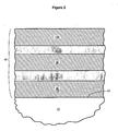
- Figure 3 depicts certain preferred embodiments wherein the coating 40 further comprises protective layers 80 and 180 positioned over the infrared-reflective layers 50 and 150, respectively.
- the coating 40 comprises, in sequence outwardly, a transparent dielectric base coat 30, a corrosion-resistant inner infrared-reflective layer 50, a first protective layer 80, a transparent dielectric middle coat 90, an outer infrared-reflective layer 150, a second protective layer 180, and a transparent dielectric outer coat 130.
- the layers are not required to be contiguous. Rather, other layers can be interposed among these layers, if so desired. In certain embodiments, though, these layers are provided in a contiguous sequence.
- the present low-emissivity coating 40 can be provided in many different layer structures each comprising the corrosion-resistant infrared-reflective layer 50, the transparent dielectric middle coat 90, and the outer infrared-reflective layer 150.
- the inner infrared-reflective layer 50 has a different composition (i.e., is formed of a different material) than the outer infrared-reflective layer 150.
- the outer infrared-reflective layer 150 consists essentially of silver, whereas the inner infrared-reflective layer 50 does not.
- the inner infrared-reflective layer comprises at least one metal (i.e., the "durable" metal) other than silver.
- the inner infrared-reflective layer 50 comprises a corrosion-resistant silver alloy.
- the inner infrared reflective layer 50 comprises an electrically conductive nitride. Embodiments of both types are particularly preferred.
- the inner infrared-reflective layer 50 comprises a corrosion-resistant silver alloy.
- silver is provided in combination with (i.e., in an alloy comprising) at least one durable metal.
- the durable metal can be a metal selected from the group consisting of platinum, palladium, copper, nickel, gold, indium, zinc, silicon, boron, and beryllium.
- the inner infrared-reflective layer 50 comprises a major portion (i.e., at least 50 atomic percent) of silver and a minor portion (i.e., less than 50 atomic percent) of the durable metal.
- atoms of the durable metal preferably account for less than about ten atomic percent of the metal atoms in the inner infrared-reflective layer 50.
- the percentage of the durable metal atoms relative to the total number of metal atoms in this layer 50 preferably is less than about 10%.
- the atomic percentage of the durable metal is less than about 1% (e.g., between 0.001% and 1.0%).
- the inner infrared-reflective layer 50 comprises silver and more than one durable metal
- the combined atomic percentage of the durable metals is preferably within one or more of the foregoing ranges.
- the inner infrared-reflective layer 50 comprises at least about 90 atomic percent (and perhaps optimally at least about 99 atomic percent) silver and at least one durable metal at an atomic percentage of less than about 10% (and perhaps optimally less than about one atomic percent).
- the inner infrared-reflective layer 50 comprises a corrosion-resistant silver alloy selected from the group consisting of silver-copper, silver-nickel, and silver-titanium.
- silver preferably is present in a major atomic percentage (i.e., at least 50%, desirably at least about 90%, and perhaps optimally at least about 99%). While these silver alloys are advantageous, the inner infrared-reflective layer 50 is not required to comprise any particular silver alloy.
- the corrosion-resistant inner infrared-reflective layer 50 comprises silver and copper (e.g., is a silver-copper alloy).
- the inner infrared-reflective layer 50 preferably comprises a major portion of silver and a minor portion of copper.
- Useful silver-copper alloys are described in U.S. Patent 4,462,883 .
- the alloy contains 1% to 30% copper with the remainder being silver.
- Preferred silver-copper alloys are described in U.S. Patent 4,883,721 .
- the alloy contains 5% to 10% copper with the remainder being silver. These particular alloys are preferred to silver-copper alloys that comprise more than 10% copper.
- a metal alloy target formed of silver and 1%-10% copper is sputtered (e.g., in an inert atmosphere) to deposit the inner infrared-reflective layer 50.
- the inner infrared-reflective layer 50 consists essentially of silver and copper.
- the corrosion-resistant inner infrared-reflective layer 50 comprises (e.g., is an alloy of) silver and palladium.
- the inner infrared-reflective layer 50 preferably comprises a major portion of silver and a minor portion of palladium.
- Useful silver-palladium alloys are described in U.S. Patent 6,280,811 .
- the major portion of silver is between 85 atomic percent and 99.9 atomic percent and the minor portion of palladium is between 0.1 atomic percent and 15 atomic percent.
- the major portion of silver is between 89 atomic percent and 99 atomic percent and the minor portion of palladium is between 1 atomic percent and 11 atomic percent.
- a metal alloy target formed of between 1 atomic percent and 11 atomic percent palladium (with the remainder being silver) is sputtered (e.g., in an inert atmosphere) to deposit the inner infrared-reflecting layer 50.
- the inner infrared-reflective layer 50 consists essentially of silver and palladium.
- the corrosion-resistant inner infrared-reflective layer 50 comprises (e.g., is an alloy of) silver, palladium, copper, and indium or zinc.
- the inner infrared-reflective layer 50 preferably comprises a major atomic percentage of silver. Useful alloys of these metals are described in U.S. Patent 5,037,708 .
- this alloy comprises 80% to 92.5% by weight silver, 4% to 9% by weight palladium, 2% to 10% by weight copper, and 0.5% to 1% by weight indium or zinc.
- the layer 50 is deposited by sputtering (e.g., in an inert atmosphere) a metal alloy target formed of 80% to 92.5% by weight silver, 4% to 9% by weight palladium; 2% to 10% by weight copper, and 0.5% to 1% by weight indium or zinc.
- the inner infrared-reflective layer 50 consists essentially of silver, palladium, copper, and indium or zinc.
- the corrosion-resistant inner infrared-reflective layer 50 comprises (e.g., is an alloy of) silver and gold.
- the inner infrared-reflective layer 50 preferably comprises a major portion of silver and a minor portion of gold.
- Useful silver-gold alloys are described in U.S. Patent 6,280.311 .
- this alloy comprises between 90 atomic percent and 99.9 atomic percent silver and between 0.1 atomic percent and 10 atomic percent gold. More preferably, the major portion of silver is between 91.5 atomic percent and 95 atomic percent and the minor portion of gold is between 5 atomic percent and 9.5 atomic percent.
- the layer 50 is deposited by sputtering (e.g., in an inert atmosphere) a metal alloy target formed of between 91.5 atomic percent and 95 atomic percent silver and between 5 atomic percent and 9.5 atomic percent gold. Accordingly, it will be appreciated that in certain embodiments, the inner infrared-reflective layer 50 consists essentially of silver and gold.
- the corrosion-resistant inner infrared-reflective layer 50 comprises (e.g. is an alloy of) silver, gold, and palladium.
- the inner infrared-reflective layer 50 preferably comprises a major portion of silver and minor portions of gold and palladium. Useful alloys of this nature are described in U.S. Patent 6,280,811 .
- this alloy comprises between 75 atomic percent and 99.8 atomic percent silver, between 0.1 atomic percent and 10 atomic percent gold, and between 0.1 atomic percent and 15 atomic percent palladium. More preferably, the major portion of silver is between 80.5 atomic percent and 94 atomic percent, the minor portion of gold is between 5 atomic percent and 9.5 atomic percent, and the minor portion of palladium is between 1 atomic percent and 10 atomic percent.
- the layer 50 is deposited by sputtering (e.g., in an inert atmosphere) a metal alloy target formed of between 80.5 atomic percent and 94 atomic percent silver, between 5 atomic percent and 9.5 atomic percent gold, and between 1 atomic percent and 10 atomic percent palladium.
- a metal alloy target formed of between 80.5 atomic percent and 94 atomic percent silver, between 5 atomic percent and 9.5 atomic percent gold, and between 1 atomic percent and 10 atomic percent palladium.
- the inner infrared-reflective layer 50 consists essentially of silver, gold, and palladium.
- the corrosion-resistant inner infrared-reflective layer 50 comprises (e.g., is an alloy of) silver and beryllium.
- the inner infrared-reflective layer 50 preferably comprises a major portion of silver and a minor portion of beryllium. Useful alloys of this type are described in U.S. Patent 6,280,811 .
- this alloy comprises between 90 atomic percent and 99.99 atomic percent silver and between 0.01 atomic percent and 10 atomic percent beryllium. More preferably, the major portion of silver is between 94 atomic percent and 99.9 atomic percent and the minor portion of beryllium is between 0.1 atomic percent and 6 atomic percent.
- the layer 50 is deposited by sputtering (e.g., in an inert atmosphere) a metal alloy target formed of between 94 atomic percent and 99.9 atomic percent silver and between 0.1 atomic percent and 6 atomic percent beryllium.
- the inner infrared-reflective layer 50 consists essentially of silver and beryllium.
- the corrosion-resistant inner infrared-reflective layer 50 comprises (e.g., is an alloy of) silver, zinc, copper, and silicon. Useful alloys of this nature are described in U.S. Patent 5,882,441 .
- this alloy comprises 90% to 94% by weight silver, 3.50% to 7.35% by weight zinc, 1 % to 3% by weight copper, and 0.1% to 2.5% by weight silicon.
- the layer 50 is deposited by sputtering (e.g., in an inert atmosphere) a metal alloy target formed of 90% to 94% by weight silver, 3.50% to 7.35% by weight zinc, 1% to 3% by weight copper, and 0.1% to 2.5% by weight silicon.
- the inner infrared-reflective layer 50 consists essentially of silver, zinc, copper, and silicon.
- the corrosion-resistant inner infrared-reflective layer 50 comprises (e.g., is an alloy of) silver, zinc, copper, nickel, silicon, and indium.
- Useful alloys of this nature are described in U.S. Patent 5,817,195 .
- this alloy comprises 90% to 92.5% by weight silver, 5.75% to 7.5% by weight zinc, 0.25% to less than 1% by weight copper, 0.25% to 0.5% by weight nickel, 0.1 % to 0.25% by Weight silicon, and 0.0% to 0.5% by weight indium.
- the layer 50 is deposited by sputtering (e.g., in an inert atmosphere) a metal alloy target formed of 90% to 92.5% by weight silver, 5.75% to 7.5% by weight zinc, 0.25% to less than 1 % by weight copper, 0.25% to 0.5% by weight nickel, 0.1% to 0.25% by weight silicon, and 0.0% to 0.5% by weight indium.
- a metal alloy target formed of 90% to 92.5% by weight silver, 5.75% to 7.5% by weight zinc, 0.25% to less than 1 % by weight copper, 0.25% to 0.5% by weight nickel, 0.1% to 0.25% by weight silicon, and 0.0% to 0.5% by weight indium.
- the layer 50 consists essentially of silver, zinc, copper, nickel, silicon, and indium.
- the corrosion-resistant inner infrared-reflective layer 50 comprises (e.g., is an alloy of) silver, silicon, boron, zinc, copper, tin, and indium.
- Useful alloys of this nature are described in U.S. Patent 5,039,479 .
- this alloy comprises 89% to 93.5% silver, 0.02% to 2% silicon, 0.001% to 2% boron, 0.5% to 5% zinc, 0.5% to 6% copper, 0.25% to 6% tin, and 0.01% to 1.25% indium.
- the layer 50 is deposited by sputtering (e.g., in an inert atmosphere) a metal alloy target formed of 89% to 93.5% silver, 0.02% to 2% silicon, 0.001% to 2% boron, 0.5% to 5% zinc, 0.5% to 6% copper, 0.25% to 6% tin, and 0.01 % to 1.25% indium.
- the inner infrared-reflective layer 50 consists essentially of silver, silicon, boron, zinc, copper, tin, and indium.
- the corrosion-resistant infrared-reflective layer 50 comprises an electrically-conductive nitride.
- Preferred conductive nitrides include chromium nitride, zirconium nitride, titanium nitride, and niobium nitride. These nitrides are both reflective and electrically conductive.
- the use of a conductive nitride for the inner infrared-reflective layer 50 is particularly desirable, as the chemical stability of the overall coating is greatly increased.
- the inner infrared-reflective layer is formed of a metallic film, it tends to oxidize when exposed to reactive oxygen. Nitride films tend to not oxidize as readily as metallic films. Therefore, in these embodiments, the coating 40 is particularly chemically stable, and will remain chemically stable over a particularly long period of time.
- a conductive nitride is used for the inner infrared-reflective layer 50
- This blocker layer 80 can be advantageously omitted in these embodiments since the inner infrared-reflective layer 50 is formed of a relatively non-reactive nitride, rather than a highly reactive silver layer.
- a transparent dielectric film can be deposited (e.g., as an oxide or nitride) directly over the inner infrared-reflective layer 50.
- the inner infrared-reflective layer 50 comprises at least one durable metal.
- the durable metal is a metal other than silver.
- the durable metal can be platinum, palladium, copper, nickel, gold, indium, zinc, silicon, boron, and beryllium.
- the inner infrared-reflective layer 50 comprises one of these durable metals.
- the inner infrared-reflective layer 50 can be a film consisting essentially of a nickel-based alloy that is corrosion resistant. Examples of corrosion-resistant nickel alloys include nichrome and nickel-aluminum. The term "nichrome" is used in its generic sense to designate a layer comprising some combination of nickel and chromium (e.g., 80% by weight nickel and 20% by weight chromium).
- the inner infrared-reflective layer 50 preferably has a thickness of between 50 ⁇ and 250 ⁇ , more preferably between 50 ⁇ and 180 ⁇ , and perhaps optimally between 65 ⁇ and 180 ⁇ .
- the outer infrared reflective layer 150 is somewhat thicker than the inner infrared-reflective layer 50.
- certain embodiments provide the inner infrared-reflective layer 50 at a thickness of between 50 ⁇ and 150 ⁇ , more preferably between 58 ⁇ and 90 ⁇ , and perhaps optimally 80 ⁇ , in combination with an outer infrared-reflective layer 150 at a thickness of between 90 ⁇ and 180 ⁇ , more preferably between 96 ⁇ and 155 ⁇ , and perhaps optimally about 130 ⁇ .
- the outer infrared-reflective layer 150 consists essentially of silver (e.g., is pure or essentially pure silver). Preferably, this layer 150 is deposited as metallic silver.
- the outer infrared-reflective layer 150 can be deposited by sputtering a metallic silver target in an argon atmosphere at a pressure of between about 3x10 -3 mbar and about 8x10 -3 mbar.
- the outer infrared-reflective layer 150 preferably has a thickness of between 50 ⁇ and 250 ⁇ , more preferably between 50 ⁇ and 180 ⁇ , and perhaps optimally between 65 ⁇ and 180 ⁇ .
- the transparent dielectric middle coat 90 preferably includes a layer consisting essentially of zinc oxide directly beneath the outer infrared-reflective layer 150. This facilitates the growth of silver having particularly low emissivity and particularly high visible transmission.
- the zinc oxide layer is preferably deposited as pure (or essentially pure) zinc oxide. For example, this layer can be deposited by sputtering a metallic zinc target in an argon/oxygen atmosphere at a pressure of between 4x10 -3 mbar and 8x10 -3 mbar.
- the thickness of this zinc oxide layer is desirably at least about 30 ⁇ , more preferably at least about 34 ⁇ , and perhaps optimally at least about 40 ⁇ (e.g., between 40 ⁇ and 250 ⁇ ). These minimum thicknesses are preferred to achieve the desired low emissivity and high visible transmission.
- the middle coat 90 preferably (though not necessarily) comprises a plurality of transparent dielectric layers.
- the layer directly beneath the outer infrared-reflective silver layer 150 preferably consists essentially of zinc oxide.
- the middle coat 90 consists of a single layer of zinc oxide.
- the zinc oxide layer typically has a thickness in the range of about 150-1200 ⁇ .
- Amorphous layers are advantageous in that they typically do not to experience major crystal growth when tempered or otherwise heat treated. As a result, they tend not to develop objectionable haze due to large crystal growth during heat treatment.
- amorphous layers tend to be relatively dense and thus provide a good barrier to oxygen, nitrogen, moisture, and other materials that may become somewhat mobile in the coating 40. Therefore, it is desirable to provide a middle coat 90 that includes at least one amorphous layer in combination with a layer of pure zinc oxide directly beneath the outer infrared-reflective silver layer 150. Exemplary middle coats 190 of this nature are described below.
- the middle coat 90 comprises at least two transparent dielectric layers. Whether the middle coat 90 consists of one or multiple transparent dielectric layers, the optical thickness (i.e., the product of refractive index and physical thickness) of the middle coat 90 preferably is about 300-2400 ⁇ .
- the middle coat 90 comprises a silicon nitride layer and a zinc oxide layer, with the zinc oxide layer positioned over (i.e., outwardly from) the silicon nitride layer and directly beneath the outer infrared-reflective silver layer 150. It is preferred to limit the thickness (e.g., to less than 200 ⁇ ) of each silicon nitride layer in the coating 40 to avoid undue stress.
- the middle coat 90 comprises a plurality of transparent dielectric layers.
- the middle coat 90 includes a silicon nitride layer positioned between two zinc oxide layers.
- the middle coat 90 comprises, moving outwardly from the optional first blocker layer 80: (1) zinc oxide at a thickness of 150-250 ⁇ , perhaps optimally about 220 ⁇ ; (2) silicon nitride at 6 thickness of 40-120A, perhaps optimally 80-100 ⁇ ; and (3) zinc oxide at a thickness of 150-250 ⁇ , perhaps optimally about 210 ⁇ . It is not required that these three intermediate layers be contiguous. However, the middle coat 190 can advantageously consist of a contiguous sequence of these three layers.
- the middle coat 90 comprises at least five transparent dielectric intermediate layers.
- each of the transparent dielectric intermediate layers has a thickness of less than 200 ⁇ .
- each transparent dielectric intermediate layer has a thickness of about 195 ⁇ or less.
- the middle coat comprises alternating oxide and nitride layers. In such cases, it is preferred for each intermediate nitride layer to have a smaller thickness than each intermediate oxide layer.
- the thickness of each intermediate nitride layer is less than about 180 ⁇ , while the thickness of each intermediate oxide layer may range up to about 195 ⁇ .
- the middle coat comprises alternating layers of a first, polycrystalline oxide (or suboxide) and a second, substantially amorphous nitride.
- alternating layers of zinc oxide and silicon nitride can be used (e.g., three layers of zinc oxide, two layers of silicon nitride).
- the middle coat 90 comprises, moving outwardly from the optional first blocker layer 80: (1) a first intermediate layer formed of zinc oxide at a thickness of 50-200 ⁇ , perhaps optimally about 105 ⁇ ; (2) a second intermediate layer formed of silicon nitride at a thickness of 50-200 ⁇ , perhaps optimally about 140 ⁇ ; (3) a third intermediate layer formed of zinc oxide at a thickness of 50-300 ⁇ , perhaps optimally about 200 ⁇ ; (4) a fourth intermediate layer formed of silicon nitride at a thickness of 50-200 ⁇ , perhaps optimally about 140 ⁇ ; and (5) a fifth intermediate layer formed of zinc oxide at a thickness of 50-200 ⁇ perhaps optimally about 80 ⁇ . While these five intermediate layers need not be contiguous, the middle coat can advantageously comprise a contiguous sequence of these five layers.
- the low-emissivity coating comprises, in sequence outwardly, a transparent base layer, a transparent dielectric base coat, a corrosion-resistant inner infrared-reflective layer, a transparent dielectric middle coat, and an outer infrared-reflective layer.
- the outer infrared-reflective layer consists essentially of silver and the corrosion-resistant inner infrared-reflective layer has a different composition (described above) than the outer infrared-reflective layer.
- the silicon dioxide is deposited directly over the substrate.
- the silicon dioxide has a thickness of less than 100 ⁇ (optimally between 50 ⁇ and 90 ⁇ ).
- the transparent dielectric base coat which is deposited over the silicon dioxide, comprises at least one transparent dielectric film.
- the transparent dielectric middle coat includes at least five transparent dielectric intermediate layers. In some cases, each of the transparent dielectric intermediate layers has a thickness of less than 200 ⁇ .
- the transparent dielectric middle coat includes a layer consisting essentially of zinc oxide directly beneath the outer infrared-reflective layer and the transparent dielectric base coat includes a durable transparent dielectric layer directly beneath the corrosion-resistant inner infrared-reflective layer, the durable transparent dielectric layer comprising a desired metal (described below), the desired metal being a metal other than zinc.
- each layer/film described in this paragraph is deposited by a conventional sputtering method.
- the corrosion-resistant inner infrared-reflective layer 50 is preferably (though not necessarily) positioned directly over a durable transparent dielectric layer comprising a metal other than zinc (preferably in a transparent dielectric compound that includes zinc and at least one other metal).
- the layer directly beneath the corrosion-resistant inner infrared-reflective layer 50 preferably is not pure zinc oxide. This goes against conventional wisdom, as pure zinc oxide, is strongly favored for use directly beneath each infrared-reflective layer in a low-emissivity coating. Surprisingly, the resulting durability, stress, and density benefits far outweigh the drawback of slightly increased emissivity.
- the layer directly beneath the corrosion-resistant inner infrared-reflective layer 50 comprises at least some tin, aluminum, bismuth, indium, titanium, niobium, and/or silicon.
- tin and aluminum are particularly preferred, and tin is uniquely preferred.
- this layer comprises an oxide of zinc in combination with (e.g., in a transparent dielectric compound also comprising) an oxide of at least one other metal.
- the inner infrared-reflective layer 50 is deposited directly over a durable transparent dielectric layer comprising a major portion of zinc oxide and a minor portion of an oxide of another metal (e.g., one of the "additional" or “desired” metals listed above in this paragraph).
- a durable transparent dielectric layer comprising a major portion of zinc oxide and a minor portion of an oxide of another metal (e.g., one of the "additional" or “desired” metals listed above in this paragraph).
- atoms of the additional metal account for less than about ten atomic percent relative to the total number of metal atoms in the durable transparent dielectric layer.
- the additional metal oxide will slightly increase the emissivity of the inner infrared reflective layer 50, as compared to the emissivity of the layer 50 if it were deposited directly over pure zinc oxide.
- the impact of the inner infrared-reflective layer 50 on the total emissivity of the coating 40 is surprisingly small compared to the impact of the outer infrared-reflective layer 150. Therefore, the use of a small amount of another metal oxide in a compound comprising zinc oxide will barely be detectable in terms of increased coating emissivity. Moreover, when the additional metal oxide is tin oxide or aluminum oxide (or a mixture thereof), the emissivity increase will be particularly small.
- the coating 40 includes all the elements of Figure 1 and further includes a base coat 30 and an outer coat 130.
- the base coat 30 and the outer coat 130 are optional, though preferred, in the present coating 40.
- the base coat 30 is provided directly over the surface 12 of the substrate 10.
- a transparent base layer (not shown) is formed directly over the surface 12 of the substrate 10 and the base coat 30 is formed directly over the transparent base layer.
- the transparent base layer is a silicon dioxide film having a thickness of less than 100 ⁇ (optimally between 50 ⁇ and 90 ⁇ ). Particularly advantageous transparent base layers are described in U.S. patent application 10/087,662 ( US6919133 )
- the preferred base coat 30 consists of a single transparent dielectric layer.
- the base coat 30 is preferably a durable transparent dielectric layer of the type described above.
- the base coat 30 is a single transparent dielectric layer comprising an oxide of zinc and at least one other metal.
- the single transparent dielectric layer can comprise at least some tin, aluminum, bismuth, indium, titanium, niobium, and/or silicon.
- the base coat 30 is a single zinc tin oxide layer, or a single zinc aluminum oxide layer, positioned directly beneath the corrosion-resistant inner infrared-reflective layer 50.
- the base coat 30 comprises a plurality of transparent dielectric layers.
- the layer directly beneath the corrosion-resistant inner infrared-reflective layer 50 preferably is a durable transparent dielectric layer of the type described above.
- the base coat 30 comprises multiple transparent dielectric layers including at least one durable transparent dielectric layer comprising a metal other than zinc, (e.g., comprising at least some tin, aluminum, bismuth, indium, titanium, niobium, and/or silicon).
- the base coat 30 includes at least one durable transparent dielectric layer comprising zinc tin oxide and/or zinc aluminum, oxide.
- the durable transparent dielectric layer preferably is directly beneath the inner infrared-reflective layer 50.
- the base coat 30 can comprise any number of transparent dielectric layers. Whether the base coat 30 consists of one or multiple transparent dielectric layers, the optical thickness of the base coat 30 preferably is between 150 ⁇ and 1200 ⁇ .
- transparent dielectric is used herein to refer to any non-metallic (i.e., neither a pure metal nor a metal alloy) compound that comprises any one or more metals and is substantially transparent when applied as a thin film. Included in this definition would be any metal oxide, metal nitride, metal carbide, metal sulfide, metal boride, etc. (and any combinations thereof, such as oxynitrides).
- Exemplary metal oxides include oxides of zinc, tin, indium, bismuth, titanium, hafnium, zirconium, and mixtures thereof. Metal oxides tend to be advantageous due to their ease and low cost of application. However, metal nitrides (e.g., silicon nitride) can also be used quite advantageously.
- metal is to be understood to include all metals and semi-metals (i.e., metalloids), such as silicon.
- the present coating 40 preferably includes an outer coat 130 positioned further from the substrate 10 than the outer infrared-reflective layer 150.
- the preferred outer coat 130 comprises at least one transparent dielectric layer.
- the preferred outer coat 130 consists of a single transparent dielectric layer.
- a wide variety of transparent dielectric films can be used as the outermost layer of the present coating 40.
- a chemically and mechanically durable material is used when the outer coat 130 is a single layer.
- certain embodiments employ an outer coat 130 formed by a single layer of silicon nitride, titanium dioxide, or tin oxide, each of which offers-relatively good chemical and mechanical durability.
- the outer coat 130 comprises a plurality of transparent dielectric layers. Whether the outer coat 130 consists of one or multiple transparent dielectric layers, the optical thickness of the outer coat 130 preferably is between 150 ⁇ and 1200 ⁇ .
- a variety of film stacks are well known by skilled artisans to be suitable for use as the outer coat of a low-emissivity coating, and any such film stack can be used as the outer coat 130 of the present coating 40.
- each layer of the outer coat 130, as well as each layer of the base 30 and middle 90 coats may be preferable to limit each layer of the outer coat 130, as well as each layer of the base 30 and middle 90 coats, to a physical thickness of no more than about 250 ⁇ , more preferably no more than about 225 ⁇ , and perhaps optimally less than 200 ⁇ .
- each layer in the outer coat 130, as well as each layer in the base 30 and middle 90 coats is formed of a different material than each layer contiguous thereto. As described in U.S. patent application 09/728,435 ( US2002-0102352 ). this is believed to reduce the likelihood that objectionable haze will develop in the coating during heat treatment.
- the outer coat 130 comprises at least two transparent dielectric layers.
- a first outer layer can be deposited directly upon the optional second blocker layer 180 and a second outer layer can be deposited directly upon this first outer layer.
- the first outer layer can be formed of any desired transparent dielectric material, such as zinc oxide.
- the thickness of the first outer layer is preferably between 25 ⁇ and 300 ⁇ , more preferably between 50 ⁇ and 275 ⁇ , and perhaps optimally between 70 ⁇ and 250 ⁇ .
- the second outer layer can be formed of any desired transparent dielectric material, although it is preferably formed of material having good chemical and mechanical durability. For example, this layer can be advantageously formed of silicon nitride.
- the thickness of the second outer layer is preferably between 25 ⁇ and 300 ⁇ , more preferably between 50 ⁇ and 275 ⁇ , and perhaps optimally between 70 ⁇ and 250 ⁇ .
- the first outer layer is formed of zinc oxide at a thickness of about 175 ⁇ and the second outer layer is formed of silicon nitride at a thickness of about 75 ⁇ .
- the first outer layer is formed of zinc oxide at a thickness of about 225 ⁇ and the second outer layer is formed of silicon nitride at a thickness of about 96 ⁇ .
- the coating 40 includes all the elements of Figure 2 and further includes protective (or “barrier” or “blocker”) layers 80, 180 positioned directly over the infrared-reflective layers 50 and 150, respectively.
- the protective layers 80, 180 are preferred, though not strictly required, in the coating 40.
- the protective layers 80, 180 are preferably provided to protect the underlying infrared-reflective layers from chemical attack and to provide resistance to deterioration (e.g., oxidation) of the infrared-reflective layers during deposition of subsequent layers and/or during heat treatment.
- An additional or alternative purpose for each protective layer may be to enhance the adhesion of the next-applied layer to the underlying infrared-reflective film.
- the protective layers 80,' 180 can be provided as stress-reducing layers in some embodiments (e.g., wherein the protective layers comprise nickel-chromium compounds). Further, the thickness of the protective layers 80, 180 can be varied to adjust the color and/or shading properties of the coating 40.
- Each protective layer can be deposited as a layer comprising a metal selected from the group consisting of titanium, niobium, nickel, and chromium. Further, skilled artisans may wish to select other known materials for use in the protective layers 80, 180.
- the protective layers 80, 180 are preferably each applied at a thickness of 7-30 ⁇ , more preferably 15-22 ⁇ , and perhaps optimally about 20 ⁇ .
- each layer is deposited by sputtering.
- Sputtering techniques and equipment are well known in the present art.
- magnetron sputtering chambers and related equipment are commercially available from a variety of sources (e.g., Leybold and BOC Coating Technology).
- Useful magnetron sputtering techniques and equipment are also disclosed in U.S. Patent 4,166,018 (Chapin ) .
- magnetron sputtering involves providing at least one target formed of material to be deposited upon a substrate.
- a clean substrate e.g., glass
- a coating chamber which is evacuated (commonly to a pressure of less than 10 -4 torr, more commonly to less than 2 ⁇ 10 -5 torr).
- the target is provided with a negative charge and a relatively positively charged anode is positioned adjacent the target.
- Particles e.g., ions
- Particles in the plasma collide with the target, ejecting target material from the target and sputtering it onto the substrate.
- the invention provides methods of producing coated substrates, e.g., by depositing a corrosion-resistant low-emissivity coating onto a substrate.
- the method typically comprises providing a substrate having a desired surface (e.g., a major surface) and depositing a low-emissivity coating of the type described above onto the desired surface.
- the method comprises depositing upon the desired surface a low-emissivity coating comprising, in sequence outwardly, an optional base coat 30, a corrosion-resistant inner infrared-reflective layer 50, an optional first blocker layer 80, a transparent dielectric middle coat 90, an outer infrared-reflective layer 150, an optional second blocker layer 180, and an optional outer coat 130.
- the method comprises depositing the outer infrared-reflective layer 150 as a film consisting essentially of silver and depositing the corrosion-resistant inner infrared-reflective layer 50 as a film having a different composition than the outer infrared-reflective layer 150.
- the corrosion-resistant inner infrared-reflective layer 50 is deposited as a film comprising at least one metal other than silver.
- this layer 150 can be advantageously deposited as a film comprising at least one durable metal selected from the group consisting of platinum, palladium, copper, nickel, gold, indium, zinc, silicon, boron, and beryllium.
- the inner infrared-reflective layer 50 can be advantageously deposited as a corrosion-resistant silver alloy, e.g., comprising a major atomic percentage of silver and a minor atomic percentage of at least one metal other than silver).
- Each layer in the low-emissivity coating 40 preferably is deposited by sputtering.
- a zinc tin oxide layer was deposited.
- This zinc tin oxide layer had a thickness of about 147 ⁇ .
- a silver alloy layer comprising silver and palladium.
- the silver alloy layer had a thickness of 60-70 ⁇ .
- Directly upon the silver alloy layer was deposited a layer of titanium.
- This titanium layer was deposited at a thickness of 17-23 ⁇ ,
- Directly, upon this layer of titanium was deposited a layer of zinc oxide.
- This zinc oxide layer was deposited in an oxidizing atmosphere and therefore the underlying titanium layer was partially oxidized.
- This zinc oxide layer had a thickness of about 175 ⁇ .
- a layer of silicon dioxide was deposited.
- the silicon dioxide layer had a thickness of about 60 ⁇ .
- a layer of zinc tin oxide was deposited a layer of zinc tin oxide.
- This layer of zinc tin oxide had a thickness of about 140 ⁇ .
- a silver alloy layer comprising silver and palladium.
- the silver alloy layer had a thickness of about 71 ⁇ .
- a protective layer of niobium was deposited a protective layer of niobium.
- This protective layer of niobium had a thickness of about 18 ⁇ .
- this protective layer of niobium was deposited a layer of zinc oxide.
- This layer of zinc oxide was deposited at a thickness of about 105 ⁇ . Directly upon this layer of zinc oxide was deposited a layer of silicon nitride. This silicon nitride layer had a thickness of about 124 ⁇ . Directly upon this layer of silicon nitride was deposited another layer of zinc oxide. This zinc oxide layer was deposited at a thickness of about 124 ⁇ . Directly upon this layer of zinc oxide was deposited another layer of silicon nitride. This silicon nitride layer had a thickness of about 124 ⁇ . Directly upon this layer of silicon nitride was deposited another layer of zinc oxide. This zinc oxide layer had a thickness of about 113 ⁇ . Directly upon this layer of zinc oxide was deposited a layer of silver.
- the silver layer had a thickness of about 116 ⁇ .
- a protective layer of niobium was deposited.
- This layer of niobium had a thickness of about 18 ⁇ .
- Directly upon this layer of niobium was deposited a layer of zinc oxide.
- This layer of zinc oxide had a thickness of about 100 ⁇ .
- Directly upon this layer of zinc oxide was deposited a layer of silicon nitride.
- This layer of silicon nitride had a thickness of about 40 ⁇ .
- Directly upon this layer of silicon nitride was deposited a layer of titanium nitride.
- the layer of titanium nitride had a thickness of about 16 ⁇ .
- Directly upon the layer of titanium nitride was deposited a layer of silicon nitride. This layer of silicon nitride (which was the outermost layer of the coating) had a thickness of about 122 ⁇ .
Landscapes
- Chemical & Material Sciences (AREA)
- Life Sciences & Earth Sciences (AREA)
- Engineering & Computer Science (AREA)
- Chemical Kinetics & Catalysis (AREA)
- General Chemical & Material Sciences (AREA)
- Geochemistry & Mineralogy (AREA)
- Materials Engineering (AREA)
- Organic Chemistry (AREA)
- Laminated Bodies (AREA)
- Surface Treatment Of Glass (AREA)
- Physical Vapour Deposition (AREA)
- Paints Or Removers (AREA)
Abstract
Description
- The present invention provides coatings for glass and other substrates. More specifically, this invention provides low-emissivity coatings. The invention also provides methods for depositing coatings of this nature, as well as substrates bearing these coatings.
- Low-emissivity coatings for glass and other substrates are well known in the present art. Typically, they include one or more infrared-reflective layers each positioned between two or more transparent dielectric layers. The infrared-reflective layers reduce the transmission of radiant heat through the coating (e.g., by reflecting infrared radiation). These infrared-reflective layers typically comprise conductive metals, such as silver, gold, or copper. The transparent dielectric layers are used primarily to reduce visible reflectance and to control other coating properties, such as color. Commonly used transparent dielectrics include oxides of zinc, tin, and titanium, as well as nitrides, such as silicon nitride.
- In most cases, each infrared-reflective layer in a low-emissivity coating comprises silver. Silver is the most commonly used infrared-reflective material because it provides high electrical conductivity (and hence low-emissivity), high visible transmission, and neutral color. A drawback of using silver for each infrared-reflective layer is that silver lacks mechanical and chemical durability. Silver layers are very soft and thus limit the mechanical durability of silver-based coatings. Silver layers are also particularly vulnerable to becoming corroded. Thus, great care must be exercised to prevent silver-based coatings from being damaged. For example, consider manufacturing periods (e.g., prior to and/or during assembly of coated substrates into IG units). During these periods, coated substrates are frequently subjected to relatively harsh conditions. For example, the conditions associated with handling, shipping, and washing can cause silver-based coatings to become scratched or otherwise abraded. During manufacturing periods, coated substrates are also commonly exposed to air, moisture, and other chemicals, all of which can cause silver to become corroded. Thus, when pure silver layers are used in a low-emissivity coating, the overall durability of the coating tends to be less than ideal.
- Attempts have been made to enhance the durability of infrared-reflective layers. For example, some have replaced the inner and outer silver layers with layers of a more durable reflective metal. Others have replaced the inner and outer silver layers with layers of a silver alloy comprising a small amount of a more durable reflective metal. For example, alloys of silver and palladium have reportedly been found to create infrared-reflective layers with greater durability than pure silver. These alternatives, however, have largely been rejected in the marketplace, as they are predominately viewed as yielding unacceptably high emissivity. Therefore, pure silver is typically used for each infrared-reflective layer in a low-emissivity coating, notwithstanding its mechanical and chemical vulnerability.
- The properties of an infrared-reflective silver layer depend upon the surface over which it is deposited. For example, a silver layer can be grown to have particularly low emissivity by depositing the silver layer directly over a film of pure zinc oxide. Thus, it is a widespread practice in the art to position each infrared-reflective silver layer in a low-emissivity coating directly over a pure zinc oxide layer.
- While zinc oxide is beneficial for growing a high quality silver film, it has several drawbacks. One known drawback is that, because zinc oxide is a highly crystalline film, it is not particularly dense. Thus, pure zinc oxide layers tend to be less than ideal for preventing air, moisture, sodium ions, and other materials from migrating through the zinc oxide layers and potentially reaching and reacting with the silver layers. Further, when zinc oxide is deposited by sputtering, it tends to exhibit pinholes more frequently than would be ideal. Great care is taken to avoid pinholes, as they can also give air, moisture, and other chemicals access to the silver layers. Another drawback of zinc oxide is that thick zinc oxide layers tend to exhibit more stress than is preferred. This can result in less than optimal adhesion, hence creating the potential for delamination. Notwithstanding these drawbacks, it is conventional in the art to provide pure zinc oxide directly beneath each silver layer in a low-emissivity coating.
-
WO01/44131 EP 0 963 960 discloses low emissivity coatings on a glass substrate, the coating including two infrared reflective layers each having the same composition. - It would be desirable to provide a low-emissivity coating that achieves better durability than conventional low-emissivity coatings wherein each infrared-reflective layer is pure silver. It would be particularly desirable to provide a coating that achieves this result without an undue increase in emissivity.
- The present invention is directed to a substrate bearing a low-emissivity coating. The coating comprises, in sequence outwardly (i.e., moving away from the substrate), a corrosion-resistant inner infrared-reflective layer, a transparent dielectric middle coat, and an outer infrared-reflective layer. The outer infrared-reflective layer consists, essentially of silver and the corrosion-resistant inner infrared-reflective layer has a different composition than the outer infrared-reflective layer. Preferably, the transparent middle coat comprises a layer consisting essentially of zinc oxide positioned directly beneath the outer infrared-reflective layer. This zinc oxide layer typically has a thickness of at least about 40Å.
- In some cases, the inner infrared-reflective layer comprises a corrosion-resistant silver alloy. Preferably, the alloy comprises a major portion of silver and a minor portion of a durable metal, the durable metal being a metal other than silver. Perhaps optimally, atoms of the durable metal account for less than about 10 atomic percent of the total number of metal atoms in the inner infrared-reflective layer. Preferably, the durable metal is a metal selected from the group consisting of platinum, palladium, copper, nickel, gold, indium, zinc, silicon, boron and beryllium.
- In other cases, the corrosion-resistant inner infrared-reflective layer comprises an electrically conductive nitride. The electrically-conductive nitride is preferably a nitride selected from the group consisting of chromium nitride, zirconium nitride, titanium nitride, and niobium nitride.
- In certain embodiments, the low-emissivity coating further comprises a transparent dielectric base coat between the substrate and the corrosion-resistant inner infrared-reflective layer. This transparent base coat typically comprises a durable transparent dielectric layer positioned directly beneath the corrosion-resistant inner-infrared reflective layer. Preferably, the durable transparent dielectric layer comprises a desired metal other than zinc. This desired metal can be a metal selected from the group consisting of tin, aluminum, bismuth, indium, titanium, niobium, and silicon. In some cases, the durable transparent dielectric layer comprises both zinc and the desired metal. For example, the durable transparent dielectric layer can comprise a major portion of zinc oxide and a minor portion of an oxide of the desired metal. Perhaps optimally, the durable transparent dielectric layer comprises zinc tin oxide and/or zinc aluminum oxide. In some cases, atoms of the desired metal account for less than about 10 atomic percent of the total metal atoms in the durable transparent dielectric layer. In some embodiments, the low-emissivity coating further comprises a transparent dielectric outer coat further from the substrate than the outer infrared-reflective layer.
- In certain particularly preferred embodiments, the invention provides a substrate bearing a low-emissivity coating comprising, in sequence outwardly, a transparent base layer, a transparent dielectric base coat, a corrosion-resistant inner infrared reflective layer, a transparent dielectric middle coat, and an outer infrared-reflective layer. In these embodiments, the outer infrared-reflective layer consists essentially of silver and the corrosion-resistant inner infrared-reflective layer has a different composition than the outer infrared-reflective layer. Here, the silicon dioxide is deposited directly over the substrate. Conjointly, the transparent dielectric base coat comprises at least one transparent dielectric film. Further, the transparent dielectric middle coat includes at least five transparent dielectric intermediate layers. Preferably, though not necessarily, the silicon dioxide has a thickness of less than 100Å. In some preferred embodiments, each of the transparent dielectric intermediate layers has a thickness of less than 200Å. In some cases, all the preferred features described in this paragraph are provided in combination and the transparent dielectric middle coat includes a layer consisting essentially of zinc oxide directly beneath the outer infrared-reflective layer and the transparent dielectric base coat includes a durable transparent dielectric layer directly beneath the corrosion-resistant inner infrared-reflective layer, the durable transparent dielectric layer comprising a desired metal, the desired metal, being a metal other than zinc. In certain related methods, each layer/film described in this paragraph is deposited by a conventional sputtering method.
- The invention also provides methods of producing coated substrates, e.g., by depositing a low-emissivity coating on a substrate. Typically, the method comprises providing a substrate having a surface, and depositing the low-emissivity coating onto this surface. Preferably, this involves depositing a low-emissivity coating comprising, moving outwardly from the substrate, a corrosion-resistant inner infrared-reflective layer, a transparent dielectric middle coat, and an outer infrared-reflective layer. Typically, the outer infrared-reflective layer is deposited as a film consisting essentially of silver and the inner infrared-reflective layer is deposited as a film having a different composition than the outer infrared-reflective layer. Preferably, the deposition of the transparent dielectric middle coat includes depositing a layer consisting essentially of zinc oxide directly beneath the outer infrared-reflective layer. In some cases, this zinc oxide layer is deposited at a thickness of at least about 40 angstroms. In certain favored methods, the middle coat is formed by deposited at least five intermediate films (as described). In some of the present embodiments, the inner infrared-reflective layer is deposited as a film comprising a corrosion-resistant silver alloy. For example, the inner infrared-reflective layer can be deposited as a film comprising a major portion of silver and a minor portion of a durable metal, the durable metal being a metal other than silver. Here, the inner infrared-reflective layer is preferably deposited as a film wherein atoms of the durable metal account for less than about 10 atomic percent relative to the total number of metal atoms in the inner infrared-reflective layer. In some cases, the inner infrared-reflective layer is deposited as a film comprising silver and a durable metal selected from the group consisting of platinum, palladium, copper, nickel, gold, indium, zinc, silicon, boron, and beryllium. The inner infrared-reflective layer can alternatively be deposited as a film comprising an electrically-conductive nitride. When this is done, the deposition of the middle coat can optionally include depositing an oxide or nitride layer directly over the electrically-conductive nitride of the inner infrared-reflective layer. In some cases, the inner infrared-reflective layer is deposited as a film comprising an electrically conductive nitride selected from the group consisting of chromium nitride, zirconium nitride, titanium nitride, and niobium nitride. If so desired, the present method can further comprise depositing a transparent dielectric base coat between the substrate and the corrosion-resistant inner infrared-reflective layer, the transparent dielectric base coat including a durable transparent dielectric layer directly beneath the corrosion-resistant inner infrared-reflective layer, the durable transparent dielectric layer comprising a desired metal, the desired metal being a metal other than zinc. For example, the durable transparent dielectric layer can be deposited as a film comprising a desired metal selected from the group consisting of tin, aluminum, bismuth, indium, titanium, niobium, and silicon Preferably, the durable transparent dielectric layer is deposited as a film comprising zinc and the desired metal. For example, the durable transparent dielectric layer can be deposited as a film comprising a major portion of zinc oxide and a minor portion of an oxide of the desired metal. In some cases, the durable transparent dielectric layer is deposited as a film wherein atoms of the desired metal account for less than about 10 atomic percent relative to the total number of metal atoms in the durable transparent dielectric layer. Perhaps optimally, the durable transparent dielectric layer is deposited as a film comprising zinc tin oxide and/or zinc aluminum oxide. In some cases, the method further comprises depositing a transparent dielectric outer coat further from the substrate than the outer infrared-reflective layer. Preferably, each layer in the coating is deposited on the substrate by sputtering.
-
-
Figure 1 is a schematic cross-sectional view of a coating in accordance with, certain embodiments of the present invention; -
Figure 2 is a schematic cross-sectional view of a coating in accordance with certain embodiments of the invention; and -
Figure 3 is a schematic cross-sectional view of a coating in accordance with certain embodiments of the invention. - The following detailed description is to be read with reference to the Figures, in which like elements in different Figures have like reference numerals. The Figures, which are not necessarily to scale, depict selected embodiments and are not intended to limit the scope of the invention. Skilled artisans will recognize that the examples provided herein have many useful alternatives that fall within the scope of the invention.
- The present invention provides a corrosion-resistant low-emissivity coating for glass and other substrates. It has been discovered that the outer infrared-reflective layer in a "double-type" low-emissivity coating has a far greater impact on the total emissivity of the coating than does the inner infrared-reflective layer. In fact, the impact of the inner infrared-reflective layer on the coating's emissivity is surprisingly small. Thus, in a coating of the present invention, the inner infrared-reflective silver layer is replaced with a layer of a more durable (particularly more corrosion resistant) infrared-reflective material. Surprisingly, the present coating achieves a substantial increase in overall coating durability (particularly in corrosion resistance) with very little increase in overall coating emissivity.
- The invention provides a
substrate 10 bearing a corrosion-resistant low-emissivity coating 40. A variety of substrates are suitable for use in the present invention. In most cases, the substrate is a sheet of transparent material (i.e., a transparent sheet). However, the substrate is not required to be transparent. For example, opaque substrates may be useful in some cases. However, it is anticipated that for most applications, the substrate will comprise a transparent or translucent material, such as glass or clear plastic. In many cases, the substrate will be a glass pane. A variety of known glass types can be used, and soda-lime glass is expected to be preferred. -
Figure 1 depicts an alternate embodiment of thepresent coating 40, wherein the coating comprises, in sequence outwardly (i.e., moving away from the substrate) a corrosion-resistant inner infrared-reflective layer 50, a transparent dielectricmiddle coat 90, and an outer infrared-reflective layer 150. Thus, the outer infrared-reflective layer 150 is further from thesubstrate 10 than the transparent dielectricmiddle coat 90, and the transparent dielectricmiddle coat 90 is further from thesubstrate 10 than the corrosion-resistant inner infrared-reflective layer 50. These layers need not be provided in a contiguous sequence, as will be apparent in view of the ensuing discussion. -
Figure 2 depicts certain preferred embodiments wherein thecoating 40 further comprises abase coat 30 and anouter coat 130. While thebase 30 and outer 130 coats are optional, both are preferred. Thus, in certain preferred embodiments, thecoating 40 comprises, in sequence outwardly, a transparentdielectric base coat 30, a corrosion-resistant inner infrared-reflective layer 50, a transparent dielectricmiddle coat 90, an outer infrared-reflective layer 150, and a transparent dielectricouter coat 130. Again, these layers need not be contiguous. - For example,
Figure 3 depicts certain preferred embodiments wherein thecoating 40 further comprisesprotective layers reflective layers coating 40 comprises, in sequence outwardly, a transparentdielectric base coat 30, a corrosion-resistant inner infrared-reflective layer 50, a firstprotective layer 80, a transparent dielectricmiddle coat 90, an outer infrared-reflective layer 150, a secondprotective layer 180, and a transparent dielectricouter coat 130. Here again, the layers are not required to be contiguous. Rather, other layers can be interposed among these layers, if so desired. In certain embodiments, though, these layers are provided in a contiguous sequence. - While certain preferred embodiments are detailed in this disclosure, it will be apparent to skilled artisans that the present low-
emissivity coating 40 can be provided in many different layer structures each comprising the corrosion-resistant infrared-reflective layer 50, the transparent dielectricmiddle coat 90, and the outer infrared-reflective layer 150. - In the
present coating 40, the inner infrared-reflective layer 50 has a different composition (i.e., is formed of a different material) than the outer infrared-reflective layer 150. In particular, the outer infrared-reflective layer 150 consists essentially of silver, whereas the inner infrared-reflective layer 50 does not. Instead, the inner infrared-reflective layer comprises at least one metal (i.e., the "durable" metal) other than silver. In some embodiments, the inner infrared-reflective layer 50 comprises a corrosion-resistant silver alloy. In other embodiments, the inner infraredreflective layer 50 comprises an electrically conductive nitride. Embodiments of both types are particularly preferred. - Thus, in some embodiments, the inner infrared-
reflective layer 50 comprises a corrosion-resistant silver alloy. Here, silver is provided in combination with (i.e., in an alloy comprising) at least one durable metal. The durable metal can be a metal selected from the group consisting of platinum, palladium, copper, nickel, gold, indium, zinc, silicon, boron, and beryllium. Preferably, the inner infrared-reflective layer 50 comprises a major portion (i.e., at least 50 atomic percent) of silver and a minor portion (i.e., less than 50 atomic percent) of the durable metal. For example, atoms of the durable metal preferably account for less than about ten atomic percent of the metal atoms in the inner infrared-reflective layer 50. In other words, the percentage of the durable metal atoms relative to the total number of metal atoms in thislayer 50 preferably is less than about 10%. Perhaps optimally, the atomic percentage of the durable metal is less than about 1% (e.g., between 0.001% and 1.0%). In embodiments wherein the inner infrared-reflective layer 50 comprises silver and more than one durable metal, the combined atomic percentage of the durable metals is preferably within one or more of the foregoing ranges. Thus, in certain preferred embodiments, the inner infrared-reflective layer 50 comprises at least about 90 atomic percent (and perhaps optimally at least about 99 atomic percent) silver and at least one durable metal at an atomic percentage of less than about 10% (and perhaps optimally less than about one atomic percent). - In certain preferred embodiments, the inner infrared-
reflective layer 50 comprises a corrosion-resistant silver alloy selected from the group consisting of silver-copper, silver-nickel, and silver-titanium. In these embodiments, silver preferably is present in a major atomic percentage (i.e., at least 50%, desirably at least about 90%, and perhaps optimally at least about 99%). While these silver alloys are advantageous, the inner infrared-reflective layer 50 is not required to comprise any particular silver alloy. - In one particular embodiment, the corrosion-resistant inner infrared-
reflective layer 50 comprises silver and copper (e.g., is a silver-copper alloy). In this embodiment, the inner infrared-reflective layer 50 preferably comprises a major portion of silver and a minor portion of copper. Useful silver-copper alloys are described inU.S. Patent 4,462,883 . - Here, the alloy contains 1% to 30% copper with the remainder being silver. Preferred silver-copper alloys are described in
U.S. Patent 4,883,721 . - In this patent, the alloy contains 5% to 10% copper with the remainder being silver. These particular alloys are preferred to silver-copper alloys that comprise more than 10% copper. Thus, in certain preferred methods, a metal alloy target formed of silver and 1%-10% copper is sputtered (e.g., in an inert atmosphere) to deposit the inner infrared-
reflective layer 50. Accordingly, it will be appreciated that in certain embodiments, the inner infrared-reflective layer 50 consists essentially of silver and copper. - In other embodiments, the corrosion-resistant inner infrared-
reflective layer 50 comprises (e.g., is an alloy of) silver and palladium. In these embodiments; the inner infrared-reflective layer 50 preferably comprises a major portion of silver and a minor portion of palladium. Useful silver-palladium alloys are described inU.S. Patent 6,280,811 . - Here, the major portion of silver is between 85 atomic percent and 99.9 atomic percent and the minor portion of palladium is between 0.1 atomic percent and 15 atomic percent. Preferably, the major portion of silver is between 89 atomic percent and 99 atomic percent and the minor portion of palladium is between 1 atomic percent and 11 atomic percent. Thus, in certain preferred methods, a metal alloy target formed of between 1 atomic percent and 11 atomic percent palladium (with the remainder being silver) is sputtered (e.g., in an inert atmosphere) to deposit the inner infrared-reflecting
layer 50. Accordingly, it will be appreciated that in certain embodiments, the inner infrared-reflective layer 50 consists essentially of silver and palladium. - In some embodiments, the corrosion-resistant inner infrared-
reflective layer 50 comprises (e.g., is an alloy of) silver, palladium, copper, and indium or zinc. In these embodiments, the inner infrared-reflective layer 50 preferably comprises a major atomic percentage of silver. Useful alloys of these metals are described inU.S. Patent 5,037,708 . - Preferably, this alloy comprises 80% to 92.5% by weight silver, 4% to 9% by weight palladium, 2% to 10% by weight copper, and 0.5% to 1% by weight indium or zinc. Thus, in certain preferred methods, the
layer 50 is deposited by sputtering (e.g., in an inert atmosphere) a metal alloy target formed of 80% to 92.5% by weight silver, 4% to 9% by weight palladium; 2% to 10% by weight copper, and 0.5% to 1% by weight indium or zinc. Accordingly, it will be appreciated that in certain embodiments, the inner infrared-reflective layer 50 consists essentially of silver, palladium, copper, and indium or zinc. - In other embodiments, the corrosion-resistant inner infrared-
reflective layer 50 comprises (e.g., is an alloy of) silver and gold. In these embodiments, the inner infrared-reflective layer 50 preferably comprises a major portion of silver and a minor portion of gold. Useful silver-gold alloys are described inU.S. Patent 6,280.311 .
Preferably, this alloy comprises between 90 atomic percent and 99.9 atomic percent silver and between 0.1 atomic percent and 10 atomic percent gold. More preferably, the major portion of silver is between 91.5 atomic percent and 95 atomic percent and the minor portion of gold is between 5 atomic percent and 9.5 atomic percent. Thus, in certain more preferred methods, thelayer 50 is deposited by sputtering (e.g., in an inert atmosphere) a metal alloy target formed of between 91.5 atomic percent and 95 atomic percent silver and between 5 atomic percent and 9.5 atomic percent gold. Accordingly, it will be appreciated that in certain embodiments, the inner infrared-reflective layer 50 consists essentially of silver and gold. - In some embodiments, the corrosion-resistant inner infrared-
reflective layer 50 comprises (e.g. is an alloy of) silver, gold, and palladium. In these embodiments, the inner infrared-reflective layer 50 preferably comprises a major portion of silver and minor portions of gold and palladium. Useful alloys of this nature are described inU.S. Patent 6,280,811 . - Preferably, this alloy comprises between 75 atomic percent and 99.8 atomic percent silver, between 0.1 atomic percent and 10 atomic percent gold, and between 0.1 atomic percent and 15 atomic percent palladium. More preferably, the major portion of silver is between 80.5 atomic percent and 94 atomic percent, the minor portion of gold is between 5 atomic percent and 9.5 atomic percent, and the minor portion of palladium is between 1 atomic percent and 10 atomic percent. Thus, in certain more preferred methods, the
layer 50 is deposited by sputtering (e.g., in an inert atmosphere) a metal alloy target formed of between 80.5 atomic percent and 94 atomic percent silver, between 5 atomic percent and 9.5 atomic percent gold, and between 1 atomic percent and 10 atomic percent palladium. Accordingly, it will be appreciated that, in certain embodiments, the inner infrared-reflective layer 50 consists essentially of silver, gold, and palladium. - In other embodiments, the corrosion-resistant inner infrared-
reflective layer 50 comprises (e.g., is an alloy of) silver and beryllium. In these embodiments, the inner infrared-reflective layer 50 preferably comprises a major portion of silver and a minor portion of beryllium. Useful alloys of this type are described inU.S. Patent 6,280,811 . - Preferably, this alloy comprises between 90 atomic percent and 99.99 atomic percent silver and between 0.01 atomic percent and 10 atomic percent beryllium. More preferably, the major portion of silver is between 94 atomic percent and 99.9 atomic percent and the minor portion of beryllium is between 0.1 atomic percent and 6 atomic percent. Thus, in certain more preferred methods, the
layer 50 is deposited by sputtering (e.g., in an inert atmosphere) a metal alloy target formed of between 94 atomic percent and 99.9 atomic percent silver and between 0.1 atomic percent and 6 atomic percent beryllium. Accordingly, in certain embodiments, the inner infrared-reflective layer 50 consists essentially of silver and beryllium. - In some embodiments, the corrosion-resistant inner infrared-
reflective layer 50 comprises (e.g., is an alloy of) silver, zinc, copper, and silicon. Useful alloys of this nature are described inU.S. Patent 5,882,441 . - Preferably, this alloy comprises 90% to 94% by weight silver, 3.50% to 7.35% by weight zinc, 1 % to 3% by weight copper, and 0.1% to 2.5% by weight silicon. Thus, in certain preferred methods, the
layer 50 is deposited by sputtering (e.g., in an inert atmosphere) a metal alloy target formed of 90% to 94% by weight silver, 3.50% to 7.35% by weight zinc, 1% to 3% by weight copper, and 0.1% to 2.5% by weight silicon. Accordingly, in certain embodiments, the inner infrared-reflective layer 50 consists essentially of silver, zinc, copper, and silicon. - In some embodiments, the corrosion-resistant inner infrared-
reflective layer 50 comprises (e.g., is an alloy of) silver, zinc, copper, nickel, silicon, and indium. Useful alloys of this nature are described inU.S. Patent 5,817,195 . Preferably, this alloy comprises 90% to 92.5% by weight silver, 5.75% to 7.5% by weight zinc, 0.25% to less than 1% by weight copper, 0.25% to 0.5% by weight nickel, 0.1 % to 0.25% by Weight silicon, and 0.0% to 0.5% by weight indium. Thus, in certain preferred methods, thelayer 50 is deposited by sputtering (e.g., in an inert atmosphere) a metal alloy target formed of 90% to 92.5% by weight silver, 5.75% to 7.5% by weight zinc, 0.25% to less than 1 % by weight copper, 0.25% to 0.5% by weight nickel, 0.1% to 0.25% by weight silicon, and 0.0% to 0.5% by weight indium. Accordingly, it will be appreciated that in certain embodiments, thelayer 50 consists essentially of silver, zinc, copper, nickel, silicon, and indium. - In some embodiments, the corrosion-resistant inner infrared-
reflective layer 50 comprises (e.g., is an alloy of) silver, silicon, boron, zinc, copper, tin, and indium. Useful alloys of this nature are described inU.S. Patent 5,039,479 . - Preferably, this alloy comprises 89% to 93.5% silver, 0.02% to 2% silicon, 0.001% to 2% boron, 0.5% to 5% zinc, 0.5% to 6% copper, 0.25% to 6% tin, and 0.01% to 1.25% indium. Thus, in certain preferred methods, the
layer 50 is deposited by sputtering (e.g., in an inert atmosphere) a metal alloy target formed of 89% to 93.5% silver, 0.02% to 2% silicon, 0.001% to 2% boron, 0.5% to 5% zinc, 0.5% to 6% copper, 0.25% to 6% tin, and 0.01 % to 1.25% indium. Accordingly, it will be appreciated that in certain embodiments, the inner infrared-reflective layer 50 consists essentially of silver, silicon, boron, zinc, copper, tin, and indium. - In other embodiments, the corrosion-resistant infrared-
reflective layer 50 comprises an electrically-conductive nitride. Preferred conductive nitrides include chromium nitride, zirconium nitride, titanium nitride, and niobium nitride. These nitrides are both reflective and electrically conductive. The use of a conductive nitride for the inner infrared-reflective layer 50 is particularly desirable, as the chemical stability of the overall coating is greatly increased. When the inner infrared-reflective layer is formed of a metallic film, it tends to oxidize when exposed to reactive oxygen. Nitride films tend to not oxidize as readily as metallic films. Therefore, in these embodiments, thecoating 40 is particularly chemically stable, and will remain chemically stable over a particularly long period of time. - In embodiments wherein a conductive nitride is used for the inner infrared-
reflective layer 50, it is advantageous to omit theblocker layer 80 that may otherwise be positioned over the inner infrared-reflective layer 50. Thisblocker layer 80 can be advantageously omitted in these embodiments since the inner infrared-reflective layer 50 is formed of a relatively non-reactive nitride, rather than a highly reactive silver layer. Thus, a transparent dielectric film can be deposited (e.g., as an oxide or nitride) directly over the inner infrared-reflective layer 50. - As noted above, in certain embodiments, the inner infrared-
reflective layer 50 comprises at least one durable metal. The durable metal is a metal other than silver. For example, the durable metal can be platinum, palladium, copper, nickel, gold, indium, zinc, silicon, boron, and beryllium. In some alternate embodiments, the inner infrared-reflective layer 50 comprises one of these durable metals. For example, the inner infrared-reflective layer 50 can be a film consisting essentially of a nickel-based alloy that is corrosion resistant. Examples of corrosion-resistant nickel alloys include nichrome and nickel-aluminum. The term "nichrome" is used in its generic sense to designate a layer comprising some combination of nickel and chromium (e.g., 80% by weight nickel and 20% by weight chromium). - The inner infrared-
reflective layer 50 preferably has a thickness of between 50Å and 250Å, more preferably between 50Å and 180Å, and perhaps optimally between 65Å and 180Å. Preferably, the outer infraredreflective layer 150 is somewhat thicker than the inner infrared-reflective layer 50. For example, certain embodiments provide the inner infrared-reflective layer 50 at a thickness of between 50Å and 150Å, more preferably between 58Å and 90Å, and perhaps optimally 80Å, in combination with an outer infrared-reflective layer 150 at a thickness of between 90Å and 180Å, more preferably between 96Å and 155Å, and perhaps optimally about 130Å. - As noted above, the outer infrared-
reflective layer 150 consists essentially of silver (e.g., is pure or essentially pure silver). Preferably, thislayer 150 is deposited as metallic silver. For example, the outer infrared-reflective layer 150 can be deposited by sputtering a metallic silver target in an argon atmosphere at a pressure of between about 3x10⁻³ mbar and about 8x10⁻³ mbar. The outer infrared-reflective layer 150 preferably has a thickness of between 50Å and 250Å, more preferably between 50Å and 180Å, and perhaps optimally between 65Å and 180Å. By forming the outer infrared-reflective layer 150 of silver, thepresent coating 40 is provided with exceptionally low emissivity, surprisingly even though the inner infrared-reflective layer 50 is not formed of pure silver. - To minimize the emissivity of the outer infrared-
reflective layer 150, thislayer 150 is preferably (though not necessarily) positioned directly over a zinc oxide layer. Thus, the transparent dielectricmiddle coat 90 preferably includes a layer consisting essentially of zinc oxide directly beneath the outer infrared-reflective layer 150. This facilitates the growth of silver having particularly low emissivity and particularly high visible transmission. The zinc oxide layer is preferably deposited as pure (or essentially pure) zinc oxide. For example, this layer can be deposited by sputtering a metallic zinc target in an argon/oxygen atmosphere at a pressure of between 4x10⁻³ mbar and 8x10⁻³ mbar. The thickness of this zinc oxide layer is desirably at least about 30Å, more preferably at least about 34Å, and perhaps optimally at least about 40Å (e.g., between 40Å and 250Å). These minimum thicknesses are preferred to achieve the desired low emissivity and high visible transmission. However, it is not necessary to form the entire transparent dielectricmiddle coat 90 of zinc oxide. Rather, themiddle coat 90 preferably (though not necessarily) comprises a plurality of transparent dielectric layers. - The number of layers in the
middle coat 90 can be varied as desired. As noted above, the layer directly beneath the outer infrared-reflective silver layer 150 preferably consists essentially of zinc oxide. In certain embodiments, themiddle coat 90 consists of a single layer of zinc oxide. In these embodiments, the zinc oxide layer typically has a thickness in the range of about 150-1200Å. However, it is advantageous to include at least one amorphous or substantially amorphous layer (e.g., silicon nitride) in themiddle coat 90. Amorphous layers are advantageous in that they typically do not to experience major crystal growth when tempered or otherwise heat treated. As a result, they tend not to develop objectionable haze due to large crystal growth during heat treatment. Further, amorphous layers tend to be relatively dense and thus provide a good barrier to oxygen, nitrogen, moisture, and other materials that may become somewhat mobile in thecoating 40. Therefore, it is desirable to provide amiddle coat 90 that includes at least one amorphous layer in combination with a layer of pure zinc oxide directly beneath the outer infrared-reflective silver layer 150. Exemplary middle coats 190 of this nature are described below. - Thus, in certain embodiments, the
middle coat 90 comprises at least two transparent dielectric layers. Whether themiddle coat 90 consists of one or multiple transparent dielectric layers, the optical thickness (i.e., the product of refractive index and physical thickness) of themiddle coat 90 preferably is about 300-2400Å. In one embodiment, themiddle coat 90 comprises a silicon nitride layer and a zinc oxide layer, with the zinc oxide layer positioned over (i.e., outwardly from) the silicon nitride layer and directly beneath the outer infrared-reflective silver layer 150. It is preferred to limit the thickness (e.g., to less than 200Å) of each silicon nitride layer in thecoating 40 to avoid undue stress. This is preferred because silicon nitride tends to have significant stress and because this stress tends to become more problematic as the thickness of each silicon nitride layer is increased. Particularly advantageousmiddle coat 90 designs are disclosed inU.S. patent application 09/728.435 .US 2002-0102352 . - Thus, in certain embodiments, the
middle coat 90 comprises a plurality of transparent dielectric layers. For example, it is often preferred to form themiddle coat 90 of at least three separate layers. In certain embodiments, themiddle coat 90 includes a silicon nitride layer positioned between two zinc oxide layers. In one embodiment of this nature, themiddle coat 90 comprises, moving outwardly from the optional first blocker layer 80: (1) zinc oxide at a thickness of 150-250Å, perhaps optimally about 220Å; (2) silicon nitride at 6 thickness of 40-120A, perhaps optimally 80-100Å; and (3) zinc oxide at a thickness of 150-250Å, perhaps optimally about 210Å. It is not required that these three intermediate layers be contiguous. However, the middle coat 190 can advantageously consist of a contiguous sequence of these three layers. - In certain preferred embodiments, the
middle coat 90 comprises at least five transparent dielectric intermediate layers. In some embodiments of this nature, each of the transparent dielectric intermediate layers has a thickness of less than 200Å. Perhaps optimally, each transparent dielectric intermediate layer has a thickness of about 195Å or less. In some cases, the middle coat comprises alternating oxide and nitride layers. In such cases, it is preferred for each intermediate nitride layer to have a smaller thickness than each intermediate oxide layer. Preferably, the thickness of each intermediate nitride layer is less than about 180Å, while the thickness of each intermediate oxide layer may range up to about 195Å. In one embodiment, the middle coat comprises alternating layers of a first, polycrystalline oxide (or suboxide) and a second, substantially amorphous nitride. As one example, alternating layers of zinc oxide and silicon nitride can be used (e.g., three layers of zinc oxide, two layers of silicon nitride). In one embodiment, themiddle coat 90 comprises, moving outwardly from the optional first blocker layer 80: (1) a first intermediate layer formed of zinc oxide at a thickness of 50-200Å, perhaps optimally about 105Å; (2) a second intermediate layer formed of silicon nitride at a thickness of 50-200Å, perhaps optimally about 140Å; (3) a third intermediate layer formed of zinc oxide at a thickness of 50-300Å, perhaps optimally about 200Å; (4) a fourth intermediate layer formed of silicon nitride at a thickness of 50-200Å, perhaps optimally about 140Å; and (5) a fifth intermediate layer formed of zinc oxide at a thickness of 50-200Å perhaps optimally about 80Å. While these five intermediate layers need not be contiguous, the middle coat can advantageously comprise a contiguous sequence of these five layers. - In certain particularly advantageous embodiments, the low-emissivity coating comprises, in sequence outwardly, a transparent base layer, a transparent dielectric base coat, a corrosion-resistant inner infrared-reflective layer, a transparent dielectric middle coat, and an outer infrared-reflective layer. In these embodiments, the outer infrared-reflective layer consists essentially of silver and the corrosion-resistant inner infrared-reflective layer has a different composition (described above) than the outer infrared-reflective layer. In these embodiments, the silicon dioxide is deposited directly over the substrate. Preferably, though not necessarily, the silicon dioxide has a thickness of less than 100Å (optimally between 50Å and 90Å). The transparent dielectric base coat, which is deposited over the silicon dioxide, comprises at least one transparent dielectric film. In the present embodiments, the transparent dielectric middle coat includes at least five transparent dielectric intermediate layers. In some cases, each of the transparent dielectric intermediate layers has a thickness of less than 200Å. In certain uniquely preferred embodiments, all the preferred features described in this paragraph are provided in combination, and the transparent dielectric middle coat includes a layer consisting essentially of zinc oxide directly beneath the outer infrared-reflective layer and the transparent dielectric base coat includes a durable transparent dielectric layer directly beneath the corrosion-resistant inner infrared-reflective layer, the durable transparent dielectric layer comprising a desired metal (described below), the desired metal being a metal other than zinc. In certain related methods, each layer/film described in this paragraph is deposited by a conventional sputtering method.
- To maximize the durability of the
present coating 40, the corrosion-resistant inner infrared-reflective layer 50 is preferably (though not necessarily) positioned directly over a durable transparent dielectric layer comprising a metal other than zinc (preferably in a transparent dielectric compound that includes zinc and at least one other metal). Thus, the layer directly beneath the corrosion-resistant inner infrared-reflective layer 50 preferably is not pure zinc oxide. This goes against conventional wisdom, as pure zinc oxide, is strongly favored for use directly beneath each infrared-reflective layer in a low-emissivity coating. Surprisingly, the resulting durability, stress, and density benefits far outweigh the drawback of slightly increased emissivity. - Preferably, the layer directly beneath the corrosion-resistant inner infrared-
reflective layer 50 comprises at least some tin, aluminum, bismuth, indium, titanium, niobium, and/or silicon. Of these desired metals, tin and aluminum are particularly preferred, and tin is uniquely preferred. In certain preferred embodiments, this layer comprises an oxide of zinc in combination with (e.g., in a transparent dielectric compound also comprising) an oxide of at least one other metal. For example, in certain particularly preferred embodiments, the inner infrared-reflective layer 50 is deposited directly over a durable transparent dielectric layer comprising a major portion of zinc oxide and a minor portion of an oxide of another metal (e.g., one of the "additional" or "desired" metals listed above in this paragraph). Preferably, atoms of the additional metal account for less than about ten atomic percent relative to the total number of metal atoms in the durable transparent dielectric layer. The additional metal oxide will slightly increase the emissivity of the inner infraredreflective layer 50, as compared to the emissivity of thelayer 50 if it were deposited directly over pure zinc oxide. However, the impact of the inner infrared-reflective layer 50 on the total emissivity of thecoating 40 is surprisingly small compared to the impact of the outer infrared-reflective layer 150. Therefore, the use of a small amount of another metal oxide in a compound comprising zinc oxide will barely be detectable in terms of increased coating emissivity. Moreover, when the additional metal oxide is tin oxide or aluminum oxide (or a mixture thereof), the emissivity increase will be particularly small. - In the embodiments depicted in
Figure 2 , thecoating 40 includes all the elements ofFigure 1 and further includes abase coat 30 and anouter coat 130. As noted above, thebase coat 30 and theouter coat 130 are optional, though preferred, in thepresent coating 40. In certain embodiments, thebase coat 30 is provided directly over thesurface 12 of thesubstrate 10. In other uniquely preferred cases, a transparent base layer (not shown) is formed directly over thesurface 12 of thesubstrate 10 and thebase coat 30 is formed directly over the transparent base layer. In embodiments of this nature, the transparent base layer is a silicon dioxide film having a thickness of less than 100Å (optimally between 50Å and 90Å). Particularly advantageous transparent base layers are described inU.S. patent application 10/087,662US6919133 ) - In its simplest form, the
preferred base coat 30 consists of a single transparent dielectric layer. When only a single layer is used, thebase coat 30 is preferably a durable transparent dielectric layer of the type described above. Thus, in certain preferred embodiments, thebase coat 30 is a single transparent dielectric layer comprising an oxide of zinc and at least one other metal. For example, the single transparent dielectric layer can comprise at least some tin, aluminum, bismuth, indium, titanium, niobium, and/or silicon. In certain embodiments of this nature, thebase coat 30 is a single zinc tin oxide layer, or a single zinc aluminum oxide layer, positioned directly beneath the corrosion-resistant inner infrared-reflective layer 50. - In other embodiments, the
base coat 30 comprises a plurality of transparent dielectric layers. When a plurality of transparent dielectric layers are used, the layer directly beneath the corrosion-resistant inner infrared-reflective layer 50 preferably is a durable transparent dielectric layer of the type described above. Thus, in certain preferred embodiments, thebase coat 30 comprises multiple transparent dielectric layers including at least one durable transparent dielectric layer comprising a metal other than zinc, (e.g., comprising at least some tin, aluminum, bismuth, indium, titanium, niobium, and/or silicon). In certain preferred embodiments of this nature, thebase coat 30 includes at least one durable transparent dielectric layer comprising zinc tin oxide and/or zinc aluminum, oxide. In these embodiments, the durable transparent dielectric layer preferably is directly beneath the inner infrared-reflective layer 50. - The
base coat 30 can comprise any number of transparent dielectric layers. Whether thebase coat 30 consists of one or multiple transparent dielectric layers, the optical thickness of thebase coat 30 preferably is between 150Å and 1200Å. The term "transparent dielectric" is used herein to refer to any non-metallic (i.e., neither a pure metal nor a metal alloy) compound that comprises any one or more metals and is substantially transparent when applied as a thin film. Included in this definition would be any metal oxide, metal nitride, metal carbide, metal sulfide, metal boride, etc. (and any combinations thereof, such as oxynitrides). Exemplary metal oxides include oxides of zinc, tin, indium, bismuth, titanium, hafnium, zirconium, and mixtures thereof. Metal oxides tend to be advantageous due to their ease and low cost of application. However, metal nitrides (e.g., silicon nitride) can also be used quite advantageously. The term "metal" is to be understood to include all metals and semi-metals (i.e., metalloids), such as silicon. - With continued reference to
Figure 2 , thepresent coating 40 preferably includes anouter coat 130 positioned further from thesubstrate 10 than the outer infrared-reflective layer 150. The preferredouter coat 130 comprises at least one transparent dielectric layer. In its simplest form, the preferredouter coat 130 consists of a single transparent dielectric layer. A wide variety of transparent dielectric films can be used as the outermost layer of thepresent coating 40. Preferably, a chemically and mechanically durable material is used when theouter coat 130 is a single layer. For example, certain embodiments employ anouter coat 130 formed by a single layer of silicon nitride, titanium dioxide, or tin oxide, each of which offers-relatively good chemical and mechanical durability. - In certain embodiments, the
outer coat 130 comprises a plurality of transparent dielectric layers. Whether theouter coat 130 consists of one or multiple transparent dielectric layers, the optical thickness of theouter coat 130 preferably is between 150Å and 1200Å. A variety of film stacks are well known by skilled artisans to be suitable for use as the outer coat of a low-emissivity coating, and any such film stack can be used as theouter coat 130 of thepresent coating 40. - It may be preferable to limit each layer of the
outer coat 130, as well as each layer of thebase 30 and middle 90 coats, to a physical thickness of no more than about 250Å, more preferably no more than about 225Å, and perhaps optimally less than 200Å. Moreover, it is preferred if each layer in theouter coat 130, as well as each layer in thebase 30 and middle 90 coats, is formed of a different material than each layer contiguous thereto. As described inU.S. patent application 09/728,435 (US2002-0102352 ). this is believed to reduce the likelihood that objectionable haze will develop in the coating during heat treatment. - In certain embodiments (not shown), the
outer coat 130 comprises at least two transparent dielectric layers. For example, a first outer layer can be deposited directly upon the optionalsecond blocker layer 180 and a second outer layer can be deposited directly upon this first outer layer. The first outer layer can be formed of any desired transparent dielectric material, such as zinc oxide. The thickness of the first outer layer is preferably between 25Å and 300Å, more preferably between 50Å and 275Å, and perhaps optimally between 70Å and 250Å. The second outer layer can be formed of any desired transparent dielectric material, although it is preferably formed of material having good chemical and mechanical durability. For example, this layer can be advantageously formed of silicon nitride. The thickness of the second outer layer is preferably between 25Å and 300Å, more preferably between 50Å and 275Å, and perhaps optimally between 70Å and 250Å. In one preferred embodiment, the first outer layer is formed of zinc oxide at a thickness of about 175Å and the second outer layer is formed of silicon nitride at a thickness of about 75Å. In another preferred embodiment, the first outer layer is formed of zinc oxide at a thickness of about 225Å and the second outer layer is formed of silicon nitride at a thickness of about 96Å. - In the embodiments depicted in
Figure 3 , thecoating 40 includes all the elements ofFigure 2 and further includes protective (or "barrier" or "blocker") layers 80, 180 positioned directly over the infrared-reflective layers coating 40. - The protective layers 80, 180 are preferably provided to protect the underlying infrared-reflective layers from chemical attack and to provide resistance to deterioration (e.g., oxidation) of the infrared-reflective layers during deposition of subsequent layers and/or during heat treatment. An additional or alternative purpose for each protective layer may be to enhance the adhesion of the next-applied layer to the underlying infrared-reflective film. Moreover, the
protective layers 80,' 180 can be provided as stress-reducing layers in some embodiments (e.g., wherein the protective layers comprise nickel-chromium compounds). Further, the thickness of theprotective layers coating 40. - Each protective layer can be deposited as a layer comprising a metal selected from the group consisting of titanium, niobium, nickel, and chromium. Further, skilled artisans may wish to select other known materials for use in the
protective layers - Any conventional method can be used to deposit the layers of the
present coating 40. Preferably, each layer is deposited by sputtering. Sputtering techniques and equipment are well known in the present art. For example, magnetron sputtering chambers and related equipment are commercially available from a variety of sources (e.g., Leybold and BOC Coating Technology). Useful magnetron sputtering techniques and equipment are also disclosed inU.S. Patent 4,166,018 (Chapin ). - Generally speaking, magnetron sputtering involves providing at least one target formed of material to be deposited upon a substrate. In this process, a clean substrate (e.g., glass) is placed in a coating chamber, which is evacuated (commonly to a pressure of less than 10-4 torr, more commonly to less than 2×10⁻⁵ torr). Typically, the target is provided with a negative charge and a relatively positively charged anode is positioned adjacent the target. By introducing a relatively small amount of a desired gas into the chamber (commonly at a pressure ranging between 1-30 mtorr), a plasma of that gas can be established. Particles (e.g., ions) in the plasma collide with the target, ejecting target material from the target and sputtering it onto the substrate. To facilitate this process, it is known to position magnets behind the target to shape and focus the plasma about a sputtering surface of the target.
- In certain embodiments, the invention provides methods of producing coated substrates, e.g., by depositing a corrosion-resistant low-emissivity coating onto a substrate. The method typically comprises providing a substrate having a desired surface (e.g., a major surface) and depositing a low-emissivity coating of the type described above onto the desired surface. Typically, the method comprises depositing upon the desired surface a low-emissivity coating comprising, in sequence outwardly, an
optional base coat 30, a corrosion-resistant inner infrared-reflective layer 50, an optionalfirst blocker layer 80, a transparent dielectricmiddle coat 90, an outer infrared-reflective layer 150, an optionalsecond blocker layer 180, and an optionalouter coat 130. The method comprises depositing the outer infrared-reflective layer 150 as a film consisting essentially of silver and depositing the corrosion-resistant inner infrared-reflective layer 50 as a film having a different composition than the outer infrared-reflective layer 150. Preferably, the corrosion-resistant inner infrared-reflective layer 50 is deposited as a film comprising at least one metal other than silver. For example, thislayer 150 can be advantageously deposited as a film comprising at least one durable metal selected from the group consisting of platinum, palladium, copper, nickel, gold, indium, zinc, silicon, boron, and beryllium. In more detail, the inner infrared-reflective layer 50 can be advantageously deposited as a corrosion-resistant silver alloy, e.g., comprising a major atomic percentage of silver and a minor atomic percentage of at least one metal other than silver). Each layer in the low-emissivity coating 40 preferably is deposited by sputtering. - One
exemplary coating 40 will now be described. Directly upon a major surface of a glass sheet was deposited a zinc tin oxide layer. This zinc tin oxide layer had a thickness of about 147Å. Directly upon this layer of zinc tin oxide was deposited a silver alloy layer comprising silver and palladium. The silver alloy layer had a thickness of 60-70Å. Directly upon the silver alloy layer was deposited a layer of titanium. This titanium layer was deposited at a thickness of 17-23Å, Directly, upon this layer of titanium was deposited a layer of zinc oxide. This zinc oxide layer was deposited in an oxidizing atmosphere and therefore the underlying titanium layer was partially oxidized. This zinc oxide layer had a thickness of about 175Å. Directly upon this layer of zinc oxide was deposited a layer of silicon nitride. This silicon nitride layer had a thickness of about 70Å. Directly upon this layer of silicon nitride was deposited another layer of zinc oxide. This zinc oxide layer had a thickness of 130-140Å. Directly upon this layer of zinc oxide was deposited another layer of silicon nitride. This silicon nitride layer had a thickness of about 105Å. Directly upon this layer of silicon nitride was deposited another layer of zinc oxide. This layer of zinc oxide had a thickness of about 187Å. Directly upon this zinc oxide layer was deposited a layer of silver. The layer of silver had a thickness of about 117Å. Directly upon the layer of silver was deposited another layer of zinc oxide. This zinc oxide layer had a thickness of about 175Å. Finally, directly upon this zinc oxide layer was deposited a layer of silicon nitride. This silicon nitride layer (which was the outermost layer of the coating) had a thickness of about 75Å. - Another
exemplary coating 40 will now be described. Directly upon a major surface of a glass sheet was deposited a layer of silicon dioxide. The silicon dioxide layer had a thickness of about 60Å. Directly upon the layer of silicon dioxide was deposited a layer of zinc tin oxide. This layer of zinc tin oxide had a thickness of about 140Å. Directly upon this layer of zinc tin oxide was deposited a silver alloy layer comprising silver and palladium. The silver alloy layer had a thickness of about 71Å. Directly upon the silver alloy layer was deposited a protective layer of niobium. This protective layer of niobium had a thickness of about 18Å. Directly upon this protective layer of niobium was deposited a layer of zinc oxide. This layer of zinc oxide was deposited at a thickness of about 105Å. Directly upon this layer of zinc oxide was deposited a layer of silicon nitride. This silicon nitride layer had a thickness of about 124Å. Directly upon this layer of silicon nitride was deposited another layer of zinc oxide. This zinc oxide layer was deposited at a thickness of about 124Å. Directly upon this layer of zinc oxide was deposited another layer of silicon nitride. This silicon nitride layer had a thickness of about 124Å. Directly upon this layer of silicon nitride was deposited another layer of zinc oxide. This zinc oxide layer had a thickness of about 113Å. Directly upon this layer of zinc oxide was deposited a layer of silver. The silver layer had a thickness of about 116Å. Directly upon on the layer of silver was deposited a protective layer of niobium. This layer of niobium had a thickness of about 18Å. Directly upon this layer of niobium was deposited a layer of zinc oxide. This layer of zinc oxide had a thickness of about 100Å. Directly upon this layer of zinc oxide was deposited a layer of silicon nitride. This layer of silicon nitride had a thickness of about 40Å. Directly upon this layer of silicon nitride was deposited a layer of titanium nitride. The layer of titanium nitride had a thickness of about 16Å. Directly upon the layer of titanium nitride was deposited a layer of silicon nitride. This layer of silicon nitride (which was the outermost layer of the coating) had a thickness of about 122Å.
Claims (33)
- A substrate (10) bearing a low-emissivity coating (40) comprising, in sequence outwardly, a corrosion-resistant inner infrared-reflective layer (50), a transparent dielectric middle coat (90), and an outer infrared-reflective layer (150), wherein the outer infrared-reflective layer (150) consists essentially of silver and the corrosion-resistant inner infrared-reflective layer (50) has a different composition than the outer infrared-reflective layer (150).
- The substrate of claim 1, wherein the inner infrared-reflective layer (50) comprises a corrosion-resistant silver alloy.
- The substrate of claim 2, wherein the corrosion-resistant silver alloy comprises a major portion of silver and a minor portion of a durable metal, the durable metal being a metal other than silver.
- The substrate of claim 3, wherein atoms of the durable metal account for less than about 10 atomic percent relative to the total number of metal atoms in the inner infrared-reflective layer (50).
- The substrate of claim 3 or claim 4, wherein the durable metal is a metal selected from the group consisting of platinum, palladium, copper, nickel, gold, indium, zinc, silicon, boron, and beryllium.
- The substrate of claim 1, wherein the inner infrared-reflective layer (50) comprises an electrically-conductive nitride.
- The substrate of claim 6, wherein the electrically-conductive nitride is selected from the group consisting of chromium nitride, zirconium nitride, titanium nitride, and niobium nitride.
- The substrate of claim 8, wherein the transparent dielectric middle coat (90) includes an oxide or nitride layer deposited directly over the electrically-conductive nitride of the inner infrared-reflective layer (50).
- The substrate of claim 1, wherein the transparent dielectric middle coat (90) includes at least five transparent dielectric intermediate layers.
- The substrate of claim 9, wherein each of the transparent dielectric intermediate layers has a thickness of less than 200Å.
- The substrate of claim 9, wherein the transparent dielectric middle coat (90) comprises alternating oxide and nitride layers.
- The substrate of claim 11, wherein the transparent dielectric middle coat (90) comprises alternating layers of a first, polycrystalline oxide and a second, substantially amorphous nitride.
- The substrate of claim 12, wherein each intermediate nitride layer has a smaller thickness than each intermediate oxide layer.
- The substrate of claim 13, wherein the thickness of each intermediate nitride layer is less than about 180Å and the thickness of each intermediate oxide layer is less than 200Å.
- The substrate of claim 1, wherein the coating (40) includes a transparent dielectric base coat (30) between the substrate (10) and the corrosion-resistant inner infrared-reflective layer (50), the transparent dielectric base coat (30) including a durable transparent dielectric layer (30) directly beneath the corrosion-resistant inner infrared-reflective layer (50), the durable transparent dielectric layer comprising a desired metal, the desired metal being a metal other than zinc.
- The substrate of claim 15, wherein the durable transparent dielectric layer (30) comprises zinc and the desired metal.
- The substrate of claim 16, wherein the desired metal is a metal selected from the group consisting of tin, aluminum, bismuth, indium, titanium, niobium, and silicon.
- The substrate of claim 15, wherein the durable transparent dielectric layer (30) comprises a major portion of zinc oxide and a minor portion of an oxide of the desired metal.
- A method of producing coated substrates, the method comprising:a) providing a substrate (10) having a surface (12); andb) depositing a low-emissivity coating (40) onto the surface (12) of the substrate (10), the low-emissivity coating (40) comprising, in sequence outwardly, a corrosion-resistant inner infrared-reflective layer (50), a transparent dielectric middle coat (90), and an outer infrared-reflective layer (150), wherein the outer infrared-reflective layer (150) consists essentially of silver and the corrosion-resistant inner infrared-reflective layer (50) has a different composition than the outer infrared-reflective layer (150).
- The method of claim 19, wherein the inner infrared-reflective layer (50) is deposited as a film comprising a corrosion-resistant silver alloy.
- The method of claim 20, wherein the inner infrared-reflective layer (50) is deposited as a film comprising a major portion of silver and a minor portion of a durable metal, the durable metal being a metal other than silver.
- The method of claim 21, wherein the inner infrared-reflective layer (50) is deposited as a film wherein atoms of the durable metal account for less than about 10 atomic percent relative to the total number of metal atoms in the inner infrared-reflective layer (50).
- The method of claim 21, wherein the inner infrared-reflective layer (50) is deposited as a film comprising a durable metal selected from the group consisting of platinum, palladium, copper, nickel, gold, indium, zinc, silicon, boron, and beryllium.
- The method of claim 19, wherein the inner infrared-reflective layer (50) is deposited as a film comprising an electrically-conductive nitride.
- The method of claim 24, wherein the inner infrared-reflective layer is deposited as a film comprising an electrically-conductive nitride selected from the group consisting of chromium nitride, zirconium nitride, titanium nitride, and niobium nitride.
- The method of claim 24, wherein the deposition of the middle coat (90) includes depositing an oxide or nitride layer directly over the electrically-conductive nitride of the inner infrared-reflective layer (50).
- The method of claim 19, wherein the method further comprises depositing a transparent dielectric base coat (30) between the substrate (10) and the corrosion-resistant inner infrared-reflective layer (50), the transparent dielectric base coat (30) including a durable transparent dielectric layer (30) directly beneath the corrosion-resistant inner infrared-reflective layer (50), the durable transparent dielectric layer (30) comprising a desired metal, the desired metal being a metal other than zinc.
- The method of claim 27, wherein the durable transparent dielectric layer (30) is deposited as a film comprising zinc and the desired metal.
- The method of claim 27, wherein the durable transparent dielectric layer (30) is deposited as a film comprising a desired metal selected from the group consisting of tin, aluminum, bismuth, indium, titanium, niobium, and silicon.
- The method of claim 27, wherein the durable transparent dielectric layer (30) is deposited as a film comprising a major portion of zinc oxide and a minor portion of an oxide of the desired metal.
- The method of claim 30, wherein the durable transparent dielectric layer (30) is deposited as a film wherein atoms of the desired metal account for less than about 10 atomic percent relative to the total number of metal atoms in the durable transparent dielectric layer (30).
- The method of claim 27, wherein the durable transparent dielectric layer (30) is deposited as a film comprising zinc tin oxide and/or zinc aluminum oxide.
- The method of claim 27, wherein the low-emissivity coating (40) is deposited by sputtering.
Applications Claiming Priority (2)
| Application Number | Priority Date | Filing Date | Title |
|---|---|---|---|
| US47730203P | 2003-06-10 | 2003-06-10 | |
| PCT/US2004/018193 WO2004110947A1 (en) | 2003-06-10 | 2004-06-08 | Corrosion-resistant low-emissivity coatings |
Publications (2)
| Publication Number | Publication Date |
|---|---|
| EP1641722A1 EP1641722A1 (en) | 2006-04-05 |
| EP1641722B1 true EP1641722B1 (en) | 2009-09-16 |
Family
ID=33551701
Family Applications (1)
| Application Number | Title | Priority Date | Filing Date |
|---|---|---|---|
| EP04754722A Expired - Lifetime EP1641722B1 (en) | 2003-06-10 | 2004-06-08 | Corrosion-resistant low-emissivity coatings |
Country Status (7)
| Country | Link |
|---|---|
| US (2) | US7241506B2 (en) |
| EP (1) | EP1641722B1 (en) |
| JP (1) | JP4519136B2 (en) |
| AT (1) | ATE443032T1 (en) |
| CA (1) | CA2528630C (en) |
| DE (1) | DE602004023198D1 (en) |
| WO (1) | WO2004110947A1 (en) |
Cited By (2)
| Publication number | Priority date | Publication date | Assignee | Title |
|---|---|---|---|---|
| WO2019133663A1 (en) * | 2017-12-29 | 2019-07-04 | Vitro Flat Glass Llc | Solar control coatings and methods of forming solar control coatings |
| EP3271302B1 (en) * | 2015-03-20 | 2022-06-01 | Cardinal CG Company | Nickel-aluminum blocker film controlled transmission coating |
Families Citing this family (56)
| Publication number | Priority date | Publication date | Assignee | Title |
|---|---|---|---|---|
| JP5519293B2 (en) * | 2006-12-28 | 2014-06-11 | スリーエム イノベイティブ プロパティズ カンパニー | Nucleation layer for thin metal layer formation |
| US8132426B2 (en) * | 2007-01-29 | 2012-03-13 | Guardian Industries Corp. | Method of making heat treated coated article using diamond-like carbon (DLC) coating and protective film |
| US8071166B2 (en) | 2007-01-29 | 2011-12-06 | Guardian Industries Corp. | Method of making heat treated coated article using diamond-like carbon (DLC) coating and protective film |
| US7833574B2 (en) * | 2007-01-29 | 2010-11-16 | Guardian Industries Corp. | Method of making heat treated coated article using diamond-like carbon (DLC) coating and protective film |
| WO2008150549A1 (en) * | 2007-06-05 | 2008-12-11 | Green Volts, Inc. | Durable silver based transparent conductive coatings for solar cells |
| US7807248B2 (en) | 2007-08-14 | 2010-10-05 | Cardinal Cg Company | Solar control low-emissivity coatings |
| US8026438B2 (en) * | 2007-11-29 | 2011-09-27 | Novasolar Holdings Limited | Front transparent conductor assembly for thin-film photovoltaic cells and method |
| US20090191407A1 (en) * | 2008-01-18 | 2009-07-30 | Lewarchik Ronald J | Coatings providing low surface emissivity |
| US8497015B2 (en) * | 2008-03-11 | 2013-07-30 | Ppg Industries Ohio, Inc. | Reflective article |
| CN101598819B (en) * | 2008-06-04 | 2012-10-10 | 鸿富锦精密工业(深圳)有限公司 | Manufacturing method of coating lens |
| US8350451B2 (en) | 2008-06-05 | 2013-01-08 | 3M Innovative Properties Company | Ultrathin transparent EMI shielding film comprising a polymer basecoat and crosslinked polymer transparent dielectric layer |
| CA2741875C (en) | 2008-11-04 | 2016-10-04 | Apogee Enterprises, Inc. | Coated glass surfaces and method for coating a glass substrate |
| JP5612685B2 (en) | 2009-08-03 | 2014-10-22 | スリーエム イノベイティブ プロパティズ カンパニー | Process for forming optically transparent conductive metal or alloy thin film and film produced therefrom |
| US20120107554A1 (en) * | 2010-10-29 | 2012-05-03 | Pfaff Gary L | TCO Coating and Coated Substrate for High Temperature Applications |
| TWI472632B (en) * | 2011-01-14 | 2015-02-11 | Hon Hai Prec Ind Co Ltd | Coated article and method for making the same |
| CN102603209A (en) * | 2011-01-25 | 2012-07-25 | 鸿富锦精密工业(深圳)有限公司 | Coated glass and preparation method thereof |
| TW201330015A (en) * | 2012-01-04 | 2013-07-16 | Mke Technology Co Ltd | Transparent conductive thin film |
| WO2013152183A2 (en) * | 2012-04-04 | 2013-10-10 | Cardinal Cg Company | Tco coating and coated substrate for high temperature applications |
| CN103378199B (en) * | 2012-04-26 | 2018-11-16 | 常州亚玛顿股份有限公司 | Solar energy hot systems |
| CN102786232A (en) * | 2012-09-05 | 2012-11-21 | 太仓耀华玻璃有限公司 | Multi-dielectric ceramic low-eradiation coated glass |
| US8889272B2 (en) * | 2012-11-19 | 2014-11-18 | Guardian Industries Corp. | Coated article with low-E coating including tin oxide inclusive layer(s) with additional metal(s) |
| JP2014167163A (en) * | 2013-01-31 | 2014-09-11 | Nitto Denko Corp | Method for producing infrared reflection film |
| US10604834B2 (en) | 2013-03-12 | 2020-03-31 | Guardian Glass, LLC | Titanium nickel niobium alloy barrier for low-emissivity coatings |
| US20140272455A1 (en) * | 2013-03-12 | 2014-09-18 | Intermolecular Inc. | Titanium nickel niobium alloy barrier for low-emissivity coatings |
| US9239118B2 (en) | 2013-04-24 | 2016-01-19 | Hamilton Sundstrand Corporation | Valve including multilayer wear plate |
| US8940400B1 (en) | 2013-09-03 | 2015-01-27 | Guardian Industries Corp. | IG window unit including double silver coating having increased SHGC to U-value ratio, and corresponding coated article for use in IG window unit or other window |
| US8927069B1 (en) | 2013-10-02 | 2015-01-06 | Eritek, Inc. | Method and apparatus for improving radio frequency signal transmission through low-emissivity coated glass |
| FR3013349B1 (en) * | 2013-11-15 | 2015-11-20 | Saint Gobain | GLAZING COMPRISING A STACK-COATED SUBSTRATE COMPRISING AT LEAST ONE FUNCTIONAL LAYER BASED ON SILVER DOPED BY ZINC |
| KR102341963B1 (en) * | 2014-05-23 | 2021-12-22 | 더 리젠츠 오브 더 유니버시티 오브 미시건 | Ultra-thin doped noble metal films for optoelectronics and photonics applications |
| US9416049B2 (en) * | 2014-06-23 | 2016-08-16 | Intermolecular, Inc. | Low-e panels and methods for forming the same |
| WO2016044162A2 (en) | 2014-09-15 | 2016-03-24 | Saint-Gobain Performance Plastics Corporation | Optical film including an infrared absorption layer |
| US10571610B2 (en) | 2014-11-21 | 2020-02-25 | Saint-Gobain Performance Plastics Corporation | Infra-red control optical films having metal nitride between encapsulating layers containing oxide |
| US9745792B2 (en) | 2015-03-20 | 2017-08-29 | Cardinal Cg Company | Nickel-aluminum blocker film multiple cavity controlled transmission coating |
| US9469566B2 (en) | 2015-03-20 | 2016-10-18 | Cardinal Cg Company | Nickel-aluminum blocker film low-emissivity coatings |
| CN104786591B (en) * | 2015-04-20 | 2017-04-12 | 林嘉佑 | Low-radiation coated glass containing silver-copper alloy and preparation method of low-radiation coated glass |
| FR3038595A1 (en) * | 2015-07-06 | 2017-01-13 | Saint Gobain | GLAZING COMPRISING A FUNCTIONAL COATING BASED ON SILVER AND INDIUM |
| AU2016332816B2 (en) | 2015-09-28 | 2020-07-23 | Tru Vue, Inc. | Near infrared reflective coatings |
| JP6703123B2 (en) * | 2016-02-05 | 2020-06-03 | サン−ゴバン パフォーマンス プラスティックス コーポレイション | Low corrosive solar control laminate |
| WO2017184568A1 (en) | 2016-04-19 | 2017-10-26 | Apogee Enterprises, Inc. | Coated glass surfaces and method for coating a glass substrate |
| CN107867804B (en) * | 2016-09-27 | 2024-02-06 | 四川南玻节能玻璃有限公司 | Low-radiation energy-saving glass capable of being tempered with film downwards |
| US10227819B2 (en) * | 2017-02-24 | 2019-03-12 | Guardian Glass, LLC | Coated article with low-E coating having doped silver IR reflecting layer(s) |
| US10233532B2 (en) | 2017-03-01 | 2019-03-19 | Guardian Glass, LLC | Coated article with low-E coating having reflecting system with silver and zinc based barrier layer(s) |
| US10233531B2 (en) | 2017-03-01 | 2019-03-19 | Guardian Glass, LLC | Coated article with low-E coating having protective doped silver layer for protecting silver based IR reflecting layer(s), and method of making same |
| US10179946B2 (en) | 2017-03-03 | 2019-01-15 | Guardian Glass, LLC | Coated article having low-E coating with IR reflecting layer(s) and niobium bismuth based high index layer and method of making same |
| US10253560B2 (en) | 2017-03-03 | 2019-04-09 | Guardian Glass, LLC | Coated article with IR reflecting layer(s) and overcoat for improving solar gain and visible transmission |
| US10196735B2 (en) | 2017-03-03 | 2019-02-05 | Guardian Glass, LLC | Coated article having low-E coating with IR reflecting layer(s) and doped titanium oxide dielectric layer(s) and method of making same |
| US10287673B2 (en) | 2017-03-07 | 2019-05-14 | Guardian Glass, LLC | Coated article having low-E coating with IR reflecting layer(S) and yttrium inclusive high index nitrided dielectric layer |
| US10266937B2 (en) | 2017-03-09 | 2019-04-23 | Guardian Glass, LLC | Coated article having low-E coating with IR reflecting layer(s) and hafnium inclusive high index nitrided dielectric layer |
| US10138159B2 (en) | 2017-03-09 | 2018-11-27 | Guardian Glass, LLC | Coated article having low-E coating with IR reflecting layer(s) and high index nitrided dielectric film having multiple layers |
| US10138158B2 (en) | 2017-03-10 | 2018-11-27 | Guardian Glass, LLC | Coated article having low-E coating with IR reflecting layer(s) and high index nitrided dielectric layers |
| CA3058157A1 (en) | 2017-05-04 | 2018-11-08 | Apogee Enterprises, Inc. | Low emissivity coatings, glass surfaces including the same, and methods for making the same |
| DE202017104061U1 (en) | 2017-07-07 | 2018-10-09 | Aixtron Se | Coating device with coated transmitting coil |
| US10611679B2 (en) | 2017-10-26 | 2020-04-07 | Guardian Glass, LLC | Coated article including noble metal and polymeric hydrogenated diamond like carbon composite material having antibacterial and photocatalytic properties, and/or methods of making the same |
| US11028012B2 (en) | 2018-10-31 | 2021-06-08 | Cardinal Cg Company | Low solar heat gain coatings, laminated glass assemblies, and methods of producing same |
| US11385383B2 (en) * | 2018-11-13 | 2022-07-12 | Raytheon Company | Coating stress mitigation through front surface coating manipulation on ultra-high reflectors or other optical devices |
| TWI729956B (en) * | 2020-10-28 | 2021-06-01 | 行政院原子能委員會核能研究所 | Solar control film with improved moisture resistance function and manufacturing method thereof |
Family Cites Families (29)
| Publication number | Priority date | Publication date | Assignee | Title |
|---|---|---|---|---|
| US4166018A (en) | 1974-01-31 | 1979-08-28 | Airco, Inc. | Sputtering process and apparatus |
| US3961488A (en) * | 1974-11-19 | 1976-06-08 | A/S Akers Mek. Verksted | Method for filling and emptying of cassions |
| JPS57195207A (en) | 1981-05-26 | 1982-11-30 | Olympus Optical Co Ltd | Light absorbing film |
| EP0098088B1 (en) | 1982-06-30 | 1987-03-11 | Teijin Limited | Optical laminar structure |
| NO157212C (en) * | 1982-09-21 | 1988-02-10 | Pilkington Brothers Plc | PROCEDURE FOR THE PREPARATION OF LOW EMISSION PATIENTS. |
| US4883721A (en) | 1987-07-24 | 1989-11-28 | Guardian Industries Corporation | Multi-layer low emissivity thin film coating |
| US4960310A (en) | 1989-08-04 | 1990-10-02 | Optical Corporation Of America | Broad band nonreflective neutral density filter |
| US5506037A (en) | 1989-12-09 | 1996-04-09 | Saint Gobain Vitrage International | Heat-reflecting and/or electrically heatable laminated glass pane |
| IT1240796B (en) | 1990-03-12 | 1993-12-17 | Siv Soc Italiana Vetro | MOTOR VEHICLE GLASS, SUITABLE FOR USE AS A SOLAR SCREEN AND AS A COMBINATOR OF IMAGES. |
| US4973446A (en) * | 1990-06-07 | 1990-11-27 | United Precious Metal Refining Co., Inc. | Silver alloy compositions |
| US5039479A (en) * | 1990-09-05 | 1991-08-13 | United Precious Metal Refining Co., Inc. | Silver alloy compositions, and master alloy compositions therefor |
| US5037708A (en) | 1990-09-07 | 1991-08-06 | Daniel Davitz | Silver palladium alloy |
| US5296302A (en) | 1992-03-27 | 1994-03-22 | Cardinal Ig Company | Abrasion-resistant overcoat for coated substrates |
| US5302449A (en) | 1992-03-27 | 1994-04-12 | Cardinal Ig Company | High transmittance, low emissivity coatings for substrates |
| US5589280A (en) | 1993-02-05 | 1996-12-31 | Southwall Technologies Inc. | Metal on plastic films with adhesion-promoting layer |
| US5337191A (en) | 1993-04-13 | 1994-08-09 | Photran Corporation | Broad band pass filter including metal layers and dielectric layers of alternating refractive index |
| FR2710333B1 (en) | 1993-09-23 | 1995-11-10 | Saint Gobain Vitrage Int | Transparent substrate provided with a stack of thin layers acting on solar and / or infrared radiation. |
| US5376455A (en) * | 1993-10-05 | 1994-12-27 | Guardian Industries Corp. | Heat-treatment convertible coated glass and method of converting same |
| US5817195A (en) | 1995-12-13 | 1998-10-06 | Astrolite Inc. | Silver colored alloy with low percentage of nickel and copper |
| US5882441A (en) | 1996-11-19 | 1999-03-16 | Davitz; Daniel | Silver colored alloy with low percentage copper |
| FR2766174B1 (en) * | 1997-07-21 | 1999-08-20 | Saint Gobain Vitrage | TRANSPARENT SUBSTRATE COATED WITH AT LEAST ONE THIN FILM |
| US6007901A (en) | 1997-12-04 | 1999-12-28 | Cpfilms, Inc. | Heat reflecting fenestration products with color corrective and corrosion protective layers |
| JP2000302486A (en) * | 1999-04-15 | 2000-10-31 | Nippon Sheet Glass Co Ltd | Sunlight screening light transmission plate and sunlight screening multiple layer light transmission plate using the same |
| EP0963960A1 (en) | 1998-06-08 | 1999-12-15 | Glaverbel | Transparent substrate coated with a layer of silver |
| US6007889A (en) * | 1998-06-22 | 1999-12-28 | Target Technology, Llc | Metal alloys for the reflective or the semi-reflective layer of an optical storage medium |
| JP3477148B2 (en) | 1999-12-02 | 2003-12-10 | カーディナル・シージー・カンパニー | Anti-fog transparent film laminate |
| FR2827855B1 (en) * | 2001-07-25 | 2004-07-02 | Saint Gobain | GLAZING PROVIDED WITH A STACK OF THIN FILMS REFLECTING INFRARED AND / OR SOLAR RADIATION |
| US6919133B2 (en) * | 2002-03-01 | 2005-07-19 | Cardinal Cg Company | Thin film coating having transparent base layer |
| KR101820843B1 (en) | 2011-02-18 | 2018-01-22 | 삼성전자주식회사 | X-ray detector with oxide semiconductor transistor |
-
2004
- 2004-06-07 US US10/862,770 patent/US7241506B2/en not_active Expired - Lifetime
- 2004-06-08 AT AT04754722T patent/ATE443032T1/en not_active IP Right Cessation
- 2004-06-08 CA CA2528630A patent/CA2528630C/en not_active Expired - Fee Related
- 2004-06-08 EP EP04754722A patent/EP1641722B1/en not_active Expired - Lifetime
- 2004-06-08 DE DE602004023198T patent/DE602004023198D1/en not_active Expired - Lifetime
- 2004-06-08 JP JP2006533618A patent/JP4519136B2/en not_active Expired - Fee Related
- 2004-06-08 WO PCT/US2004/018193 patent/WO2004110947A1/en active Application Filing
-
2007
- 2007-06-07 US US11/759,339 patent/US20070248791A1/en not_active Abandoned
Cited By (4)
| Publication number | Priority date | Publication date | Assignee | Title |
|---|---|---|---|---|
| EP3271302B1 (en) * | 2015-03-20 | 2022-06-01 | Cardinal CG Company | Nickel-aluminum blocker film controlled transmission coating |
| WO2019133663A1 (en) * | 2017-12-29 | 2019-07-04 | Vitro Flat Glass Llc | Solar control coatings and methods of forming solar control coatings |
| US10921495B2 (en) | 2017-12-29 | 2021-02-16 | Vitro Flat Glass Llc | Solar control coatings and methods of forming solar control coatings |
| AU2018395244B2 (en) * | 2017-12-29 | 2023-10-19 | Vitro Flat Glass Llc | Solar control coatings and methods of forming solar control coatings |
Also Published As
| Publication number | Publication date |
|---|---|
| US7241506B2 (en) | 2007-07-10 |
| ATE443032T1 (en) | 2009-10-15 |
| JP2007501184A (en) | 2007-01-25 |
| WO2004110947A1 (en) | 2004-12-23 |
| JP4519136B2 (en) | 2010-08-04 |
| US20050008852A1 (en) | 2005-01-13 |
| EP1641722A1 (en) | 2006-04-05 |
| CA2528630C (en) | 2012-09-25 |
| CA2528630A1 (en) | 2004-12-23 |
| DE602004023198D1 (en) | 2009-10-29 |
| US20070248791A1 (en) | 2007-10-25 |
Similar Documents
| Publication | Publication Date | Title |
|---|---|---|
| EP1641722B1 (en) | Corrosion-resistant low-emissivity coatings | |
| US7037589B2 (en) | Thin film coating having niobium-titanium layer | |
| EP1480921B1 (en) | Thin film coating having niobium-titanium layer | |
| CA1335887C (en) | Neutral sputtered films of metal alloy oxides | |
| JP3998738B2 (en) | Flat plate made of translucent material and method for producing the same | |
| EP0622645A1 (en) | Thin film coating and method of marking | |
| US8679302B2 (en) | Silicon titanium oxide coating, coated article including silicon titanium oxide coating, and method of making the same | |
| US10067274B2 (en) | Nickel-aluminum blocker film low-emissivity coatings | |
| EP2969994B1 (en) | Titanium nickel niobium alloy barrier for low-emissivity coatings | |
| EP3589592B1 (en) | Coated article with low-e coating having ir reflecting system with silver and zinc based barrier layer(s) | |
| US10604834B2 (en) | Titanium nickel niobium alloy barrier for low-emissivity coatings | |
| EP3271169A1 (en) | Titanium nickel niobium alloy barrier for low-emissivity coatings | |
| CN114667272A (en) | Coated article with low-E coating having protective contact layer comprising Ag, Ni and Cr for protecting silver-based IR reflecting layer and method for making same | |
| CN114430732A (en) | Low-E matchable coated articles with absorbent films and corresponding methods |
Legal Events
| Date | Code | Title | Description |
|---|---|---|---|
| PUAI | Public reference made under article 153(3) epc to a published international application that has entered the european phase |
Free format text: ORIGINAL CODE: 0009012 |
|
| 17P | Request for examination filed |
Effective date: 20051222 |
|
| AK | Designated contracting states |
Kind code of ref document: A1 Designated state(s): AT BE BG CH CY CZ DE DK EE ES FI FR GB GR HU IE IT LI LU MC NL PL PT RO SE SI SK TR |
|
| DAX | Request for extension of the european patent (deleted) | ||
| 17Q | First examination report despatched |
Effective date: 20080826 |
|
| GRAP | Despatch of communication of intention to grant a patent |
Free format text: ORIGINAL CODE: EPIDOSNIGR1 |
|
| GRAS | Grant fee paid |
Free format text: ORIGINAL CODE: EPIDOSNIGR3 |
|
| GRAA | (expected) grant |
Free format text: ORIGINAL CODE: 0009210 |
|
| AK | Designated contracting states |
Kind code of ref document: B1 Designated state(s): AT BE BG CH CY CZ DE DK EE ES FI FR GB GR HU IE IT LI LU MC NL PL PT RO SE SI SK TR |
|
| REG | Reference to a national code |
Ref country code: GB Ref legal event code: FG4D |
|
| REG | Reference to a national code |
Ref country code: CH Ref legal event code: EP |
|
| REG | Reference to a national code |
Ref country code: IE Ref legal event code: FG4D |
|
| REF | Corresponds to: |
Ref document number: 602004023198 Country of ref document: DE Date of ref document: 20091029 Kind code of ref document: P |
|
| PG25 | Lapsed in a contracting state [announced via postgrant information from national office to epo] |
Ref country code: SE Free format text: LAPSE BECAUSE OF FAILURE TO SUBMIT A TRANSLATION OF THE DESCRIPTION OR TO PAY THE FEE WITHIN THE PRESCRIBED TIME-LIMIT Effective date: 20090916 Ref country code: FI Free format text: LAPSE BECAUSE OF FAILURE TO SUBMIT A TRANSLATION OF THE DESCRIPTION OR TO PAY THE FEE WITHIN THE PRESCRIBED TIME-LIMIT Effective date: 20090916 |
|
| PG25 | Lapsed in a contracting state [announced via postgrant information from national office to epo] |
Ref country code: PL Free format text: LAPSE BECAUSE OF FAILURE TO SUBMIT A TRANSLATION OF THE DESCRIPTION OR TO PAY THE FEE WITHIN THE PRESCRIBED TIME-LIMIT Effective date: 20090916 Ref country code: SI Free format text: LAPSE BECAUSE OF FAILURE TO SUBMIT A TRANSLATION OF THE DESCRIPTION OR TO PAY THE FEE WITHIN THE PRESCRIBED TIME-LIMIT Effective date: 20090916 Ref country code: NL Free format text: LAPSE BECAUSE OF FAILURE TO SUBMIT A TRANSLATION OF THE DESCRIPTION OR TO PAY THE FEE WITHIN THE PRESCRIBED TIME-LIMIT Effective date: 20090916 |
|
| NLV1 | Nl: lapsed or annulled due to failure to fulfill the requirements of art. 29p and 29m of the patents act | ||
| PG25 | Lapsed in a contracting state [announced via postgrant information from national office to epo] |
Ref country code: CY Free format text: LAPSE BECAUSE OF FAILURE TO SUBMIT A TRANSLATION OF THE DESCRIPTION OR TO PAY THE FEE WITHIN THE PRESCRIBED TIME-LIMIT Effective date: 20090916 |
|
| PG25 | Lapsed in a contracting state [announced via postgrant information from national office to epo] |
Ref country code: RO Free format text: LAPSE BECAUSE OF FAILURE TO SUBMIT A TRANSLATION OF THE DESCRIPTION OR TO PAY THE FEE WITHIN THE PRESCRIBED TIME-LIMIT Effective date: 20090916 Ref country code: PT Free format text: LAPSE BECAUSE OF FAILURE TO SUBMIT A TRANSLATION OF THE DESCRIPTION OR TO PAY THE FEE WITHIN THE PRESCRIBED TIME-LIMIT Effective date: 20100118 Ref country code: ES Free format text: LAPSE BECAUSE OF FAILURE TO SUBMIT A TRANSLATION OF THE DESCRIPTION OR TO PAY THE FEE WITHIN THE PRESCRIBED TIME-LIMIT Effective date: 20091227 Ref country code: CZ Free format text: LAPSE BECAUSE OF FAILURE TO SUBMIT A TRANSLATION OF THE DESCRIPTION OR TO PAY THE FEE WITHIN THE PRESCRIBED TIME-LIMIT Effective date: 20090916 Ref country code: EE Free format text: LAPSE BECAUSE OF FAILURE TO SUBMIT A TRANSLATION OF THE DESCRIPTION OR TO PAY THE FEE WITHIN THE PRESCRIBED TIME-LIMIT Effective date: 20090916 |
|
| PG25 | Lapsed in a contracting state [announced via postgrant information from national office to epo] |
Ref country code: SK Free format text: LAPSE BECAUSE OF FAILURE TO SUBMIT A TRANSLATION OF THE DESCRIPTION OR TO PAY THE FEE WITHIN THE PRESCRIBED TIME-LIMIT Effective date: 20090916 |
|
| PG25 | Lapsed in a contracting state [announced via postgrant information from national office to epo] |
Ref country code: AT Free format text: LAPSE BECAUSE OF FAILURE TO SUBMIT A TRANSLATION OF THE DESCRIPTION OR TO PAY THE FEE WITHIN THE PRESCRIBED TIME-LIMIT Effective date: 20090916 Ref country code: BE Free format text: LAPSE BECAUSE OF FAILURE TO SUBMIT A TRANSLATION OF THE DESCRIPTION OR TO PAY THE FEE WITHIN THE PRESCRIBED TIME-LIMIT Effective date: 20090916 |
|
| PLBE | No opposition filed within time limit |
Free format text: ORIGINAL CODE: 0009261 |
|
| STAA | Information on the status of an ep patent application or granted ep patent |
Free format text: STATUS: NO OPPOSITION FILED WITHIN TIME LIMIT |
|
| PG25 | Lapsed in a contracting state [announced via postgrant information from national office to epo] |
Ref country code: DK Free format text: LAPSE BECAUSE OF FAILURE TO SUBMIT A TRANSLATION OF THE DESCRIPTION OR TO PAY THE FEE WITHIN THE PRESCRIBED TIME-LIMIT Effective date: 20090916 |
|
| 26N | No opposition filed |
Effective date: 20100617 |
|
| PG25 | Lapsed in a contracting state [announced via postgrant information from national office to epo] |
Ref country code: GR Free format text: LAPSE BECAUSE OF FAILURE TO SUBMIT A TRANSLATION OF THE DESCRIPTION OR TO PAY THE FEE WITHIN THE PRESCRIBED TIME-LIMIT Effective date: 20091217 |
|
| PG25 | Lapsed in a contracting state [announced via postgrant information from national office to epo] |
Ref country code: MC Free format text: LAPSE BECAUSE OF NON-PAYMENT OF DUE FEES Effective date: 20100630 |
|
| REG | Reference to a national code |
Ref country code: CH Ref legal event code: PL |
|
| PG25 | Lapsed in a contracting state [announced via postgrant information from national office to epo] |
Ref country code: IT Free format text: LAPSE BECAUSE OF FAILURE TO SUBMIT A TRANSLATION OF THE DESCRIPTION OR TO PAY THE FEE WITHIN THE PRESCRIBED TIME-LIMIT Effective date: 20090916 |
|
| PG25 | Lapsed in a contracting state [announced via postgrant information from national office to epo] |
Ref country code: CH Free format text: LAPSE BECAUSE OF NON-PAYMENT OF DUE FEES Effective date: 20100630 Ref country code: IE Free format text: LAPSE BECAUSE OF NON-PAYMENT OF DUE FEES Effective date: 20100608 Ref country code: LI Free format text: LAPSE BECAUSE OF NON-PAYMENT OF DUE FEES Effective date: 20100630 |
|
| PG25 | Lapsed in a contracting state [announced via postgrant information from national office to epo] |
Ref country code: LU Free format text: LAPSE BECAUSE OF NON-PAYMENT OF DUE FEES Effective date: 20100608 Ref country code: BG Free format text: LAPSE BECAUSE OF FAILURE TO SUBMIT A TRANSLATION OF THE DESCRIPTION OR TO PAY THE FEE WITHIN THE PRESCRIBED TIME-LIMIT Effective date: 20090916 Ref country code: HU Free format text: LAPSE BECAUSE OF FAILURE TO SUBMIT A TRANSLATION OF THE DESCRIPTION OR TO PAY THE FEE WITHIN THE PRESCRIBED TIME-LIMIT Effective date: 20100317 |
|
| PG25 | Lapsed in a contracting state [announced via postgrant information from national office to epo] |
Ref country code: TR Free format text: LAPSE BECAUSE OF FAILURE TO SUBMIT A TRANSLATION OF THE DESCRIPTION OR TO PAY THE FEE WITHIN THE PRESCRIBED TIME-LIMIT Effective date: 20090916 |
|
| PGFP | Annual fee paid to national office [announced via postgrant information from national office to epo] |
Ref country code: GB Payment date: 20140627 Year of fee payment: 11 |
|
| GBPC | Gb: european patent ceased through non-payment of renewal fee |
Effective date: 20150608 |
|
| PG25 | Lapsed in a contracting state [announced via postgrant information from national office to epo] |
Ref country code: GB Free format text: LAPSE BECAUSE OF NON-PAYMENT OF DUE FEES Effective date: 20150608 |
|
| REG | Reference to a national code |
Ref country code: FR Ref legal event code: PLFP Year of fee payment: 13 |
|
| PGFP | Annual fee paid to national office [announced via postgrant information from national office to epo] |
Ref country code: FR Payment date: 20160628 Year of fee payment: 13 |
|
| REG | Reference to a national code |
Ref country code: FR Ref legal event code: ST Effective date: 20180228 |
|
| PG25 | Lapsed in a contracting state [announced via postgrant information from national office to epo] |
Ref country code: FR Free format text: LAPSE BECAUSE OF NON-PAYMENT OF DUE FEES Effective date: 20170630 |
|
| PGFP | Annual fee paid to national office [announced via postgrant information from national office to epo] |
Ref country code: DE Payment date: 20210629 Year of fee payment: 18 |
|
| REG | Reference to a national code |
Ref country code: DE Ref legal event code: R119 Ref document number: 602004023198 Country of ref document: DE |
|
| PG25 | Lapsed in a contracting state [announced via postgrant information from national office to epo] |
Ref country code: DE Free format text: LAPSE BECAUSE OF NON-PAYMENT OF DUE FEES Effective date: 20230103 |