EP1641077A1 - Mobile telecommunication device and planar antenna therefor - Google Patents
Mobile telecommunication device and planar antenna therefor Download PDFInfo
- Publication number
- EP1641077A1 EP1641077A1 EP20050019902 EP05019902A EP1641077A1 EP 1641077 A1 EP1641077 A1 EP 1641077A1 EP 20050019902 EP20050019902 EP 20050019902 EP 05019902 A EP05019902 A EP 05019902A EP 1641077 A1 EP1641077 A1 EP 1641077A1
- Authority
- EP
- European Patent Office
- Prior art keywords
- ground
- free end
- plane radiation
- radiation member
- connecting portion
- Prior art date
- Legal status (The legal status is an assumption and is not a legal conclusion. Google has not performed a legal analysis and makes no representation as to the accuracy of the status listed.)
- Granted
Links
- 230000005855 radiation Effects 0.000 claims abstract description 115
- 230000001413 cellular effect Effects 0.000 description 2
- 238000012986 modification Methods 0.000 description 2
- 230000004048 modification Effects 0.000 description 2
- 241000405119 Virga Species 0.000 description 1
- 230000005540 biological transmission Effects 0.000 description 1
- 238000005516 engineering process Methods 0.000 description 1
- 238000000034 method Methods 0.000 description 1
- 230000003287 optical effect Effects 0.000 description 1
- 238000004806 packaging method and process Methods 0.000 description 1
- 230000003071 parasitic effect Effects 0.000 description 1
Images

Classifications
-
- H—ELECTRICITY
- H01—ELECTRIC ELEMENTS
- H01Q—ANTENNAS, i.e. RADIO AERIALS
- H01Q21/00—Antenna arrays or systems
- H01Q21/30—Combinations of separate antenna units operating in different wavebands and connected to a common feeder system
-
- H—ELECTRICITY
- H01—ELECTRIC ELEMENTS
- H01Q—ANTENNAS, i.e. RADIO AERIALS
- H01Q1/00—Details of, or arrangements associated with, antennas
- H01Q1/12—Supports; Mounting means
- H01Q1/22—Supports; Mounting means by structural association with other equipment or articles
- H01Q1/24—Supports; Mounting means by structural association with other equipment or articles with receiving set
- H01Q1/241—Supports; Mounting means by structural association with other equipment or articles with receiving set used in mobile communications, e.g. GSM
- H01Q1/242—Supports; Mounting means by structural association with other equipment or articles with receiving set used in mobile communications, e.g. GSM specially adapted for hand-held use
- H01Q1/243—Supports; Mounting means by structural association with other equipment or articles with receiving set used in mobile communications, e.g. GSM specially adapted for hand-held use with built-in antennas
-
- H—ELECTRICITY
- H01—ELECTRIC ELEMENTS
- H01Q—ANTENNAS, i.e. RADIO AERIALS
- H01Q5/00—Arrangements for simultaneous operation of antennas on two or more different wavebands, e.g. dual-band or multi-band arrangements
-
- H—ELECTRICITY
- H01—ELECTRIC ELEMENTS
- H01Q—ANTENNAS, i.e. RADIO AERIALS
- H01Q5/00—Arrangements for simultaneous operation of antennas on two or more different wavebands, e.g. dual-band or multi-band arrangements
- H01Q5/30—Arrangements for providing operation on different wavebands
- H01Q5/307—Individual or coupled radiating elements, each element being fed in an unspecified way
- H01Q5/342—Individual or coupled radiating elements, each element being fed in an unspecified way for different propagation modes
- H01Q5/357—Individual or coupled radiating elements, each element being fed in an unspecified way for different propagation modes using a single feed point
- H01Q5/364—Creating multiple current paths
- H01Q5/371—Branching current paths
-
- H—ELECTRICITY
- H01—ELECTRIC ELEMENTS
- H01Q—ANTENNAS, i.e. RADIO AERIALS
- H01Q5/00—Arrangements for simultaneous operation of antennas on two or more different wavebands, e.g. dual-band or multi-band arrangements
- H01Q5/30—Arrangements for providing operation on different wavebands
- H01Q5/378—Combination of fed elements with parasitic elements
-
- H—ELECTRICITY
- H01—ELECTRIC ELEMENTS
- H01Q—ANTENNAS, i.e. RADIO AERIALS
- H01Q9/00—Electrically-short antennas having dimensions not more than twice the operating wavelength and consisting of conductive active radiating elements
- H01Q9/04—Resonant antennas
- H01Q9/0407—Substantially flat resonant element parallel to ground plane, e.g. patch antenna
- H01Q9/0421—Substantially flat resonant element parallel to ground plane, e.g. patch antenna with a shorting wall or a shorting pin at one end of the element
Definitions
- the invention relates to a planar antenna, and in particular to a mobile telecommunication device with a built-in planar antenna providing multiple frequency bands.
- An antenna is indispensable part of a mobile telecommunication device.
- a planar inverted-F antenna (PIFA) is commonly built into a mobile telecommunication device.
- PIFA planar inverted-F antennas
- EGSM 880 MHz - 960 MHz
- DCS 1710 MHz - 1880 MHZ
- PCS (1850 MHZ - 1990 MHz
- a dual-frequency planar inverted-F antenna is disclosed by Liu (IEEE transaction on Antennas and Propagation, Vol. 45, pages 1451-1458, Oct. 10, 1997).
- a dual-band planar inverted-F patch antenna with a branch-line slit is disclosed by Hsiao (Microwave and Optical Technology Letters, Vol. 32, pages 310-312, Feb. 4, 2002).
- a dual-frequency PIFA with a rolled radiating arm for GSM-DCS operation is further disclosed by Hsiao (IEEE Antennas and Propagation Society International Symposium, pages 103-106, 2003).
- a PIFA with dual-resonant modes is disclosed by Chen in 2002.
- the resonant points of the PIFA are at 900MHz and 1900MHz covering frequency bands of DCS and PCS.
- the PIFA can thus be used in triple-band (GSM/DCS/PCS) operation (Compact PIFA for GSM-DCS-PCS triple-band mobile phone, IEEE Antennas and Propagation Society International Symposium, pages 528-531, 2002).
- GSM/DCS/PCS triple-band
- PIFA planar inverted-F antennas
- an exemplary embodiment of the invention provides a planar antenna comprising a ground area, a first plane radiation member, a second plane radiation member, and a third plane radiation member.
- the first plane radiation member opposes the ground area and provides a first resonant frequency.
- the first plane radiation member comprises a first ground end, a feeding end, and an intermediate portion disposed between the first ground end and the feeding end.
- the first ground end is connected to the ground area, and the feeding end inputs signals.
- the second plane radiation member opposes the ground area and comprises a connecting portion and a first free end.
- the connecting portion is connected to the intermediate portion.
- the first free end extends to one side of the first plane radiation member and is separated from the first ground end and feeding end by a first gap.
- the feeding end, intermediate portion, connecting portion and first free end constitute a radiation path providing a second resonant frequency.
- the third plane radiation member opposes the ground area and provides a third resonant frequency differing from the first and second resonant frequencies.
- the third plane radiation member comprises a second ground end and a third free end.
- the second ground end is connected to the ground area.
- the third free end surrounds the first and second plane radiation members and is separated from the first and second plane radiation members by a third gap.
- a mobile telecommunication device comprising a housing, an antenna base, and a planar antenna.
- the housing comprises an upper case and a back cover.
- the antenna base is disposed between the upper case and the back cover and comprises a back surface, a front surface, and a ground area.
- the back surface faces the back cover, and the front surface faces the upper case.
- the planar antenna is disposed on the ground area and comprises a first plane radiation member, a second plane radiation member, and a third plane radiation member to emit electromagnetic waves.
- the second plane radiation member further comprises a second free end diverging from the first free end to the connecting portion and separated from the connecting portion by a second gap.
- the first plane radiation member, connecting portion and first free end constitute an enclosed area, and the second free end diverging from the first free end extends into the enclosed area.
- the first plane radiation member is ⁇ -shaped, and the first ground end and feeding end are respectively on both sides of the intermediate portion.
- One side of the first plane radiation member, the connecting portion and first free end constitute an enclosed area, and the second free end diverging from the first free end extends into the enclosed area.
- the first ground end is disposed between the feeding end and the second free end.
- the second free end extending toward the connecting portion is separated from the connecting portion by a second gap.
- the first, second and third plane radiation members are on the same plane.
- the third resonant frequency exceeds the first resonant frequency, and the first resonant frequency exceeds the second resonant frequency.
- the first resonant frequency is between 1710 MHz and 1880 MHz
- the second resonant frequency is between 880 MHz and 960 MHz
- the third resonant frequency is between 1850 MHz and 1990 MHz.
- the planar antenna 100 comprises a ground area 10, a first plane radiation member 20, a second plane radiation member 30, and a third plane radiation member 40.
- the first plane radiation member 20, second plane radiation member 30, and third plane radiation member 40 are on the same plane. To simplify the drawings, only a part of the ground area 10 is shown in FIG. 1.
- the first plane radiation member 20 opposes the ground area 10 and is separated therefrom by a predetermined distance.
- the first plane radiation member 20 is ⁇ -shaped and provides a first resonant frequency.
- the first plane radiation member 20 comprises a first ground end 22, a feeding end 24, and an intermediate portion 21.
- the intermediate portion 21 is disposed between the first ground end 22 and the feeding end 24, or the first ground end 22 and feeding end 24 are respectively disposed on both sides of the intermediate portion 21.
- the first ground end 22 is connected to a ground point g 1 of the ground area 10 via a first ground conducting element 23.
- the feeding end 24 is connected to a feeding conducting element 25.
- the feeding conducting element 25 passes through a through hole a 1 of the ground area 10 and is connected to a feeding point f, to input signals.
- the second plane radiation member 30 opposes the ground area 10 and is separated therefrom by a predetermined distance.
- the second plane radiation member 30 comprises a connecting portion 32, a first free end 34, and a second free end 36.
- the feeding end 24 and intermediate portion 21 of the first plane radiation member 20 and the connecting portion 32 and first free end 34 of the second plane radiation member 30 constitute a radiation path providing a second resonant frequency.
- the second resonant frequency is less than the first resonant frequency.
- the connecting portion 32 of the second plane radiation member 30 is connected to the intermediate portion 21 of the first plane radiation member 20.
- the first free end 34 extends to one side of the first plane radiation member 20 and is separated from the first ground end 22 and feeding end 24 by a first gap d 1 .
- the first ground end 22 of the first plane radiation member 20 and the connecting portion 32 and first free end 34 of the second plane radiation member 30 constitute an enclosed area 50.
- the second free end 36 of the second plane radiation member 30 diverges from the first free end 34, extends into the enclosed area 50, and is parallel to the first ground end 22 and feeding end 24. Accordingly, the first ground end 22 is between the feeding end 24 and the second free end 36. Additionally, the front of second free end 36 is separated from the connecting portion 32 by a second gap d 2 .
- the third plane radiation member 40 opposes the ground area 10 and is separated therefrom by a predetermined distance.
- the third plane radiation member 40 provides a third resonant frequency differing from the first and second resonant frequencies.
- the third plane radiation member 40 comprises a second ground end 42 and a third free end 44.
- the second ground end 42 is connected to a ground point g 2 of the ground area 10 via a second ground conducting element 43.
- the third free end 44 surrounds the first plane radiation member 20 and second plane radiation member 30 and is separated therefrom by a third gap d 3 .
- the third plane radiation member 40 provides a parasitic path and thereby serves as a resonator.
- the bandwidth of the first plane radiation member 20 is thus enlarged. Accordingly, the third resonant frequency can be greater or less than the first resonant frequency.
- the length of the first, second, and third plane radiation members may approximately be one-fourth of the wavelength at the corresponding resonant point.
- the first resonant frequency is between 1710 MHz and 1880 MHz (DCS 1800).
- the second resonant frequency is between 880 MHz and 960 MHz (EGSM 800).
- the second resonant frequency is between 880 MHz and 960 MHz (PCS 1900).
- the planar antenna 100 can be applied to conventional mobile telecommunication systems providing multi-band operation.
- FIG. 2 is a schematic view of the mobile telecommunication device 200 of the invention.
- the mobile telecommunication device 200 can be, for example, a cellular phone.
- the mobile telecommunication device 200 comprises a housing 110, an antenna base 120, and a planar antenna 100.
- the housing 110 comprises an upper case 111 and a back cover 112.
- the antenna base 120 is disposed between the upper case 111 and the back cover 112 and comprises a back surface 124, a front surface 122, and a ground area 10.
- the back surface 124 faces the back cover 112, and the front surface 122 faces the upper case 111.
- the ground area 10 is also disposed in the planar antenna 100.
- the first plane radiation member 20, second plane radiation member 30, and third plane radiation member 40 of the planar antenna 100 is capable of emitting electromagnetic waves of different frequency bands.
- the first plane radiation member 20 and second plane radiation member 30 constitute a structure with two opposing inverted-F elements.
- the first ground end 22 is separated from the feeding end 24 by a fourth gap d 4 .
- the second free end 36 is separated from the first ground end 22 by a fifth gap d 5 .
- the second free end 36 is separated from an intermediate section between the connecting portion 32 and the first free end 34 by a sixth gap d 6 .
- the planar antenna 100 is applied to different cellular phones, the resonant frequencies and gain distribution of the planar antenna 100 deviate due to different antenna bases, ground areas, and housings.
- the width of the fourth gap d 4 (conduction area between the first ground end 22 and the feeding end 24) can be adjusted to alter the point and bandwidth of the first resonant frequency, or the position of the second free end 36 in the enclosed area 50 (widths of the fifth gap d 5 and sixth gap d 6 ) can be adjusted to alter the point and bandwidth of the second resonant frequency.
- the third plane radiation member 40 of the planar antenna 100 serves as a resonator.
- the bandwidth of the first resonant frequency can be adjusted by adjusting the width of the third plane radiation member 40 or third gap d 3 .
- the planar antenna 100 can cover three frequency bands of EGSM, GSM 1800, and . GSM 1900, enabling triple-band transmission.
- the sizes and widths of the first plane radiation member 20, second plane radiation member 30, and third plane radiation member 40 and gaps therebetween can be adequately adjusted such that the planar antenna 100 can provide other frequency bands and be applied to other telecommunication devices providing dual-band operation, such as IEEE 802.11.b and 802.11.a.
Landscapes
- Engineering & Computer Science (AREA)
- Computer Networks & Wireless Communication (AREA)
- Waveguide Aerials (AREA)
- Support Of Aerials (AREA)
Abstract
Description
- The invention relates to a planar antenna, and in particular to a mobile telecommunication device with a built-in planar antenna providing multiple frequency bands.
- An antenna is indispensable part of a mobile telecommunication device. A planar inverted-F antenna (PIFA) is commonly built into a mobile telecommunication device. As miniature antennas are commonly built into mobile telecommunication devices, planar inverted-F antennas (PIFA) with EGSM (880 MHz - 960 MHz), DCS (1710 MHz - 1880 MHZ), and PCS (1850 MHZ - 1990 MHz) functions are developed accordingly.
- A dual-frequency planar inverted-F antenna is disclosed by Liu (IEEE transaction on Antennas and Propagation, Vol. 45, pages 1451-1458, Oct. 10, 1997). A dual-band planar inverted-F patch antenna with a branch-line slit is disclosed by Hsiao (Microwave and Optical Technology Letters, Vol. 32, pages 310-312, Feb. 4, 2002). A dual-frequency PIFA with a rolled radiating arm for GSM-DCS operation is further disclosed by Hsiao (IEEE Antennas and Propagation Society International Symposium, pages 103-106, 2003).
- Moreover, a series of studies regarding enhancement of operating bandwidth of PIFA have been made by Virga and Rahmat-Samii (Low-profile enhanced-bandwidth PIFA antennas for wireless communications packaging, IEEE transaction on Microwave Theory and Techniques, Vol. 45, pages 1879-1888, Oct 10, 1997).
- A PIFA with dual-resonant modes is disclosed by Chen in 2002. The resonant points of the PIFA are at 900MHz and 1900MHz covering frequency bands of DCS and PCS. The PIFA can thus be used in triple-band (GSM/DCS/PCS) operation (Compact PIFA for GSM-DCS-PCS triple-band mobile phone, IEEE Antennas and Propagation Society International Symposium, pages 528-531, 2002). Accordingly, by cutting a conducting plane in different manners, planar inverted-F antennas (PIFA) with different electromagnetic characteristics can be created. However, when a triple-band PIFA with accurate resonant points is produced, repeated and complex designs are required. Furthermore, when the triple-band PIFA is applied to different mobile telecommunication devices, repeated and complex adjustments are required.
- Hence, there is a need for an improved triple-band PIFA built into a mobile telecommunication device. The profiles and relative positions of radiation members in the triple-band PIFA are adequately designed to accomplish triple-band operation for mobile telecommunication.
- Accordingly, an exemplary embodiment of the invention provides a planar antenna comprising a ground area, a first plane radiation member, a second plane radiation member, and a third plane radiation member. The first plane radiation member opposes the ground area and provides a first resonant frequency. The first plane radiation member comprises a first ground end, a feeding end, and an intermediate portion disposed between the first ground end and the feeding end. The first ground end is connected to the ground area, and the feeding end inputs signals. The second plane radiation member opposes the ground area and comprises a connecting portion and a first free end. The connecting portion is connected to the intermediate portion. The first free end extends to one side of the first plane radiation member and is separated from the first ground end and feeding end by a first gap. The feeding end, intermediate portion, connecting portion and first free end constitute a radiation path providing a second resonant frequency. The third plane radiation member opposes the ground area and provides a third resonant frequency differing from the first and second resonant frequencies. The third plane radiation member comprises a second ground end and a third free end. The second ground end is connected to the ground area. The third free end surrounds the first and second plane radiation members and is separated from the first and second plane radiation members by a third gap. Another exemplary embodiment of the invention provides a mobile telecommunication device comprising a housing, an antenna base, and a planar antenna. The housing comprises an upper case and a back cover. The antenna base is disposed between the upper case and the back cover and comprises a back surface, a front surface, and a ground area. The back surface faces the back cover, and the front surface faces the upper case. The planar antenna is disposed on the ground area and comprises a first plane radiation member, a second plane radiation member, and a third plane radiation member to emit electromagnetic waves.
- In an embodiment of the planar antenna, the second plane radiation member further comprises a second free end diverging from the first free end to the connecting portion and separated from the connecting portion by a second gap.
- In an embodiment of the planar antenna, the first plane radiation member, connecting portion and first free end constitute an enclosed area, and the second free end diverging from the first free end extends into the enclosed area.
- In an embodiment of the planar antenna, the first plane radiation member is Π-shaped, and the first ground end and feeding end are respectively on both sides of the intermediate portion. One side of the first plane radiation member, the connecting portion and first free end constitute an enclosed area, and the second free end diverging from the first free end extends into the enclosed area. The first ground end is disposed between the feeding end and the second free end. The second free end extending toward the connecting portion is separated from the connecting portion by a second gap.
- In an embodiment of the planar antenna, the first, second and third plane radiation members are on the same plane. The third resonant frequency exceeds the first resonant frequency, and the first resonant frequency exceeds the second resonant frequency. Preferably, the first resonant frequency is between 1710 MHz and 1880 MHz, the second resonant frequency is between 880 MHz and 960 MHz, and the third resonant frequency is between 1850 MHz and 1990 MHz.
- The invention can be more fully understood by reading the subsequent detailed description and examples with references made to the accompanying drawings, wherein:
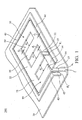
- FIG. 1 is a schematic perspective view of the planar antenna of an embodiment of the invention; and
- FIG. 2 is a schematic view of the mobile telecommunication device of an embodiment of the invention.
- Referring to FIG. 1, the
planar antenna 100 comprises aground area 10, a firstplane radiation member 20, a secondplane radiation member 30, and a thirdplane radiation member 40. The firstplane radiation member 20, secondplane radiation member 30, and thirdplane radiation member 40 are on the same plane. To simplify the drawings, only a part of theground area 10 is shown in FIG. 1. - The first
plane radiation member 20 opposes theground area 10 and is separated therefrom by a predetermined distance. The firstplane radiation member 20 is Π-shaped and provides a first resonant frequency. The firstplane radiation member 20 comprises afirst ground end 22, afeeding end 24, and anintermediate portion 21. Theintermediate portion 21 is disposed between thefirst ground end 22 and thefeeding end 24, or thefirst ground end 22 and feedingend 24 are respectively disposed on both sides of theintermediate portion 21. Thefirst ground end 22 is connected to a ground point g1 of theground area 10 via a firstground conducting element 23. Thefeeding end 24 is connected to afeeding conducting element 25. Thefeeding conducting element 25 passes through a through hole a1 of theground area 10 and is connected to a feeding point f, to input signals. - The second
plane radiation member 30 opposes theground area 10 and is separated therefrom by a predetermined distance. The secondplane radiation member 30 comprises a connectingportion 32, a firstfree end 34, and a secondfree end 36. Thefeeding end 24 andintermediate portion 21 of the firstplane radiation member 20 and the connectingportion 32 and firstfree end 34 of the secondplane radiation member 30 constitute a radiation path providing a second resonant frequency. Specifically, the second resonant frequency is less than the first resonant frequency. - Additionally, the connecting
portion 32 of the secondplane radiation member 30 is connected to theintermediate portion 21 of the firstplane radiation member 20. The firstfree end 34 extends to one side of the firstplane radiation member 20 and is separated from thefirst ground end 22 and feedingend 24 by a first gap d1. Thefirst ground end 22 of the firstplane radiation member 20 and the connectingportion 32 and firstfree end 34 of the secondplane radiation member 30 constitute anenclosed area 50. The secondfree end 36 of the secondplane radiation member 30 diverges from the firstfree end 34, extends into theenclosed area 50, and is parallel to thefirst ground end 22 and feedingend 24. Accordingly, thefirst ground end 22 is between the feedingend 24 and the secondfree end 36. Additionally, the front of secondfree end 36 is separated from the connectingportion 32 by a second gap d2. - The third
plane radiation member 40 opposes theground area 10 and is separated therefrom by a predetermined distance. The thirdplane radiation member 40 provides a third resonant frequency differing from the first and second resonant frequencies. Additionally, the thirdplane radiation member 40 comprises a second ground end 42 and a thirdfree end 44. The second ground end 42 is connected to a ground point g2 of theground area 10 via a secondground conducting element 43. The thirdfree end 44 surrounds the firstplane radiation member 20 and secondplane radiation member 30 and is separated therefrom by a third gap d3. - In the
planar antenna 100, the thirdplane radiation member 40 provides a parasitic path and thereby serves as a resonator. The bandwidth of the firstplane radiation member 20 is thus enlarged. Accordingly, the third resonant frequency can be greater or less than the first resonant frequency. - In a preferred embodiment of the
planar antenna 100, the length of the first, second, and third plane radiation members may approximately be one-fourth of the wavelength at the corresponding resonant point. The first resonant frequency is between 1710 MHz and 1880 MHz (DCS 1800). The second resonant frequency is between 880 MHz and 960 MHz (EGSM 800). The second resonant frequency is between 880 MHz and 960 MHz (PCS 1900). Thus, theplanar antenna 100 can be applied to conventional mobile telecommunication systems providing multi-band operation. - FIG. 2 is a schematic view of the
mobile telecommunication device 200 of the invention. Themobile telecommunication device 200 can be, for example, a cellular phone. - As shown in FIG. 2, the
mobile telecommunication device 200 comprises ahousing 110, anantenna base 120, and aplanar antenna 100. Thehousing 110 comprises anupper case 111 and aback cover 112. Theantenna base 120 is disposed between theupper case 111 and theback cover 112 and comprises aback surface 124, afront surface 122, and aground area 10. Theback surface 124 faces theback cover 112, and thefront surface 122 faces theupper case 111. Specifically, theground area 10 is also disposed in theplanar antenna 100. The firstplane radiation member 20, secondplane radiation member 30, and thirdplane radiation member 40 of theplanar antenna 100 is capable of emitting electromagnetic waves of different frequency bands. - The first
plane radiation member 20 and secondplane radiation member 30 constitute a structure with two opposing inverted-F elements. Thefirst ground end 22 is separated from the feedingend 24 by a fourth gap d4. The secondfree end 36 is separated from thefirst ground end 22 by a fifth gap d5. The secondfree end 36 is separated from an intermediate section between the connectingportion 32 and the firstfree end 34 by a sixth gap d6. Specifically, when theplanar antenna 100 is applied to different cellular phones, the resonant frequencies and gain distribution of theplanar antenna 100 deviate due to different antenna bases, ground areas, and housings. The width of the fourth gap d4 (conduction area between thefirst ground end 22 and the feeding end 24) can be adjusted to alter the point and bandwidth of the first resonant frequency, or the position of the secondfree end 36 in the enclosed area 50 (widths of the fifth gap d5 and sixth gap d6) can be adjusted to alter the point and bandwidth of the second resonant frequency. - Moreover, the third
plane radiation member 40 of theplanar antenna 100 serves as a resonator. The bandwidth of the first resonant frequency can be adjusted by adjusting the width of the thirdplane radiation member 40 or third gap d3. Accordingly, theplanar antenna 100 can cover three frequency bands of EGSM, GSM 1800, and . GSM 1900, enabling triple-band transmission. - Furthermore, when the profile of the
planar antenna 100 remains unchanged, the sizes and widths of the firstplane radiation member 20, secondplane radiation member 30, and thirdplane radiation member 40 and gaps therebetween can be adequately adjusted such that theplanar antenna 100 can provide other frequency bands and be applied to other telecommunication devices providing dual-band operation, such as IEEE 802.11.b and 802.11.a. - While the invention has been described by way of example and in terms of preferred embodiment, it is to be understood that the invention is not limited thereto. To the contrary, it is intended to cover various modifications and similar arrangements (as would be apparent to those skilled in the art). Therefore, the scope of the appended claims should be accorded the broadest interpretation so as to encompass all such modifications and similar arrangements.
Claims (28)
- A planar antenna, comprising:a ground area;a first plane radiation member opposing the ground area and providing a first resonant frequency, wherein the first plane radiation member comprises a first ground end, a feeding end, and an intermediate portion disposed between the first ground end and the feeding end, the first ground end is connected to the ground area, and the feeding end inputs signals;a second plane radiation member opposing the ground area and comprising a connecting portion and a first free end, wherein the connecting portion is connected to the intermediate portion, the first free end extends to one side of the first plane radiation member and is separated from the first ground end and feeding end by a first gap, and the feeding end, intermediate portion, connecting portion and first free end constitute a radiation path providing a second resonant frequency; anda third plane radiation member opposing the ground area and providing a third resonant frequency differing from the first and second resonant frequencies, wherein the third plane radiation member comprises a second ground end and a third free end, the second ground end is connected to the ground area, and the third free end surrounds the first and second plane radiation members and is separated from the first and second plane radiation members by a third gap.
- The planar antenna as claimed in claim 1, wherein the second plane radiation member further comprises a second free end diverging from the first free end to the connecting portion and separated from the connecting portion by a second gap.
- The planar antenna as claimed in claim 2, wherein the first plane radiation member, connecting portion and first free end constitute an enclosed area, and the second free end diverging from the first free end extends into the enclosed area.
- The planar antenna as claimed in claim 2, wherein the first plane radiation member is Π-shaped, and the first ground end and feeding end are respectively on both sides of the intermediate portion.
- The planar antenna as claimed in claim 4, wherein one side of the first plane radiation member, the connecting portion and first free end constitute an enclosed area, and the second free end diverging from the first free end extends into the enclosed area.
- The planar antenna as claimed in claim 5, wherein the first ground end is disposed between the feeding end and the second free end.
- The planar antenna as claimed in claim 5, wherein the second free end extending toward the connecting portion is separated from the connecting portion by a second gap.
- The planar antenna as claimed in claim 1, wherein the first, second and third plane radiation members are on the same plane.
- The planar antenna as claimed in claim 1, wherein the third resonant frequency exceeds the first resonant frequency, and the first resonant frequency exceeds the second resonant frequency.
- The planar antenna as claimed in claim 1, wherein the first resonant frequency is between 1710 MHz and 1880 MHz.
- The planar antenna as claimed in claim 1, wherein the second resonant frequency is between 880 MHz and 960 MHz.
- The planar antenna as claimed in claim 1, wherein the third resonant frequency is between 1850 MHz and 1990 MHz.
- A planar antenna, comprising:a ground area;a first plane radiation member opposing the ground area and providing a first resonant frequency, wherein the first plane radiation member comprises a first ground end, a feeding end, and an intermediate portion disposed between the first ground end and the feeding end, the first ground end is connected to the ground area, and the feeding end inputs signals; anda second plane radiation member opposing the ground area and comprising a connecting portion, a first free end and a second free end, wherein the connecting portion is connected to the intermediate portion, the first free end extends to one side of the first plane radiation member and is separated from the first ground end and feeding end by a first gap, the second free end diverges from the first free end to the connecting portion and is separated from the connecting portion by a second gap, and the feeding end, intermediate portion, connecting portion and first free end constitute a, radiation path providing a second resonant frequency.
- A planar antenna, comprising:a ground area;a first plane radiation member opposing the ground area and providing a first resonant frequency, wherein the first plane radiation member is Π-shaped and comprises a first ground end, a feeding end, and an intermediate portion disposed between the first ground end and the feeding end, the first ground end is connected to the ground area, and the feeding end inputs signals; anda second plane radiation member opposing the ground area and comprising a connecting portion and a first free end, wherein the connecting portion is connected to the intermediate portion, the first free end extends to one side of the first plane radiation member and is separated from the first ground end and feeding end by a first gap, and the feeding end, intermediate portion, connecting portion and first free end constitute a radiation path providing a second resonant frequency.
- A mobile telecommunication device, comprising:a housing comprising an upper case and a back cover;an antenna base disposed between the upper case and the back cover and comprising a back surface, a front surface, and a ground area, wherein the back surface faces the back cover, and the front surface faces the upper case; anda planar antenna comprising:a first plane radiation member opposing the ground area and providing a first resonant frequency, wherein the first plane radiation member comprises a first ground end, a feeding end, and an intermediate portion disposed between the first ground end and the feeding end, the first ground end is connected to the ground area, and the feeding end inputs signals;a second plane radiation member opposing the ground area and comprising a connecting portion and a first free end, wherein the connecting portion is connected to the intermediate portion, the first free end extends to one side of the first plane radiation member and is separated from the first ground end and feeding end by a first gap, and the feeding end, intermediate portion, connecting portion and first free end constitute a radiation path providing a second resonant frequency; anda third plane radiation member opposing the ground area and providing a third resonant frequency differing from the first and second resonant frequencies, wherein the third plane radiation member comprises a second ground end and a third free end, the second ground end is connected to the ground area, and the third free end surrounds the first and second plane radiation members and is separated from the first and second plane radiation members by a third gap.
- The mobile telecommunication device as claimed in claim 15, wherein the second plane radiation member further comprises a second free end diverging from the first free end to the connecting portion and separated from the connecting portion by a second gap.
- The mobile telecommunication device as claimed in claim 16, wherein the first plane radiation member, connecting portion and first free end constitute an enclosed area, and the second free end diverging from the first free end extends into the enclosed area.
- The mobile telecommunication device as claimed in claim 16, wherein the first plane radiation member is Π-shaped, and the first ground end and feeding end are respectively on two sides of the intermediate portion.
- The mobile telecommunication device as claimed in claim 18, wherein one side of the first plane radiation member, the connecting portion and first free end constitute an enclosed area, and the second free end diverging from the first free end extends into the enclosed area.
- The mobile telecommunication device as claimed in claim 19, wherein the first ground end is disposed between the feeding end and the second free end.
- The mobile telecommunication device as claimed in claim 19, wherein the second free end extending toward the connecting portion is separated from the connecting portion by a second gap.
- The mobile telecommunication device as claimed in claim 15, wherein the first, second and third plane radiation members are on the same plane.
- The mobile telecommunication device as claimed in claim 15, wherein the third resonant frequency exceeds the first resonant frequency.
- The mobile telecommunication device as claimed in claim 15, wherein the first resonant frequency is between 1710 MHz and 1880 MHz.
- The mobile telecommunication device as claimed in claim 15, wherein the second resonant frequency is between 880 MHz and 960 MHz.
- The mobile telecommunication device as claimed in claim 15, wherein the third resonant frequency is between 1850 MHz and 1990 MHz.
- A mobile telecommunication device, comprising:a housing comprising an upper case and a back cover;an antenna base disposed between the upper case and the back cover and comprising a back surface, a front surface, and a ground area, wherein the back surface faces the back cover, the front surface faces the upper case, and the ground area is disposed on the front surface; anda planar antenna comprising:a first plane radiation member opposing the ground area and providing a first resonant frequency, wherein the first plane radiation member comprises a first ground end, a feeding end, and an intermediate portion disposed between the first ground end and the feeding end, the first ground end is connected to the ground area, and the feeding end inputs signals; anda second plane radiation member opposing the ground area and comprising a connecting portion, a first free end and a second free end, wherein the connecting portion is connected to the intermediate portion, the first free end extends to one side of the first plane radiation member and is separated from the first ground end and feeding end by a first gap, the second free end diverges from the first free end to the connecting portion and is separated from the connecting portion by a second gap, and the feeding end, intermediate portion, connecting portion and first free end constitute a radiation path providing a second resonant frequency.
- A mobile telecommunication device, comprising:a housing comprising an upper case and a back cover;an antenna base disposed between the upper case and the back cover and comprising a back surface, a front surface, and a ground area, wherein the back surface faces the back cover, and the front surface faces the upper case; anda planar antenna comprising:a first plane radiation member opposing the ground area and providing a first resonant frequency, wherein the first plane radiation member is Π -shaped and comprises a first ground end, a feeding end, and an intermediate portion disposed between the first ground end and the feeding end, the first ground end is connected to the ground area, and the feeding end inputs signals; anda second plane radiation member opposing the ground area and comprising a connecting portion and a first free end, wherein the connecting portion is connected to the intermediate portion, the first free end extends to one side of the first plane radiation member and is separated from the first ground end and feeding end by a first gap, and the feeding end, intermediate portion, connecting portion and first free end constitute a radiation path providing a second resonant frequency.
Applications Claiming Priority (1)
| Application Number | Priority Date | Filing Date | Title |
|---|---|---|---|
| CNB2004100826357A CN100544117C (en) | 2004-09-22 | 2004-09-22 | Device for mobile communication and plane antenna structure thereof |
Publications (2)
| Publication Number | Publication Date |
|---|---|
| EP1641077A1 true EP1641077A1 (en) | 2006-03-29 |
| EP1641077B1 EP1641077B1 (en) | 2015-08-19 |
Family
ID=35033648
Family Applications (1)
| Application Number | Title | Priority Date | Filing Date |
|---|---|---|---|
| EP05019902.5A Active EP1641077B1 (en) | 2004-09-22 | 2005-09-13 | Mobile telecommunication device and planar antenna therefor |
Country Status (2)
| Country | Link |
|---|---|
| EP (1) | EP1641077B1 (en) |
| CN (1) | CN100544117C (en) |
Cited By (4)
| Publication number | Priority date | Publication date | Assignee | Title |
|---|---|---|---|---|
| WO2008001167A1 (en) * | 2006-06-27 | 2008-01-03 | Nokia Corporation | Multiband multimode compact antenna system |
| WO2009091323A1 (en) * | 2008-01-18 | 2009-07-23 | Laird Technologies Ab | Antenna device and portable radio communication device comprising such an antenna device |
| WO2012160413A1 (en) * | 2011-05-23 | 2012-11-29 | Nokia Corporation | Apparatus and methods for wireless communication |
| US8994596B2 (en) | 2011-08-04 | 2015-03-31 | Arcadyan Technology Corporation | Multi-band antenna |
Families Citing this family (6)
| Publication number | Priority date | Publication date | Assignee | Title |
|---|---|---|---|---|
| CN101335375B (en) * | 2007-06-26 | 2013-01-16 | 启碁科技股份有限公司 | Three-frequency antenna and electronic apparatus applying the same |
| CN101442150B (en) * | 2007-11-23 | 2013-06-26 | 宏达国际电子股份有限公司 | Antenna suitable for thin type communication device |
| CN101651256B (en) * | 2008-08-13 | 2013-08-07 | 深圳富泰宏精密工业有限公司 | Tri-band antenna |
| CN102800924A (en) * | 2011-05-27 | 2012-11-28 | 神讯电脑(昆山)有限公司 | Triple-band antenna |
| CN102810722A (en) * | 2011-06-03 | 2012-12-05 | 启碁科技股份有限公司 | Broadband antenna |
| WO2018071388A1 (en) | 2016-10-12 | 2018-04-19 | Carrier Corporation | Through-hole inverted sheet metal antenna |
Citations (6)
| Publication number | Priority date | Publication date | Assignee | Title |
|---|---|---|---|---|
| US6343208B1 (en) * | 1998-12-16 | 2002-01-29 | Telefonaktiebolaget Lm Ericsson (Publ) | Printed multi-band patch antenna |
| WO2002078124A1 (en) * | 2001-03-22 | 2002-10-03 | Telefonaktiebolaget L M Ericsson (Publ) | Mobile communication device |
| WO2002078123A1 (en) * | 2001-03-23 | 2002-10-03 | Telefonaktiebolaget L M Ericsson (Publ) | A built-in, multi band, multi antenna system |
| US6476769B1 (en) * | 2001-09-19 | 2002-11-05 | Nokia Corporation | Internal multi-band antenna |
| EP1263079A1 (en) * | 2001-05-25 | 2002-12-04 | Nokia Corporation | Mobile phone antenna |
| WO2005043674A1 (en) * | 2003-10-31 | 2005-05-12 | Lk Products Oy | Multiband planar antenna |
-
2004
- 2004-09-22 CN CNB2004100826357A patent/CN100544117C/en not_active Expired - Lifetime
-
2005
- 2005-09-13 EP EP05019902.5A patent/EP1641077B1/en active Active
Patent Citations (6)
| Publication number | Priority date | Publication date | Assignee | Title |
|---|---|---|---|---|
| US6343208B1 (en) * | 1998-12-16 | 2002-01-29 | Telefonaktiebolaget Lm Ericsson (Publ) | Printed multi-band patch antenna |
| WO2002078124A1 (en) * | 2001-03-22 | 2002-10-03 | Telefonaktiebolaget L M Ericsson (Publ) | Mobile communication device |
| WO2002078123A1 (en) * | 2001-03-23 | 2002-10-03 | Telefonaktiebolaget L M Ericsson (Publ) | A built-in, multi band, multi antenna system |
| EP1263079A1 (en) * | 2001-05-25 | 2002-12-04 | Nokia Corporation | Mobile phone antenna |
| US6476769B1 (en) * | 2001-09-19 | 2002-11-05 | Nokia Corporation | Internal multi-band antenna |
| WO2005043674A1 (en) * | 2003-10-31 | 2005-05-12 | Lk Products Oy | Multiband planar antenna |
Cited By (6)
| Publication number | Priority date | Publication date | Assignee | Title |
|---|---|---|---|---|
| WO2008001167A1 (en) * | 2006-06-27 | 2008-01-03 | Nokia Corporation | Multiband multimode compact antenna system |
| KR101054713B1 (en) | 2006-06-27 | 2011-08-05 | 노키아 코포레이션 | Multiband Multimode Compact Antenna System |
| WO2009091323A1 (en) * | 2008-01-18 | 2009-07-23 | Laird Technologies Ab | Antenna device and portable radio communication device comprising such an antenna device |
| WO2012160413A1 (en) * | 2011-05-23 | 2012-11-29 | Nokia Corporation | Apparatus and methods for wireless communication |
| US9673525B2 (en) | 2011-05-23 | 2017-06-06 | Nokia Technologies Oy | Apparatus and methods for wireless communication |
| US8994596B2 (en) | 2011-08-04 | 2015-03-31 | Arcadyan Technology Corporation | Multi-band antenna |
Also Published As
| Publication number | Publication date |
|---|---|
| CN100544117C (en) | 2009-09-23 |
| EP1641077B1 (en) | 2015-08-19 |
| CN1753248A (en) | 2006-03-29 |
Similar Documents
| Publication | Publication Date | Title |
|---|---|---|
| US7161541B2 (en) | Mobile telecommunication device and planar antenna thereof | |
| EP1641077B1 (en) | Mobile telecommunication device and planar antenna therefor | |
| US6714162B1 (en) | Narrow width dual/tri ISM band PIFA for wireless applications | |
| US6552686B2 (en) | Internal multi-band antenna with improved radiation efficiency | |
| US6963308B2 (en) | Multiband antenna | |
| US6980154B2 (en) | Planar inverted F antennas including current nulls between feed and ground couplings and related communications devices | |
| KR100906510B1 (en) | Antenna arrangement | |
| US6573869B2 (en) | Multiband PIFA antenna for portable devices | |
| US6650294B2 (en) | Compact broadband antenna | |
| US7113133B2 (en) | Dual-band inverted-F antenna with a branch line shorting strip | |
| KR100993439B1 (en) | Antenna arrangement | |
| KR100967851B1 (en) | Tunable antenna for wireless communication terminals | |
| US7777684B2 (en) | Multi-band slot-strip antenna | |
| KR101054713B1 (en) | Multiband Multimode Compact Antenna System | |
| EP2648277A1 (en) | Penta-band and bluetooth internal antenna and mobile communication terminal thereof | |
| EP1453137A1 (en) | Antenna for portable radio | |
| US20050110692A1 (en) | Multiband planar built-in radio antenna with inverted-l main and parasitic radiators | |
| EP2610967A1 (en) | Communication device and antenna structure therein | |
| EP1345282B1 (en) | Multiband planar built-in radio antenna with inverted-l main and parasitic radiators | |
| US7616161B2 (en) | Portable wireless apparatus | |
| EP1973197B1 (en) | Multi-band slot-strip antenna | |
| KR100577188B1 (en) | Dual-band PIFA for ISM band | |
| CN112397888B (en) | Mobile device | |
| KR101589066B1 (en) | Antenna apparatus for portable terminal | |
| Kumar et al. | Modified quadratic koch shape slotted PIFA antenna for dual-band wireless system |
Legal Events
| Date | Code | Title | Description |
|---|---|---|---|
| PUAI | Public reference made under article 153(3) epc to a published international application that has entered the european phase |
Free format text: ORIGINAL CODE: 0009012 |
|
| AK | Designated contracting states |
Kind code of ref document: A1 Designated state(s): AT BE BG CH CY CZ DE DK EE ES FI FR GB GR HU IE IS IT LI LT LU LV MC NL PL PT RO SE SI SK TR |
|
| AX | Request for extension of the european patent |
Extension state: AL BA HR MK YU |
|
| 17P | Request for examination filed |
Effective date: 20060210 |
|
| AKX | Designation fees paid |
Designated state(s): DE FI FR GB SE |
|
| GRAP | Despatch of communication of intention to grant a patent |
Free format text: ORIGINAL CODE: EPIDOSNIGR1 |
|
| INTG | Intention to grant announced |
Effective date: 20150522 |
|
| RIC1 | Information provided on ipc code assigned before grant |
Ipc: H01Q 21/30 20060101AFI20150511BHEP Ipc: H01Q 5/378 20150101ALI20150511BHEP Ipc: H01Q 9/04 20060101ALI20150511BHEP Ipc: H01Q 5/00 20150101ALI20150511BHEP Ipc: H01Q 5/371 20150101ALI20150511BHEP Ipc: H01Q 1/24 20060101ALI20150511BHEP |
|
| GRAS | Grant fee paid |
Free format text: ORIGINAL CODE: EPIDOSNIGR3 |
|
| GRAA | (expected) grant |
Free format text: ORIGINAL CODE: 0009210 |
|
| AK | Designated contracting states |
Kind code of ref document: B1 Designated state(s): DE FI FR GB SE |
|
| REG | Reference to a national code |
Ref country code: GB Ref legal event code: FG4D |
|
| REG | Reference to a national code |
Ref country code: DE Ref legal event code: R096 Ref document number: 602005047271 Country of ref document: DE |
|
| PG25 | Lapsed in a contracting state [announced via postgrant information from national office to epo] |
Ref country code: FI Free format text: LAPSE BECAUSE OF FAILURE TO SUBMIT A TRANSLATION OF THE DESCRIPTION OR TO PAY THE FEE WITHIN THE PRESCRIBED TIME-LIMIT Effective date: 20150819 |
|
| PG25 | Lapsed in a contracting state [announced via postgrant information from national office to epo] |
Ref country code: SE Free format text: LAPSE BECAUSE OF FAILURE TO SUBMIT A TRANSLATION OF THE DESCRIPTION OR TO PAY THE FEE WITHIN THE PRESCRIBED TIME-LIMIT Effective date: 20150819 |
|
| REG | Reference to a national code |
Ref country code: DE Ref legal event code: R097 Ref document number: 602005047271 Country of ref document: DE |
|
| PLBE | No opposition filed within time limit |
Free format text: ORIGINAL CODE: 0009261 |
|
| STAA | Information on the status of an ep patent application or granted ep patent |
Free format text: STATUS: NO OPPOSITION FILED WITHIN TIME LIMIT |
|
| 26N | No opposition filed |
Effective date: 20160520 |
|
| REG | Reference to a national code |
Ref country code: FR Ref legal event code: PLFP Year of fee payment: 12 |
|
| REG | Reference to a national code |
Ref country code: FR Ref legal event code: PLFP Year of fee payment: 13 |
|
| REG | Reference to a national code |
Ref country code: FR Ref legal event code: PLFP Year of fee payment: 14 |
|
| P01 | Opt-out of the competence of the unified patent court (upc) registered |
Effective date: 20230428 |
|
| PGFP | Annual fee paid to national office [announced via postgrant information from national office to epo] |
Ref country code: GB Payment date: 20230703 Year of fee payment: 19 |
|
| PGFP | Annual fee paid to national office [announced via postgrant information from national office to epo] |
Ref country code: DE Payment date: 20230629 Year of fee payment: 19 |
|
| PGFP | Annual fee paid to national office [announced via postgrant information from national office to epo] |
Ref country code: FR Payment date: 20240620 Year of fee payment: 20 |