EP1641058B1 - Battery outer case and assembling method thereof - Google Patents
Battery outer case and assembling method thereof Download PDFInfo
- Publication number
- EP1641058B1 EP1641058B1 EP05020573A EP05020573A EP1641058B1 EP 1641058 B1 EP1641058 B1 EP 1641058B1 EP 05020573 A EP05020573 A EP 05020573A EP 05020573 A EP05020573 A EP 05020573A EP 1641058 B1 EP1641058 B1 EP 1641058B1
- Authority
- EP
- European Patent Office
- Prior art keywords
- main body
- container main
- metal container
- metal
- lid
- Prior art date
- Legal status (The legal status is an assumption and is not a legal conclusion. Google has not performed a legal analysis and makes no representation as to the accuracy of the status listed.)
- Expired - Lifetime
Links
Images


Classifications
-
- H—ELECTRICITY
- H01—ELECTRIC ELEMENTS
- H01M—PROCESSES OR MEANS, e.g. BATTERIES, FOR THE DIRECT CONVERSION OF CHEMICAL ENERGY INTO ELECTRICAL ENERGY
- H01M50/00—Constructional details or processes of manufacture of the non-active parts of electrochemical cells other than fuel cells, e.g. hybrid cells
- H01M50/20—Mountings; Secondary casings or frames; Racks, modules or packs; Suspension devices; Shock absorbers; Transport or carrying devices; Holders
-
- H—ELECTRICITY
- H01—ELECTRIC ELEMENTS
- H01M—PROCESSES OR MEANS, e.g. BATTERIES, FOR THE DIRECT CONVERSION OF CHEMICAL ENERGY INTO ELECTRICAL ENERGY
- H01M10/00—Secondary cells; Manufacture thereof
- H01M10/04—Construction or manufacture in general
- H01M10/0436—Small-sized flat cells or batteries for portable equipment
-
- H—ELECTRICITY
- H01—ELECTRIC ELEMENTS
- H01M—PROCESSES OR MEANS, e.g. BATTERIES, FOR THE DIRECT CONVERSION OF CHEMICAL ENERGY INTO ELECTRICAL ENERGY
- H01M10/00—Secondary cells; Manufacture thereof
- H01M10/04—Construction or manufacture in general
- H01M10/049—Processes for forming or storing electrodes in the battery container
-
- H—ELECTRICITY
- H01—ELECTRIC ELEMENTS
- H01M—PROCESSES OR MEANS, e.g. BATTERIES, FOR THE DIRECT CONVERSION OF CHEMICAL ENERGY INTO ELECTRICAL ENERGY
- H01M50/00—Constructional details or processes of manufacture of the non-active parts of electrochemical cells other than fuel cells, e.g. hybrid cells
- H01M50/10—Primary casings; Jackets or wrappings
-
- Y—GENERAL TAGGING OF NEW TECHNOLOGICAL DEVELOPMENTS; GENERAL TAGGING OF CROSS-SECTIONAL TECHNOLOGIES SPANNING OVER SEVERAL SECTIONS OF THE IPC; TECHNICAL SUBJECTS COVERED BY FORMER USPC CROSS-REFERENCE ART COLLECTIONS [XRACs] AND DIGESTS
- Y02—TECHNOLOGIES OR APPLICATIONS FOR MITIGATION OR ADAPTATION AGAINST CLIMATE CHANGE
- Y02E—REDUCTION OF GREENHOUSE GAS [GHG] EMISSIONS, RELATED TO ENERGY GENERATION, TRANSMISSION OR DISTRIBUTION
- Y02E60/00—Enabling technologies; Technologies with a potential or indirect contribution to GHG emissions mitigation
- Y02E60/10—Energy storage using batteries
-
- Y—GENERAL TAGGING OF NEW TECHNOLOGICAL DEVELOPMENTS; GENERAL TAGGING OF CROSS-SECTIONAL TECHNOLOGIES SPANNING OVER SEVERAL SECTIONS OF THE IPC; TECHNICAL SUBJECTS COVERED BY FORMER USPC CROSS-REFERENCE ART COLLECTIONS [XRACs] AND DIGESTS
- Y10—TECHNICAL SUBJECTS COVERED BY FORMER USPC
- Y10T—TECHNICAL SUBJECTS COVERED BY FORMER US CLASSIFICATION
- Y10T29/00—Metal working
- Y10T29/49—Method of mechanical manufacture
- Y10T29/49002—Electrical device making
- Y10T29/49108—Electric battery cell making
-
- Y—GENERAL TAGGING OF NEW TECHNOLOGICAL DEVELOPMENTS; GENERAL TAGGING OF CROSS-SECTIONAL TECHNOLOGIES SPANNING OVER SEVERAL SECTIONS OF THE IPC; TECHNICAL SUBJECTS COVERED BY FORMER USPC CROSS-REFERENCE ART COLLECTIONS [XRACs] AND DIGESTS
- Y10—TECHNICAL SUBJECTS COVERED BY FORMER USPC
- Y10T—TECHNICAL SUBJECTS COVERED BY FORMER US CLASSIFICATION
- Y10T29/00—Metal working
- Y10T29/49—Method of mechanical manufacture
- Y10T29/49002—Electrical device making
- Y10T29/49108—Electric battery cell making
- Y10T29/4911—Electric battery cell making including sealing
Definitions
- the present invention relates to a battery outer case that houses a flat battery pack such as, for example, a laminate cell battery, etc., composed of a plurality of thin batteries laminated one over another.
- a flat battery pack such as, for example, a laminate cell battery, etc., composed of a plurality of thin batteries laminated one over another.
- a battery outer case 100 shown in Fig. 4A includes a metal container main body 102 in which a flat battery pack 101 is housed therein, and a metal lid 103 that serves to close an opening formed in the metal container main body 102.
- An outwardly protruding connection flange 104 is formed at an open end of the metal container main body 102, and a connection flange 105, similarly protruding outwards, is formed on an end portion of the metal lid 103, with the respective connection flanges 104, 105 being superposed and coupled with each other by means of spot welding or caulking.
- a caulking technique there can be used eyelets, so-called TOX ( a registered trademark of TOX PRESSOTECHNIK Co., Ltd. ) joints, etc.
- a metal container main body 102 is formed at its open end with a joint piece 106 extended upwards therefrom for connection, and a metal lid 101 is also formed on its outer periphery with an upwardly extending joint piece 107, the joint pieces 106, 107 being superposed and coupled with each other by means of spot welding or caulking.
- a metal lid 103 is placed in abutment with a corresponding edge of a metal container main body 102 while eliminating the above-mentioned connection flanges and joint pieces, and abutment portions 108 of the metal lid 103 and the metal container main body 102 are joined with each other by laser welding (for example, Japanese patent application laid-open No. 2004-14125 ).
- Fig. 4E shows an example in which a metal container main body 102 and a metal lid 103 are coupled with each other by means of bolts 109.
- each bolt 109 has its bolt shaft portion 109a inserted into a bolt hole formed in the metal lid 103, and its bolt head 109b engaged with the metal lid 103, with an end of the bolt shaft portion 109a being threaded into a bottom plate portion 102a of the metal container main body 102.
- each bolt 109 projects from an upper surface of the metal lid 103, so the occupation space of the entire apparatus is accordingly increased by the height of each bolt head 109b, and at the same time, the entire weight thereof is also increased by the weight of all the bolts 109.
- a caulking structure used in a cylindrical battery or the like is employed, as shown in Fig. 4F .
- This caulking structure is such that a lid body 203 is inserted into the inner periphery of an open end portion of a metal container main body 201 through a ring-shaped gasket 202, and is then fixedly secured to the metal container main body 201 by caulking or bending the open end portion thereof inwardly.
- the gasket 202 is needed as an additional part, resulting in an increase in the number of required parts.
- US Patent No 6,451,476 B1 discloses a case for a secondary battery, which has a space in which an assembled battery unit including a positive electrode plate, a separator, and a negative electrode plate is accommodated, and sealing portions welded along the periphery of the space, wherein at least one notch is present in the sealing portions.
- the present invention has been made to solve the problems as referred to above, and has for its object to provide a battery outer case for a flat battery pack in which the length of protrusion of joint portions between a metal container main body and a metal lid can be reduced to achieve space saving, and which is free from the influence of heat and makes it unnecessary to employ additional or extra parts such as a gasket, etc.
- a battery outer case comprising: a metal container main body having at least one surface opened with a flat battery pack received therein; and a metal lid that serves to close an opening formed in the metal container main body; wherein the inside of the container is in communication with the outside thereof so as to have air permeability, and an open end periphery of the metal container main body and a lid end periphery of the metal lid are joined to each other by seaming.
- the flat battery pack comprises a laminate battery pack provided with an exterior member that is composed of a synthetic resin layer and a metal layer laminated one over the other.
- the metal container main body is provided with holes through which terminals connected to the flat battery pack inside the container are exposed.
- the metal container main body has a peripheral portion around each of the holes which is more rigid than the other portions thereof.
- a reinforcement bead is formed at a location near each of the holes in the metal container main body so as to provide high rigidity.
- the metal container main body has a turned back portion formed around each of the holes so as to provide high rigidity.
- the metal container main body and the metal lid have at least their inner surfaces coated with insulating layers, respectively.
- an assembling method for a battery outer case comprising the steps of: molding a metal container main body with holes formed beforehand in its body portion for exposing terminals connected to a flat battery pack; receiving the flat battery pack in the metal container main body while fitting the terminals into the holes; covering the metal container main body with a metal lid; and superposing an open end portion of the metal container main body and an end portion of the metal lid with each other thereby to join them to each other by double seaming.
- the length of protrusion of the seam portions from the metal container main body can be reduced as much as possible, so the metal container main body and the lid body can be joined to each other in a relatively small space.
- the present invention is optimal for the structure in which the flat battery pack is composed of laminate type batteries laminated one over another, as stated in the above-mentioned first preferred form of the invention.
- the laminate type batteries there is no influence of heat on the laminate type batteries, so it is possible to reduce the occupation space of the container itself as much as possible.
- the light-weight and small-size characteristics, which are major features of the laminate type batteries, are not disturbed or reduced.
- the metal container main body is provided with holes through which terminals connected to the flat battery pack are exposed, the flat battery pack can be smoothly received in the metal container main body.
- peripheral portions around the holes become liable to be deformed upon seaming, but such seaming can be performed without causing deformation by making the peripheral portions around the holes more rigid than the other portions, as stated in the above-mentioned third preferred form of the present invention, by reinforcing the peripheral portions around the holes by means of the reinforcement beads or the turned back portions as stated in the above-mentioned fourth or fifth preferred form of the present invention.
- the metal container main body and the metal lid by coating at least the inner surfaces of the metal container main body and the metal lid with the insulating layer, it is possible to provide electrical insulation against exposed tabs of the thin batteries. Moreover, since the thin batteries themselves are laminated, insulation becomes doubled, thus making it possible to improve insulation performance.
- the sections of the notched holes can be electrically insulated.
- Fig. 1 shows a battery outer case according to one embodiment of the present invention.
- the battery outer case generally designated at 1, includes a metal container main body 3 with an open upper surface and having a flat battery pack 2 housed or received therein, and a metal lid 5 that serves to close an opening 4 formed in the metal container main body 3, an open end periphery 6 of the metal container main body 3 and a lid end periphery 7 of the metal lid 5 being joined to each other by seaming.
- seam portions 8 are formed at the joint portions of the open end periphery 6 of the metal container main body 3 and the lid end periphery 7, respectively.
- the flat battery pack 2 is constructed as follows. That is, inside a battery exterior composed of a laminate film there are laminated or stacked a plurality of serially connected laminate type batteries 21 in the form of a plurality of rectangular-shaped thin batteries, each of which is formed by sealing power generation elements each composed of a plus and a minus electrode plate and a separator laminated one over another.
- the laminate type batteries 21 are assembled into a vertically flat hexahedral shape as a whole, and a plus terminal 22 and a minus terminal 23 are arranged at the opposite ends of a short side of the flat hexahedral body, the plus terminal 22 and the minus terminal 23 being covered with a pair of terminal insulation resin covers 24, 25.
- a voltage measuring connector 26 is arranged at a location between the plus terminal 22 and the minus terminal 23 for measuring the voltage of each of the laminate type batteries 21.
- the metal container main body 3 takes the shape of a thin box, and includes a body portion 31 of a polygonal cylindrical configuration which surrounds the flat battery pack 2, and a bottom plate portion 32 which closes a lower end of the body portion 31 and on which a lower surface of the flat battery pack 2 is placed.
- the cross-sectional shape of the body portion 31 is rectangular with rounded corners, conforming to the planar shape of the flat battery pack, and includes a first side wall 31 a and a second side wall 31 b on a short side, and a third side wall 31 c and a fourth side wall 31 d on a long side.
- the height of the body portion 31 is set to be substantially the same as the height of the flat battery pack 2.
- the metal lid 5 takes the form of a thin plate-shaped configuration, and the lid end portion 7 is formed into a rectangular configuration with rounded corners, conforming to the open end portion 6 of the body portion 31.
- a metal material with its surface covered with an electrically insulating resin is suitable as a material that constitutes the container main body 3 and the lid body 5.
- an aluminum sheet with its front and back side surfaces covered with a PET resin film is preferable.
- a 5052 AL material of a thickness of 0.5 mm is preferable, and it is also preferable that the PET resin film located on an inner side of the container be 20 microns, and that the PET resin film located on an outer side thereof be 20 microns.
- the first and second holes 91, 92 are in the form of U shapes, respectively, conforming to the configurations of the terminal insulation resin covers 24, 25 that cover the plus terminal 22 and the minus terminal 23, respectively, and includes two pairs of right and left side edge portions 91a, 91b; 92a, 92b extending linearly from the upper open end portion 6 of the first side wall 31 a toward its lower end corners near the bottom plate portion 32 in parallel with each other, and circular-arc shaped lower edge portions 91c, 91c each connecting between the lower ends of the corresponding side edge portions 91a, 91b; 92a, 92b.
- the third hole 93 is rectangular, and includes a pair of right and left side edge portions 93a, 93b extending linearly from the upper open end portion of the first side wall 31 a toward its lower end corners near the bottom plate portion 32 in parallel with each other, and a rectilinear lower edge portion 93c connecting between the lower ends of the side edge portions 93a, 93b.
- the lower edge portion 93c extends along the lower end corners.
- formed in the metal lid 5 is a fifth lid-side hole 95 continuously extending from the third notchedhole 93.
- the lid-side hole 95 takes the form of a rectangular configuration with the same width as that of the third hole 93, and extends a predetermined length from an end of the metal lid 5 in a direction perpendicular to the first side wall 31 a, so that the third hole 93 and the fifth hole 95 are combined with each other to form one hole.
- a fourth hole 94 is formed in the second side wall 31b at the central location thereof. This fourth hole 94 extends across a lower end corner of the second side wall 31b to enter the bottom plate portion 32 a predetermined length.
- Reinforcement beads 10 are formed on the first side wall 31 a around the peripheral portions of the first hole 91, the second hole 92 and the third hole 93 formed therein, and on the second side wall 92 around the peripheral portion of the fourth hole 94 formed therein.
- these first and second side walls 91, 92 with the reinforcement beads 10 become more rigid than the other portions without any hole formed therein ( e.g., the third and fourth side walls 31c, 31d on the long side in this example ).
- Each of the reinforcement beads 10 is a convex row or bar of a predetermined width that protrudes from the surface of the container toward the outside thereof or a concave row or bar recessed or depressed from the surface of the container toward the outside thereof, and is of such a structure that it extends vertically in a line over the entire height of the first and second side walls 31a, 31b.
- first hole 91 and the second notched hole 92 of the first side wall 31a are located adjacent to corners of high rigidity, a plurality of (e.g., three in the illustrated example ) reinforcement beads 10 are arranged at predetermined peripheral intervals in a region between the first hole 91 and the third hole 93 as well as in a region between the third hole 93 and the second hole 92.
- reinforcement beads 10 arranged in the immediate vicinity of the first hole 91, the second hole 92 and the third hole 93 are adjoined to the side edges of the notched holes 91, 92.
- the reinforcement beads 10 on the second side wall 31 b are provided in pluralities ( e.g., two at each side in the illustrated example ) in a right and a left region of the fourth central hole 94. Those among the plurality of reinforcement beads 10 which are arranged adjacent to the fourth hole 94 are arranged in close proximity of the fourth hole 94.
- the battery outer case of the above construction is assembled as follows.
- the metal container main body 3 is first molded which has the first, second, third and fourth holes 91, 92, 93 and 94 formed in the first and second side walls 31 a, 31 b of the body portion 31 thereof, and the flat battery pack 2 is received in the metal container main body 3 thus molded.
- the insulating resin portions 24, 25 of the plus terminal 22 and the minus terminal 23 are fitted into the first and second holes 91, 92, respectively.
- the metal lid 5 is placed onto the metal container main body 3 in such a manner that the lid-side hole 95 is aligned with the third hole 93, and then the open end portion of the metal container main body 3 and the lid end portion of the metal lid 5 are superposed with each other and double seamed to form the seam portions 8, thus completing the coupling therebetween.
- a seam curl portion 71 formed at the lid end portion 7 of the metal lid 5 and a seam flange portion 61 formed at the open end portion 6 of the metal container main body 3 are superposed with each other and seam joined to each other by pressing a seam roll 300 against these portions 71, 61 from a side thereof, but the first side wall 31a and the second side wall 31b of the metal container main body 3 are subject to an axial compression load F and a bending moment M from the seam flange portion 61. Since the peripheral portions of the metal container main body 3 having the notches formed therein are low in rigidity, they can be easily buckling deformed under the action of the compression load F and the bending moment M, as shown in Fig.
- the dimensions of the seam portions 8 are such that they have a width a of at most 3 mm and a height b of at most 3 mm, as shown in Fig. 2D , and hence the occupation space can be reduced as compared with conventional welding or caulking. In addition, there is caused no thermal deformation of the container and no thermal damage to the flat battery pack 2, as will be in the case of welding.
- first and second holes 91, 92 are formed beforehand, so that when the flat battery pack 2 is received in the metal container main body 3, the terminal insulation resin covers 24, 25 of the plus terminal 22 and the minus terminal 23 can be fitted into the first and second holes 91, 92 from above. As a result, the flat battery pack 2 can be received smoothly in the metal container main body 3 from above the opening portion 4 thereof.
- the inside of the container in which the flat battery pack 2 is received is in communication with the outside thereof through the first through fourth holes 91, 92, 93 and 94 or through the seam portions 8 so as to have air permeability. Accordingly, even if gas is generated in the thin batteries that constitute the flat battery pack and the gas thus generated flows out to the outside of the thin batteries, the gas can be escaped to the outside of the container.
- the seam portions 8 will be of a structure having air permeability if no compound is interposed therebetween.
- the peripheral portions around the first and second holes 91, 92 and the third hole 93 are bent or turned back to form upright ribs 11 in the form of turned back portions for improved rigidity without forming any reinforcement bead.
- first and second holes 91, 92 are arranged at their one side adjacent to corners and have high rigidity at that side, so upright ribs 11 are formed at their side edges 91b, 92a opposing the third hole 93.
- the third hole 93 is formed at its opposite side edges with upright ribs 11.
- Fig. 3B through 3D show a further embodiment of the present invention.
- the inner surface of the metal container main body 3 is coated with an insulating layer, and the upright ribs 11 in the form of the turned back portions are formed to extend over the right and left side edge portions 91a, 91b; 92a, 92b and the circular-arc shaped lower edge portions 91c, 92c, whereby electrical insulation of the plus terminal 22 and the minus terminal 23 as well as structural reinforcement can be made.
- the plus terminal 22 and the minus terminal 23 can be electrically insulated without the metal material of the metal container being exposed to the sections of the first and second holes 91, 92, so the terminal insulation resin covers 24, 25 become unnecessary.
- the body portion 31 and the bottom plate portion 32 may be formed separately from each other.
Landscapes
- Chemical & Material Sciences (AREA)
- Chemical Kinetics & Catalysis (AREA)
- Electrochemistry (AREA)
- General Chemical & Material Sciences (AREA)
- Engineering & Computer Science (AREA)
- Manufacturing & Machinery (AREA)
- Sealing Battery Cases Or Jackets (AREA)
Abstract
Description
- The present invention relates to a battery outer case that houses a flat battery pack such as, for example, a laminate cell battery, etc., composed of a plurality of thin batteries laminated one over another.
- As a battery outer case in which this kind of flat battery pack is housed, there can be considered such a one as shown in
Figs. 4A through 4F . - Specifically, a battery
outer case 100 shown inFig. 4A includes a metal containermain body 102 in which aflat battery pack 101 is housed therein, and ametal lid 103 that serves to close an opening formed in the metal containermain body 102. An outwardly protruding connection flange 104 is formed at an open end of the metal containermain body 102, and aconnection flange 105, similarly protruding outwards, is formed on an end portion of themetal lid 103, with therespective connection flanges 104, 105 being superposed and coupled with each other by means of spot welding or caulking. As such a caulking technique, there can be used eyelets, so-called TOX ( a registered trademark of TOX PRESSOTECHNIK Co., Ltd. ) joints, etc. - In
Fig. 4B , a metal containermain body 102 is formed at its open end with ajoint piece 106 extended upwards therefrom for connection, and ametal lid 101 is also formed on its outer periphery with an upwardly extendingjoint piece 107, thejoint pieces - In the jointing or coupling techniques as shown in
Fig. 4A and Fig. 4B , however, there is the following problem. That is, in any case of spot welding and caulking joint, it is necessary for thejoint pieces connection flanges 104, 105 to have their widths X1, Y1 of at least 7 to 10 mm as a welding margin or a caulking margin, and hence the occupation space thereof becomes accordingly large. - Thus, as shown in
Fig. 4C and Fig. 4D , it is considered that an edge of ametal lid 103 is placed in abutment with a corresponding edge of a metal containermain body 102 while eliminating the above-mentioned connection flanges and joint pieces, andabutment portions 108 of themetal lid 103 and the metal containermain body 102 are joined with each other by laser welding ( for example,Japanese patent application laid-open No. 2004-14125 - In such a case of abutment joint or connection, however, spatter generated upon welding can be easily dispersed into the inside of the container, and heat can also be transmitted to the inside of the container, so the
flat battery pack 101 is liable to be damaged. In particular, in the case of a thin battery with its exterior being formed of a laminate film, the laminate layer can be damaged to induce a reduction in electrical insulation. -
Fig. 4E shows an example in which a metal containermain body 102 and ametal lid 103 are coupled with each other by means ofbolts 109. In this example, eachbolt 109 has itsbolt shaft portion 109a inserted into a bolt hole formed in themetal lid 103, and itsbolt head 109b engaged with themetal lid 103, with an end of thebolt shaft portion 109a being threaded into abottom plate portion 102a of the metal containermain body 102. - In this case, however, there arises another problem. That is, the
bolt head 109b of eachbolt 109 projects from an upper surface of themetal lid 103, so the occupation space of the entire apparatus is accordingly increased by the height of eachbolt head 109b, and at the same time, the entire weight thereof is also increased by the weight of all thebolts 109. - In addition, it can be further considered that a caulking structure used in a cylindrical battery or the like is employed, as shown in
Fig. 4F . This caulking structure is such that alid body 203 is inserted into the inner periphery of an open end portion of a metal containermain body 201 through a ring-shapedgasket 202, and is then fixedly secured to the metal containermain body 201 by caulking or bending the open end portion thereof inwardly. - In the case of such a caulking structure, however, the
gasket 202 is needed as an additional part, resulting in an increase in the number of required parts. -
US Patent No 6,451,476 B1 discloses a case for a secondary battery, which has a space in which an assembled battery unit including a positive electrode plate, a separator, and a negative electrode plate is accommodated, and sealing portions welded along the periphery of the space, wherein at least one notch is present in the sealing portions. - Accordingly, the present invention has been made to solve the problems as referred to above, and has for its object to provide a battery outer case for a flat battery pack in which the length of protrusion of joint portions between a metal container main body and a metal lid can be reduced to achieve space saving, and which is free from the influence of heat and makes it unnecessary to employ additional or extra parts such as a gasket, etc.
- In order to achieve the above object, according to one aspect of the present invention, there is provided a battery outer case comprising: a metal container main body having at least one surface opened with a flat battery pack received therein; and a metal lid that serves to close an opening formed in the metal container main body; wherein the inside of the container is in communication with the outside thereof so as to have air permeability, and an open end periphery of the metal container main body and a lid end periphery of the metal lid are joined to each other by seaming.
- In a first preferred form of the present invention, the flat battery pack comprises a laminate battery pack provided with an exterior member that is composed of a synthetic resin layer and a metal layer laminated one over the other.
- In a second preferred form of the present invention, the metal container main body is provided with holes through which terminals connected to the flat battery pack inside the container are exposed.
- In a third preferred form of the present invention, the metal container main body has a peripheral portion around each of the holes which is more rigid than the other portions thereof.
- In a fourth preferred form of the present invention, a reinforcement bead is formed at a location near each of the holes in the metal container main body so as to provide high rigidity.
- In a fifth preferred form of the present invention, the metal container main body has a turned back portion formed around each of the holes so as to provide high rigidity.
- In a sixth preferred form of the present invention, the metal container main body and the metal lid have at least their inner surfaces coated with insulating layers, respectively.
- According to another aspect of the present invention, there is provided an assembling method for a battery outer case comprising the steps of: molding a metal container main body with holes formed beforehand in its body portion for exposing terminals connected to a flat battery pack; receiving the flat battery pack in the metal container main body while fitting the terminals into the holes; covering the metal container main body with a metal lid; and superposing an open end portion of the metal container main body and an end portion of the metal lid with each other thereby to join them to each other by double seaming.
- According to the above-mentioned first aspect of the present invention, since seam portions are constructed to be crushed toward the metal container main body, the length of protrusion of the seam portions from the metal container main body can be reduced as much as possible, so the metal container main body and the lid body can be joined to each other in a relatively small space.
- In addition, since the seam joint between the metal container main body and the lid body can be done by seaming, there is no fear that the flat battery pack might be thermally damaged or the container might be thermally deformed, as would be caused by welding.
- Moreover, since it is constructed such that the seam joint between the metal container main body and the metal lid is carried out by making use of part of themselves, any additional parts are not required to this end. Further, since it is also constructed such that the inside of the container is in communication with the outside thereof to have air permeability, even if gas generated in the thin batteries constituting the flat battery pack flows out to the outside of the thin batteries, the gas can be escaped to the outside of the container.
- The present invention is optimal for the structure in which the flat battery pack is composed of laminate type batteries laminated one over another, as stated in the above-mentioned first preferred form of the invention. Thus, there is no influence of heat on the laminate type batteries, so it is possible to reduce the occupation space of the container itself as much as possible. As a result, the light-weight and small-size characteristics, which are major features of the laminate type batteries, are not disturbed or reduced.
- According to the above-mentioned second preferred form of the present invention, since the metal container main body is provided with holes through which terminals connected to the flat battery pack are exposed, the flat battery pack can be smoothly received in the metal container main body.
- In addition, in the case of the presence of the holes, the peripheral portions around the holes become liable to be deformed upon seaming, but such seaming can be performed without causing deformation by making the peripheral portions around the holes more rigid than the other portions, as stated in the above-mentioned third preferred form of the present invention, by reinforcing the peripheral portions around the holes by means of the reinforcement beads or the turned back portions as stated in the above-mentioned fourth or fifth preferred form of the present invention.
- According to the above-mentioned sixth preferred form of the present invention, by coating at least the inner surfaces of the metal container main body and the metal lid with the insulating layer, it is possible to provide electrical insulation against exposed tabs of the thin batteries. Moreover, since the thin batteries themselves are laminated, insulation becomes doubled, thus making it possible to improve insulation performance.
- Further, in case where the turned back portions are provided at the ends of the holes, the sections of the notched holes can be electrically insulated.
- The above and other objects, features and advantages of the present invention will become more readily apparent to those skilled in the art from the following detailed description of preferred embodiments of the present invention taken in conjunction with the accompanying drawings.
-
-
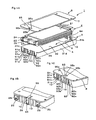
Fig. 1A is an exploded perspective view of a battery outer case according to one embodiment of the present invention. -
Fig. 1B is a perspective view of essential portions of the battery outer case ofFig. 1A when assembled. -
Fig. 1C is a perspective view of the battery outer case with an internal battery inFig. 1B being removed. -
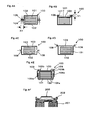
Figs. 2A through 2C are views for explaining the function of a reinforcement bead in a seaming step. -
Fig. 2D is a view showing how large seam portions are. -
Fig. 3A is a perspective view of essential portions of a battery outer case according to another embodiment of the present invention with a thin battery assembly therein being permitted. -
Fig. 3B is a perspective view of essential portions of a battery outer case according to a further embodiment of the present invention with a thin battery assembly therein being permitted. -
Fig. 3C is an enlarged perspective view of a notched portion. -
Fig. 3D is a perspective view showing a state in which a terminal protrudes from a notched hole ofFig. 3C . -
Fig. 4A through Fig. 4F show conventional battery outer cases, respectively, in whichFig. 4A is a cross sectional view schematically showing a container with joint flanges for spot welding or caulking;Fig. 4B is a cross sectional view schematically showing a container with joint pieces for spot welding or caulking;Fig. 4C and Fig. 4D are cross sectional views schematically showing the containers and lids ofFig. 4A and Fig. 4B which are joined to each other by laser welding, respectively, with the joint flanges and the joint pieces being eliminated;Fig. 4E is a cross sectional view schematically showing a container with a lid bolted thereto; andFig. 4F is a cross sectional view of essential portions of a cylindrical battery showing a caulking structure of a lid. - Now, preferred embodiments of the present invention will be described below while referring to the accompanying drawings.
-
Fig. 1 shows a battery outer case according to one embodiment of the present invention. - The battery outer case, generally designated at 1, includes a metal container
main body 3 with an open upper surface and having aflat battery pack 2 housed or received therein, and ametal lid 5 that serves to close an opening 4 formed in the metal containermain body 3, anopen end periphery 6 of the metal containermain body 3 and a lid end periphery 7 of themetal lid 5 being joined to each other by seaming. To this end,seam portions 8 are formed at the joint portions of theopen end periphery 6 of the metal containermain body 3 and the lid end periphery 7, respectively. - The
flat battery pack 2 is constructed as follows. That is, inside a battery exterior composed of a laminate film there are laminated or stacked a plurality of serially connectedlaminate type batteries 21 in the form of a plurality of rectangular-shaped thin batteries, each of which is formed by sealing power generation elements each composed of a plus and a minus electrode plate and a separator laminated one over another. Thus, thelaminate type batteries 21 are assembled into a vertically flat hexahedral shape as a whole, and aplus terminal 22 and aminus terminal 23 are arranged at the opposite ends of a short side of the flat hexahedral body, theplus terminal 22 and theminus terminal 23 being covered with a pair of terminal insulation resin covers 24, 25. In addition, avoltage measuring connector 26 is arranged at a location between theplus terminal 22 and theminus terminal 23 for measuring the voltage of each of thelaminate type batteries 21. - The metal container
main body 3 takes the shape of a thin box, and includes abody portion 31 of a polygonal cylindrical configuration which surrounds theflat battery pack 2, and abottom plate portion 32 which closes a lower end of thebody portion 31 and on which a lower surface of theflat battery pack 2 is placed. The cross-sectional shape of thebody portion 31 is rectangular with rounded corners, conforming to the planar shape of the flat battery pack, and includes afirst side wall 31 a and asecond side wall 31 b on a short side, and athird side wall 31 c and afourth side wall 31 d on a long side. The height of thebody portion 31 is set to be substantially the same as the height of theflat battery pack 2. - The
metal lid 5 takes the form of a thin plate-shaped configuration, and the lid end portion 7 is formed into a rectangular configuration with rounded corners, conforming to theopen end portion 6 of thebody portion 31. - A metal material with its surface covered with an electrically insulating resin ( insulating layer ) is suitable as a material that constitutes the container
main body 3 and thelid body 5. For instance, an aluminum sheet with its front and back side surfaces covered with a PET resin film is preferable. For such an aluminum sheet, a 5052 AL material of a thickness of 0.5 mm is preferable, and it is also preferable that the PET resin film located on an inner side of the container be 20 microns, and that the PET resin film located on an outer side thereof be 20 microns. - A first and a
second hole plus terminal 22 and theminus terminal 23 connected with theflat battery pack 2 in the container are exposed to the outside, are formed in thefirst side wall 31a of the metal containermain body 3 at the left and right sides thereof at a predetermined distance apart from each other. In addition, a third notchedhole 93, from which thevoltage measuring connector 26 of each of thelaminate type batteries 21 constituting theflat battery pack 2 is exposed to the outside, is formed in thefirst side wall 31 a of the metal containermain body 3 at a location intermediate between the first andsecond holes - The first and
second holes plus terminal 22 and theminus terminal 23, respectively, and includes two pairs of right and leftside edge portions open end portion 6 of thefirst side wall 31 a toward its lower end corners near thebottom plate portion 32 in parallel with each other, and circular-arc shapedlower edge portions side edge portions - The
third hole 93 is rectangular, and includes a pair of right and leftside edge portions first side wall 31 a toward its lower end corners near thebottom plate portion 32 in parallel with each other, and a rectilinearlower edge portion 93c connecting between the lower ends of theside edge portions lower edge portion 93c extends along the lower end corners. Also, formed in themetal lid 5 is a fifth lid-side hole 95 continuously extending from thethird notchedhole 93. The lid-side hole 95 takes the form of a rectangular configuration with the same width as that of thethird hole 93, and extends a predetermined length from an end of themetal lid 5 in a direction perpendicular to thefirst side wall 31 a, so that thethird hole 93 and thefifth hole 95 are combined with each other to form one hole. - A
fourth hole 94 is formed in thesecond side wall 31b at the central location thereof. Thisfourth hole 94 extends across a lower end corner of thesecond side wall 31b to enter the bottom plate portion 32 a predetermined length. -
Reinforcement beads 10 are formed on thefirst side wall 31 a around the peripheral portions of thefirst hole 91, thesecond hole 92 and thethird hole 93 formed therein, and on thesecond side wall 92 around the peripheral portion of thefourth hole 94 formed therein. Thus, these first andsecond side walls reinforcement beads 10 become more rigid than the other portions without any hole formed therein ( e.g., the third andfourth side walls - Each of the
reinforcement beads 10 is a convex row or bar of a predetermined width that protrudes from the surface of the container toward the outside thereof or a concave row or bar recessed or depressed from the surface of the container toward the outside thereof, and is of such a structure that it extends vertically in a line over the entire height of the first andsecond side walls - Since the
first hole 91 and the second notchedhole 92 of thefirst side wall 31a are located adjacent to corners of high rigidity, a plurality of ( e.g., three in the illustrated example )reinforcement beads 10 are arranged at predetermined peripheral intervals in a region between thefirst hole 91 and thethird hole 93 as well as in a region between thethird hole 93 and thesecond hole 92. In particular,reinforcement beads 10 arranged in the immediate vicinity of thefirst hole 91, thesecond hole 92 and thethird hole 93 are adjoined to the side edges of the notchedholes - The
reinforcement beads 10 on thesecond side wall 31 b are provided in pluralities ( e.g., two at each side in the illustrated example ) in a right and a left region of the fourthcentral hole 94. Those among the plurality ofreinforcement beads 10 which are arranged adjacent to thefourth hole 94 are arranged in close proximity of thefourth hole 94. - The battery outer case of the above construction is assembled as follows.
- That is, the metal container
main body 3 is first molded which has the first, second, third andfourth holes second side walls body portion 31 thereof, and theflat battery pack 2 is received in the metal containermain body 3 thus molded. Upon receiving of theflat battery pack 2, the insulatingresin portions plus terminal 22 and theminus terminal 23 are fitted into the first andsecond holes - Next, the
metal lid 5 is placed onto the metal containermain body 3 in such a manner that the lid-side hole 95 is aligned with thethird hole 93, and then the open end portion of the metal containermain body 3 and the lid end portion of themetal lid 5 are superposed with each other and double seamed to form theseam portions 8, thus completing the coupling therebetween. - As shown in
Fig. 2A and 2B , aseam curl portion 71 formed at the lid end portion 7 of themetal lid 5 and aseam flange portion 61 formed at theopen end portion 6 of the metal containermain body 3 are superposed with each other and seam joined to each other by pressing aseam roll 300 against theseportions first side wall 31a and thesecond side wall 31b of the metal containermain body 3 are subject to an axial compression load F and a bending moment M from theseam flange portion 61. Since the peripheral portions of the metal containermain body 3 having the notches formed therein are low in rigidity, they can be easily buckling deformed under the action of the compression load F and the bending moment M, as shown inFig. 2C , if in the absence of thereinforcement beads 10. In this embodiment, however, the flexural rigidity of the notched peripheral portions is raised by thereinforcement beads 10, so the notched peripheral portions of the firstside wall section 31 a and the secondside wall section 31b can be prevented from deformation. - The dimensions of the
seam portions 8 are such that they have a width a of at most 3 mm and a height b of at most 3 mm, as shown inFig. 2D , and hence the occupation space can be reduced as compared with conventional welding or caulking. In addition, there is caused no thermal deformation of the container and no thermal damage to theflat battery pack 2, as will be in the case of welding. - Further, the first and
second holes flat battery pack 2 is received in the metal containermain body 3, the terminal insulation resin covers 24, 25 of theplus terminal 22 and theminus terminal 23 can be fitted into the first andsecond holes flat battery pack 2 can be received smoothly in the metal containermain body 3 from above the opening portion 4 thereof. - Moreover, in this embodiment, it is constructed such that the inside of the container in which the
flat battery pack 2 is received is in communication with the outside thereof through the first throughfourth holes seam portions 8 so as to have air permeability. Accordingly, even if gas is generated in the thin batteries that constitute the flat battery pack and the gas thus generated flows out to the outside of the thin batteries, the gas can be escaped to the outside of the container. Theseam portions 8 will be of a structure having air permeability if no compound is interposed therebetween. - Next, another embodiment of the present invention will be described while referring to
Figs. 3A through 3D . In the following description, only differences from the above-mentioned embodiment will be explained with the same components being identified by the same symbols while omitting an explanation thereof. - In
Fig. 3A , the peripheral portions around the first andsecond holes third hole 93 are bent or turned back to formupright ribs 11 in the form of turned back portions for improved rigidity without forming any reinforcement bead. - That is, the first and
second holes upright ribs 11 are formed at theirside edges third hole 93. On the other hand, thethird hole 93 is formed at its opposite side edges withupright ribs 11. Theseupright ribs 11 are constructed in such a manner that they are bent or turned back in a direction to protrude outside of the container to form a U-shaped configuration, with the inner surface side of the container being exposed to the surface thereof. - Further,
Fig. 3B through 3D show a further embodiment of the present invention. - In this embodiment, for the first and
second holes terminals main body 3 is coated with an insulating layer, and theupright ribs 11 in the form of the turned back portions are formed to extend over the right and leftside edge portions lower edge portions plus terminal 22 and theminus terminal 23 as well as structural reinforcement can be made. With such a construction, theplus terminal 22 and theminus terminal 23 can be electrically insulated without the metal material of the metal container being exposed to the sections of the first andsecond holes - Although in the above embodiments, there has been shown an example of the metal container
main body 3 in which thebody portion 31 and thebottom plate portion 32 are integrally molded with each other, thebody portion 31 and thebottom plate portion 32 may be formed separately from each other. - While the invention has been described in terms of preferred embodiments, those skilled in the art will recognize that the invention can be practiced with modifications within the spirit and scope of the appended claims.
Claims (7)
- A battery outer case (1) comprising:a metal container main body (3) having at least one surface opened, the metal container main body (3) containing a flat battery pack (2); anda metal lid (5) that serves to close an opening formed in said metal container main body (3);wherein the inside of said container is in communication with the outside thereof so as to have air permeability, and an open end periphery of said metal container main body (3) and a lid end periphery of said metal lid (5) are joined to each other by seaming; andsaid metal container main body (3) is provided with holes (91, 92) through which terminals (22, 23) connected to said flat battery pack (2) inside said container are exposed, said holes extending from the open end portion of said metal container main body (3).
- The battery outer case (1) as set forth in claim 1, wherein said flat battery pack (2) is composed of laminate type batteries (21) laminated one over another.
- The battery outer case (1) as set forth in claim 2, wherein said metal container main body (3) has a peripheral portion around each of said holes (91, 92) which is more rigid than the other portions thereof.
- The battery outer case (1) as set forth in claim 3, wherein a reinforcement bead (10) is formed at a location near each of said holes (91, 92) in said metal container main body (3) so as to provide high rigidity.
- The battery outer case (1) as set forth in claim 3, wherein said metal container main body (3) has a turned back portion formed around each of said holes (91, 92) so as to provide high rigidity.
- The battery outer case (1) as set forth in any one of claims 1 through 5, wherein said metal container main body (3) and said metal lid (5) have at least their inner surfaces coated with insulating layers, respectively.
- An assembling method for a battery outer case (1) comprising the steps of:molding a metal container main body (3) with holes (91, 92) formed in its body portion for exposing terminals (22, 23) connected to a flat battery pack (2), said holes (91, 92) extending from an open end portion of said metal container main body (3);receiving said flat battery pack (2) with said metal container main body (3) while fitting said terminals (22, 23) into said holes (91, 92);covering said metal container main body (3) with a metal lid (5); andsuperposing the open end portion of said metal container main body (3) and an end portion of said metal lid (5) with each other to join them to each other by seaming.
Applications Claiming Priority (1)
| Application Number | Priority Date | Filing Date | Title |
|---|---|---|---|
| JP2004276250A JP4786159B2 (en) | 2004-09-22 | 2004-09-22 | Battery storage container and assembly method thereof |
Publications (2)
| Publication Number | Publication Date |
|---|---|
| EP1641058A1 EP1641058A1 (en) | 2006-03-29 |
| EP1641058B1 true EP1641058B1 (en) | 2009-04-15 |
Family
ID=35519903
Family Applications (1)
| Application Number | Title | Priority Date | Filing Date |
|---|---|---|---|
| EP05020573A Expired - Lifetime EP1641058B1 (en) | 2004-09-22 | 2005-09-21 | Battery outer case and assembling method thereof |
Country Status (7)
| Country | Link |
|---|---|
| US (2) | US7910241B2 (en) |
| EP (1) | EP1641058B1 (en) |
| JP (1) | JP4786159B2 (en) |
| KR (1) | KR101217609B1 (en) |
| CN (1) | CN100517804C (en) |
| AT (1) | ATE429038T1 (en) |
| DE (1) | DE602005013873D1 (en) |
Families Citing this family (33)
| Publication number | Priority date | Publication date | Assignee | Title |
|---|---|---|---|---|
| JP5070697B2 (en) | 2005-12-19 | 2012-11-14 | 日産自動車株式会社 | Battery module |
| JP4722015B2 (en) | 2005-12-29 | 2011-07-13 | 三星エスディアイ株式会社 | Polymer battery pack |
| KR100770097B1 (en) | 2006-08-07 | 2007-10-24 | 삼성에스디아이 주식회사 | Polymer battery pack |
| JP5277523B2 (en) * | 2006-06-27 | 2013-08-28 | 日産自動車株式会社 | Assembled battery and manufacturing method of assembled battery |
| JP4251204B2 (en) | 2006-08-31 | 2009-04-08 | 日産自動車株式会社 | Battery module |
| JP2008091205A (en) * | 2006-10-02 | 2008-04-17 | Nissan Motor Co Ltd | Battery module |
| JP5082054B2 (en) * | 2006-12-08 | 2012-11-28 | 日産自動車株式会社 | Battery module, battery case, battery case winding device and method |
| JP5236210B2 (en) | 2007-05-10 | 2013-07-17 | カルソニックカンセイ株式会社 | Battery module structure of the battery |
| KR100917750B1 (en) * | 2007-09-17 | 2009-09-15 | 삼성에스디아이 주식회사 | Battery pack |
| JP5338203B2 (en) * | 2008-08-28 | 2013-11-13 | 日産自動車株式会社 | Battery storage case |
| US9029007B2 (en) * | 2009-04-03 | 2015-05-12 | Samsung Sdi Co., Ltd. | Rechargeable battery including first and second metallic plates coupled together and a cap assembly including an insulator |
| DE102009035489A1 (en) * | 2009-07-31 | 2011-02-03 | Daimler Ag | Single cell for a battery |
| BR112012031165A2 (en) | 2010-06-09 | 2016-11-01 | Nissan Motor | battery module |
| JP2012089415A (en) * | 2010-10-21 | 2012-05-10 | Sharp Corp | Secondary battery and battery pack |
| JP5216073B2 (en) | 2010-11-26 | 2013-06-19 | 東洋製罐株式会社 | Container, lid and container winding method |
| JP2012174451A (en) * | 2011-02-21 | 2012-09-10 | Sharp Corp | Secondary battery |
| JP6269865B2 (en) * | 2011-05-27 | 2018-01-31 | 株式会社村田製作所 | Battery unit, battery module, power storage system, electronic device, power system, and electric vehicle |
| JP2013033688A (en) * | 2011-08-03 | 2013-02-14 | Sharp Corp | Secondary battery |
| JP5869435B2 (en) | 2012-06-27 | 2016-02-24 | トヨタ自動車株式会社 | Square battery and method for manufacturing square battery |
| JP5480335B2 (en) * | 2012-06-28 | 2014-04-23 | トヨタ自動車株式会社 | Square battery and method for manufacturing square battery |
| US9099692B2 (en) * | 2012-11-07 | 2015-08-04 | Hyundai Motor Company | Rechargeable battery |
| DE102014208555A1 (en) * | 2014-05-07 | 2015-11-12 | Siemens Aktiengesellschaft | Process for producing a latent heat storage |
| CN104953182B (en) * | 2015-05-25 | 2018-03-30 | 安徽天康(集团)股份有限公司 | The method of solution party's shaped steel shell power lithium-ion battery side potting problem |
| US10777784B2 (en) | 2015-10-16 | 2020-09-15 | Robert Bosch Battery Systems Llc | Deep format pouch for battery cell |
| DE102016225175A1 (en) * | 2016-12-15 | 2018-06-21 | Robert Bosch Gmbh | Serving for a battery module |
| KR102164632B1 (en) * | 2017-07-31 | 2020-10-12 | 주식회사 엘지화학 | Battery module, battery pack and energy storage system comprising the same |
| US10601003B2 (en) | 2017-10-30 | 2020-03-24 | Lg Chem, Ltd. | Battery module and method of assembling the battery module |
| DE102018212722A1 (en) * | 2018-07-31 | 2020-02-06 | Robert Bosch Gmbh | Electrical energy storage device and / or vehicle |
| CN113632298B (en) * | 2019-03-27 | 2023-12-05 | 松下新能源株式会社 | Battery |
| US20230170559A1 (en) * | 2020-08-11 | 2023-06-01 | Lg Energy Solution, Ltd. | Button-type secondary battery and method for manufacturing the same |
| JP7208200B2 (en) * | 2020-09-09 | 2023-01-18 | プライムプラネットエナジー&ソリューションズ株式会社 | A battery, a battery case provided for the battery, and a battery case member for constructing the battery case |
| JP2022055562A (en) * | 2020-09-29 | 2022-04-08 | Tdk株式会社 | Button-type electrochemical element |
| CN217086752U (en) * | 2022-06-16 | 2022-07-29 | 宁德时代新能源科技股份有限公司 | Battery box, battery and power consumption device |
Family Cites Families (23)
| Publication number | Priority date | Publication date | Assignee | Title |
|---|---|---|---|---|
| GB356271A (en) | 1930-06-06 | 1931-09-07 | Nat Carbon Co Inc | Dry cells |
| US2185216A (en) * | 1935-09-14 | 1940-01-02 | Crown Can Company | Metal container |
| US3745035A (en) * | 1970-12-03 | 1973-07-10 | Rheem Mfg Co | Container lining method |
| US4642922A (en) * | 1985-12-06 | 1987-02-17 | D.M.D.S.R.L. | Removable steam iron sole plate |
| JPH01281665A (en) | 1988-05-09 | 1989-11-13 | Japan Storage Battery Co Ltd | Sealed type lead-acid battery |
| JP3427216B2 (en) * | 1993-02-09 | 2003-07-14 | 日本電池株式会社 | Prismatic battery |
| DE69529476T2 (en) * | 1994-12-01 | 2003-11-27 | Micron Technology, Inc. | METHOD FOR PRODUCING BUTTON BATTERIES, BUTTON BATTERY INSULATION AND SEALING RING |
| JPH1140115A (en) * | 1997-07-18 | 1999-02-12 | Japan Storage Battery Co Ltd | Battery and battery pack using this battery |
| US6410186B1 (en) * | 1998-08-21 | 2002-06-25 | Eveready Battery Company, Inc. | Battery construction having double seam cover closure |
| JP2000090913A (en) * | 1998-09-11 | 2000-03-31 | Japan Storage Battery Co Ltd | Battery |
| JP3527858B2 (en) * | 1999-01-04 | 2004-05-17 | 三菱電機株式会社 | Battery |
| KR100319108B1 (en) * | 1999-04-16 | 2001-12-29 | 김순택 | Case of the secondary battery |
| EP1071147A1 (en) * | 1999-07-19 | 2001-01-24 | Toshiba Battery Co., Ltd. | Battery pack |
| JP2001126678A (en) * | 1999-10-28 | 2001-05-11 | Hitachi Maxell Ltd | Stacked polymer electrolyte battery |
| DE20020392U1 (en) * | 2000-12-01 | 2001-04-26 | TRW Automotive Electronics & Components GmbH & Co. KG, 78315 Radolfzell | Housing for an electronic monitoring device on vehicle parts |
| JP4694033B2 (en) * | 2001-05-10 | 2011-06-01 | 昭和アルミニウム缶株式会社 | Case for electrical equipment |
| JP2003272588A (en) * | 2002-03-15 | 2003-09-26 | Nissan Motor Co Ltd | Battery module |
| JP4214450B2 (en) | 2002-06-03 | 2009-01-28 | 日本電気株式会社 | module |
| JP3687632B2 (en) * | 2002-06-26 | 2005-08-24 | 日産自動車株式会社 | Thin battery |
| JP3624903B2 (en) * | 2002-07-04 | 2005-03-02 | 日産自動車株式会社 | Module battery |
| KR20040017094A (en) * | 2002-08-20 | 2004-02-26 | 삼성에스디아이 주식회사 | Pouch type secondary battery with safty vent |
| US6926541B2 (en) * | 2002-08-30 | 2005-08-09 | Yazaki Corporation | Mounting structure of electric junction box |
| JP4635425B2 (en) * | 2003-09-24 | 2011-02-23 | 凸版印刷株式会社 | Lithium-ion battery exterior |
-
2004
- 2004-09-22 JP JP2004276250A patent/JP4786159B2/en not_active Expired - Lifetime
-
2005
- 2005-09-13 US US11/225,828 patent/US7910241B2/en active Active
- 2005-09-21 AT AT05020573T patent/ATE429038T1/en not_active IP Right Cessation
- 2005-09-21 EP EP05020573A patent/EP1641058B1/en not_active Expired - Lifetime
- 2005-09-21 CN CNB2005101035348A patent/CN100517804C/en not_active Expired - Lifetime
- 2005-09-21 DE DE602005013873T patent/DE602005013873D1/en not_active Expired - Lifetime
- 2005-09-22 KR KR1020050087934A patent/KR101217609B1/en not_active Expired - Fee Related
-
2010
- 2010-12-02 US US12/958,736 patent/US8747490B2/en not_active Expired - Lifetime
Also Published As
| Publication number | Publication date |
|---|---|
| US20110067229A1 (en) | 2011-03-24 |
| US20060121344A1 (en) | 2006-06-08 |
| JP4786159B2 (en) | 2011-10-05 |
| US8747490B2 (en) | 2014-06-10 |
| CN100517804C (en) | 2009-07-22 |
| KR101217609B1 (en) | 2013-01-02 |
| DE602005013873D1 (en) | 2009-05-28 |
| US7910241B2 (en) | 2011-03-22 |
| EP1641058A1 (en) | 2006-03-29 |
| JP2006092884A (en) | 2006-04-06 |
| CN1767227A (en) | 2006-05-03 |
| ATE429038T1 (en) | 2009-05-15 |
| KR20060051509A (en) | 2006-05-19 |
Similar Documents
| Publication | Publication Date | Title |
|---|---|---|
| EP1641058B1 (en) | Battery outer case and assembling method thereof | |
| US9905826B2 (en) | Electric storage device and rechargeable battery | |
| US8173293B2 (en) | Pouch type battery pack | |
| US10971705B2 (en) | Pouch for secondary battery and die for forming the same | |
| EP3046158B1 (en) | Rechargeable battery and pack of the same | |
| JP4757508B2 (en) | Electrical device assembly | |
| EP2299511A1 (en) | Rechargeable battery and battery module | |
| US20020064708A1 (en) | Prismatic battery module and method for manufacturing the same | |
| US20250023146A1 (en) | Battery casing and battery | |
| KR20220057441A (en) | Power storage cell and method of manufacturing same | |
| EP3086382B1 (en) | Rechargeable battery | |
| US12002998B2 (en) | Secondary battery | |
| JP5825155B2 (en) | Case for power storage device, power storage device, secondary battery, and moving body | |
| EP4254642A1 (en) | Power storage device | |
| JP2021086675A (en) | Pressure control valve structure and power storage module | |
| CN203260661U (en) | Sealed battery | |
| JP7103033B2 (en) | Power storage module and manufacturing method of power storage module | |
| US20250286182A1 (en) | Battery | |
| US20240413490A1 (en) | Secondary battery | |
| JP7550151B2 (en) | Prismatic secondary battery | |
| EP4700933A1 (en) | Secondary battery | |
| JP2012119620A (en) | Storage cell | |
| JP2025140066A (en) | Power storage device | |
| JP2025167945A (en) | secondary battery | |
| KR20240158170A (en) | Battery cell and method for producing such a battery cell |
Legal Events
| Date | Code | Title | Description |
|---|---|---|---|
| PUAI | Public reference made under article 153(3) epc to a published international application that has entered the european phase |
Free format text: ORIGINAL CODE: 0009012 |
|
| AK | Designated contracting states |
Kind code of ref document: A1 Designated state(s): AT BE BG CH CY CZ DE DK EE ES FI FR GB GR HU IE IS IT LI LT LU LV MC NL PL PT RO SE SI SK TR |
|
| AX | Request for extension of the european patent |
Extension state: AL BA HR MK YU |
|
| RIN1 | Information on inventor provided before grant (corrected) |
Inventor name: ETSUO, OOGAMI Inventor name: TSUKADA, KATSUHIKOC/O TOYO SEIKAN KAISHA, LTD. Inventor name: SEIJIROU, YAJIMA Inventor name: TERUO, SEGAWA Inventor name: RYUICHI, AMAGAI |
|
| 17P | Request for examination filed |
Effective date: 20060822 |
|
| RIN1 | Information on inventor provided before grant (corrected) |
Inventor name: TERUO, SEGAWA Inventor name: SEIJIROU, YAJIMA Inventor name: RYUICHI, AMAGAI Inventor name: ETSUO, OOGAMI Inventor name: TSUKADA, KAZUHIKOC/O TOYO SEIKAN KAISHA, LTD. |
|
| AKX | Designation fees paid |
Designated state(s): AT BE BG CH CY CZ DE DK EE ES FI FR GB GR HU IE IS IT LI LT LU LV MC NL PL PT RO SE SI SK TR |
|
| 17Q | First examination report despatched |
Effective date: 20070126 |
|
| GRAP | Despatch of communication of intention to grant a patent |
Free format text: ORIGINAL CODE: EPIDOSNIGR1 |
|
| GRAP | Despatch of communication of intention to grant a patent |
Free format text: ORIGINAL CODE: EPIDOSNIGR1 |
|
| GRAS | Grant fee paid |
Free format text: ORIGINAL CODE: EPIDOSNIGR3 |
|
| GRAA | (expected) grant |
Free format text: ORIGINAL CODE: 0009210 |
|
| AK | Designated contracting states |
Kind code of ref document: B1 Designated state(s): AT BE BG CH CY CZ DE DK EE ES FI FR GB GR HU IE IS IT LI LT LU LV MC NL PL PT RO SE SI SK TR |
|
| REG | Reference to a national code |
Ref country code: CH Ref legal event code: EP Ref country code: GB Ref legal event code: FG4D |
|
| REG | Reference to a national code |
Ref country code: IE Ref legal event code: FG4D |
|
| REF | Corresponds to: |
Ref document number: 602005013873 Country of ref document: DE Date of ref document: 20090528 Kind code of ref document: P |
|
| NLV1 | Nl: lapsed or annulled due to failure to fulfill the requirements of art. 29p and 29m of the patents act | ||
| PG25 | Lapsed in a contracting state [announced via postgrant information from national office to epo] |
Ref country code: FI Free format text: LAPSE BECAUSE OF FAILURE TO SUBMIT A TRANSLATION OF THE DESCRIPTION OR TO PAY THE FEE WITHIN THE PRESCRIBED TIME-LIMIT Effective date: 20090415 Ref country code: PT Free format text: LAPSE BECAUSE OF FAILURE TO SUBMIT A TRANSLATION OF THE DESCRIPTION OR TO PAY THE FEE WITHIN THE PRESCRIBED TIME-LIMIT Effective date: 20090915 Ref country code: ES Free format text: LAPSE BECAUSE OF FAILURE TO SUBMIT A TRANSLATION OF THE DESCRIPTION OR TO PAY THE FEE WITHIN THE PRESCRIBED TIME-LIMIT Effective date: 20090726 Ref country code: AT Free format text: LAPSE BECAUSE OF FAILURE TO SUBMIT A TRANSLATION OF THE DESCRIPTION OR TO PAY THE FEE WITHIN THE PRESCRIBED TIME-LIMIT Effective date: 20090415 Ref country code: LT Free format text: LAPSE BECAUSE OF FAILURE TO SUBMIT A TRANSLATION OF THE DESCRIPTION OR TO PAY THE FEE WITHIN THE PRESCRIBED TIME-LIMIT Effective date: 20090415 |
|
| PG25 | Lapsed in a contracting state [announced via postgrant information from national office to epo] |
Ref country code: PL Free format text: LAPSE BECAUSE OF FAILURE TO SUBMIT A TRANSLATION OF THE DESCRIPTION OR TO PAY THE FEE WITHIN THE PRESCRIBED TIME-LIMIT Effective date: 20090415 Ref country code: NL Free format text: LAPSE BECAUSE OF FAILURE TO SUBMIT A TRANSLATION OF THE DESCRIPTION OR TO PAY THE FEE WITHIN THE PRESCRIBED TIME-LIMIT Effective date: 20090415 Ref country code: SE Free format text: LAPSE BECAUSE OF FAILURE TO SUBMIT A TRANSLATION OF THE DESCRIPTION OR TO PAY THE FEE WITHIN THE PRESCRIBED TIME-LIMIT Effective date: 20090715 Ref country code: LV Free format text: LAPSE BECAUSE OF FAILURE TO SUBMIT A TRANSLATION OF THE DESCRIPTION OR TO PAY THE FEE WITHIN THE PRESCRIBED TIME-LIMIT Effective date: 20090415 Ref country code: SI Free format text: LAPSE BECAUSE OF FAILURE TO SUBMIT A TRANSLATION OF THE DESCRIPTION OR TO PAY THE FEE WITHIN THE PRESCRIBED TIME-LIMIT Effective date: 20090415 Ref country code: IS Free format text: LAPSE BECAUSE OF FAILURE TO SUBMIT A TRANSLATION OF THE DESCRIPTION OR TO PAY THE FEE WITHIN THE PRESCRIBED TIME-LIMIT Effective date: 20090815 |
|
| PG25 | Lapsed in a contracting state [announced via postgrant information from national office to epo] |
Ref country code: EE Free format text: LAPSE BECAUSE OF FAILURE TO SUBMIT A TRANSLATION OF THE DESCRIPTION OR TO PAY THE FEE WITHIN THE PRESCRIBED TIME-LIMIT Effective date: 20090415 Ref country code: RO Free format text: LAPSE BECAUSE OF FAILURE TO SUBMIT A TRANSLATION OF THE DESCRIPTION OR TO PAY THE FEE WITHIN THE PRESCRIBED TIME-LIMIT Effective date: 20090415 Ref country code: CZ Free format text: LAPSE BECAUSE OF FAILURE TO SUBMIT A TRANSLATION OF THE DESCRIPTION OR TO PAY THE FEE WITHIN THE PRESCRIBED TIME-LIMIT Effective date: 20090415 Ref country code: DK Free format text: LAPSE BECAUSE OF FAILURE TO SUBMIT A TRANSLATION OF THE DESCRIPTION OR TO PAY THE FEE WITHIN THE PRESCRIBED TIME-LIMIT Effective date: 20090415 |
|
| PLBE | No opposition filed within time limit |
Free format text: ORIGINAL CODE: 0009261 |
|
| STAA | Information on the status of an ep patent application or granted ep patent |
Free format text: STATUS: NO OPPOSITION FILED WITHIN TIME LIMIT |
|
| PG25 | Lapsed in a contracting state [announced via postgrant information from national office to epo] |
Ref country code: BE Free format text: LAPSE BECAUSE OF FAILURE TO SUBMIT A TRANSLATION OF THE DESCRIPTION OR TO PAY THE FEE WITHIN THE PRESCRIBED TIME-LIMIT Effective date: 20090415 Ref country code: SK Free format text: LAPSE BECAUSE OF FAILURE TO SUBMIT A TRANSLATION OF THE DESCRIPTION OR TO PAY THE FEE WITHIN THE PRESCRIBED TIME-LIMIT Effective date: 20090415 |
|
| 26N | No opposition filed |
Effective date: 20100118 |
|
| PG25 | Lapsed in a contracting state [announced via postgrant information from national office to epo] |
Ref country code: BG Free format text: LAPSE BECAUSE OF FAILURE TO SUBMIT A TRANSLATION OF THE DESCRIPTION OR TO PAY THE FEE WITHIN THE PRESCRIBED TIME-LIMIT Effective date: 20090715 |
|
| PG25 | Lapsed in a contracting state [announced via postgrant information from national office to epo] |
Ref country code: MC Free format text: LAPSE BECAUSE OF NON-PAYMENT OF DUE FEES Effective date: 20090930 |
|
| REG | Reference to a national code |
Ref country code: CH Ref legal event code: PL |
|
| PG25 | Lapsed in a contracting state [announced via postgrant information from national office to epo] |
Ref country code: IE Free format text: LAPSE BECAUSE OF NON-PAYMENT OF DUE FEES Effective date: 20090921 |
|
| PG25 | Lapsed in a contracting state [announced via postgrant information from national office to epo] |
Ref country code: CH Free format text: LAPSE BECAUSE OF NON-PAYMENT OF DUE FEES Effective date: 20090930 Ref country code: GR Free format text: LAPSE BECAUSE OF FAILURE TO SUBMIT A TRANSLATION OF THE DESCRIPTION OR TO PAY THE FEE WITHIN THE PRESCRIBED TIME-LIMIT Effective date: 20090716 Ref country code: LI Free format text: LAPSE BECAUSE OF NON-PAYMENT OF DUE FEES Effective date: 20090930 |
|
| PG25 | Lapsed in a contracting state [announced via postgrant information from national office to epo] |
Ref country code: IT Free format text: LAPSE BECAUSE OF FAILURE TO SUBMIT A TRANSLATION OF THE DESCRIPTION OR TO PAY THE FEE WITHIN THE PRESCRIBED TIME-LIMIT Effective date: 20090415 |
|
| PG25 | Lapsed in a contracting state [announced via postgrant information from national office to epo] |
Ref country code: LU Free format text: LAPSE BECAUSE OF NON-PAYMENT OF DUE FEES Effective date: 20090921 |
|
| PG25 | Lapsed in a contracting state [announced via postgrant information from national office to epo] |
Ref country code: HU Free format text: LAPSE BECAUSE OF FAILURE TO SUBMIT A TRANSLATION OF THE DESCRIPTION OR TO PAY THE FEE WITHIN THE PRESCRIBED TIME-LIMIT Effective date: 20091016 |
|
| PG25 | Lapsed in a contracting state [announced via postgrant information from national office to epo] |
Ref country code: TR Free format text: LAPSE BECAUSE OF FAILURE TO SUBMIT A TRANSLATION OF THE DESCRIPTION OR TO PAY THE FEE WITHIN THE PRESCRIBED TIME-LIMIT Effective date: 20090415 |
|
| PG25 | Lapsed in a contracting state [announced via postgrant information from national office to epo] |
Ref country code: CY Free format text: LAPSE BECAUSE OF FAILURE TO SUBMIT A TRANSLATION OF THE DESCRIPTION OR TO PAY THE FEE WITHIN THE PRESCRIBED TIME-LIMIT Effective date: 20090415 |
|
| REG | Reference to a national code |
Ref country code: FR Ref legal event code: PLFP Year of fee payment: 12 |
|
| REG | Reference to a national code |
Ref country code: FR Ref legal event code: PLFP Year of fee payment: 13 |
|
| REG | Reference to a national code |
Ref country code: FR Ref legal event code: PLFP Year of fee payment: 14 |
|
| REG | Reference to a national code |
Ref country code: DE Ref legal event code: R082 Ref document number: 602005013873 Country of ref document: DE Representative=s name: ISARPATENT - PATENT- UND RECHTSANWAELTE BEHNIS, DE Ref country code: DE Ref legal event code: R081 Ref document number: 602005013873 Country of ref document: DE Owner name: NISSAN MOTOR CO., LTD., YOKOHAMA-SHI, JP Free format text: FORMER OWNERS: NISSAN MOTOR CO., LTD., YOKOHAMA-SHI, KANAGAWA-KEN, JP; TOYO SEIKAN KAISHA, LTD., TOKIO/TOKYO, JP Ref country code: DE Ref legal event code: R081 Ref document number: 602005013873 Country of ref document: DE Owner name: TOYO SEIKAN GROUP HOLDINGS, LTD., TOKYO, JP Free format text: FORMER OWNERS: NISSAN MOTOR CO., LTD., YOKOHAMA-SHI, KANAGAWA-KEN, JP; TOYO SEIKAN KAISHA, LTD., TOKIO/TOKYO, JP Ref country code: DE Ref legal event code: R081 Ref document number: 602005013873 Country of ref document: DE Owner name: ENVISION AESC JAPAN LTD., ZAMA-SHI, JP Free format text: FORMER OWNERS: NISSAN MOTOR CO., LTD., YOKOHAMA-SHI, KANAGAWA-KEN, JP; TOYO SEIKAN KAISHA, LTD., TOKIO/TOKYO, JP Ref country code: DE Ref legal event code: R082 Ref document number: 602005013873 Country of ref document: DE Representative=s name: ISARPATENT - PATENT- UND RECHTSANWAELTE BARTH , DE |
|
| REG | Reference to a national code |
Ref country code: DE Ref legal event code: R082 Ref document number: 602005013873 Country of ref document: DE Representative=s name: ISARPATENT - PATENT- UND RECHTSANWAELTE BEHNIS, DE Ref country code: DE Ref legal event code: R081 Ref document number: 602005013873 Country of ref document: DE Owner name: TOYO SEIKAN GROUP HOLDINGS, LTD., TOKYO, JP Free format text: FORMER OWNERS: NISSAN MOTOR CO., LTD., YOKOHAMA-SHI, KANAGAWA-KEN, JP; TOYO SEIKAN GROUP HOLDINGS, LTD., TOKYO, SHINAGAWA-KU, JP Ref country code: DE Ref legal event code: R081 Ref document number: 602005013873 Country of ref document: DE Owner name: ENVISION AESC JAPAN LTD., ZAMA-SHI, JP Free format text: FORMER OWNERS: NISSAN MOTOR CO., LTD., YOKOHAMA-SHI, KANAGAWA-KEN, JP; TOYO SEIKAN GROUP HOLDINGS, LTD., TOKYO, SHINAGAWA-KU, JP Ref country code: DE Ref legal event code: R082 Ref document number: 602005013873 Country of ref document: DE Representative=s name: ISARPATENT - PATENT- UND RECHTSANWAELTE BARTH , DE |
|
| REG | Reference to a national code |
Ref country code: GB Ref legal event code: 732E Free format text: REGISTERED BETWEEN 20200806 AND 20200812 |
|
| REG | Reference to a national code |
Ref country code: DE Ref legal event code: R079 Ref document number: 602005013873 Country of ref document: DE Free format text: PREVIOUS MAIN CLASS: H01M0002040000 Ipc: H01M0050147000 |
|
| P01 | Opt-out of the competence of the unified patent court (upc) registered |
Effective date: 20230528 |
|
| PGFP | Annual fee paid to national office [announced via postgrant information from national office to epo] |
Ref country code: GB Payment date: 20240927 Year of fee payment: 20 |
|
| PGFP | Annual fee paid to national office [announced via postgrant information from national office to epo] |
Ref country code: FR Payment date: 20240927 Year of fee payment: 20 |
|
| PGFP | Annual fee paid to national office [announced via postgrant information from national office to epo] |
Ref country code: DE Payment date: 20240930 Year of fee payment: 20 |
|
| REG | Reference to a national code |
Ref country code: DE Ref legal event code: R071 Ref document number: 602005013873 Country of ref document: DE |
|
| REG | Reference to a national code |
Ref country code: GB Ref legal event code: PE20 Expiry date: 20250920 |