EP1641003B1 - Cooling of a bobbin assembly for an electrical component - Google Patents
Cooling of a bobbin assembly for an electrical component Download PDFInfo
- Publication number
- EP1641003B1 EP1641003B1 EP05019009A EP05019009A EP1641003B1 EP 1641003 B1 EP1641003 B1 EP 1641003B1 EP 05019009 A EP05019009 A EP 05019009A EP 05019009 A EP05019009 A EP 05019009A EP 1641003 B1 EP1641003 B1 EP 1641003B1
- Authority
- EP
- European Patent Office
- Prior art keywords
- bobbin
- assembly
- core
- cooling
- electrical component
- Prior art date
- Legal status (The legal status is an assumption and is not a legal conclusion. Google has not performed a legal analysis and makes no representation as to the accuracy of the status listed.)
- Expired - Lifetime
Links
Images







Classifications
-
- H—ELECTRICITY
- H01—ELECTRIC ELEMENTS
- H01F—MAGNETS; INDUCTANCES; TRANSFORMERS; SELECTION OF MATERIALS FOR THEIR MAGNETIC PROPERTIES
- H01F27/00—Details of transformers or inductances, in general
- H01F27/08—Cooling; Ventilating
- H01F27/10—Liquid cooling
-
- H—ELECTRICITY
- H01—ELECTRIC ELEMENTS
- H01F—MAGNETS; INDUCTANCES; TRANSFORMERS; SELECTION OF MATERIALS FOR THEIR MAGNETIC PROPERTIES
- H01F27/00—Details of transformers or inductances, in general
- H01F27/06—Mounting, supporting or suspending transformers, reactors or choke coils not being of the signal type
-
- H—ELECTRICITY
- H01—ELECTRIC ELEMENTS
- H01F—MAGNETS; INDUCTANCES; TRANSFORMERS; SELECTION OF MATERIALS FOR THEIR MAGNETIC PROPERTIES
- H01F27/00—Details of transformers or inductances, in general
- H01F27/28—Coils; Windings; Conductive connections
- H01F27/32—Insulating of coils, windings, or parts thereof
- H01F27/322—Insulating of coils, windings, or parts thereof the insulation forming channels for circulation of the fluid
-
- H—ELECTRICITY
- H01—ELECTRIC ELEMENTS
- H01F—MAGNETS; INDUCTANCES; TRANSFORMERS; SELECTION OF MATERIALS FOR THEIR MAGNETIC PROPERTIES
- H01F27/00—Details of transformers or inductances, in general
- H01F27/28—Coils; Windings; Conductive connections
- H01F27/32—Insulating of coils, windings, or parts thereof
- H01F27/324—Insulation between coil and core, between different winding sections, around the coil; Other insulation structures
- H01F27/325—Coil bobbins
-
- H—ELECTRICITY
- H01—ELECTRIC ELEMENTS
- H01F—MAGNETS; INDUCTANCES; TRANSFORMERS; SELECTION OF MATERIALS FOR THEIR MAGNETIC PROPERTIES
- H01F5/00—Coils
- H01F5/02—Coils wound on non-magnetic supports, e.g. formers
Definitions
- the field of the invention is cooling systems and methods for electrical control equipment and components.
- the cooling of electrical components lowers their temperature of operation and increases their electrical efficiency and power output per unit size. Electrical resistance, for example, increases with heating and causes the equipment to be less efficient. The size and weight of electrical components can be reduced for a ⁇ given power rating, provided that operating temperatures are kept within a certain range of ambient temperature by the use of cooling systems.
- Cooling of the electrical equipment is also beneficial in that removes heat from such enclosures and in some cases allows for sealed enclosures.
- inductors which are electromagnetic devices having an electromagnetic core, often made of ferromagnetic metal, and coils with many turns of electrical wire. These include transformer, choke coils and many other devices using such electromagnetic components.
- a known transformer cooling method disclosed in US 6,157,282 A relates to a cooling system for a transformer.
- a winding defining a coil including a duct having an open top and bottom, is sealed to a sleeve, thus forming a closed circulatory path.
- a fluid is retained and circulated within the circulatory path.
- Liquid cooled heat sink has a passage in which coolant is able to pass, and is joined to a ceramic substrate.
- a plurality of through holes extending from one end to the other end are formed by a plurality of dividing walls through in flat casing of which both ends are open, and notches are formed on one or both ends of the plurality of dividing walls.
- Corrugated fins are, respectively, inserted into each of the plurality of through holes, and each through hole is demarcated into a plurality of slots extending from one end to the other end of the casing by these fins.
- Both ends of the casing are closed by a pair of covers and, and coolant inlet and outlet are formed in the covers.
- the above passage is formed by communication of the notches and slots, and the above inlet and outlet are positioned on both ends of the passage.
- a cooling system is provided for electrical components in which passageways are provided in non-magnetic cores of the electrical components, and in which the passageways provide both inflow and outflow of a cooling medium.
- the non-magnetic cores may be bobbins for an inductor assembly or the core of a capacitor.
- the passageways may be contained within tubes may form a loop in more than one plane to prevent inducing current in a single turn, or they may be split-flow closed-end tubes inserted from one end of the electrical component.
- the invention as claimed in claims 1 and 12 provides a bobbin core of non-magnetic material having a central opening therethrough and having two portions spaced apart to form a gap and a bobbin member disposed over the core, the bobbin member being made of a dielectric material.
- An electrical component including a coil having a plurality of turns is disposed over the bobbin member and a pair of end pieces of dielectric material are disposed on opposing ends of the bobbin core and extend parallel the plurality of turns. Holes extend into the end pieces and into the bobbin core extending into the core in a direction normal to the electrical component. These holes are adapted to accept tubes for a cooling medium are and for circulating the cooling medium within the bobbin core to cool the electrical component.
- Cooling conduits are further arranged to run through the bobbin in a direction perpendicular to the coils to minimize possible negative effects on the electrical properties of the coils. These conduits can either terminate in the bobbin or continue through the bobbin to form a loop in more than one plane. The possibility of inducing a current in a single turn of a coil positioned in one plane is avoided.
- the conduit assembly for the cooling system can be shielded from the coil windings by dielectric end plates. The conduit assembly also minimizes the number of transverse portions in preference for portions that are in a direction perpendicular to the coils.
- the bobbin assemblies can also use a construction that provides an air gap between two half sections of the bobbin core.
- the present invention allows the liquid-cooled inductors to be smaller and of less weight. It also minimizes internal heating of a closed container. It allows redirection of heat energy outside of the system to a desired heat exchanging location.
- the invention will produce lower electrical losses than an equivalent air-cooled design, due to decreased heating.
- the invention will lower the internal temperature of any electrical equipment enclosure, thus demanding less air stirring and exhaust without the excess heat of the inductor. It may also allow the use of lower-temperature components within the enclosure.
- the invention will lower the losses due to heat, reduce internal enclosure temperature, reduce the size of fans that remove heat and other electrical components, and will allow for lower temperature rated components
- the invention will reduce the heat load of internal devices upon the "thermal rejection" system.
- the invention will provide smaller inductors, due to increased allowable flux density, so that smaller cores and smaller coils can be used.
- the invention will be a smaller device, which reduces shipping weight, required package structural strength, and material mass. All of these factors translate to decreased cost.
- the invention will allow for the packaging of this inductor into applications (environments) where air-cooled inductors are not possible.
- the invention is also applicable to other electrical components such as capacitors.
- Fig. 1 illustrates an inductor assembly 10, which is a choke coil assembly.
- the choke coil assembly 10 has a conduit assembly 11 for circulating a cooling fluid.
- the conduit assembly 11 is connected by vertical feed conduits 12 and 13 and couplings 14, 15 to conduit stubs 16, 17 in a cooling base plate 18.
- This base plate 18 has hollow portions for conveying the cooling fluid into and out of the conduit assembly 11 associated with the choke coil assembly 10.
- the conduit assembly 11 forms a loop in three planes with two horizontal transverse runs 19, 20 across the top, four vertical runs 21, 22, 23 and 24 through the coil assemblies 28, 29 and two horizontal front-to-back runs 25 and 26 across the bottom which run at right angles to the top transverse runs 19 and 20.
- the conduit assembly 11 is referred to as a "pass-through" type of conduit assembly because its conduit tubes allow cooling fluid to pass completely through the coil assemblies 28, 29 from an inlet to an outlet, and the conduit assembly forms a complete circuit passing through the coil assemblies 28, 29.
- each coil assembly 28, 29 includes a bobbin assembly 30 having a bobbin core 31, a hollow bobbin 32 that fits over the bobbin core 31, a coil 33 of multiple turns of an insulated conductor that fits over the bobbin 32 and a pair of end caps 34, 35.
- the bobbin core 31 in this instance is C-shaped with two end portions separated by a gap (in this case, an air gap) to prevent a complete circuit in which a current could be induced to provide what is referred to a "shorting turn.”
- the bobbin core is metallic, preferably aluminum, which is a conductor, but is not a ferromagnetic material.
- the bobbin 32 and the end caps 34, 35 are made of a synthetic, dielectric material, again so as not to allow a current to be induced in them to cause a "shorted turn.” They are fastened to the bobbin core 31 using suitable fasteners 44. As seen in Fig. 4 , two holes 36, 37 are provided at opposite outside corners of the central opening of the bobbin core.
- Liners 38, 39 can be inserted in each hole 36, 37. These holes 36, 37 can accept various types of tubes for cooling systems as described herein.
- the holes 36, 37 are oriented parallel to an axis through the central opening of the bobbin core 31 and normal to the turns of the coil 33, so as not to have a current induced in them.
- Fig. 6 shows an embodiment of the claimed inductor assembly in which the inductor assembly 20, including coil assemblies 28a and 29a and three-legged magnetic core 40a, is constructed in the same manner as in Figs. 1-5 , but in which a closed-end cooling assembly 45 is used to provide cooling to the inductor assembly 20.
- This cooling assembly 45 includes four closed-end tubes 46, 47, 48, 49, rising from a base plate-cooling manifold 50. These tubes 46, 47, 48, 49 have ends for attachment to the base plate-cooling manifold 50, either by threaded connections or by welding.
- a closed-end tube 46 (a tube with one closed end), as seen in Figs.
- the tube 46 is inserted from underneath the top surface 50a of the base plate 50 into the core of an electrical component 28a, 29a.
- the tube 46 has a base portion 54 for mounting to the top plate 50a.
- the two light vertical lines in Fig. 7 define a sectioned wall of the tube 46.
- Each closed-end tube 46 has a partition member 52 that splits the flow into two portions with the split flow communicating through an internal lateral passageway 53 above the partition 52 and near an upper end of the tube 51.
- the flow is divided in this way, it can be divided in other ways, with a concentric type of divider.
- the tubes herein are shown as cylindrical, as used herein the term "tubes" should be understood to have other possible cross-sectional shapes such as rectangular.
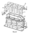
- Figs. 9 and 10 show a construction of the coil assemblies 60, 61 and 62 with closed-end tubes 71 inserted from the top.
- the conduit assembly 70 has six closed-end tubes 71 with split flow provided by bisecting dividers 72 seen in Fig. 11 .
- a non-planar loop conduit 73 is provided to supply and return fluid between inlet 74 and outlet 75.
- the coil assemblies 60, 61 and 62 are supported on a base plate 64 and held in place with a bracket 65 and long bolts 66.
- a retaining member 67 with six holes is disposed over holes in the coil assemblies 60, 61 and 62 to receive the closed-end tubes 71.
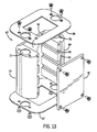
- Figs. 12 and 13 show the bobbin assembly with the coils removed.
- Each bobbin assembly 67, 68, 69 has passageways 77, 78 passing through it parallel to a central axis for the bobbin and along a plane of symmetry from front to back of the bobbin assembly.
- the bobbin assembly 67 has two bobbin end pieces 79, 80 of conducting, but non-ferromagnetic material such as aluminum, spaced apart by planar spacer members 81, 82 of dielectric material as well as by a central cavity 83.
- the edges of the planar spacer members 81, 82 fit in grooves 84 formed in the end pieces 79, 80.
- the end pieces 79, 80 have transverse grooves 85 formed in them to reduce fringing effects. End caps 86, 87 of dielectric material are attached to opposite ends. One leg of the ferromagnetic core 89 would extend through the central cavity 83 of each bobbin assembly.
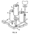
- Fig. 14 shows a cooling base plate assembly 50 as seen in Fig. 1 for cooling capacitors 90.
- the closed-end tubes 46-49 therein extend into the cores of the capacitors 90.
- This capacitor core is made of non-magnetic material and an annular member of dielectric material is disposed around the capacitor core.
- a pair of end pieces of dielectric material 91 are disposed on opposite ends of the capacitor 90.
- Other tubes 46, 47 can be received in other capacitors as shown in Fig. 14 .
- heat pipes can be used instead of the closed-end tubes.
- the fluid is often aided by wicking action of a wicking medium and a liquid often changes phase between liquid and a vapor.
- the invention discloses a cooling system for electrical components in which cooling assemblies are inserted in non-magnetic cores of the electrical components, and in which tubes provide both inflow and outflow of a cooling medium.
- the non-magnetic cores may be bobbins for an inductor assembly or the core of a capacitor.
- the tubes may form a loop in more than one plane to prevent inducing current in a single turn, or they may be split-flow closed-end tubes inserted from one end of the electrical component.
- the bobbin cores are also constructed with a non-conductive portion to prevent inducing a current in a single turn of a conductor.
Landscapes
- Engineering & Computer Science (AREA)
- Power Engineering (AREA)
- Coils Of Transformers For General Uses (AREA)
Description
- The field of the invention is cooling systems and methods for electrical control equipment and components.
- Recent developments in hybrid vehicles and defense applications have increased the demand for cooling systems for electrical control equipment and components.
- The cooling of electrical components lowers their temperature of operation and increases their electrical efficiency and power output per unit size. Electrical resistance, for example, increases with heating and causes the equipment to be less efficient. The size and weight of electrical components can be reduced for a·given power rating, provided that operating temperatures are kept within a certain range of ambient temperature by the use of cooling systems.
- It is typical to mount electrical controls in enclosures. Cooling of the electrical equipment is also beneficial in that removes heat from such enclosures and in some cases allows for sealed enclosures.
- One category of electrical components includes inductors which are electromagnetic devices having an electromagnetic core, often made of ferromagnetic metal, and coils with many turns of electrical wire. These include transformer, choke coils and many other devices using such electromagnetic components.
- In the prior art, many solutions to cooling such devices have included air cooling with radiating fins attached to the components. Traditional, air-cooled inductors are volumetrically inefficient. Large surface areas are required to reject the heat. These components are large in size and have significant weight. Sealed boxes containing inductors of considerable size cannot be adequately air-cooled.
- A known transformer cooling method disclosed in
US 6,157,282 A relates to a cooling system for a transformer. A winding defining a coil, including a duct having an open top and bottom, is sealed to a sleeve, thus forming a closed circulatory path. A fluid is retained and circulated within the circulatory path. - In the document
EP 1 175 135 A1 a heat sink is disclosed. This heat sink has high thermal conductivity as well as satisfactory moldability and corrosion resistance by using a malleable material made of aluminum or aluminum alloy. Liquid cooled heat sink has a passage in which coolant is able to pass, and is joined to a ceramic substrate. A plurality of through holes extending from one end to the other end are formed by a plurality of dividing walls through in flat casing of which both ends are open, and notches are formed on one or both ends of the plurality of dividing walls. Corrugated fins are, respectively, inserted into each of the plurality of through holes, and each through hole is demarcated into a plurality of slots extending from one end to the other end of the casing by these fins. Both ends of the casing are closed by a pair of covers and, and coolant inlet and outlet are formed in the covers. The above passage is formed by communication of the notches and slots, and the above inlet and outlet are positioned on both ends of the passage. - In liquid cooled devices, several approaches have been used. Sometimes tubes have been wrapped around the cores with the wiring for the coils. In some cases, the coils have been immersed in liquids within their enclosures.
- In any approach care must be taken not to short the turns of the coil or to reduce the inductance or other electrical properties of the component due to the addition of the cooling system.
- A cooling system is provided for electrical components in which passageways are provided in non-magnetic cores of the electrical components, and in which the passageways provide both inflow and outflow of a cooling medium. The non-magnetic cores may be bobbins for an inductor assembly or the core of a capacitor. The passageways may be contained within tubes may form a loop in more than one plane to prevent inducing current in a single turn, or they may be split-flow closed-end tubes inserted from one end of the electrical component.
- In the prior art it has been typical either to provide conduits running through the magnetic core or to provide conduits around the coils of an inductor assembly.
- The invention as claimed in
claims 1 and 12 provides a bobbin core of non-magnetic material having a central opening therethrough and having two portions spaced apart to form a gap and a bobbin member disposed over the core, the bobbin member being made of a dielectric material. An electrical component including a coil having a plurality of turns is disposed over the bobbin member and a pair of end pieces of dielectric material are disposed on opposing ends of the bobbin core and extend parallel the plurality of turns. Holes extend into the end pieces and into the bobbin core extending into the core in a direction normal to the electrical component. These holes are adapted to accept tubes for a cooling medium are and for circulating the cooling medium within the bobbin core to cool the electrical component. - Cooling conduits are further arranged to run through the bobbin in a direction perpendicular to the coils to minimize possible negative effects on the electrical properties of the coils. These conduits can either terminate in the bobbin or continue through the bobbin to form a loop in more than one plane. The possibility of inducing a current in a single turn of a coil positioned in one plane is avoided. In addition, the conduit assembly for the cooling system can be shielded from the coil windings by dielectric end plates. The conduit assembly also minimizes the number of transverse portions in preference for portions that are in a direction perpendicular to the coils.
- With this approach the turns of the coils are not susceptible to shorting or diminution of their electrical properties of the component due to the addition of the cooling system.
- The bobbin assemblies can also use a construction that provides an air gap between two half sections of the bobbin core.
- The present invention allows the liquid-cooled inductors to be smaller and of less weight. It also minimizes internal heating of a closed container. It allows redirection of heat energy outside of the system to a desired heat exchanging location.
- The invention will produce lower electrical losses than an equivalent air-cooled design, due to decreased heating.
- The invention will lower the internal temperature of any electrical equipment enclosure, thus demanding less air stirring and exhaust without the excess heat of the inductor. It may also allow the use of lower-temperature components within the enclosure.
- The invention will lower the losses due to heat, reduce internal enclosure temperature, reduce the size of fans that remove heat and other electrical components, and will allow for lower temperature rated components
- The invention will reduce the heat load of internal devices upon the "thermal rejection" system.
- The invention will provide smaller inductors, due to increased allowable flux density, so that smaller cores and smaller coils can be used.
- The invention will be a smaller device, which reduces shipping weight, required package structural strength, and material mass. All of these factors translate to decreased cost.
- The invention will allow for the packaging of this inductor into applications (environments) where air-cooled inductors are not possible.
- The invention is also applicable to other electrical components such as capacitors.
- These and other objects and advantages of the invention will be apparent from the description that follows and from the drawings which illustrate embodiments of the invention, and which are incorporated herein by reference.
-
-
Fig. 1 is a front perspective view of the inductor assembly assembled to a cooling plate; -
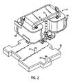
Fig. 2 is a partially exploded view ofFig. 1 ; -
Fig. 3 is a bottom perspective view of the inductor assembly with a cooling system as seen inFig. 2 ; -
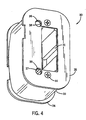
Fig. 4 is a bottom perspective view of an individual bobbin assembly of the present invention; -
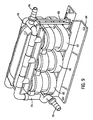
Fig. 5 is an exploded view of the bobbin assembly ofFig. 4 ; -
Fig. 6 is a perspective assembly view an inductor assembly using bobbins of the present invention and using a cooling system with closed-end tubes; -
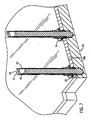
Fig. 7 is a detail sectional view of a cooling tube portion of the assembly ofFig. 6 ; -
Fig. 8 is detail sectional view of the cooling tube ofFig. 7 taken in a plane that is orthogonal to the section inFig. 7 ; -
Fig. 9 is a perspective view of a second type of inductor assembly of the present invention; -
Fig. 10 is a partially exploded perspective view of the assembly ofFig. 9 ; -
Fig. 11 is a detail view of portion of a subassembly seen inFig. 10 ; -
Fig. 12 is a detail perspective view of another subassembly seen inFig. 10 ; -
Fig. 13 is a detail exploded view of one of another bobbin assemblies ofFig. 12 ; and -
Fig. 14 shows a cooling assembly ofFigs. 6 and7 used to cool capacitive components. -
Fig. 1 illustrates aninductor assembly 10, which is a choke coil assembly. Thechoke coil assembly 10 has aconduit assembly 11 for circulating a cooling fluid. As seen inFigs. 1-3 , theconduit assembly 11 is connected byvertical feed conduits couplings conduit stubs cooling base plate 18. Thisbase plate 18 has hollow portions for conveying the cooling fluid into and out of theconduit assembly 11 associated with thechoke coil assembly 10. As seen inFig. 1-3 , theconduit assembly 11 forms a loop in three planes with two horizontal transverse runs 19, 20 across the top, four vertical runs 21, 22, 23 and 24 through thecoil assemblies - The
conduit assembly 11 is referred to as a "pass-through" type of conduit assembly because its conduit tubes allow cooling fluid to pass completely through thecoil assemblies coil assemblies - As further seen in
Figs. 1-3 , thechoke coil assembly 11 has twocoil assemblies outside legs legged core 40 of ferromagnetic material. As seen inFig. 5 , eachcoil assembly bobbin assembly 30 having abobbin core 31, ahollow bobbin 32 that fits over thebobbin core 31, acoil 33 of multiple turns of an insulated conductor that fits over thebobbin 32 and a pair ofend caps bobbin core 31 in this instance is C-shaped with two end portions separated by a gap (in this case, an air gap) to prevent a complete circuit in which a current could be induced to provide what is referred to a "shorting turn." The bobbin core is metallic, preferably aluminum, which is a conductor, but is not a ferromagnetic material. Thebobbin 32 and the end caps 34, 35 are made of a synthetic, dielectric material, again so as not to allow a current to be induced in them to cause a "shorted turn." They are fastened to thebobbin core 31 usingsuitable fasteners 44. As seen inFig. 4 , twoholes Liners hole holes holes bobbin core 31 and normal to the turns of thecoil 33, so as not to have a current induced in them. -
Fig. 6 shows an embodiment of the claimed inductor assembly in which theinductor assembly 20, includingcoil assemblies Figs. 1-5 , but in which a closed-end cooling assembly 45 is used to provide cooling to theinductor assembly 20. This coolingassembly 45 includes four closed-end tubes manifold 50. Thesetubes manifold 50, either by threaded connections or by welding. A closed-end tube 46 (a tube with one closed end), as seen inFigs. 6 and7 , is inserted from underneath thetop surface 50a of thebase plate 50 into the core of anelectrical component tube 46 has abase portion 54 for mounting to thetop plate 50a. The two light vertical lines inFig. 7 define a sectioned wall of thetube 46. Each closed-end tube 46 has apartition member 52 that splits the flow into two portions with the split flow communicating through an internallateral passageway 53 above thepartition 52 and near an upper end of thetube 51. Although the flow is divided in this way, it can be divided in other ways, with a concentric type of divider. Although the tubes herein are shown as cylindrical, as used herein the term "tubes" should be understood to have other possible cross-sectional shapes such as rectangular. -
Figs. 9 and10 show a construction of thecoil assemblies end tubes 71 inserted from the top. Theconduit assembly 70 has six closed-end tubes 71 with split flow provided by bisectingdividers 72 seen inFig. 11 . Anon-planar loop conduit 73 is provided to supply and return fluid betweeninlet 74 andoutlet 75. Thecoil assemblies base plate 64 and held in place with abracket 65 andlong bolts 66. A retainingmember 67 with six holes is disposed over holes in thecoil assemblies end tubes 71. -
Figs. 12 and13 show the bobbin assembly with the coils removed. Eachbobbin assembly passageways Fig. 13 , thebobbin assembly 67 has twobobbin end pieces planar spacer members central cavity 83. The edges of theplanar spacer members grooves 84 formed in theend pieces end pieces transverse grooves 85 formed in them to reduce fringing effects. End caps 86, 87 of dielectric material are attached to opposite ends. One leg of theferromagnetic core 89 would extend through thecentral cavity 83 of each bobbin assembly. -
Fig. 14 shows a coolingbase plate assembly 50 as seen inFig. 1 for coolingcapacitors 90. The closed-end tubes 46-49 therein extend into the cores of thecapacitors 90. This capacitor core is made of non-magnetic material and an annular member of dielectric material is disposed around the capacitor core. A pair of end pieces ofdielectric material 91 are disposed on opposite ends of thecapacitor 90. There is at least one hole formed in one of theend pieces 91 and passing into the core in a direction normal to the electrical component. This hole accepts atube 48 for a cooling medium for circulating the cooling medium within the core to cool thecapacitor 90.Other tubes Fig. 14 . - Thus, the principles of the present invention may be applied to other electrical components besides inductors. Also, heat pipes can be used instead of the closed-end tubes. In heat pipes, the fluid is often aided by wicking action of a wicking medium and a liquid often changes phase between liquid and a vapor.
- In summary the invention discloses a cooling system for electrical components in which cooling assemblies are inserted in non-magnetic cores of the electrical components, and in which tubes provide both inflow and outflow of a cooling medium. The non-magnetic cores may be bobbins for an inductor assembly or the core of a capacitor. The tubes may form a loop in more than one plane to prevent inducing current in a single turn, or they may be split-flow closed-end tubes inserted from one end of the electrical component. The bobbin cores are also constructed with a non-conductive portion to prevent inducing a current in a single turn of a conductor.
- This has been a description of several preferred embodiments of the invention. It will be apparent that various modifications and details can be varied without departing from the scope of the invention, and these are intended to come within the scope of the following claims.
Claims (20)
- A bobbin assembly for an electrical component, the bobbin assembly having:a bobbin core (31) of non-magnetic, conductive material having a central opening therethrough and having two portions spaced apart to form a non-conducting portion therebetween;a bobbin member (32) disposed over the core, the bobbin member being made of a dielectric material;an electrical component including a coil (33) having a plurality of turns disposed over the bobbin member;a pair of end pieces of dielectric material disposed on opposite ends of the bobbin core (31) and extending parallel to the electrical component; characterised in thatat least one hole (36, 37) is formed in said end pieces and said bobbin core (31), the hole passing through the core in a direction normal to the plurality of turns, said hole being adapted to accept a closed-end tube (46, 47, 48, 49) for a cooling medium and for circulating the cooling medium within the bobbin core to cool the electrical component.
- The bobbin assembly of claim 1, wherein the electrical component is an inductor disposed around said bobbin member.
- The bobbin assembly of claim 1 or 2, wherein the non-conducting portion between the two portions of the bobbin core is an air gap.
- The bobbin assembly of claim 1, 2 or 3, wherein the non-conducting portion between the two portions of the bobbin core (31) is provided at least in part by a dielectric material.
- The bobbin assembly of one of claims 1 to 4, wherein the bobbin core (31) is formed of aluminum.
- The bobbin assembly of one of claims 1 to 5, wherein the holes are formed in said end pieces and in said bobbin core and are disposed nearer to two corners of the bobbin core than to two opposite corners of the bobbin core.
- The bobbin assembly of one of claims 1 to 6, wherein the holes are formed in said end pieces and said bobbin core and are disposed along a plane of symmetry running from front to back through the bobbin assembly.
- The bobbin assembly of one of claims 1 to 7, in combination with a conduit assembly (11) including pass-through conduits for conveying a cooling medium through the holes from an inlet to an outlet.
- The bobbin assembly of claim 8, wherein the conduit assembly (11) forms a loop that lies in more than one plane.
- The bobbin assembly of one of claims 1 to 9, in combination with a conduit assembly including closed-end tubes for conveying a cooling medium into and out of the tubes to provide a split flow.
- The bobbin assembly of claim 10, wherein said closed-end tubes have a partition (52) therein for dividing an interior of the tube into an inflow portion and an outflow portion.
- An inductor assembly for receiving cooling components, the inductor assembly comprising:a pair of coil assemblies, each having an opening therethrough;a magnetic core having legs for passing through respective openings in the coil assemblies;wherein the coil assemblies comprise:a bobbin core (31) of non-magnetic material having a central opening therethrough and having two portions spaced apart to form a non-conductive part therebetween;a bobbin member disposed over the core, said bobbin member being made of a dielectric material;an electrical component including a coil (33) having a plurality of turns disposed over the bobbin member;a pair of end pieces of dielectric material disposed on opposite ends of the bobbin and extending parallel to the plurality of turns; anda pair of holes (36, 37) formed in said end pieces and extending into said bobbin core (31) in a direction normal to the plurality of turns, said holes being adapted to accept closed-end tubes (46, 47, 48, 49, 71) for a cooling medium and for circulating the cooling medium within the bobbin core to cool the electrical component.
- The inductor assembly of claim 12, in combination with a conduit assembly including pass-through conduits for conveying a cooling medium through the holes from an inlet to an outlet of the holes.
- The bobbin assembly of claim 13, wherein the conduit assembly forms a loop that lies in more than one plane.
- The bobbin assembly of claim 12, 13 or 14 in combination with a conduit assembly including closed-end tubes for conveying a cooling medium into and out of the holes to provide a split flow.
- The combination of claim 15, wherein said closed-end tubes have a partition therein for bisecting an interior of the tube into an inflow portion and an outflow portion.
- A cooling assembly for cooling of an electrical component, the cooling assembly (45) comprising:a supply portion with a hollow portion for circulation of a cooling medium; anda plurality of tubes for circulating the cooling medium into and out of a bobbin core (31) of an electrical component including a coil (33) having a plurality of turns disposed over a bobbin member (32);wherein the tubes are closed end tubes (46, 47, 49) (71) each having one end for communicating with the supply portion; and
wherein the cooling assembly can be assembled to an electrical component by insertion into holes (36, 37) in the electrical component. - The cooling assembly of claim 17, wherein the electrical component is an inductor.
- The cooling assembly of claim 17, wherein the electrical component is a capacitor.
- The cooling assembly of claim 17, 18 or 19 wherein the tubes together with the supply portion form a loop.
Applications Claiming Priority (1)
| Application Number | Priority Date | Filing Date | Title |
|---|---|---|---|
| US10/932,244 US7129808B2 (en) | 2004-09-01 | 2004-09-01 | Core cooling for electrical components |
Publications (3)
| Publication Number | Publication Date |
|---|---|
| EP1641003A2 EP1641003A2 (en) | 2006-03-29 |
| EP1641003A3 EP1641003A3 (en) | 2006-07-12 |
| EP1641003B1 true EP1641003B1 (en) | 2009-04-15 |
Family
ID=35500644
Family Applications (1)
| Application Number | Title | Priority Date | Filing Date |
|---|---|---|---|
| EP05019009A Expired - Lifetime EP1641003B1 (en) | 2004-09-01 | 2005-09-01 | Cooling of a bobbin assembly for an electrical component |
Country Status (3)
| Country | Link |
|---|---|
| US (1) | US7129808B2 (en) |
| EP (1) | EP1641003B1 (en) |
| DE (1) | DE602005013872D1 (en) |
Families Citing this family (54)
| Publication number | Priority date | Publication date | Assignee | Title |
|---|---|---|---|---|
| US7893804B2 (en) * | 2007-06-27 | 2011-02-22 | Rockwell Automation Technologies, Inc. | Electric coil and core cooling method and apparatus |
| US20090066465A1 (en) * | 2007-09-06 | 2009-03-12 | Udo Ausserlechner | Magnetic core for testing magnetic sensors |
| US8081462B2 (en) | 2007-09-13 | 2011-12-20 | Rockwell Automation Technologies, Inc. | Modular liquid cooling system |
| EP2193530B1 (en) * | 2007-09-28 | 2016-09-14 | Siemens Aktiengesellschaft | Electric winding body and transformer having forced cooling |
| US7710228B2 (en) * | 2007-11-16 | 2010-05-04 | Hamilton Sundstrand Corporation | Electrical inductor assembly |
| DE102008004342B3 (en) * | 2008-01-09 | 2009-07-30 | Mdexx Gmbh | Arrangement with at least one electrical winding |
| US7508289B1 (en) * | 2008-01-11 | 2009-03-24 | Ise Corporation | Cooled high power vehicle inductor and method |
| CH698904A2 (en) * | 2008-05-27 | 2009-11-30 | Alexander Stoev | Water-cooled reactor. |
| FI122043B (en) * | 2008-08-13 | 2011-07-29 | Abb Oy | Frequency converter choke |
| US8497601B2 (en) | 2008-09-27 | 2013-07-30 | Witricity Corporation | Wireless energy transfer converters |
| US9093853B2 (en) | 2008-09-27 | 2015-07-28 | Witricity Corporation | Flexible resonator attachment |
| US8947186B2 (en) | 2008-09-27 | 2015-02-03 | Witricity Corporation | Wireless energy transfer resonator thermal management |
| US8937408B2 (en) | 2008-09-27 | 2015-01-20 | Witricity Corporation | Wireless energy transfer for medical applications |
| US8125304B2 (en) * | 2008-09-30 | 2012-02-28 | Rockwell Automation Technologies, Inc. | Power electronic module with an improved choke and methods of making same |
| US7692525B1 (en) * | 2008-09-30 | 2010-04-06 | Rockwell Automation Technologies, Inc. | Power electronic module with an improved choke and methods of making same |
| GB2463935B (en) * | 2008-10-01 | 2013-06-19 | 3Di Power Ltd | Inductor for high frequency applications |
| DE102009030067A1 (en) * | 2009-06-22 | 2011-01-05 | Mdexx Gmbh | Heat sink for a choke or a transformer and inductor and transformer with such a heat sink |
| DE102009030068A1 (en) * | 2009-06-22 | 2010-12-30 | Mdexx Gmbh | Cooling element for a throttle or a transformer and inductor and transformer with such a cooling element |
| US20100277869A1 (en) * | 2009-09-24 | 2010-11-04 | General Electric Company | Systems, Methods, and Apparatus for Cooling a Power Conversion System |
| EP2678930B1 (en) | 2011-02-24 | 2020-04-08 | Crane Electronics, Inc. | Ac/dc power conversion system and method of manufacture of same |
| FR2980626B1 (en) * | 2011-09-28 | 2014-05-16 | Hispano Suiza Sa | ELECTRONIC COIL POWER COMPONENT COMPRISING A THERMAL DRAINAGE SUPPORT |
| FR2980625B1 (en) * | 2011-09-28 | 2013-10-04 | Hispano Suiza Sa | ELECTRONIC COIL POWER COMPONENT COMPRISING A THERMAL DRAINAGE SUPPORT |
| US9888568B2 (en) | 2012-02-08 | 2018-02-06 | Crane Electronics, Inc. | Multilayer electronics assembly and method for embedding electrical circuit components within a three dimensional module |
| US9480415B2 (en) * | 2013-04-26 | 2016-11-01 | Medtronic Navigation, Inc. | Electromagnetic coil apparatuses for surgical navigation and corresponding methods |
| US9559508B2 (en) | 2013-10-10 | 2017-01-31 | Hamilton Sundstrand Corporation | Housings with embedded bus bars and standoffs |
| US9441472B2 (en) | 2014-01-29 | 2016-09-13 | Harris Corporation | Hydrocarbon resource heating system including common mode choke assembly and related methods |
| US10902993B2 (en) * | 2014-06-19 | 2021-01-26 | Sma Solar Technology Ag | Inductor assembly comprising at least one inductor coil thermally coupled to a metallic inductor housing |
| JP6329446B2 (en) * | 2014-07-02 | 2018-05-23 | 株式会社京三製作所 | Impedance bond |
| US9831768B2 (en) | 2014-07-17 | 2017-11-28 | Crane Electronics, Inc. | Dynamic maneuvering configuration for multiple control modes in a unified servo system |
| US9230726B1 (en) * | 2015-02-20 | 2016-01-05 | Crane Electronics, Inc. | Transformer-based power converters with 3D printed microchannel heat sink |
| US9160228B1 (en) | 2015-02-26 | 2015-10-13 | Crane Electronics, Inc. | Integrated tri-state electromagnetic interference filter and line conditioning module |
| US11096605B2 (en) | 2015-03-31 | 2021-08-24 | Medtronic Navigation, Inc. | Modular coil assembly |
| US9293999B1 (en) | 2015-07-17 | 2016-03-22 | Crane Electronics, Inc. | Automatic enhanced self-driven synchronous rectification for power converters |
| EP3147915A1 (en) * | 2015-09-28 | 2017-03-29 | Siemens Aktiengesellschaft | Cooling of an electric choke |
| US9780635B1 (en) | 2016-06-10 | 2017-10-03 | Crane Electronics, Inc. | Dynamic sharing average current mode control for active-reset and self-driven synchronous rectification for power converters |
| CN110192256B (en) * | 2016-11-04 | 2022-03-29 | 普莱默股份公司 | Compact magnetic power cell for power electronic systems |
| US9742183B1 (en) | 2016-12-09 | 2017-08-22 | Crane Electronics, Inc. | Proactively operational over-voltage protection circuit |
| US9735566B1 (en) | 2016-12-12 | 2017-08-15 | Crane Electronics, Inc. | Proactively operational over-voltage protection circuit |
| US10366817B2 (en) | 2017-05-02 | 2019-07-30 | General Electric Company | Apparatus and method for passive cooling of electronic devices |
| US9979285B1 (en) | 2017-10-17 | 2018-05-22 | Crane Electronics, Inc. | Radiation tolerant, analog latch peak current mode control for power converters |
| US10699840B2 (en) | 2017-11-13 | 2020-06-30 | Ford Global Technologies, Llc | Thermal management system for vehicle power inductor assembly |
| US10141862B1 (en) | 2018-03-20 | 2018-11-27 | Ford Global Technologies, Llc | Power supply device |
| KR102579858B1 (en) | 2018-03-30 | 2023-09-18 | 현대자동차주식회사 | High-capacity converter for vehicle |
| US10425080B1 (en) | 2018-11-06 | 2019-09-24 | Crane Electronics, Inc. | Magnetic peak current mode control for radiation tolerant active driven synchronous power converters |
| JP6591031B1 (en) * | 2018-12-06 | 2019-10-16 | 三菱電機株式会社 | Coil device |
| US20230048934A1 (en) * | 2020-01-15 | 2023-02-16 | Hitachi Energy Switzerland Ag | Method for making a dry-type transformer, dry-type transformer obtained from said method, and dielectric barrier arrangement for electrically isolating a coil of a transformer assembly |
| US12040118B2 (en) * | 2020-11-30 | 2024-07-16 | Hamilton Sundstrand Corporation | Cooling system for a transformer and a method of cooling a transformer |
| TWM613014U (en) * | 2020-12-15 | 2021-06-11 | 飛宏科技股份有限公司 | Choke structure with water cooling |
| CN112908626A (en) * | 2021-01-25 | 2021-06-04 | 合肥博微田村电气有限公司 | Air-cooled reactor |
| EP4060693A1 (en) * | 2021-03-17 | 2022-09-21 | Premo, S.A. | Liquid cooled bobbin for a wire wound magnetic device |
| CN115482991B (en) * | 2021-05-31 | 2023-06-27 | 襄阳中车电机技术有限公司 | Integrated medium-high frequency transformer |
| US12381027B2 (en) * | 2021-10-28 | 2025-08-05 | Ford Global Technologies, Llc. | Power inductor with internal cooling passages |
| CN114823067A (en) * | 2022-05-11 | 2022-07-29 | 广州得羽创科技有限公司 | Transformer with circulation heat radiation structure |
| EP4421830A1 (en) * | 2023-02-24 | 2024-08-28 | Premo, SL | Light liquid cooled power electronic unit |
Family Cites Families (19)
| Publication number | Priority date | Publication date | Assignee | Title |
|---|---|---|---|---|
| BE552492A (en) | ||||
| US3144627A (en) * | 1960-07-05 | 1964-08-11 | Weldex Division Of Metal Craft | Welding transformer with colled core |
| GB1387470A (en) * | 1972-04-10 | 1975-03-19 | Matsushita Electric Industrial Co Ltd | Induction heating equipment |
| US4482879A (en) * | 1983-02-24 | 1984-11-13 | Park-Ohio Industries, Inc. | Transformer core cooling arrangement |
| US4897627A (en) * | 1985-06-21 | 1990-01-30 | Magnetek Universal Mfg. Corp. | Fluorescent ballast assembly including a strip circuit board |
| US4739825A (en) * | 1986-01-14 | 1988-04-26 | General Electric Company | Apparatus for cooling the core of a liquid cooled transformer |
| DE3828724C2 (en) * | 1988-08-24 | 1994-07-14 | Hofmann Werkstatt Technik | Device for driving a motor vehicle wheel mounted on a motor vehicle and jacked up for unbalance determination |
| US4902998A (en) * | 1988-11-21 | 1990-02-20 | Westinghouse Electric Corp. | Inductor assembly with cooled winding turns |
| US4956626A (en) | 1989-01-13 | 1990-09-11 | Sundstrand Corporation | Inductor transformer cooling apparatus |
| US5466052A (en) * | 1992-08-31 | 1995-11-14 | Caterpillar Inc. | A fluid connecting device |
| US5380956A (en) * | 1993-07-06 | 1995-01-10 | Sun Microsystems, Inc. | Multi-chip cooling module and method |
| CA2181215A1 (en) * | 1995-08-28 | 1997-03-01 | Raimund Bruckner | Method of operating an inductor and inductor for carrying out the method |
| DE19846156C1 (en) * | 1998-10-07 | 2000-07-27 | Bosch Gmbh Robert | Arrangement of a multi-phase converter |
| US6157282A (en) * | 1998-12-29 | 2000-12-05 | Square D Company | Transformer cooling method and apparatus therefor |
| JP3907912B2 (en) | 2000-03-30 | 2007-04-18 | 株式会社ソディック | Primary member for linear DC motor and linear DC motor |
| JP2002098454A (en) | 2000-07-21 | 2002-04-05 | Mitsubishi Materials Corp | Liquid-cooled heat sink and method of manufacturing the same |
| US6661327B1 (en) * | 2002-06-12 | 2003-12-09 | Netec Ag | Electromagnetic inductor and transformer device and method making the same |
| FI118397B (en) | 2004-02-13 | 2007-10-31 | Abb Oy | Liquid cooled choke |
| DE102004021107A1 (en) | 2004-04-29 | 2005-11-24 | Bosch Rexroth Ag | Liquid cooling for iron core and winding packages |
-
2004
- 2004-09-01 US US10/932,244 patent/US7129808B2/en not_active Expired - Fee Related
-
2005
- 2005-09-01 DE DE602005013872T patent/DE602005013872D1/en not_active Expired - Lifetime
- 2005-09-01 EP EP05019009A patent/EP1641003B1/en not_active Expired - Lifetime
Also Published As
| Publication number | Publication date |
|---|---|
| US7129808B2 (en) | 2006-10-31 |
| EP1641003A3 (en) | 2006-07-12 |
| US20060044103A1 (en) | 2006-03-02 |
| DE602005013872D1 (en) | 2009-05-28 |
| EP1641003A2 (en) | 2006-03-29 |
Similar Documents
| Publication | Publication Date | Title |
|---|---|---|
| US7129808B2 (en) | Core cooling for electrical components | |
| US7212406B2 (en) | Cooling of electrical components with split-flow closed-end devices | |
| US8614617B2 (en) | Reactor | |
| US8519813B2 (en) | Liquid cooled inductor apparatus and method of use thereof | |
| US9511377B2 (en) | High gradient, oil-cooled iron removal device with inner circulation | |
| US4956626A (en) | Inductor transformer cooling apparatus | |
| US8816808B2 (en) | Method and apparatus for cooling an annular inductor | |
| EP2920797B1 (en) | Apparatus and method for thermal management of magnetic devices | |
| US8203411B2 (en) | Potted inductor apparatus and method of use thereof | |
| US8624696B2 (en) | Inductor apparatus and method of manufacture thereof | |
| US10068696B2 (en) | Magnetic device | |
| US20120223792A1 (en) | Phase change inductor cooling apparatus and method of use thereof | |
| US20230317338A1 (en) | Winding support for a magnetic component of an electrical assembly | |
| TWI707368B (en) | Common mode choke coil | |
| KR102807551B1 (en) | Liquid Cooled Bobbin for Wound High Frequency Magnetic Devices | |
| EP3067903A1 (en) | Electromagnetic induction apparatus | |
| EP3731246B1 (en) | Self-contained cooling device for an electromagnetic interference filter | |
| US8947187B2 (en) | Inductor apparatus and method of manufacture thereof | |
| US9190203B2 (en) | Transformer cooling apparatus and transformer assembly including the same | |
| CN103348421B (en) | Cooling system for dry-type transformer | |
| US20190237242A1 (en) | Transformer unit for a resonant converter | |
| EP3544034B1 (en) | Non-contact power supply connection unit, non-contact power supply device, and operating machine | |
| WO2016137792A1 (en) | Vibration stabilizer for enclosure cooling fins | |
| US20230033439A1 (en) | Electrotechnical device for an aircraft | |
| KR101127176B1 (en) | Cooler of columnar transformer for substation |
Legal Events
| Date | Code | Title | Description |
|---|---|---|---|
| PUAI | Public reference made under article 153(3) epc to a published international application that has entered the european phase |
Free format text: ORIGINAL CODE: 0009012 |
|
| AK | Designated contracting states |
Kind code of ref document: A2 Designated state(s): AT BE BG CH CY CZ DE DK EE ES FI FR GB GR HU IE IS IT LI LT LU LV MC NL PL PT RO SE SI SK TR |
|
| AX | Request for extension of the european patent |
Extension state: AL BA HR MK YU |
|
| PUAL | Search report despatched |
Free format text: ORIGINAL CODE: 0009013 |
|
| AK | Designated contracting states |
Kind code of ref document: A3 Designated state(s): AT BE BG CH CY CZ DE DK EE ES FI FR GB GR HU IE IS IT LI LT LU LV MC NL PL PT RO SE SI SK TR |
|
| AX | Request for extension of the european patent |
Extension state: AL BA HR MK YU |
|
| 17P | Request for examination filed |
Effective date: 20061219 |
|
| AKX | Designation fees paid |
Designated state(s): DE FI FR GB IT |
|
| GRAP | Despatch of communication of intention to grant a patent |
Free format text: ORIGINAL CODE: EPIDOSNIGR1 |
|
| GRAS | Grant fee paid |
Free format text: ORIGINAL CODE: EPIDOSNIGR3 |
|
| GRAA | (expected) grant |
Free format text: ORIGINAL CODE: 0009210 |
|
| AK | Designated contracting states |
Kind code of ref document: B1 Designated state(s): DE FI FR GB IT |
|
| REG | Reference to a national code |
Ref country code: GB Ref legal event code: FG4D |
|
| REF | Corresponds to: |
Ref document number: 602005013872 Country of ref document: DE Date of ref document: 20090528 Kind code of ref document: P |
|
| PLBE | No opposition filed within time limit |
Free format text: ORIGINAL CODE: 0009261 |
|
| STAA | Information on the status of an ep patent application or granted ep patent |
Free format text: STATUS: NO OPPOSITION FILED WITHIN TIME LIMIT |
|
| 26N | No opposition filed |
Effective date: 20100118 |
|
| PGFP | Annual fee paid to national office [announced via postgrant information from national office to epo] |
Ref country code: FI Payment date: 20100929 Year of fee payment: 6 Ref country code: IT Payment date: 20100923 Year of fee payment: 6 |
|
| PG25 | Lapsed in a contracting state [announced via postgrant information from national office to epo] |
Ref country code: IT Free format text: LAPSE BECAUSE OF NON-PAYMENT OF DUE FEES Effective date: 20110901 Ref country code: FI Free format text: LAPSE BECAUSE OF NON-PAYMENT OF DUE FEES Effective date: 20110901 |
|
| PGFP | Annual fee paid to national office [announced via postgrant information from national office to epo] |
Ref country code: DE Payment date: 20130927 Year of fee payment: 9 |
|
| PGFP | Annual fee paid to national office [announced via postgrant information from national office to epo] |
Ref country code: FR Payment date: 20130919 Year of fee payment: 9 Ref country code: GB Payment date: 20130927 Year of fee payment: 9 |
|
| REG | Reference to a national code |
Ref country code: DE Ref legal event code: R119 Ref document number: 602005013872 Country of ref document: DE |
|
| GBPC | Gb: european patent ceased through non-payment of renewal fee |
Effective date: 20140901 |
|
| REG | Reference to a national code |
Ref country code: DE Ref legal event code: R119 Ref document number: 602005013872 Country of ref document: DE Effective date: 20150401 |
|
| REG | Reference to a national code |
Ref country code: FR Ref legal event code: ST Effective date: 20150529 |
|
| PG25 | Lapsed in a contracting state [announced via postgrant information from national office to epo] |
Ref country code: GB Free format text: LAPSE BECAUSE OF NON-PAYMENT OF DUE FEES Effective date: 20140901 Ref country code: DE Free format text: LAPSE BECAUSE OF NON-PAYMENT OF DUE FEES Effective date: 20150401 |
|
| PG25 | Lapsed in a contracting state [announced via postgrant information from national office to epo] |
Ref country code: FR Free format text: LAPSE BECAUSE OF NON-PAYMENT OF DUE FEES Effective date: 20140930 |