EP1640825B1 - Adressing of an electrical module by a locking mechanism - Google Patents
Adressing of an electrical module by a locking mechanism Download PDFInfo
- Publication number
- EP1640825B1 EP1640825B1 EP04022885A EP04022885A EP1640825B1 EP 1640825 B1 EP1640825 B1 EP 1640825B1 EP 04022885 A EP04022885 A EP 04022885A EP 04022885 A EP04022885 A EP 04022885A EP 1640825 B1 EP1640825 B1 EP 1640825B1
- Authority
- EP
- European Patent Office
- Prior art keywords
- electrical
- module
- electrical device
- identification
- contact
- Prior art date
- Legal status (The legal status is an assumption and is not a legal conclusion. Google has not performed a legal analysis and makes no representation as to the accuracy of the status listed.)
- Active
Links
- 230000006870 function Effects 0.000 abstract description 8
- 238000004891 communication Methods 0.000 description 11
- 238000009434 installation Methods 0.000 description 6
- 230000003993 interaction Effects 0.000 description 3
- 238000012423 maintenance Methods 0.000 description 2
- 230000007257 malfunction Effects 0.000 description 2
- 238000000034 method Methods 0.000 description 2
- 238000012544 monitoring process Methods 0.000 description 2
- 230000008569 process Effects 0.000 description 2
- 238000009423 ventilation Methods 0.000 description 2
- RYGMFSIKBFXOCR-UHFFFAOYSA-N Copper Chemical compound [Cu] RYGMFSIKBFXOCR-UHFFFAOYSA-N 0.000 description 1
- 229910000881 Cu alloy Inorganic materials 0.000 description 1
- 229910000639 Spring steel Inorganic materials 0.000 description 1
- 230000006978 adaptation Effects 0.000 description 1
- 238000004378 air conditioning Methods 0.000 description 1
- 230000002457 bidirectional effect Effects 0.000 description 1
- 230000001413 cellular effect Effects 0.000 description 1
- 239000004020 conductor Substances 0.000 description 1
- 229910052802 copper Inorganic materials 0.000 description 1
- 239000010949 copper Substances 0.000 description 1
- 230000002950 deficient Effects 0.000 description 1
- 238000005516 engineering process Methods 0.000 description 1
- 239000003365 glass fiber Substances 0.000 description 1
- 238000010438 heat treatment Methods 0.000 description 1
- 238000003780 insertion Methods 0.000 description 1
- 230000037431 insertion Effects 0.000 description 1
- NJPPVKZQTLUDBO-UHFFFAOYSA-N novaluron Chemical compound C1=C(Cl)C(OC(F)(F)C(OC(F)(F)F)F)=CC=C1NC(=O)NC(=O)C1=C(F)C=CC=C1F NJPPVKZQTLUDBO-UHFFFAOYSA-N 0.000 description 1
- 230000003287 optical effect Effects 0.000 description 1
- 230000008439 repair process Effects 0.000 description 1
- 230000000284 resting effect Effects 0.000 description 1
- 238000000926 separation method Methods 0.000 description 1
Images


Classifications
-
- H—ELECTRICITY
- H01—ELECTRIC ELEMENTS
- H01R—ELECTRICALLY-CONDUCTIVE CONNECTIONS; STRUCTURAL ASSOCIATIONS OF A PLURALITY OF MUTUALLY-INSULATED ELECTRICAL CONNECTING ELEMENTS; COUPLING DEVICES; CURRENT COLLECTORS
- H01R9/00—Structural associations of a plurality of mutually-insulated electrical connecting elements, e.g. terminal strips or terminal blocks; Terminals or binding posts mounted upon a base or in a case; Bases therefor
- H01R9/22—Bases, e.g. strip, block, panel
- H01R9/24—Terminal blocks
- H01R9/26—Clip-on terminal blocks for side-by-side rail- or strip-mounting
- H01R9/2625—Clip-on terminal blocks for side-by-side rail- or strip-mounting with built-in electrical component
-
- H—ELECTRICITY
- H01—ELECTRIC ELEMENTS
- H01R—ELECTRICALLY-CONDUCTIVE CONNECTIONS; STRUCTURAL ASSOCIATIONS OF A PLURALITY OF MUTUALLY-INSULATED ELECTRICAL CONNECTING ELEMENTS; COUPLING DEVICES; CURRENT COLLECTORS
- H01R13/00—Details of coupling devices of the kinds covered by groups H01R12/70 or H01R24/00 - H01R33/00
- H01R13/62—Means for facilitating engagement or disengagement of coupling parts or for holding them in engagement
- H01R13/639—Additional means for holding or locking coupling parts together, after engagement, e.g. separate keylock, retainer strap
-
- H—ELECTRICITY
- H01—ELECTRIC ELEMENTS
- H01R—ELECTRICALLY-CONDUCTIVE CONNECTIONS; STRUCTURAL ASSOCIATIONS OF A PLURALITY OF MUTUALLY-INSULATED ELECTRICAL CONNECTING ELEMENTS; COUPLING DEVICES; CURRENT COLLECTORS
- H01R9/00—Structural associations of a plurality of mutually-insulated electrical connecting elements, e.g. terminal strips or terminal blocks; Terminals or binding posts mounted upon a base or in a case; Bases therefor
- H01R9/22—Bases, e.g. strip, block, panel
- H01R9/24—Terminal blocks
- H01R9/26—Clip-on terminal blocks for side-by-side rail- or strip-mounting
- H01R9/2625—Clip-on terminal blocks for side-by-side rail- or strip-mounting with built-in electrical component
- H01R9/2658—Clip-on terminal blocks for side-by-side rail- or strip-mounting with built-in electrical component with built-in data-bus connection
Definitions
- the embodiments described below relate to an electrical device with an electrical module for communication between the module and another electrical device.
- Such an electrical device is used for example in complex technical systems, such. As heating, ventilation and air conditioning systems, access and fire control systems or building automation systems generally used.
- EP 1 211 582 describes a building automation system in which a plurality of so-called field devices such. As sensors and actuators to use. Individual plant components communicate in such a building automation system via input and output module systems, referred to below as I / O module systems, and one or more bus systems.
- the I / O module systems form the interfaces between the field devices and other plant components. They are used to convert bus signals of an automation station into signals for the field devices and vice versa.
- the I / O module systems are usually mounted on installation strips and housed in control cabinets. When installing an I / O module system, first install a socket on the installation board and then attach and electrically contact the electrical I / O module to the socket.
- a device referred to in the preamble of claim 1 is kind EP 0 362 985 A known.
- an electrical device that, in an alternative manner, prevents a system malfunction from occurring after service or repair.
- Such an electrical device consists of an electrical module for communication between the electrical module and another electrical device.
- An identification transmitter is provided having a first position in which the electrical module is in a non-operative state and a second position in which the electrical module is in an operative state.
- An identification pick-up is provided which cooperates with the identification transmitter in the second position to evaluate an information defined by the identification transmitter.
- the electrical device has a base that removably receives and electrically contacts the electrical module.
- the base contains the identification transmitter.
- the electrical device allows an alternative addressing concept.
- a removable I / O module becomes a Address allocated and stored in the module.
- the location of the permanently installed base or the wiring to the base is addressed because the information transmitter is located on the base. Accordingly, there is no direct addressing of the removable I / O module. Only when the module is plugged into the socket and contacted is the address or function of the I / O module fixed at that location, e.g. B. as a link to a temperature sensor.
- an electrical device is given below with reference to a building automation system.
- the features of the electrical device may generally be used in any system in which the location of the electrical device within the system is critical to the operation of the system, such as, for example, In a hazard alarm system for buildings and facilities, in an electrical device (eg, a computer), or in an electronic device of a vehicle or aircraft.
- FIG. 1 shows a schematic representation of the basic structure of an embodiment of an arrangement for monitoring, control and / or Regulation of a building automation system.
- a communication medium 1 connects units 2, 3 and an electrical device 6 to enable communication with and between these plant parts.
- the person skilled in the art recognizes that in such an arrangement a plurality of electrical devices 6 can be connected to the communication medium 1, as in FIG FIG. 1 indicated.
- FIG. 1 an embodiment of the electrical device 6 is shown in more detail for illustration. As described in more detail below, shows FIG. 1 the electrical device 6 in a service state.
- the electrical device 6 contains an electrical module 8 and can be connected as an integrated unit directly to the communication medium 1.
- An identification transmitter 14 is provided which has a first position in which the electrical module 8 is in a non-operative state and a second position in which the electrical module 8 is in an operative state.
- an identification pickup 20 is provided which cooperates with the identification transmitter in the second position to evaluate a defined by the identification transmitter information.
- the electrical device 6 includes two components, namely the electrical module 8 and a pedestal 12 which removably receives and electrically contacts the electrical module 8 to facilitate communication between the electrical module 8 and other electrical devices.
- the base 12 includes the identification transmitter 14, which has a first and second position. In the first position, the electrical module 8 is not operationally installed in the base 12. In the second position, the electrical module 8 is installed in the base 12 operatively.
- the electrical module 8 contains the identification receiver 20, which interacts with the identification transmitter 14 in the second position in order to evaluate the information defined by the identification transmitter 14.
- the units 2, 3 are each a control and / or control device, and the electrical device 6 is an I / O module, which is used for the control and adaptation of field devices 5 connected thereto.
- the electrical device 6 can in one embodiment via a further bus system with be connected to other I / O modules, as in FIG. 1 is indicated.
- the electrical device 6 may have an operating device 10 for a user interface.
- the operating device 10 also includes a connection for a screen terminal or a mobile computer.
- the unit 2 is connected via a further communication medium 18 to a superordinate system, for example to a control center. If necessary, the unit 3 is connected to a display terminal or a computer 4.
- the bus systems and technologies that can be used in the arrangement are, for example, LON or LonWorks TM from ECHELON, the European installation bus EIB or the PROFIBUS defined according to German standard DIN 19245.
- the electrical device 6 has a plurality of connection points A, B for the field devices 5.
- the number of implemented connection points per electrical device 6 can be selected within wide limits.
- connection points A, B are basically identical and can be used universally as an input port and output port, z. B. bidirectional and for analog and digital signals.
- the connection point A, B can each have a plurality of connection points (eg 4) for the field device 5.
- the universal connection point A, B can therefore be used for a large number of field device types, specifically for sensors or actuators, that is to say for field devices with analog input, analog output, digital input or digital output, with or without power supply via the connection point A. or B.
- the field device 5 may be, for example, a sensor for detecting a process variable or an actuator for influencing a process variable.
- a temperature sensor, a humidity sensor, an actuator for a ventilation flap, a gas sensor, a switch or an actuator with position feedback can be connected to the connection points A, B.
- FIGS Figures 2.1 and 2.2 an embodiment of the electrical device 6 in various installation states, namely in a non-installed state ( Figure 2.1 ) and an installed state ( Figure 2.2 ).
- the uninstalled state as in Figure 2.1 shown, the electrical module 8 is not mounted on the base 12.
- the information transmitter 14 is not in contact with the information receiver 20 of the electric module 8.
- the electrical module 8 is mounted on the base 12 and electrically contacted. The information transmitter 14 is in contact with the information receiver 20 in this state.
- the information transmitter 14 and the information receiver 20 may be configured to mechanically lock the electrical module 8 when the information transmitter 14 is in contact with the information receiver 20. For example, as soon as a service technician interrupts the contact, the electrical module 8 detects that its operation should be interrupted and switches off automatically. The electrical module 8 can then be safely and safely removed from the base 12.
- the electrical device 6 may also assume a service state, such. In FIG. 1 indicated. In this state, the information transmitter 14 is also not in contact with the information receiver 20.
- the electrical module 8 is located in the base 12, but is no longer in electrical contact with the base 12. By the separation of the electrical module 8 from the base 12 and thus From the field devices 5, these can be safely and safely checked and maintained by a service technician. Since the electrical module 8 and the information transmitter 14 remain mechanically connected to the base 12, the risk of confusion when reinserting with other identical components is excluded or at least substantially reduced.
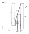
- FIG. 3 and 4 show schematically and simplified part of the electrical module 8, to explain an embodiment in principle.
- the part of the shown electrical module 8 is apparent from a theoretical section through the electrical module 8, which is placed so that a closer environment of the information sensor 20 is visible.
- the person skilled in the art recognizes that this is only an exemplary embodiment and that under certain circumstances additional and / or other elements may be advantageous in order to achieve the desired mechanical or electrical functionalities.
- the electrical module 8 consists of a housing 26 containing the Informationsauf choir 20. Viewed from the outside, in one embodiment, a portion of the information receiver 20 appears as a socket. Outside the housing 26, the information transmitter 14 is indicated, which is formed in one embodiment as a plug which fits into the socket of the information sensor 20. Within the housing 26 is a printed circuit board 21 having a contact pad 22. A contact element 24 has a contact point 28 and is connected directly or indirectly to the housing 26. In FIG. 3 If the information transmitter 14 is not in contact with the information receiver 20 and the contact point 28 does not touch the contact pad 22. The electrical device 6 is therefore either in the uninstalled state or in the service state.
- FIG. 4 shows a portion of the electrical module 8 in the installed state of the electrical device 6.
- the information transmitter 14 in contact with the information sensor 20.
- the information transmitter 14 exerts a force on the contact element 24 and presses the contact element 24 and thus the Contact point 28 in the direction of the printed circuit board 21.
- the contact point 28 touches the contact pad 22.
- the information transmitter 14 therefore establishes an electrical contact, which sets the electrical module 8 in a predetermined state.
- the predetermined state may in one embodiment include one or more functionalities or the assignment of an address. In another embodiment, the predetermined state may be a combination of functionality and address.
- the contact element 24 is in one embodiment, a leaf spring made of an electrically conductive material, for. As copper, a copper alloy or spring steel.
- the leaf spring is attached to the housing 26 so that it is at rest, as in FIG. 3 shown, has no contact with the contact pad 22 and rests on a projection 30. Only the information transmitter 14 presses the leaf spring away from the projection 30 and the contact point 28 against the contact pad 22, so that an electrical contact is formed. As soon as the information transmitter 14 is removed again from the information receiver 20, the contact is interrupted and the contact element 24 assumes the resting state on the projection 30.
- the printed circuit board 21 has a plurality of contact pads 22.
- Each contact pad 22 is associated with a contact point 28 in this embodiment.
- the number of contact pads 22 is therefore equal to the number of contact points 28.
- the number of contact pads 22 and the corresponding contact points 28 can be selected within wide limits and to match desired functionality, allowable module costs and space requirements. In one embodiment for an application in building automation systems typically eight or ten contact points per electrical device 6 are realized.
- the information transmitter 14 is configured according to the number of the contact pads 22 and the contact points 28. That is, the information provider 14 has in one embodiment, a corresponding number of "places" that are occupied either by an element or an exemption. One element presses on a contact element 24, while a free position does not press on any contact element 24. Each contact point may therefore be open or closed, depending on whether the information transmitter 14 presses on a contact element 24 or not. With an example selected number of eight contact points can be z. For example, encode 127 addresses or functions, or a combination of addresses and functions. In one exemplary embodiment, the information transmitter 14 has at least two elements so that a situation in which the information transmitter 14 is inserted can be distinguished from a situation in which the information transmitter 14 is not plugged in.
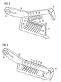
- FIGS. 5 and 6 illustrate schematically an exemplary embodiment for the interaction of information transmitter 14 and information receiver 20.
- FIG. 5 shows the information transmitter 14, which is pivotable about an axis 32 and eight contact elements 24 has.
- the contact elements 24 do not touch the eight contact pads 22 on the board 21 in the idle state.
- the information transmitter 14 could have eight elements T1, T2, T3, T4, T5, T6, T7, T8 However, it does not have any elements in the locations between elements T3, T4 and T4, T5. That is, the elements T4, T6 are not present; they are therefore in FIG. 6 shown by broken lines.
- FIG. 6 is the information transmitter 14 pivoted.
- the elements T1, T2, T3, T5, T7, T8 press the corresponding contact elements 24 against the contact fields 22.
- the contact elements 24, which are not facing any elements (here T4 and T6), are not pressed against the contact pads 22.
- the electrical module 8 does not interpret incorrect addresses or functions when inserting or removing the information transmitter 14.
- element T1 first comes into contact with a contact element 24. Only then do the remaining elements come in contact with their associated contact elements 24.
- the element first closes in one embodiment T8 the circuit. This means that only when the information transmitter 14 is fully inserted does the module 8 receive power.
- the element T8 may be somewhat shorter than the other elements T1-T7. This can additionally ensure that the element T8 presses on a contact element 24 only when all other elements T1-T7 are already in their final position.
- the described electrical device 6 makes it possible to address the location of the electrical device 6 or to determine the functionality of the electrical device 6 at this location.
- the information transmitter 14 can be coded individually for each location by means of the elements T1-T8.
- Such coding may in one embodiment include a reset function by which the electrical module 8 can be placed in an initial state.
- the interaction of the information transmitter 14 and the information receiver 20 allows a mechanical locking of the electrical module 8. This results in an embodiment, a kind of main switch function, since the electric module 8 switches off automatically as soon as the information transmitter 14 is removed from the Informationsetzêt 20.
Abstract
Description
Die im folgenden beschriebenen Ausführungsbeispiele betreffen eine elektrische Einrichtung mit einem elektrischen Modul zur Kommunikation zwischen dem Modul und einer anderen elektrischen Einrichtung.The embodiments described below relate to an electrical device with an electrical module for communication between the module and another electrical device.
Eine solche elektrische Einrichtung kommt beispielsweise in komplexen technischen Systemen, wie z. B. Heizungs-, Lüftungs- und Klimaanlagen, Zutritts- und Feuerüberwachungssysteme oder allgemein Gebäudeautomatisationsanlagen zur Anwendung.
Die I/O Modulsysteme bilden die Schnittstellen zwischen den Feldgeräten und anderen Anlagenteilen. Sie dienen zum Umsetzen von Bussignalen einer Automationsstation in Signale für die Feldgeräte und umgekehrt. Die I/O Modulsysteme sind üblicherweise auf Installationsleisten montiert und in Schaltschränken untergebracht. Bei der Installation eines I/O Modulssystems wird zuerst ein Sockel auf die Installationsleiste montiert und dann das elektrische I/O Modul auf den Sockel befestigt und elektrisch kontaktiert.The I / O module systems form the interfaces between the field devices and other plant components. They are used to convert bus signals of an automation station into signals for the field devices and vice versa. The I / O module systems are usually mounted on installation strips and housed in control cabinets. When installing an I / O module system, first install a socket on the installation board and then attach and electrically contact the electrical I / O module to the socket.
Die Kommunikation über ein Bussystem erfordert typischerweise, dass die einzelnen Feldgeräte und I/O Module adressierbar sind. In der genannten
Bei von einem Sockel zu lösenden elektrischen Einheiten oder Modulen besteht generell die Gefahr, dass bei der Wartung oder dem Austausch von defekten elektrischen Modulen die elektrischen Module vertauscht werden. Dies kann beispielsweise dazu führen, dass ein elektrisches Modul mit einer im System bekannten Adresse nach der Wartung in einem "falschen" Sockel steckt und damit einem anderen Feldgerät zugeordnet ist. Dies kann zu einer Fehlfunktion des Systems führt. Um diese Gefahr zu beheben, beschreibt
Die in
Eine Einrichtung der im Oberbegriff des Anspruchs 1 genannten Art ist aus
Ein Aspekt der im folgenden beschriebenen Ausführungsbeispiele betrifft daher eine elektrische Einrichtung, die auf eine alternative Weise verhindert, dass nach einer Wartung oder Reparatur eine Systemfehlfunktion auftritt. Eine solche elektrische Einrichtung besteht aus einem elektrischen Modul zur Kommunikation zwischen dem elektrischen Modul und einer anderen elektrischen Einrichtung. Ein Identifikationsgeber ist vorhanden, der eine erste Stellung, in der das elektrische Modul in einem nicht operativen Zustand ist, und eine zweite Stellung hat, in der das elektrische Modul in einem operativen Zustand ist. Ein Identifikationsaufnehmer ist vorhanden, der mit dem Identifikationsgeber in der zweiten Stellung zusammen wirkt, um eine vom Identifikationsgeber definierte Information auszuwerten.One aspect of the embodiments described below, therefore, relates to an electrical device that, in an alternative manner, prevents a system malfunction from occurring after service or repair. Such an electrical device consists of an electrical module for communication between the electrical module and another electrical device. An identification transmitter is provided having a first position in which the electrical module is in a non-operative state and a second position in which the electrical module is in an operative state. An identification pick-up is provided which cooperates with the identification transmitter in the second position to evaluate an information defined by the identification transmitter.
In einem Ausführungsbeispiel hat die elektrische Einrichtung einen Sockel, der das elektrische Modul entnehmbar aufnimmt und elektrisch kontaktiert. Der Sockel enthält dabei den Identifikationsgeber.In one embodiment, the electrical device has a base that removably receives and electrically contacts the electrical module. The base contains the identification transmitter.
Die elektrische Einrichtung ermöglicht ein alternatives Adressierungskonzept. Bei bekannten Systemen wird beispielsweise einem entnehmbaren I/O Modul eine Adresse zugeteilt und im Modul gespeichert. Bei der hier beschriebenen elektrischen Einrichtung ist dagegen der Ort des fest installierten Sockels oder die Verkabelung zum Sockel adressiert, da sich der Informationsgeber am Sockel befindet. Es erfolgt demnach keine direkte Adressierung des entnehmbaren I/O Moduls. Erst wenn das Modul in den Sockel gesteckt und kontaktiert ist, ist die Adresse oder die Funktion des I/O Moduls an diesem Ort festgelegt, z. B. als Bindeglied zu einem Temperatursensor.The electrical device allows an alternative addressing concept. In known systems, for example, a removable I / O module becomes a Address allocated and stored in the module. In the case of the electrical device described here, however, the location of the permanently installed base or the wiring to the base is addressed because the information transmitter is located on the base. Accordingly, there is no direct addressing of the removable I / O module. Only when the module is plugged into the socket and contacted is the address or function of the I / O module fixed at that location, e.g. B. as a link to a temperature sensor.
Diese und andere Aspekte, Vorteile und neue Merkmale der im folgenden beschriebenen Ausführungsbeispiele werden in der nachfolgenden detaillierten Beschreibung mit Bezug auf die Zeichnungen erläutert. In den Zeichnungen haben gleiche Elemente die gleichen Bezugszeichen.
-
Figur 1 zeigt den prinzipiellen Aufbau eines Ausführungsbeispiels einer Anordnung zur Überwachung, Steuerung und/oder Regelung einer betriebstechnischen Anlage eines Gebäudes, -
Figuren 2.1 und 2.2 zeigen schematisch ein Ausführungsbeispiel einer elektrischen Einrichtung in verschiedenen Installationszuständen, -
Figur 3 -
Figur 4Figur 3 -
Figuren 5 und 6 illustrieren schematisch ein Ausführungsbeispiel für das Zusammenwirken von Informationsgeber und Informationsaufnehmer.
-
FIG. 1 shows the basic structure of an embodiment of an arrangement for monitoring, control and / or regulation of a technical installation of a building, -
Figures 2.1 and 2.2 show schematically an embodiment of an electrical device in various installation states, -
FIG. 3 shows schematically an embodiment of a part of an electrical module of the electrical device with an information transmitter and an information sensor, -
FIG. 4 shows the clipping according toFIG. 3 in which the information provider is in contact with the information provider, and -
FIGS. 5 and 6 illustrate schematically an embodiment of the interaction of information provider and Informationsaufnehmer.
Die Beschreibung der verschiedenen Ausführungsbeispiele einer elektrischen Einrichtung erfolgt im folgenden mit Bezug auf ein Gebäudeautomationssystem. Der Fachmann wird jedoch erkennen, dass die Merkmale der elektrischen Einrichtung generell in jedem System zur Anwendung kommen können, in dem der Ort der elektrischen Einrichtung innerhalb des Systems für die Funktion des Systems ausschlaggebend ist, wie z. B. bei einem Gefahrenmeldesystem für Gebäude und Anlagen, in einem elektrischen Gerät (z. B. einem Computer), oder in einer elektronischen Einrichtung eines Fahrzeugs oder Flugzeugs.The description of the various embodiments of an electrical device is given below with reference to a building automation system. However, those skilled in the art will recognize that the features of the electrical device may generally be used in any system in which the location of the electrical device within the system is critical to the operation of the system, such as, for example, In a hazard alarm system for buildings and facilities, in an electrical device (eg, a computer), or in an electronic device of a vehicle or aircraft.
In
In einem anderen Ausführungsbeispiel, das in
In einem Ausführungsbeispiel sind die Einheiten 2, 3 je ein Regel- und/oder Steuergerät, und die elektrische Einrichtung 6 ist ein I/O Modul, das zur Steuerung und Adaption von daran verbundenen Feldgeräten 5 dient. Die elektrische Einrichtung 6 kann in einem Ausführungsbeispiel über ein weiteres Bussystem mit anderen I/O Modulen verbunden sein, wie in
Die in der Anordnung einsetzbaren Bussysteme und Technologien sind beispielsweise LON oder LonWorks™ der Firma ECHELON, der Europäische Installationsbus EIB oder der nach deutscher Norm DIN 19245 definierte PROFIBUS. Grundsätzlich sind anstelle des Bussystems oder in Ergänzung dazu auch optische und hybride Datenkommunikationskanäle oder ein Funknetz einsetzbar, beispielsweise ein Glasfasernetz oder ein zellulares Funktelefonnetz, wie etwa GSM oder UMTS.The bus systems and technologies that can be used in the arrangement are, for example, LON or LonWorks ™ from ECHELON, the European installation bus EIB or the PROFIBUS defined according to German standard DIN 19245. In principle, it is also possible to use optical and hybrid data communication channels or a radio network instead of the bus system or in addition thereto, for example a glass fiber network or a cellular radio telephone network, such as GSM or UMTS.
Die elektrische Einrichtung 6 hat mehrere Anschlussstellen A, B für die Feldgeräte 5. Grundsätzlich ist die Anzahl der implementierten Anschlussstellen pro elektrische Einrichtung 6 in weiten Grenzen wählbar.The
Die Anschlussstellen A, B sind grundsätzlich identisch aufgebaut und universal als Eingabeport und als Ausgabeport einsetzbar, z. B. bidirektional und für analoge und digitale Signale. Die Anschlussstelle A, B kann jeweils mehrere Anschlusspunkte (z. B. 4) für das Feldgerät 5 haben. Die universelle Anschlussstelle A, B ist also für eine Vielzahl von Feldgerättypen einsetzbar und zwar für Sensoren oder Aktuatoren, also für Feldgeräte mit Analog-Eingabe, Analog-Ausgabe, Digital-Eingabe oder Digital-Ausgabe, jeweils mit oder ohne Speisung über die Anschlussstelle A oder B. Das Feldgerät 5 kann beispielsweise ein Sensor zur Erfassung einer Prozessgrösse oder ein Stellantrieb zur Beeinflussung einer Prozessgrösse sein. So können beispielsweise an die Anschlussstellen A, B ein Temperaturfühler, ein Feuchtefühler, ein Stellantrieb für eine Lüftungsklappe, ein Gas-Sensor, ein Schalter oder ein Stellglied mit Positionsrückmeldung angeschlossen sein.The connection points A, B are basically identical and can be used universally as an input port and output port, z. B. bidirectional and for analog and digital signals. The connection point A, B can each have a plurality of connection points (eg 4) for the field device 5. The universal connection point A, B can therefore be used for a large number of field device types, specifically for sensors or actuators, that is to say for field devices with analog input, analog output, digital input or digital output, with or without power supply via the connection point A. or B. The field device 5 may be, for example, a sensor for detecting a process variable or an actuator for influencing a process variable. For example, a temperature sensor, a humidity sensor, an actuator for a ventilation flap, a gas sensor, a switch or an actuator with position feedback can be connected to the connection points A, B.
Zum Zweck einer tiefer gehenden Beschreibung zeigen die
In einem Ausführungsbeispiel können der Informationsgeber 14 und der Informationsaufnehmer 20 so ausgeführt sein, dass diese das elektrische Modul 8 mechanisch verriegeln, wenn der Informationsgeber 14 in Kontakt mit dem Informationsaufnehmer 20 ist. Sobald beispielsweise ein Servicetechniker den Kontakt unterbricht, erkennt das elektrische Modul 8, dass sein Betrieb unterbrochen werden soll und schaltet sich automatisch ab. Das elektrische Modul 8 kann dann sicher und gefahrlos aus dem Sockel 12 entnommen werden.In one embodiment, the
In einem Ausführungsbeispiel kann die elektrische Einrichtung 6 ausserdem einen Servicezustand einnehmen, wie z. B. in
Wie in
Das Kontaktelement 24 ist in einem Ausführungsbeispiel eine Blattfeder aus einem elektrisch leitfähigen Material, z. B. Kupfer, eine Kupferlegierung oder Federstahl.The
Die Blattfeder ist so am Gehäuse 26 befestigt, dass sie im Ruhezustand, wie in
In einem Ausführungsbeispiel der elektrischen Einrichtung 6 hat die Leiterplatte 21 mehrere Kontaktfelder 22. Jedem Kontaktfeld 22 ist in diesem Ausführungsbeispiel ein Kontaktpunkt 28 zugeordnet. Die Anzahl der Kontaktfelder 22 ist demnach gleich der Anzahl der Kontaktpunkte 28. Die Anzahl der Kontaktfelder 22 und der entsprechenden Kontaktpunkte 28 ist in weiten Grenzen wählbar und auf gewünschte Funktionalität, zulässige Modulkosten und Platzbedarf abzustimmen. In einem Ausführungsbeispiel für eine Anwendung in Gebäudeautomatisationsanlagen werden typischerweise acht oder zehn Kontaktsstellen pro elektrische Einrichtung 6 verwirklicht.In one embodiment of the
Das in
In einem Ausführungsbeispiel sind spezielle Vorkehrungen getroffen, damit zum Beispiel das elektrische Modul 8 beim Einsetzen bzw. Entfernen des Informationsgebers 14 keine falsche Adressen oder Funktionen interpretiert. Beim Einsetzen, zum Beispiel, kommt das Element T1 zuerst in Kontakt mit einem Kontaktelement 24. Erst danach kommen die verbleibenden Elemente in Kontakt mit den ihnen zugeordneten Kontaktelementen 24. Um während dieser Zeit, undefinierte Zustände zu vermeiden, schliesst in einem Ausführungsbeispiel erst das Element T8 den Stromkreis. Das heisst, erst wenn der Informationsgeber 14 ganz eingeführt ist, erhält das Modul 8 Strom. Zusätzlich zur Funktion den Stromkreis zu schliessen, kann in einem Ausführungsbeispiel das Element T8 etwas kürzer sein als die anderen Elemente T1-T7. Dadurch kann zusätzlich sichergestellt werden, dass das Element T8 erst dann auf ein Kontaktelement 24 drückt, wenn alle anderen Elemente T1-T7 bereits in ihrer endgültigen Position sind.In one embodiment, special precautions are taken so that, for example, the
Die beschriebene elektrische Einrichtung 6 ermöglicht es, den Ort der elektrischen Einrichtung 6 zu adressieren oder die Funktionalität der elektrischen Einrichtung 6 an diesem Ort festzulegen. Dazu kann der Informationsgeber 14 für jeden Ort individuell mittels der Elemente T1-T8 codiert werden. Eine solche Codierung kann in einem Ausführungsbeispiel eine Reset-Funktion enthalten, durch die das elektrische Modul 8 in einen Ausgangszustand versetzt werden kann. Zusätzlich ermöglicht das Zusammenwirken des Informationsgebers 14 und des Informationsaufnehmers 20 eine mechanische Verriegelung des elektrischen Moduls 8. Dadurch ergibt sich in einem Ausführungsbeispiel eine Art Hauptschalterfunktion, da sich das elektrische Modul 8 automatisch abschaltet, sobald der Informationsgeber 14 aus dem Informationsaufnehmer 20 entfernt wird.The described
Claims (12)
- Electrical device (6) having an electrical module (8) for the purpose of communicating between the electrical module (8) and another electrical device,
an identification transmitter (14) being provided which has a first position, in which the electrical module (8) is in a non-operative state, and which has a second position, in which the electrical module (8) is in an operative state, and
an identification pick-up (20) being provided which interacts with the identification transmitter (14) in the second position in order to evaluate information defined by the identification transmitter (14), characterized
in that the identification transmitter (14) is in the form of a plug, and the identification pick-up (20) is in the form of a socket in order to accommodate at least part of the identification transmitter (14). - Electrical device (6) according to Claim 1, in which a base (12) is provided which accommodates the electrical module (8) such that it can be removed and makes electrical contact with it.
- Electrical device (6) according to Claim 2, in which the identification transmitter (14) is arranged on the base (12).
- Electrical device (6) according to Claim 3, in which the electrical module (8), in the non-operative state, is not installed in an operative manner in the base (12) and, in the operative state, is installed in an operative manner in the base (12).
- Electrical device (6) according to one of the preceding Claims 1 to 4, in which the information defines an address for the electrical module (8) in order to identify the electrical module (8) in a system.
- Electrical device (6) according to one of the preceding Claims 1 to 4, in which the information defines a predetermined operative state for the electrical module (8).
- Electrical device (6) according to Claim 1, in which the plug has elements (T1 - T8) which interact with contact elements (24) of the identification pick-up (20).
- Electrical device (6) according to Claim 1, in which the plug contains a combination of elements (T1 - T8) and free locations which interacts with contact elements (24) of the identification pick-up (20).
- Electrical device (6) according to one of Claims 1 to 9, in which the identification pick-up (20) contains leaf springs in the form of contact elements (24).
- Electrical device (6) according to one of Claims 8 to 10, in which the identification transmitter (14) and the identification pick-up (20) bring about latching which mechanically latches the electrical module (8).
- Electrical device (6) according to Claim 11, in which the electrical module (8) is switched off if the latching is released.
- Electrical device (6) according to one of the preceding Claims 2 to 12, in which the identification transmitter (14) is fixed to the base (12) such that it can move.
Priority Applications (5)
| Application Number | Priority Date | Filing Date | Title |
|---|---|---|---|
| DE502004008417T DE502004008417D1 (en) | 2004-09-24 | 2004-09-24 | Addressing of an electrical module by means of locking |
| EP04022885A EP1640825B1 (en) | 2004-09-24 | 2004-09-24 | Adressing of an electrical module by a locking mechanism |
| AT04022885T ATE413636T1 (en) | 2004-09-24 | 2004-09-24 | ADDRESSING AN ELECTRICAL MODULE USING LOCKING |
| US11/232,416 US7442068B2 (en) | 2004-09-24 | 2005-09-21 | Electrical device having a base and an electrical module |
| CN200510106311A CN100576653C (en) | 2004-09-24 | 2005-09-23 | Electric device with a socket and an electrical module |
Applications Claiming Priority (1)
| Application Number | Priority Date | Filing Date | Title |
|---|---|---|---|
| EP04022885A EP1640825B1 (en) | 2004-09-24 | 2004-09-24 | Adressing of an electrical module by a locking mechanism |
Publications (2)
| Publication Number | Publication Date |
|---|---|
| EP1640825A1 EP1640825A1 (en) | 2006-03-29 |
| EP1640825B1 true EP1640825B1 (en) | 2008-11-05 |
Family
ID=34926720
Family Applications (1)
| Application Number | Title | Priority Date | Filing Date |
|---|---|---|---|
| EP04022885A Active EP1640825B1 (en) | 2004-09-24 | 2004-09-24 | Adressing of an electrical module by a locking mechanism |
Country Status (4)
| Country | Link |
|---|---|
| EP (1) | EP1640825B1 (en) |
| CN (1) | CN100576653C (en) |
| AT (1) | ATE413636T1 (en) |
| DE (1) | DE502004008417D1 (en) |
Families Citing this family (5)
| Publication number | Priority date | Publication date | Assignee | Title |
|---|---|---|---|---|
| FR2936908B1 (en) * | 2008-10-07 | 2011-09-23 | Areva T & D Prot Controle | DEVICE AND METHOD FOR PROTECTING A CONNECTION OF A MEDIUM, HIGH OR VERY HIGH VOLTAGE ELECTRICAL NETWORK. |
| CN102195343A (en) * | 2010-03-17 | 2011-09-21 | 胜德国际研发股份有限公司 | Socket device, power source management system and power source management |
| US8628004B2 (en) * | 2010-08-20 | 2014-01-14 | Rockwell Automation Technologies, Inc. | Automation control system components with electronic keying features |
| GB2536194A (en) * | 2015-02-11 | 2016-09-14 | Eaton Ind France Sas | Automatically deducing the electrical cabling between electrical devices |
| US10420232B2 (en) * | 2016-04-21 | 2019-09-17 | Raycap, Surge Protective Devices, Ltd. | DIN rail device mount assemblies, systems and methods including locking mechanisms |
Family Cites Families (3)
| Publication number | Priority date | Publication date | Assignee | Title |
|---|---|---|---|---|
| DE68917405D1 (en) * | 1988-09-05 | 1994-09-15 | Apollo Fire Detectors Ltd | Arrangement for setting markings for identification of a fire detector. |
| ATE161645T1 (en) * | 1991-12-10 | 1998-01-15 | Cerberus Ag | ADDRESSING FOR FIRE, GAS AND BURGLAR DETECTION SYSTEMS |
| US5818334A (en) * | 1995-02-03 | 1998-10-06 | Simplex Time Recorder Company | Addressable devices with interface modules having electrically readable addresses |
-
2004
- 2004-09-24 DE DE502004008417T patent/DE502004008417D1/en active Active
- 2004-09-24 EP EP04022885A patent/EP1640825B1/en active Active
- 2004-09-24 AT AT04022885T patent/ATE413636T1/en active
-
2005
- 2005-09-23 CN CN200510106311A patent/CN100576653C/en active Active
Also Published As
| Publication number | Publication date |
|---|---|
| EP1640825A1 (en) | 2006-03-29 |
| ATE413636T1 (en) | 2008-11-15 |
| CN1797866A (en) | 2006-07-05 |
| DE502004008417D1 (en) | 2008-12-18 |
| CN100576653C (en) | 2009-12-30 |
Similar Documents
| Publication | Publication Date | Title |
|---|---|---|
| EP1815728B1 (en) | Modular automation system | |
| US7442068B2 (en) | Electrical device having a base and an electrical module | |
| DE19605698C1 (en) | Terminal device e.g. for electrical data and signal transmission installation system | |
| EP1356440A1 (en) | Electric domestic appliance comprising a communication interface | |
| EP0346614B1 (en) | Method of initialising a digital signal transmission system | |
| EP2483978A2 (en) | Assembly for installing building systems engineering units | |
| WO2014037586A2 (en) | Plug part for forming a plug connection | |
| DE10335035A1 (en) | System and method for identifying automation components | |
| EP1640825B1 (en) | Adressing of an electrical module by a locking mechanism | |
| WO2018007019A1 (en) | System of automation components and method for operating the same | |
| EP1611713B1 (en) | Switchgear system and method for the installation of withdrawable units into switchgears | |
| DE19515633A1 (en) | Electrical installation for building | |
| EP3799534A1 (en) | Functional module | |
| DE19647823B4 (en) | Control and monitoring device for a smoke and heat exhaust system | |
| EP0437696A1 (en) | Remote-controlled connecting device | |
| DE102010038459A1 (en) | Safety system, has safety module comprising system interface for direct contacting and communication with group protection unit, and load branch comprising another system interface for direct communication with safety module | |
| EP2793238B1 (en) | Fluid technology control system for hydraulic and/or pneumatic actuators | |
| DE2244428C3 (en) | Timing relay | |
| DE102006036964B4 (en) | Modular system for the production of an application-specific electrical assembly and electrical assembly made therefrom | |
| EP2093845B1 (en) | Modular safety control | |
| DE102007022342A1 (en) | Sensor unit with several operating or functional elements | |
| DE19610742A1 (en) | Assembly with a circuit arrangement | |
| DE102019135089A1 (en) | Device for exchanging signals between control and field devices | |
| DE102019126704A1 (en) | INPUT / OUTPUT STATION FOR A FIELDBUS SYSTEM, FIELDBUS COUPLER FOR THE INPUT / OUTPUT STATION, AND PLACEHOLDER MODULE FOR THE INPUT / OUTPUT STATION | |
| WO2018141484A1 (en) | Plug-in data store having independent data store elements, and system of a plug-in data store and at least two system components |
Legal Events
| Date | Code | Title | Description |
|---|---|---|---|
| PUAI | Public reference made under article 153(3) epc to a published international application that has entered the european phase |
Free format text: ORIGINAL CODE: 0009012 |
|
| AK | Designated contracting states |
Kind code of ref document: A1 Designated state(s): AT BE BG CH CY CZ DE DK EE ES FI FR GB GR HU IE IT LI LU MC NL PL PT RO SE SI SK TR |
|
| AX | Request for extension of the european patent |
Extension state: AL HR LT LV MK |
|
| 17P | Request for examination filed |
Effective date: 20060508 |
|
| AKX | Designation fees paid |
Designated state(s): AT BE BG CH CY CZ DE DK EE ES FI FR GB GR HU IE IT LI LU MC NL PL PT RO SE SI SK TR |
|
| 17Q | First examination report despatched |
Effective date: 20071126 |
|
| RAP1 | Party data changed (applicant data changed or rights of an application transferred) |
Owner name: SIEMENS AKTIENGESELLSCHAFT |
|
| GRAP | Despatch of communication of intention to grant a patent |
Free format text: ORIGINAL CODE: EPIDOSNIGR1 |
|
| GRAS | Grant fee paid |
Free format text: ORIGINAL CODE: EPIDOSNIGR3 |
|
| GRAA | (expected) grant |
Free format text: ORIGINAL CODE: 0009210 |
|
| AK | Designated contracting states |
Kind code of ref document: B1 Designated state(s): AT BE BG CH CY CZ DE DK EE ES FI FR GB GR HU IE IT LI LU MC NL PL PT RO SE SI SK TR |
|
| REG | Reference to a national code |
Ref country code: GB Ref legal event code: FG4D Free format text: NOT ENGLISH |
|
| REG | Reference to a national code |
Ref country code: CH Ref legal event code: EP |
|
| REG | Reference to a national code |
Ref country code: IE Ref legal event code: FG4D Free format text: LANGUAGE OF EP DOCUMENT: GERMAN |
|
| REF | Corresponds to: |
Ref document number: 502004008417 Country of ref document: DE Date of ref document: 20081218 Kind code of ref document: P |
|
| REG | Reference to a national code |
Ref country code: CH Ref legal event code: NV Representative=s name: SIEMENS SCHWEIZ AG |
|
| REG | Reference to a national code |
Ref country code: SE Ref legal event code: TRGR |
|
| PG25 | Lapsed in a contracting state [announced via postgrant information from national office to epo] |
Ref country code: ES Free format text: LAPSE BECAUSE OF FAILURE TO SUBMIT A TRANSLATION OF THE DESCRIPTION OR TO PAY THE FEE WITHIN THE PRESCRIBED TIME-LIMIT Effective date: 20090216 |
|
| PG25 | Lapsed in a contracting state [announced via postgrant information from national office to epo] |
Ref country code: SI Free format text: LAPSE BECAUSE OF FAILURE TO SUBMIT A TRANSLATION OF THE DESCRIPTION OR TO PAY THE FEE WITHIN THE PRESCRIBED TIME-LIMIT Effective date: 20081105 Ref country code: FI Free format text: LAPSE BECAUSE OF FAILURE TO SUBMIT A TRANSLATION OF THE DESCRIPTION OR TO PAY THE FEE WITHIN THE PRESCRIBED TIME-LIMIT Effective date: 20081105 |
|
| PG25 | Lapsed in a contracting state [announced via postgrant information from national office to epo] |
Ref country code: RO Free format text: LAPSE BECAUSE OF FAILURE TO SUBMIT A TRANSLATION OF THE DESCRIPTION OR TO PAY THE FEE WITHIN THE PRESCRIBED TIME-LIMIT Effective date: 20081105 Ref country code: EE Free format text: LAPSE BECAUSE OF FAILURE TO SUBMIT A TRANSLATION OF THE DESCRIPTION OR TO PAY THE FEE WITHIN THE PRESCRIBED TIME-LIMIT Effective date: 20081105 Ref country code: DK Free format text: LAPSE BECAUSE OF FAILURE TO SUBMIT A TRANSLATION OF THE DESCRIPTION OR TO PAY THE FEE WITHIN THE PRESCRIBED TIME-LIMIT Effective date: 20081105 Ref country code: BG Free format text: LAPSE BECAUSE OF FAILURE TO SUBMIT A TRANSLATION OF THE DESCRIPTION OR TO PAY THE FEE WITHIN THE PRESCRIBED TIME-LIMIT Effective date: 20090205 |
|
| PG25 | Lapsed in a contracting state [announced via postgrant information from national office to epo] |
Ref country code: PT Free format text: LAPSE BECAUSE OF FAILURE TO SUBMIT A TRANSLATION OF THE DESCRIPTION OR TO PAY THE FEE WITHIN THE PRESCRIBED TIME-LIMIT Effective date: 20090406 Ref country code: CZ Free format text: LAPSE BECAUSE OF FAILURE TO SUBMIT A TRANSLATION OF THE DESCRIPTION OR TO PAY THE FEE WITHIN THE PRESCRIBED TIME-LIMIT Effective date: 20081105 |
|
| PLBE | No opposition filed within time limit |
Free format text: ORIGINAL CODE: 0009261 |
|
| STAA | Information on the status of an ep patent application or granted ep patent |
Free format text: STATUS: NO OPPOSITION FILED WITHIN TIME LIMIT |
|
| PG25 | Lapsed in a contracting state [announced via postgrant information from national office to epo] |
Ref country code: SK Free format text: LAPSE BECAUSE OF FAILURE TO SUBMIT A TRANSLATION OF THE DESCRIPTION OR TO PAY THE FEE WITHIN THE PRESCRIBED TIME-LIMIT Effective date: 20081105 |
|
| 26N | No opposition filed |
Effective date: 20090806 |
|
| BERE | Be: lapsed |
Owner name: SIEMENS A.G. Effective date: 20090930 |
|
| PG25 | Lapsed in a contracting state [announced via postgrant information from national office to epo] |
Ref country code: MC Free format text: LAPSE BECAUSE OF NON-PAYMENT OF DUE FEES Effective date: 20090930 |
|
| PG25 | Lapsed in a contracting state [announced via postgrant information from national office to epo] |
Ref country code: PL Free format text: LAPSE BECAUSE OF FAILURE TO SUBMIT A TRANSLATION OF THE DESCRIPTION OR TO PAY THE FEE WITHIN THE PRESCRIBED TIME-LIMIT Effective date: 20081105 |
|
| PG25 | Lapsed in a contracting state [announced via postgrant information from national office to epo] |
Ref country code: BE Free format text: LAPSE BECAUSE OF NON-PAYMENT OF DUE FEES Effective date: 20090930 |
|
| PG25 | Lapsed in a contracting state [announced via postgrant information from national office to epo] |
Ref country code: GR Free format text: LAPSE BECAUSE OF FAILURE TO SUBMIT A TRANSLATION OF THE DESCRIPTION OR TO PAY THE FEE WITHIN THE PRESCRIBED TIME-LIMIT Effective date: 20090206 |
|
| PG25 | Lapsed in a contracting state [announced via postgrant information from national office to epo] |
Ref country code: LU Free format text: LAPSE BECAUSE OF NON-PAYMENT OF DUE FEES Effective date: 20090924 |
|
| PG25 | Lapsed in a contracting state [announced via postgrant information from national office to epo] |
Ref country code: HU Free format text: LAPSE BECAUSE OF FAILURE TO SUBMIT A TRANSLATION OF THE DESCRIPTION OR TO PAY THE FEE WITHIN THE PRESCRIBED TIME-LIMIT Effective date: 20090506 |
|
| PG25 | Lapsed in a contracting state [announced via postgrant information from national office to epo] |
Ref country code: TR Free format text: LAPSE BECAUSE OF FAILURE TO SUBMIT A TRANSLATION OF THE DESCRIPTION OR TO PAY THE FEE WITHIN THE PRESCRIBED TIME-LIMIT Effective date: 20081105 |
|
| PG25 | Lapsed in a contracting state [announced via postgrant information from national office to epo] |
Ref country code: CY Free format text: LAPSE BECAUSE OF FAILURE TO SUBMIT A TRANSLATION OF THE DESCRIPTION OR TO PAY THE FEE WITHIN THE PRESCRIBED TIME-LIMIT Effective date: 20081105 |
|
| REG | Reference to a national code |
Ref country code: CH Ref legal event code: PUE Owner name: SIEMENS SCHWEIZ AG, CH Free format text: FORMER OWNER: SIEMENS AKTIENGESELLSCHAFT, DE |
|
| REG | Reference to a national code |
Ref country code: GB Ref legal event code: 732E Free format text: REGISTERED BETWEEN 20150220 AND 20150225 |
|
| REG | Reference to a national code |
Ref country code: DE Ref legal event code: R081 Ref document number: 502004008417 Country of ref document: DE Owner name: SIEMENS SCHWEIZ AG, CH Free format text: FORMER OWNER: SIEMENS AKTIENGESELLSCHAFT, 80333 MUENCHEN, DE Effective date: 20150407 |
|
| REG | Reference to a national code |
Ref country code: AT Ref legal event code: PC Ref document number: 413636 Country of ref document: AT Kind code of ref document: T Owner name: SIEMENS SCHWEIZ AG, CH Effective date: 20150421 |
|
| REG | Reference to a national code |
Ref country code: FR Ref legal event code: PLFP Year of fee payment: 12 |
|
| PGFP | Annual fee paid to national office [announced via postgrant information from national office to epo] |
Ref country code: IE Payment date: 20150917 Year of fee payment: 12 |
|
| REG | Reference to a national code |
Ref country code: FR Ref legal event code: TP Owner name: SIEMENS SCHWEIZ AG, CH Effective date: 20160202 |
|
| REG | Reference to a national code |
Ref country code: FR Ref legal event code: PLFP Year of fee payment: 13 |
|
| REG | Reference to a national code |
Ref country code: IE Ref legal event code: MM4A |
|
| PG25 | Lapsed in a contracting state [announced via postgrant information from national office to epo] |
Ref country code: IE Free format text: LAPSE BECAUSE OF NON-PAYMENT OF DUE FEES Effective date: 20160924 |
|
| REG | Reference to a national code |
Ref country code: FR Ref legal event code: PLFP Year of fee payment: 14 |
|
| PGFP | Annual fee paid to national office [announced via postgrant information from national office to epo] |
Ref country code: AT Payment date: 20170807 Year of fee payment: 14 Ref country code: NL Payment date: 20170912 Year of fee payment: 14 |
|
| REG | Reference to a national code |
Ref country code: FR Ref legal event code: PLFP Year of fee payment: 15 |
|
| REG | Reference to a national code |
Ref country code: NL Ref legal event code: MM Effective date: 20181001 |
|
| REG | Reference to a national code |
Ref country code: AT Ref legal event code: MM01 Ref document number: 413636 Country of ref document: AT Kind code of ref document: T Effective date: 20180924 |
|
| PG25 | Lapsed in a contracting state [announced via postgrant information from national office to epo] |
Ref country code: NL Free format text: LAPSE BECAUSE OF NON-PAYMENT OF DUE FEES Effective date: 20181001 |
|
| PG25 | Lapsed in a contracting state [announced via postgrant information from national office to epo] |
Ref country code: AT Free format text: LAPSE BECAUSE OF NON-PAYMENT OF DUE FEES Effective date: 20180924 |
|
| PGFP | Annual fee paid to national office [announced via postgrant information from national office to epo] |
Ref country code: SE Payment date: 20220915 Year of fee payment: 19 |
|
| PGFP | Annual fee paid to national office [announced via postgrant information from national office to epo] |
Ref country code: IT Payment date: 20220926 Year of fee payment: 19 |
|
| PGFP | Annual fee paid to national office [announced via postgrant information from national office to epo] |
Ref country code: CH Payment date: 20221220 Year of fee payment: 19 |
|
| PGFP | Annual fee paid to national office [announced via postgrant information from national office to epo] |
Ref country code: FR Payment date: 20230918 Year of fee payment: 20 |
|
| PGFP | Annual fee paid to national office [announced via postgrant information from national office to epo] |
Ref country code: GB Payment date: 20231009 Year of fee payment: 20 |
|
| PGFP | Annual fee paid to national office [announced via postgrant information from national office to epo] |
Ref country code: DE Payment date: 20231120 Year of fee payment: 20 |