EP1640660A2 - Erosion shielding for a circulating fluidized bed boiler - Google Patents
Erosion shielding for a circulating fluidized bed boiler Download PDFInfo
- Publication number
- EP1640660A2 EP1640660A2 EP05397018A EP05397018A EP1640660A2 EP 1640660 A2 EP1640660 A2 EP 1640660A2 EP 05397018 A EP05397018 A EP 05397018A EP 05397018 A EP05397018 A EP 05397018A EP 1640660 A2 EP1640660 A2 EP 1640660A2
- Authority
- EP
- European Patent Office
- Prior art keywords
- zone
- erosion
- fluidized bed
- circulating fluidized
- wall
- Prior art date
- Legal status (The legal status is an assumption and is not a legal conclusion. Google has not performed a legal analysis and makes no representation as to the accuracy of the status listed.)
- Withdrawn
Links
Images
Classifications
-
- F—MECHANICAL ENGINEERING; LIGHTING; HEATING; WEAPONS; BLASTING
- F23—COMBUSTION APPARATUS; COMBUSTION PROCESSES
- F23M—CASINGS, LININGS, WALLS OR DOORS SPECIALLY ADAPTED FOR COMBUSTION CHAMBERS, e.g. FIREBRIDGES; DEVICES FOR DEFLECTING AIR, FLAMES OR COMBUSTION PRODUCTS IN COMBUSTION CHAMBERS; SAFETY ARRANGEMENTS SPECIALLY ADAPTED FOR COMBUSTION APPARATUS; DETAILS OF COMBUSTION CHAMBERS, NOT OTHERWISE PROVIDED FOR
- F23M5/00—Casings; Linings; Walls
- F23M5/08—Cooling thereof; Tube walls
-
- F—MECHANICAL ENGINEERING; LIGHTING; HEATING; WEAPONS; BLASTING
- F23—COMBUSTION APPARATUS; COMBUSTION PROCESSES
- F23C—METHODS OR APPARATUS FOR COMBUSTION USING FLUID FUEL OR SOLID FUEL SUSPENDED IN A CARRIER GAS OR AIR
- F23C10/00—Fluidised bed combustion apparatus
- F23C10/18—Details; Accessories
-
- F—MECHANICAL ENGINEERING; LIGHTING; HEATING; WEAPONS; BLASTING
- F23—COMBUSTION APPARATUS; COMBUSTION PROCESSES
- F23M—CASINGS, LININGS, WALLS OR DOORS SPECIALLY ADAPTED FOR COMBUSTION CHAMBERS, e.g. FIREBRIDGES; DEVICES FOR DEFLECTING AIR, FLAMES OR COMBUSTION PRODUCTS IN COMBUSTION CHAMBERS; SAFETY ARRANGEMENTS SPECIALLY ADAPTED FOR COMBUSTION APPARATUS; DETAILS OF COMBUSTION CHAMBERS, NOT OTHERWISE PROVIDED FOR
- F23M5/00—Casings; Linings; Walls
-
- F—MECHANICAL ENGINEERING; LIGHTING; HEATING; WEAPONS; BLASTING
- F23—COMBUSTION APPARATUS; COMBUSTION PROCESSES
- F23M—CASINGS, LININGS, WALLS OR DOORS SPECIALLY ADAPTED FOR COMBUSTION CHAMBERS, e.g. FIREBRIDGES; DEVICES FOR DEFLECTING AIR, FLAMES OR COMBUSTION PRODUCTS IN COMBUSTION CHAMBERS; SAFETY ARRANGEMENTS SPECIALLY ADAPTED FOR COMBUSTION APPARATUS; DETAILS OF COMBUSTION CHAMBERS, NOT OTHERWISE PROVIDED FOR
- F23M2900/00—Special features of, or arrangements for combustion chambers
- F23M2900/05004—Special materials for walls or lining
Definitions
- the invention relates to a method for shielding the inner surface above the shield refractory of the furnace wall of a circulating fluidized be boiler from erosion caused by suspension flows according to the preamble of the appended claim 1.
- the invention relates to a circulating fluidized bed boiler according to the preamble of the appended claim 8.
- a complex suspension flow exists in the furnace of a circulating fluidized bed boiler (CFB boiler).
- the suspension flow of the furnace consists essentially of an upward flow in the central area of the furnace, where the density of the suspension decreases from the value of 1,000 kg/m 3 in the lower part to the density of 3 kg/m 3 in the upper part. Particles separate close to the walls from the upward flow along the way in the central area. The speed of the particles is decreased and finally, close to the wall, it turns into a downward flow.
- the downward particle flow is typically approximately 50...100 mm thick and the thickness of the particle film formed by the flow is at its greatest in the lower parts of the furnace.
- the water pipes in the furnace walls are shielded with a shield refractory in the points that are prone to erode.
- membrane-built water pipes are shielded with a shield refractory that is approximately 50 to 80 mm thick and at approximately the height of 4 to 6 m from the bottom of the furnace.
- Erosion at the end point of the lower part of the furnace is strong if it is not aimed to be prevented by means of any method.
- the erosion is believed to be caused at least partly by the downward flowing suspension impinging on the edge of the refractory and together with the upward central flow causes a whirl, which tends to erode the wall of the furnace.
- the erosion at the end point of the refractory has been aimed to be prevented by coating the wall (water pipe) above the refractory at the height of 300 to 600 mm with a erosion-resistant coating (a so-called hard coating), whose upper part is aimed to be made as smooth as possible, without a shoulder.
- a erosion-resistant coating a so-called hard coating
- the method according to the invention is primarily characterized in what will be presented in the characterizing part of the independent claim 1.
- the circulating fluidized bed boiler according to the invention is, in turn, primarily characterized in what will be presented in the characterizing part of the independent claim 8.
- the other, dependent claims will present some preferred embodiments of the invention.
- a basic idea of the invention is that in order to protect the inner surface of the furnace wall of the steam boiler from the erosion caused by the suspension flows, a shield structure is formed on the inner surface of the boiler wall, which structure comprises at least a first zone and a second zone.
- the erosion-resistance properties of said zones differ form each other.
- the first zone is located at least partly above the second zone.
- the coating of the first zone has such properties that an eroding form is not formed at the end point of the coating.
- the properties of the material of the second zone prevent the point in question from eroding.
- the first zone is less erosion-resistant than the second zone.
- a property of the coating changes gradually or continuously when moving from the first zone to the second zone.
- Manufacturing the zones is possible with different techniques.
- the properties of the material can be changed by changing the composition of the material and/or by modifying the material.
- a possible way to change the properties of the material is by means of so-called laser technology.
- a smooth connection of the coating to the wall can also be implemented in several ways, such as, for example, by means of coating technology or by machining (for example by grinding).
- two different coatings are used partly on top of each other.
- the lower zone is formed of a harder material.
- the wall is coated by means of hard facing or metal spraying in order to form a second zone.
- welding or coating is performed with a softer material above the second zoned advantageously all the way to the refractory.
- the connection of the coating to the pipe is formed as continuous.
- the erosion properties of the material of the first zone correspond to those of the pipe. Thus, no erosion or formation of a shoulder takes place at that point. In known solutions the formation of a shoulder may be due to either the breaking away of the coating or the fact that the pipe being of a softer material erodes faster than the coating.
- the material of the second zone i.e. a certain kind of a hard coating, decreases erosion significantly.
- the firs zone i.e. the soft coating, is in turn let erode. It can, if necessary, be repaired by adding material, for example, by spraying or welding.
- the structure according to the invention has several advantages.
- a significant advantage is decrease erosion.
- the invention also enables repairing the coating.
- the repairing possibility of the coating is facilitated by the welding possibility.
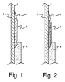
- Fig. 1 shows a part of the lower part of the furnace of a steam boiler, such as a circulating fluidized bed boiler.
- the furnace wall 3 is a so-called water wall, i.e. the wall is formed by water pipes 3 circulating the furnace, which pipes are typically manufactured of non-alloy or low alloy steel.
- the lower part of the furnace comprises a shield refractory 4 (often a refractory or the like).
- a shield structure 1,2 is formed on the inner surface of the furnace wall 3 in order to shield the inner surface above the refractory 4 from the erosion caused by suspension flows.
- the shield structure in question comprises at least a first zone 1 and a second zone 2, whose erosion-resistance properties differ from each other.
- the coating 1 of the first zone has such properties that a form eroding the wall 3 is not formed at the end point of the coating.
- the properties of the material of the second zone 2 in turn, prevent the shield structure from eroding excessively.
- the second zone 2 is a certain type of a hard coating.
- the first zone is less erosion-resistant than the second zone.
- the first zone 1 is allowed to erode during use. By suitably selecting the material of the first zone 1, it is possible to repair the first zone, if necessary, for example by spraying or welding.
- the first zone 1 is located at least partly above the second zone 2 in the direction of the furnace wall 3.
- a property of the coating such as, for example, its chemical composition, changes gradually or continuously when moving from the first zone 1 to the second zone 2.
- Making the zones 1,2 is possible with different techniques.
- a possible way to change the properties of the material is by means of so-called laser technology.
- the properties of the material can be changed by changing the composition of the material and/or by modifying the material.
- a smooth connection of the coating (especially the first zone) to the wall 3 can also be implemented in several ways, such as, for example, by means of coating technology or by machining (for example by grinding).
- Fig. 2 shows another embodiment of the invention, where two different coatings are used partly on top of each other.
- the second, i.e. lower zone 2 is formed of a more erosion-resistant material than the first, i.e. upper zone 1.
- the wall 3 can be coated by hard facing or metal spraying in order to form the second zone 2.
- the first zone 1 is formed by welding or coating in some other manner, advantageously all the up to the shield refractory 4 from above the second zone 2.
- the erosion properties of the material of the first zone 1 correspond substantially to the properties of the furnace wall 3, i.e. the water pipe in the example.
- connection of the first zone 1 to the pipe 3 is formed into such that it does not cause substantial erosion.
- the connection can be implemented in such a manner that the angle between the surfaces of the pipe 3 and the first zone 1 in the direction of the particle flow is formed as small as possible or the connection is implemented as substantially continuous.
Landscapes
- Engineering & Computer Science (AREA)
- Chemical & Material Sciences (AREA)
- Combustion & Propulsion (AREA)
- Mechanical Engineering (AREA)
- General Engineering & Computer Science (AREA)
- Coating By Spraying Or Casting (AREA)
- Fluidized-Bed Combustion And Resonant Combustion (AREA)
Abstract
Description
- The invention relates to a method for shielding the inner surface above the shield refractory of the furnace wall of a circulating fluidized be boiler from erosion caused by suspension flows according to the preamble of the appended
claim 1. In addition, the invention relates to a circulating fluidized bed boiler according to the preamble of the appended claim 8. - A complex suspension flow exists in the furnace of a circulating fluidized bed boiler (CFB boiler). The suspension flow of the furnace consists essentially of an upward flow in the central area of the furnace, where the density of the suspension decreases from the value of 1,000 kg/m3 in the lower part to the density of 3 kg/m3 in the upper part. Particles separate close to the walls from the upward flow along the way in the central area. The speed of the particles is decreased and finally, close to the wall, it turns into a downward flow. The downward particle flow is typically approximately 50...100 mm thick and the thickness of the particle film formed by the flow is at its greatest in the lower parts of the furnace.
- Because of the erosion effect of the suspension flow in the furnace, the water pipes in the furnace walls are shielded with a shield refractory in the points that are prone to erode. Typically, membrane-built water pipes are shielded with a shield refractory that is approximately 50 to 80 mm thick and at approximately the height of 4 to 6 m from the bottom of the furnace.
- Erosion at the end point of the lower part of the furnace is strong if it is not aimed to be prevented by means of any method. The erosion is believed to be caused at least partly by the downward flowing suspension impinging on the edge of the refractory and together with the upward central flow causes a whirl, which tends to erode the wall of the furnace.
- The erosion at the end point of the refractory has been aimed to be prevented by coating the wall (water pipe) above the refractory at the height of 300 to 600 mm with a erosion-resistant coating (a so-called hard coating), whose upper part is aimed to be made as smooth as possible, without a shoulder. The above-mentioned measurements naturally depend on the size and dimensions of the boiler.
- When coating the wall above the refractory with a hard coating, the erosion immediately over the refractory is, however, often so intense that the coatings cannot endure the erosion for long. In addition, during use a small shoulder is formed in the upper part of the coating, for example because of the coating breaking away or the pipe eroding (because the pipe as a softer material erodes faster than the coating). The shoulder causes a point of discontinuity and a whirl in the downward particle flow. Due to the whirl in the particle flow the wall and the pipes in it erode. In other words, known solutions have at least the problem that the pipe and/or coating erodes directly above the refractory, and that the upper end of the coating and the pipe at the corresponding location erode.
- Now a solution has been invented, which essentially decreases the erosion of the wall above the refractory.
- To attain this purpose, the method according to the invention is primarily characterized in what will be presented in the characterizing part of the
independent claim 1. The circulating fluidized bed boiler according to the invention is, in turn, primarily characterized in what will be presented in the characterizing part of the independent claim 8. The other, dependent claims will present some preferred embodiments of the invention. - A basic idea of the invention is that in order to protect the inner surface of the furnace wall of the steam boiler from the erosion caused by the suspension flows, a shield structure is formed on the inner surface of the boiler wall, which structure comprises at least a first zone and a second zone. The erosion-resistance properties of said zones differ form each other.
- In an embodiment of the invention the first zone is located at least partly above the second zone. The coating of the first zone has such properties that an eroding form is not formed at the end point of the coating. The properties of the material of the second zone prevent the point in question from eroding. According to an embodiment, the first zone is less erosion-resistant than the second zone.
- In a solution according to an embodiment of the invention, a property of the coating, such as its chemical composition, changes gradually or continuously when moving from the first zone to the second zone. Manufacturing the zones is possible with different techniques. The properties of the material can be changed by changing the composition of the material and/or by modifying the material. A possible way to change the properties of the material is by means of so-called laser technology. A smooth connection of the coating to the wall can also be implemented in several ways, such as, for example, by means of coating technology or by machining (for example by grinding).
- In another embodiment of the invention two different coatings are used partly on top of each other. The lower zone is formed of a harder material. For example the wall is coated by means of hard facing or metal spraying in order to form a second zone. After this, welding or coating is performed with a softer material above the second zoned advantageously all the way to the refractory. In an advantageous embodiment the connection of the coating to the pipe is formed as continuous. In an advantageous embodiment the erosion properties of the material of the first zone correspond to those of the pipe. Thus, no erosion or formation of a shoulder takes place at that point. In known solutions the formation of a shoulder may be due to either the breaking away of the coating or the fact that the pipe being of a softer material erodes faster than the coating.
- The material of the second zone, i.e. a certain kind of a hard coating, decreases erosion significantly. The firs zone, i.e. the soft coating, is in turn let erode. It can, if necessary, be repaired by adding material, for example, by spraying or welding.
- The structure according to the invention has several advantages. A significant advantage is decrease erosion.
- In some embodiments the invention also enables repairing the coating. In some cases the repairing possibility of the coating is facilitated by the welding possibility.
- In the following, the invention will be described in more detail with reference to the appended principle drawings, in which
- Fig. 1 shows an embodiment according to the invention, and
- Fig. 2 shows another embodiment according to the invention.
- For the sake of clarity, the figures only show the details necessary for understanding the invention. The structures and details that are not necessary for understanding the invention but are obvious for anyone skilled in the art have been omitted from the figures to emphasize the characteristics of the invention. The dimensions of the figures have also been chosen in such a manner that the basic idea of the invention is as apparent as possible in the figures. Thus, the mutual dimensions of the different parts can differ significantly from those in the figures.
- Fig. 1 shows a part of the lower part of the furnace of a steam boiler, such as a circulating fluidized bed boiler. In the example the
furnace wall 3 is a so-called water wall, i.e. the wall is formed bywater pipes 3 circulating the furnace, which pipes are typically manufactured of non-alloy or low alloy steel. Typically the lower part of the furnace comprises a shield refractory 4 (often a refractory or the like). - According to a basic idea of the invention, a
shield structure furnace wall 3 in order to shield the inner surface above therefractory 4 from the erosion caused by suspension flows. The shield structure in question comprises at least afirst zone 1 and asecond zone 2, whose erosion-resistance properties differ from each other. Thecoating 1 of the first zone has such properties that a form eroding thewall 3 is not formed at the end point of the coating. The properties of the material of thesecond zone 2, in turn, prevent the shield structure from eroding excessively. Thesecond zone 2 is a certain type of a hard coating. Advantageously the first zone is less erosion-resistant than the second zone. Thefirst zone 1 is allowed to erode during use. By suitably selecting the material of thefirst zone 1, it is possible to repair the first zone, if necessary, for example by spraying or welding. - As can be seen in Fig. 1, in an embodiment of the invention according to the example the
first zone 1 is located at least partly above thesecond zone 2 in the direction of thefurnace wall 3. In a solution according to an example, a property of the coating, such as, for example, its chemical composition, changes gradually or continuously when moving from thefirst zone 1 to thesecond zone 2. Making thezones wall 3 can also be implemented in several ways, such as, for example, by means of coating technology or by machining (for example by grinding). - Fig. 2, in turn, shows another embodiment of the invention, where two different coatings are used partly on top of each other. The second, i.e.
lower zone 2 is formed of a more erosion-resistant material than the first, i.e.upper zone 1. For example, thewall 3 can be coated by hard facing or metal spraying in order to form thesecond zone 2. After this, thefirst zone 1 is formed by welding or coating in some other manner, advantageously all the up to the shield refractory 4 from above thesecond zone 2. In an advantageous embodiment the erosion properties of the material of thefirst zone 1 correspond substantially to the properties of thefurnace wall 3, i.e. the water pipe in the example. Thus, there is no harmful amount of erosion in the connecting point of thefirst zone 1 and thewall 3, and therefore no formation of a shoulder takes palace either. In an advantageous embodiment the connection of thefirst zone 1 to thepipe 3 is formed into such that it does not cause substantial erosion. For example, the connection can be implemented in such a manner that the angle between the surfaces of thepipe 3 and thefirst zone 1 in the direction of the particle flow is formed as small as possible or the connection is implemented as substantially continuous. By means of the solutions presented above, the problems of prior art can be decrease or substantially removed, such as, for example, that the formation of a shoulder is caused by either the coating breaking away or by that the pipe being a softer material erodes faster than the coating. - By combining, in various ways, the modes and structures disclosed in connection with the different embodiments of the invention presented above, it is possible to produce various embodiments of the invention in accordance with the spirit of the invention. Therefore, the above-presented examples must not be interpreted as restrictive to the invention, but the embodiments of the invention may be freely varied within the scope of the inventive features presented in the claims hereinbelow.
Claims (14)
- A method for shielding the inner surface above the shield refractory (4) of the furnace wall (3) of a circulating fluidized bed boiler from erosion caused by suspension flows, in which method a shield structure is formed on the inner surface of the boiler wall,
characterized in that
at least a first zone (1) and a second zone (2) are formed in the shield structure, the erosion-resistance properties of which zones differ from each other. - The method according to claim 1, characterized in that the shield structure is formed on the surface of the water pipe (3) of the water wall of the boiler.
- The method according to claim 1 or 2, characterized in that the first zone (1) is located at least partly above the second zone (2) in the directi on of the furnace wall (3).
- The method according to any of the preceding claims, characterized in that the first zone (1) is less erosion-resistant than the second zone (2) in operating conditions.
- The method according to any of the preceding claims, characterized in that the first zone (1) and the second zone (2) are formed of different materials.
- The method according to any of the preceding claims 1 to 4, characterized in that the first zone (1) is formed of a first material and the second zone (2) is formed by blending the first material.
- The method according to any of the preceding claims 1 to 4, characterized in that the second zone (2) is formed of a first material and the first zone (1) is formed by blending the first material.
- A circulating fluidized bed boiler, which comprises at least- a furnace,- a shield refractory (4) arranged in the wall (3) of the lower part of the furnace to shield the inner surface from the erosion caused by suspension flows, and- a shield structure, which is located at least partly above the shield refractory (4) on the inner surface of the wall (3) to shield the inner surface above the shield refractory (4) from the erosion caused by suspension flows,characterized in that
the shield structure comprises at least a first zone (1) and a second zone (2), whose erosion-resistance properties differ from each other. - The circulating fluidized bed boiler according to claim 8, characterized in that the shield structure is formed on the surface of the water pipe (3) of the water wall of the boiler.
- The circulating fluidized bed boiler according to claim 8 or 9, characterized in that the first zone (1) is located at least partly above the second zone (2) in the direction of the furnace wall (3).
- The circulating fluidized bed boiler according to any of the preceding claims 8 to 10, characterized in that the first zone (1) is less erosion-resistant than the second zone (2) in operating conditions.
- The circulating fluidized bed boiler according to any of the preceding claims 8 to 11, characterized in that the first zone (1) and the second zone (2) are formed of different materials.
- The circulating fluidized bed boiler according to any of the preceding claims 8 to 11, characterized in that the first zone (1) is formed of a first material and the second zone (2) is formed by blending the first material.
- The circulating fluidized bed boiler according to any of the preceding claims 8 to 11, characterized in that the second zone (2) is formed of a first material and the first zone (1) is formed by blending the first material.
Applications Claiming Priority (1)
| Application Number | Priority Date | Filing Date | Title |
|---|---|---|---|
| FI20045351A FI116541B (en) | 2004-09-24 | 2004-09-24 | Erosion protection of circulating fluidized bed boiler |
Publications (2)
| Publication Number | Publication Date |
|---|---|
| EP1640660A2 true EP1640660A2 (en) | 2006-03-29 |
| EP1640660A3 EP1640660A3 (en) | 2006-04-19 |
Family
ID=33041629
Family Applications (1)
| Application Number | Title | Priority Date | Filing Date |
|---|---|---|---|
| EP05397018A Withdrawn EP1640660A3 (en) | 2004-09-24 | 2005-09-19 | Erosion shielding for a circulating fluidized bed boiler |
Country Status (4)
| Country | Link |
|---|---|
| US (1) | US20060065173A1 (en) |
| EP (1) | EP1640660A3 (en) |
| CA (1) | CA2520697A1 (en) |
| FI (1) | FI116541B (en) |
Cited By (5)
| Publication number | Priority date | Publication date | Assignee | Title |
|---|---|---|---|---|
| DE102009030649A1 (en) * | 2009-06-25 | 2010-12-30 | Rwe Power Ag | Power station boiler for fluidized-bed combustion plant, has boiler wall provide with multiple parts, which exhibit thermal coating as wear protective measure, where thermal coating is partially laid in boiler wall |
| CN103604118A (en) * | 2013-11-20 | 2014-02-26 | 七台河宝泰隆煤化工股份有限公司 | Abrasion resistant device of boiler water wall tube |
| EP2436980A3 (en) * | 2010-10-04 | 2016-01-13 | Spartherm Feuerungstechnik GmbH | Device for burning solid fuels |
| JP2016183809A (en) * | 2015-03-26 | 2016-10-20 | 住友重機械工業株式会社 | Fluidized bed reactor |
| WO2018158497A1 (en) | 2017-03-03 | 2018-09-07 | Sumitomo SHI FW Energia Oy | Watertube panel portion and a method of manufacturing a watertube panel portion in a fluidized bed reactor |
Families Citing this family (3)
| Publication number | Priority date | Publication date | Assignee | Title |
|---|---|---|---|---|
| EP2180252B1 (en) * | 2008-10-24 | 2016-03-23 | L'Air Liquide Société Anonyme pour l'Etude et l'Exploitation des Procédés Georges Claude | Method for injecting ballast into an oxycombustion boiler |
| CN101701706B (en) * | 2009-11-20 | 2012-11-14 | 无锡华光锅炉股份有限公司 | Improved anti-abrasion structure at wall-through place of water-cooling wall and screen-type heating surface |
| DE102010017087B4 (en) * | 2010-05-26 | 2013-08-22 | Schott Ag | fireplace |
Family Cites Families (7)
| Publication number | Priority date | Publication date | Assignee | Title |
|---|---|---|---|---|
| US5091156A (en) * | 1989-02-13 | 1992-02-25 | A. Ahlstrom Corporation | Waterwalls in a fluidized bed reactor |
| US5063028A (en) * | 1990-05-18 | 1991-11-05 | Mobil Oil Corporation | Process and apparatus for regeneration of FCC catalyst |
| US5072696A (en) * | 1990-12-11 | 1991-12-17 | Foster Wheeler Energy Corporation | Furnace temperature control method for a fluidized bed combustion system |
| US5239945A (en) * | 1991-11-13 | 1993-08-31 | Tampella Power Corporation | Apparatus to reduce or eliminate combustor perimeter wall erosion in fluidized bed boilers or reactors |
| FI96541C (en) * | 1994-10-03 | 1996-07-10 | Ahlstroem Oy | Device on a wall and method for coating the wall |
| WO1997003322A1 (en) * | 1995-07-13 | 1997-01-30 | Foster Wheeler Energia Oy | Erosion resistant wall assembly |
| US6044805A (en) * | 1999-05-06 | 2000-04-04 | The Babcock & Wilcox Company | Wall protection from downward flowing solids |
-
2004
- 2004-09-24 FI FI20045351A patent/FI116541B/en active IP Right Grant
-
2005
- 2005-09-19 EP EP05397018A patent/EP1640660A3/en not_active Withdrawn
- 2005-09-22 CA CA002520697A patent/CA2520697A1/en not_active Abandoned
- 2005-09-23 US US11/232,950 patent/US20060065173A1/en not_active Abandoned
Cited By (7)
| Publication number | Priority date | Publication date | Assignee | Title |
|---|---|---|---|---|
| DE102009030649A1 (en) * | 2009-06-25 | 2010-12-30 | Rwe Power Ag | Power station boiler for fluidized-bed combustion plant, has boiler wall provide with multiple parts, which exhibit thermal coating as wear protective measure, where thermal coating is partially laid in boiler wall |
| DE102009030649B4 (en) * | 2009-06-25 | 2011-04-28 | Rwe Power Ag | Power plant boilers, in particular for fluidized bed combustion plants with a thermal coating as wear protection measure and method for the thermal coating of power plant boilers as a wear protection measure |
| EP2436980A3 (en) * | 2010-10-04 | 2016-01-13 | Spartherm Feuerungstechnik GmbH | Device for burning solid fuels |
| CN103604118A (en) * | 2013-11-20 | 2014-02-26 | 七台河宝泰隆煤化工股份有限公司 | Abrasion resistant device of boiler water wall tube |
| JP2016183809A (en) * | 2015-03-26 | 2016-10-20 | 住友重機械工業株式会社 | Fluidized bed reactor |
| WO2018158497A1 (en) | 2017-03-03 | 2018-09-07 | Sumitomo SHI FW Energia Oy | Watertube panel portion and a method of manufacturing a watertube panel portion in a fluidized bed reactor |
| US10323842B2 (en) | 2017-03-03 | 2019-06-18 | Sumitomo SHI FW Energia Oy | Watertube panel portion and a method of manufacturing a watertube panel portion in a fluidized bed reactor |
Also Published As
| Publication number | Publication date |
|---|---|
| FI116541B (en) | 2005-12-15 |
| US20060065173A1 (en) | 2006-03-30 |
| CA2520697A1 (en) | 2006-03-24 |
| FI20045351A0 (en) | 2004-09-24 |
| EP1640660A3 (en) | 2006-04-19 |
Similar Documents
| Publication | Publication Date | Title |
|---|---|---|
| EP1640660A2 (en) | Erosion shielding for a circulating fluidized bed boiler | |
| US10450831B2 (en) | Choke assembly | |
| DE69507039T2 (en) | ARRANGEMENT IN A WALL AND METHOD FOR COATING A WALL | |
| US4641864A (en) | Wear resistant pipe bend for slurry transport | |
| JPS58500910A (en) | Small radius of curvature, low wear elbow tube | |
| KR101384019B1 (en) | Continuous casting method for molten metal | |
| JP4508110B2 (en) | Immersion nozzle for continuous casting and continuous casting method using the same | |
| CN1042143C (en) | Melting furnace with gas injection | |
| CA2046587C (en) | Waterwalls in a fluidized bed reactor | |
| JP2024506440A (en) | Protection of valve parts from erosion | |
| CN100549518C (en) | Grid nozzle of fluidized bed reactor | |
| CN1131453A (en) | Device to prevent underwater vortex at pump inlet | |
| JP5205883B2 (en) | Converter bottom blowing gas distribution device | |
| CN110792868A (en) | Erosion-resistant pipeline elbow with V-shaped ribs | |
| JP2005058872A (en) | Method and apparatus for collecting particles in high-temperature gas | |
| US6175584B1 (en) | Aspiration system to reduce the losses of fine materials and powders from an electric arc furnace | |
| JP3524507B2 (en) | Steel continuous casting method | |
| CN110582670B (en) | Water panel section and method for manufacturing water panel section in fluidized bed reactor | |
| FI94984C (en) | Fluidized bed reactor water walls | |
| JP2000018199A (en) | Vortex generation prevention device for pump suction tank | |
| DE69000911T2 (en) | Fluid bed reactor with water dividers. | |
| CN1252412C (en) | Fluidized bed boiler combustion room with anti-abration structure | |
| CN115059622B (en) | A submersible sewage pump with sand control function | |
| JPH04220148A (en) | Molten steel supplying nozzle | |
| KR102441034B1 (en) | Slag mixing prevention method and vortex prevention body when molten steel is tapped |
Legal Events
| Date | Code | Title | Description |
|---|---|---|---|
| PUAI | Public reference made under article 153(3) epc to a published international application that has entered the european phase |
Free format text: ORIGINAL CODE: 0009012 |
|
| PUAL | Search report despatched |
Free format text: ORIGINAL CODE: 0009013 |
|
| AK | Designated contracting states |
Kind code of ref document: A2 Designated state(s): AT BE BG CH CY CZ DE DK EE ES FI FR GB GR HU IE IS IT LI LT LU LV MC NL PL PT RO SE SI SK TR |
|
| AX | Request for extension of the european patent |
Extension state: AL BA HR MK YU |
|
| AK | Designated contracting states |
Kind code of ref document: A3 Designated state(s): AT BE BG CH CY CZ DE DK EE ES FI FR GB GR HU IE IS IT LI LT LU LV MC NL PL PT RO SE SI SK TR |
|
| AX | Request for extension of the european patent |
Extension state: AL BA HR MK YU |
|
| 17P | Request for examination filed |
Effective date: 20060925 |
|
| AKX | Designation fees paid |
Designated state(s): AT BE BG CH CY CZ DE DK EE ES FI FR GB GR HU IE IS IT LI LT LU LV MC NL PL PT RO SE SI SK TR |
|
| RAP1 | Party data changed (applicant data changed or rights of an application transferred) |
Owner name: METSO POWER OY |
|
| STAA | Information on the status of an ep patent application or granted ep patent |
Free format text: STATUS: THE APPLICATION IS DEEMED TO BE WITHDRAWN |
|
| 18D | Application deemed to be withdrawn |
Effective date: 20100401 |