EP1640571A1 - Oily supply device for engine - Google Patents
Oily supply device for engine Download PDFInfo
- Publication number
- EP1640571A1 EP1640571A1 EP05020471A EP05020471A EP1640571A1 EP 1640571 A1 EP1640571 A1 EP 1640571A1 EP 05020471 A EP05020471 A EP 05020471A EP 05020471 A EP05020471 A EP 05020471A EP 1640571 A1 EP1640571 A1 EP 1640571A1
- Authority
- EP
- European Patent Office
- Prior art keywords
- oil
- pump
- system portion
- passage
- valve
- Prior art date
- Legal status (The legal status is an assumption and is not a legal conclusion. Google has not performed a legal analysis and makes no representation as to the accuracy of the status listed.)
- Granted
Links
- 239000003921 oil Substances 0.000 claims abstract description 511
- 238000005461 lubrication Methods 0.000 claims abstract description 95
- 238000001816 cooling Methods 0.000 claims abstract description 78
- 239000010705 motor oil Substances 0.000 claims abstract description 24
- 238000007599 discharging Methods 0.000 claims abstract description 10
- 230000000903 blocking effect Effects 0.000 claims abstract description 6
- 238000011144 upstream manufacturing Methods 0.000 claims description 5
- 238000010276 construction Methods 0.000 description 14
- 238000010586 diagram Methods 0.000 description 7
- 239000003595 mist Substances 0.000 description 4
- 239000000446 fuel Substances 0.000 description 2
- 238000002347 injection Methods 0.000 description 2
- 239000007924 injection Substances 0.000 description 2
- 239000000463 material Substances 0.000 description 2
- 238000005299 abrasion Methods 0.000 description 1
- 239000000498 cooling water Substances 0.000 description 1
- 230000007423 decrease Effects 0.000 description 1
- 238000005265 energy consumption Methods 0.000 description 1
- 230000002349 favourable effect Effects 0.000 description 1
- 230000001050 lubricating effect Effects 0.000 description 1
- 239000000203 mixture Substances 0.000 description 1
- XLYOFNOQVPJJNP-UHFFFAOYSA-N water Substances O XLYOFNOQVPJJNP-UHFFFAOYSA-N 0.000 description 1
Images

Classifications
-
- F—MECHANICAL ENGINEERING; LIGHTING; HEATING; WEAPONS; BLASTING
- F01—MACHINES OR ENGINES IN GENERAL; ENGINE PLANTS IN GENERAL; STEAM ENGINES
- F01M—LUBRICATING OF MACHINES OR ENGINES IN GENERAL; LUBRICATING INTERNAL COMBUSTION ENGINES; CRANKCASE VENTILATING
- F01M1/00—Pressure lubrication
- F01M1/12—Closed-circuit lubricating systems not provided for in groups F01M1/02 - F01M1/10
-
- F—MECHANICAL ENGINEERING; LIGHTING; HEATING; WEAPONS; BLASTING
- F01—MACHINES OR ENGINES IN GENERAL; ENGINE PLANTS IN GENERAL; STEAM ENGINES
- F01M—LUBRICATING OF MACHINES OR ENGINES IN GENERAL; LUBRICATING INTERNAL COMBUSTION ENGINES; CRANKCASE VENTILATING
- F01M1/00—Pressure lubrication
- F01M1/02—Pressure lubrication using lubricating pumps
-
- F—MECHANICAL ENGINEERING; LIGHTING; HEATING; WEAPONS; BLASTING
- F01—MACHINES OR ENGINES IN GENERAL; ENGINE PLANTS IN GENERAL; STEAM ENGINES
- F01M—LUBRICATING OF MACHINES OR ENGINES IN GENERAL; LUBRICATING INTERNAL COMBUSTION ENGINES; CRANKCASE VENTILATING
- F01M1/00—Pressure lubrication
- F01M1/16—Controlling lubricant pressure or quantity
-
- F—MECHANICAL ENGINEERING; LIGHTING; HEATING; WEAPONS; BLASTING
- F01—MACHINES OR ENGINES IN GENERAL; ENGINE PLANTS IN GENERAL; STEAM ENGINES
- F01M—LUBRICATING OF MACHINES OR ENGINES IN GENERAL; LUBRICATING INTERNAL COMBUSTION ENGINES; CRANKCASE VENTILATING
- F01M5/00—Heating, cooling, or controlling temperature of lubricant; Lubrication means facilitating engine starting
- F01M5/002—Cooling
-
- F—MECHANICAL ENGINEERING; LIGHTING; HEATING; WEAPONS; BLASTING
- F01—MACHINES OR ENGINES IN GENERAL; ENGINE PLANTS IN GENERAL; STEAM ENGINES
- F01M—LUBRICATING OF MACHINES OR ENGINES IN GENERAL; LUBRICATING INTERNAL COMBUSTION ENGINES; CRANKCASE VENTILATING
- F01M1/00—Pressure lubrication
- F01M1/12—Closed-circuit lubricating systems not provided for in groups F01M1/02 - F01M1/10
- F01M2001/123—Closed-circuit lubricating systems not provided for in groups F01M1/02 - F01M1/10 using two or more pumps
Definitions
- the present invention relates to an oil supply device for an engine. More particularly, the present invention pertains to an oil supply device for an engine, which supplies oil to lubrication system portions and cooling system portions of the engine.
- a known oil supply device for an engine described in JPH04 (1992)-132414U includes a main oil pump (i.e., a first pump) and a motor driven oil pump (i.e., a second pump).
- a destination of oil from each pump is changed by appropriately switching oil passages from the both pumps on the basis of engine rotation speed.
- the first pump and the second pump are arranged in parallel from each other relative to a destination of oil, and oil supplied from the oil pumps is used mainly for hydraulic pressure actuation.
- a first pump and a second pump are arranged in series relative to a destination of oil.
- oil sucked from an oil reservoir is discharged by the first pump to the second pump side, and the second pump discharges the oil discharged from the first pump to the destination of the oil.
- Lubrication system portions such as a cam and a cam chain, which require supply of oil for lubrication and cooling system portions such as a piston, which require supply of oil for cooling require oil supply at engine in addition to the aforementioned portions related to the hydraulic pressure actuation.
- the both pumps should be high output pumps when it is necessary to supply oil by high pressure relative to the destination of the oil.
- the second pump cannot suck oil unless the first pump is operated, and thus the second pump cannot supply the oil to the destination of the oil.
- oil cannot be supplied from the second pump to the destination of the oil until the first pump sufficiently sucks oil and discharge the oil to the second pump at an engine start.
- the present invention provides an oil supply device for an engine for supplying oil to a lubrication system portion and a cooling system portion of an engine, characterized by a first oil suction passage in communication with an oil reservoir which reserves oil, a second oil suction passage in communication with the oil reservoir, a first pump for sucking oil from the first oil suction passage by means of rotation of crankshaft of the engine and for discharging the sucked oil, a second pump arranged in series with the first pump for controlling switching On-Off operation, the second pump configured to be supplied with oil discharged from the first pump and introduced from the second oil suction passage for sucking and discharging oil from at least one of the first pump and the second oil suction passage, a check valve for blocking oil circulation from the second pump to the first pump and from the second oil suction passage to the first pump, a first oil passage diverged between the check valve and the first pump and extended to the lubrication system portion, a second oil passage extended from the second pump to the cooling system portion, a third
- the supply volume control means can change oil supply volume from the oil pump to the lubrication system portion, to the cooling system portion, or to the lubrication system portion and the cooling system portion in accordance with operational state of the engine, for example, at least one of change of oil temperature of the engine, engine rotation speed, and engine load.
- the oil pump of the oil supply device includes the first pump for utilizing rotation of the crankshaft of the engine and the second pump which controls to switch operation of the oil supply device.
- the first pump is configured to output torque to easily discharge oil with relatively high viscosity, and can supply oil to the lubrication system portion even when oil temperature is low and oil viscosity is high.
- On-Off of the operation of the second pump 2 in accordance with an operational state of the engine, optimum volume of oil can be supplied to the lubrication portion and to the cooling system portion in accordance with operational state of the engine.
- engine efficiency can be increased by preventing oil supply to unnecessary portion and by supplying appropriate volume of oil to necessary portions.
- the first valve is provided to block circulation of oil from the first oil passage to the second oil passage.
- the second pump is arranged in series with the first pump, and is arranged to suck oil discharged from the first pump, oil pressure at suction side of the second pump assumes oil pressure supplied from the first pump, and oil can be sucked with less power than power for sucking oil by the second pump alone. Accordingly, output of the second pump per se can be reduced and the second pump can be reduced in size.
- the second pump can output oil discharged from the first pump by further increasing the pressure with less power, and thus, it is advantageous when the second pump supplies oil to a destination of the oil such as an oil jet which requires large volume and high pressured oil.
- the second pump alone can suck oil from the second oil suction passage even when oil is not filled up in the first pump and piping because the first pump has not sufficiently sucked oil discharged from the first pump through the first oil suction passage, for example, at immediately after the engine start.
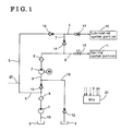
- Fig. 1 is a schematic diagram of an oil supply device according to a first embodiment of the present invention.
- Fig. 2 is a partial schematic diagram of an oil supply device according to a second embodiment of the present invention.
- Fig. 3 is a partial schematic diagram of an oil supply device according to a third embodiment of the present invention.
- Fig. 4 is a partial schematic diagram of an oil supply device according to a fourth embodiment of the present invention.
- Fig. 5 is a partial schematic diagram of an oil supply device according to a fifth embodiment of the present invention.
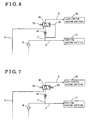
- Fig. 6 is a partial schematic diagram of an oil supply device according to a sixth embodiment of the present invention.
- Fig. 7 is a partial schematic diagram of an oil supply device according to a seventh embodiment of the present invention.
- an oil supply device for an engine includes an oil supply circuit which includes a lubrication system portion 10 where oil for lubrication is supplied in the engine and a cooling system portion 11 where the oil for cooling is supplied.
- the lubrication system portion 10 includes a cam shower for showering oil for lubrication to a cam, and a chain jet for jetting oil for oil to a cam chain, or the like.
- the cooling system portion 11, for example, includes a piston jet for jetting cooling oil to a piston.
- the oil supply circuit oil is supplied to the lubrication system portion 10 and the cooling system portion 11 from either a first oil reservoir 3 or a second oil reservoir 4. More particularly, the oil supply circuit includes a first pump 1 and a second pump 2 for discharging oil to the lubrication system portion 10 and the cooling system portion 11 by sucking oil from the first oil reservoir 3 and the second oil reservoir 4. As shown in Fig. 1, in order to promptly supply the oil to the second pump 2, it is preferable that the second oil reservoir 4 provided separately from the first oil reservoir 3 is arranged in the vicinity of the second pump 2. However, the first oil reservoir 3 and the second oil reservoir 4 may be provided unitarily.
- a mechanical oil pump driven by rotation of a crankshaft of an engine serves as the first pump 1.
- An electric oil pump whose output oil volume and ON-OFF operation are controlled by controlling actuation of a motor M serves as the second pump 2.
- discharged volume of oil at the first pump 1 can be compensated by operating the second pump when the first pump is not sufficiently functioned, for example, at immediately after the engine start. Further, oil can be supplied to the lubrication portion 10 by operating the second pump 2 even before the engine start.
- the second pump allows to set the first pump to have less oil discharging performance. Accordingly, the first pump, which is the mechanical oil pump, is reduced in size and friction of the engine can be declined.
- the first pump 1 is connected to a first oil suction passage 18 for sucking oil from the first oil reservoir 3, and the oil sucked from the first oil reservoir 3 is discharged from the first pump 1 to flow in a first oil filter 8.
- the oil passes through the first oil filter 8 so that foreign materials are removed from the oil and is supplied to the lubrication system portion 10 through the first oil passage 5.
- the second pump 2 is actuated, the oil which has passed through the first oil filter 8 is sucked to be introduced to a second oil passage 6, and is discharged from the second pump 2 to flow in the second oil filter 9.
- the oil passes through the second oil filter 9 so that foreign materials are removed from the oil and is supplied to the cooling system portion 11 or to the cooling system portion 11 and the lubrication system portion 10 through the second oil passage 6.
- the second pump 2 sucks the oil which has passed through the first oil filter 8 to discharge to the second oil passage 6 when the first pump 1 is actuated.
- the second pump 2 pumps oil from the first oil reservoir 3 through the first pump 1.
- oil is sucked from the second oil reservoir 4 which is provided separately from the first oil reservoir 3 through a second oil suction passage 19.
- the oil supply device includes a check valve 13 provided at the first pump 1 side relative to a connecting point between the second oil passage 6 and the second oil suction passage 19 in order to prevent oil sucked by the second oil pump 2 from flowing in reverse to the first pump 1 side. Further, the oil supply device also includes a check valve 12 on the second oil suction passage 19 in order to prevent the oil supplied from the first pump 1 to the second pump 2 from flowing in reverse to the second oil reservoir 4 side. With the construction of the embodiment of the present invention, the second pump 2 can compensate the first pump 1 at any timing.
- the second pump 2 can be reduced in size and the output from the second pump per se can be reduced.
- the construction of the embodiment of the present invention is particularly advantageous for a case where the second pump 2 supplies oil to the cooling system portion 11 such as the oil jet where large volume and high pressured oil is required to be supplied.
- first oil suction passage 18 and the second oil suction passage 19 are arranged in parallel each other relative to the second pump 2, oil introduced from the first oil suction passage 18 and discharged from the first pump 1 and oil introduced from the second oil suction passage 19 is supplied to the second pump 2. Accordingly, for example, the second pump 2 alone can suck the oil from the second oil suction passage 19 provided in parallel to the first oil suction passage 18 to discharge appropriate volume of oil even when the first pump 1 is not filled up with the oil because the first pump 1 has not sufficiently sucked oil from the first oil suction passage 18, for example, at immediately after the engine start.
- oil filters may be provided at an end portion of the first oil suction passage 18 for sucking the oil from the first oil reservoir 3 and at an end portion of the second oil suction passage 19 for sucking the oil from the second oil reservoir 4.
- a third oil passage 7 for establishing the communication between the first oil passage 5 extended from the first pump 1 to the lubrication system portion 10 and the second oil passage 6 extended from the second pump 2 to the cooling system portion 11 is provided between the first oil passage 5 and the second oil passage 6.
- a first valve 14 e.g., a check valve
- a second valve 16 for allowing oil circulation only towards the lubrication system portion 10 is provided on the first oil passage 5 at upstream side relative to a connection point between the first oil passage 5 and the third oil passage 7.
- a third valve 17 (e.g., stop valve) is provided on the first oil passage5 at downstream side of a connection point of the first oil passages 5 and the third oil passage 7 for allowing oil circulation when oil pressure is lower than a predetermined pressure and oil temperature is lower than a predetermined temperature and for stopping oil circulation when oil pressure is equal to or higher than a predetermined pressure and oil temperatures is equal to or lower than a predetermined temperature.
- a predetermined temperature and a predetermined pressure are determined in accordance with engine characteristics and parts of the engine, or the like.
- a fourth oil passage 20 is diverged from the first oil passage 5 at upstream side relative to the second valve 16 for supplying oil to other portions such as a crankshaft bearing portion and a camshaft bearing portion, or the like.
- a fourth valve 15 which adjusts oil volume to the cooling system portion 11 is provide on the second oil passage 6 at downstream side of a connection point between the second oil passage 6 and the third oil passage 7.
- opening degree of the fourth valve 4 By controlling opening degree of the fourth valve 4, a destination and volume of oil to be supplied, the oil being discharged from the second pump 2 and circulated in the second oil passage 6 can be controlled.
- oil which is discharged from the second pump 2 and circulated in the second oil passage 6 is supplied only to the lubrication system portion 10 through the third oil passage 7 when the fourth valve 15 is closed.
- the fourth valve 15 When the fourth valve 15 is open, oil can be distributed to the lubrication system portion 10 and the cooling system portion 11.
- the oil supply device includes an electronic control unit (ECU) 21 for detecting and outputting control signal of an engine rotation speed, a load signal of an engine, an engine oil temperature, and a water temperature of cooling water.
- ECU 21 for detecting and outputting control signal of an engine rotation speed, a load signal of an engine, an engine oil temperature, and a water temperature of cooling water.
- Control signal from the ECU 21 is transmitted to the motor M and the fourth valve 15, and operation of the motor M and opening degree of the fourth valve 15 are controlled.
- the ECU 21 serving as a supply volume control means conducts a supply volume changing control for changing oil supply volume from the second pump 2 to the lubrication system portion 10, to the cooling system portion 11, or to the lubrication system portion 10 and the cooling system portion 11 in accordance with changes of at least one of engine oil temperature, engine rotation speed, and engine load.
- a control for opening degree of the fourth valve 15 and a control for the operation of the motor M by the ECU 21 will be explained as follows.
- Oil supply to the cooling system portion is, first, explained with reference to Table 1.
- oil for cooling is not supplied to the cooling system portion 11 in order to avoid needless cooling of the cooling system portion 11 (i.e., corresponding to A and C in Table 1).
- the oil is supplied to the lubrication system portion 10 through the first oil passage 5 from the first pump 1, the oil is not supplied to the cooling system portion 11 from the first oil passage 5 through the third oil passage 7 because of the first valve 14 provided at the third oil passage 7.
- the cooling system portion 11 exposed to thermally severe environment is cooled (corresponding to D in Table 1). Because the viscosity of oil is low, in this case, the ECU 21 supplies oil to the cooling system portion 11 by the second pump 2 which can control operation of the oil supply device and discharged oil volume, and sets the fourth valve 15 at a predetermined opening degree. Thresholds for the engine rotation speed and engine load when the second pump 2 is operated is set in accordance with an engine characteristics and characteristics of engine parts.
- the ECU 21 supplies oil to the lubrication system portion 10 by the first pump 1 which is a mechanical oil pump which enables to output larger torque and not by the second pump 2 which is an electric oil pump considering high viscosity of the oil.
- oil viscosity assumes lower and spattered volume of oil (amount of oil mist) is increased, in this case, accordingly, it is not necessary to supply oil for lubrication to the lubrication system portion 10 (i.e., corresponding to H in Table 1).
- the ECU 21 serving as a supply volume control means conducts a supply volume change control for increasing oil supply to the cooling system portion 11 in accordance with an increase of engine load and engine rotation speed (i.e., corresponding to D in Table 1).
- the ECU 21 operates the motor M to operate the second pump 2 (e.g., the electric oil pump) to circulate oil to the second oil passage 6.
- the third valve (stop valve) 17 is closed to stop oil supply to the lubrication system portion 10. Accordingly, oil for cooling is selectively supplied to the cooling system portion 11 to cool the cooling system portion 11.
- the ECU 21 conducts a supply volume change control for reducing oil supply volume to the lubrication system portion 10 in accordance with an increase of an engine rotation speed and engine load. More particularly, when, for example, engine rotation speed and engine load are small at a state where an engine oil temperature is equal to or higher than a predetermined temperature, the ECU 21 supplies oil to the lubrication system portion 10 by operating the second pump 2 serving as the electric oil pump. When engine rotation speed and engine load are increased at a state where an engine oil temperature is equal to or higher than a predetermined temperature, the ECU 21 conducts a control for reducing oil supply volume to the lubrication system portion 10 by closing the third valve 17.
- a second embodiment of the present invention will be explained as follows.
- the first valve 14 i.e., check valve
- the second valve 16 i.e., check valve
- the third valve 17 i.e., stop valve
- a third valve 27 may be provided instead of the stop valve.
- the ECU 21 commands to open the third valve 27 when supplying oil for lubrication to the lubrication system portion 10 by the first pump 1 and when supplying oil for lubrication to the lubrication system portion 10 by the second pump 2. Further, the ECU 21 commands to close the third valve 27 and to open the fourth valve 15 so that oil is not supplied to the lubrication system portion 10 when supplying oil for cooling only to the cooling system portion 11 by the second pump 2.
- Other construction of the oil supply device according to the second embodiment is common to the first embodiment, and thus explanation thereof is not repeated.
- a third valve 27 i.e., a opening and closing valve
- a third valve 27 is provided on the first oil passage 5 at the upstream side of the connection point between the first oil passage 5 and the third oil passage 7 instead of the check valve
- a third valve 27 i.e., opening and closing valve
- the first valve 14 shown in Fig. 1 is not provided.
- the ECU 21 commands to open the second valve 26 and the third valve 27 and to close the fourth valve 15 for supplying oil for lubrication only to the lubrication system portion 10 by the first pump 1.
- the ECU 21 commands to open the third valve 27 and to close the fourth valve 15 and the second valve 26 for supplying oil only to the lubrication system portion 10 by the second pump 2.
- the ECU 21 commands to open the fourth valve 15 and to close the second valve 26 and the third valve 27 for supplying oil for cooling only to the cooling system portion 11 by the second pump 2.
- the ECU 21 also commands to close the second valve 26 and to open the fourth valve 15 and the third valve 27 for supplying oil for lubrication to the lubrication system portion 10 by the second pump 2 and for supplying oil for cooling to the cooling system portion 11.
- oil supply volume to the lubrication system portion 10 and the cooling system portion 11 can be optimally adjusted in accordance with operational state of the engine.
- Other construction of the oil supply device according to the third embodiment is common to the first embodiment, and thus explanation thereof is not repeated.
- a fourth embodiment of the present invention will be explained as follows.
- the first valve 14 shown in Fig. 1 is not provided on the third oil passage 7.
- the ECU 21 commands to close the fourth valve 15 when supplying oil for lubrication only to the lubrication system portion 10 using either the both of the first pump 1 and the second pump 2 or either one of the first pump 1 or the second pump 2.
- Other construction of the oil supply device according to the fourth embodiment is common to the first embodiment, and thus explanation thereof is not repeated.
- a fifth embodiment of the present invention will be explained as follows.
- the third valve 27 i.e., opening and closing valve
- the first valve 14 is not provided on the third oil passage 7.
- oil can be circulated freely between the first oil passage 5 and the second oil passage 6. Accordingly, oil volume supplied to the lubrication system portion 10 and the cooling system portion 11 is controlled by constantly adjusting the third valve 27 and the fourth valve 15.
- the ECU 21 commands to open the third valve 27 and to close the fourth valve 15 when supplying oil for lubrication only to the lubrication system portion 10 using either the both of the first pump 1 and the second pump 2 or either one of the first pump 1 or the second pump 2. Further, when supplying oil for cooling only to the cooling system portion 11, the fourth valve 15 is opened and the third valve 27 is closed. When supplying oil to the lubrication system portion 10 and the cooling system portion 11, opening degree of the fourth valve 15 and the third valve 27 are adjusted.
- a sixth embodiment of the present invention will be explained with reference to Fig. 6 as follows.
- plural check valves and stop valves applied in the first embodiment for supplying oil are replaced with a oil passage switching valve 30 operated by the oil pressure.
- the number of parts can be reduced.
- Operation of the oil supply device according to the sixth embodiment of the present invention is as follows. First, when the ECU 21 stops the second pump 2, operational oil is supplied to the lubrication system portion 10 from the first pump 1. The ECU 21 operates the second pump 2 with low pressure where oil discharged at low pressure when engine rotation speed is low and an engine oil temperature is high.
- oil pressure from the second pump 2 affects an oil pressure actuation portion 33, and moves a spool valve biased by the spring 32 to the left of Fig. 6, and operation oil from the second pump 2 is supplied to the lubrication system portion 10.
- the ECU 21 operates the second pump 2 with high pressure when an engine rotation speed is high and an engine oil temperature is high. Accordingly, when the second pump 2 operates to discharge high pressured oil, an adjusting pressure valve 31 is closed at a state where the spool valve is moved to the left in Fig. 6 by the oil pressure from the second pump 2, and operational oil from the second pump 2 is supplied to the cooling system portion 11.
- Other construction of the oil supply device according to the sixth embodiment is common to the first embodiment, and thus explanation thereof is not repeated.
- a seventh embodiment of the present invention will be explained with reference to Fig. 7.
- the oil pressure actuation portion 33 according to the sixth embodiment is replaced with a shape memory spring 43.
- An operation of the oil supply device according to the seventh embodiment of the present invention is as follows. First, when the ECU 21 stops the second pump 2, operational oil is supplied from the first pump 1 to the lubrication system portion 10. The ECU 21 operates the second pump 2 with low pressure for discharging oil when engine rotation speed is low and an engine oil temperature is high. As a result, the shape memory spring 43 is expanded by oil temperature of the operational oil, the spool valve biased by a spring 32 is moved to the left in Fig. 7, and operational oil from the second pump 2 is supplied to the lubrication system portion 10.
- the ECU 21 operates the second pump 2 with high pressure to discharge high-pressured oil when engine rotation speed is high and an engine oil temperature is high. Accordingly, when the second pump 2 is operated at high pressure, because the shape memory spring 43 is expanded at the spool valve, the adjusting pressure valve 31 is closed at a state where the spool valve is moved to the left by the oil pressure from the second pump 2, and operational oil from the second pump 2 is supplied to the cooling system portion 11.
- the supply volume control means can change oil supply volume from the oil pump to the lubrication system portion, to the cooling system portion, or to the lubrication system portion and the cooling system portion in accordance with operational state of the engine, for example, at least one of change of oil temperature of the engine, engine rotation speed, and engine load.
- the oil pump of the oil supply device includes the first pump for utilizing rotation of the crankshaft of the engine and the second pump which controls to switch operation of the oil supply device.
- the first pump is configured to output torque to easily discharge oil with relatively high viscosity, and can supply oil to the lubrication system portion even when oil temperature is low and oil viscosity is high.
- On-Off of the operation of the second pump 2 in accordance with an operational state of the engine, optimum volume of oil can be supplied to the lubrication portion and to the cooling system portion in accordance with operational state of the engine.
- engine efficiency can be increased by preventing oil supply to unnecessary portion and by supplying appropriate volume of oil to necessary portions.
- the first valve is provided to block circulation of oil from the first oil passage to the second oil passage.
- the cooling portion is a piston
- a piston bore is not unnecessarily cooled. Accordingly, because warm-up of the engine at the start of the engine is promoted and engine friction is declined promptly, fuel injection volume is reduced, and thus and engine with high thermal efficiency which improves mileage can be obtained.
- the second pump is arranged in series with the first pump, and is arranged to suck oil discharged from the first pump, oil pressure at suction side of the second pump assumes oil pressure supplied from the first pump, and oil can be sucked with less power than power for sucking oil by the second pump alone. Accordingly, output of the second pump per se can be reduced and the second pump can be reduced in size.
- the second pump can output oil discharged from the first pump by further increasing the pressure with less power, and thus, it is advantageous when the second pump supplies oil to a destination of the oil such as an oil jet which requires large volume and high pressured oil.
- the second pump alone can suck oil from the second oil suction passage even when oil is not filled up in the first pump and piping because the first pump has not sufficiently sucked oil discharged from the first pump through the first oil suction passage, for example, at immediately after the engine start.
- the third valve configured to close when pressure of oil discharged from the first pump or the second pump is increased to be equal to or higher than a predetermined pressure is provided at downstream side relative to the connection point between the first oil passage and the third oil passage.
- volume of oil to be supplied and a destination of oil to be supplied which has discharged from the second pump and circulated in the second oil passage can be controlled.
- oil discharged from the second pump and circulated in the second oil passage is supplied only to the lubrication system portion through the third oil passage when the fourth valve is closed.
- the fourth valve When the fourth valve is open, oil discharged from the second pump and circulated in the second oil passage is distributed to the lubrication system portion and the cooling system portion. Accordingly, by controlling opening degree of the fourth valve, oil volume supplied to the lubrication system portion and oil volume supplied to the cooling system portion can be controlled.
- the ECU 21 i.e., supply volume control means
- the ECU 21 may control an opening degree of the fourth valve and opening and closing of the second and the third valves or may control an opening degree of the fourth valve and opening and closing of the third valve.
Landscapes
- Engineering & Computer Science (AREA)
- Mechanical Engineering (AREA)
- General Engineering & Computer Science (AREA)
- Lubrication Of Internal Combustion Engines (AREA)
- Lubrication Details And Ventilation Of Internal Combustion Engines (AREA)
Abstract
Description
- The present invention relates to an oil supply device for an engine. More particularly, the present invention pertains to an oil supply device for an engine, which supplies oil to lubrication system portions and cooling system portions of the engine.
- A known oil supply device for an engine described in JPH04 (1992)-132414U includes a main oil pump (i.e., a first pump) and a motor driven oil pump (i.e., a second pump). According to the known oil supply device, a destination of oil from each pump is changed by appropriately switching oil passages from the both pumps on the basis of engine rotation speed. With the known oil supply device described in JPH04 (1992)-132414U, the first pump and the second pump are arranged in parallel from each other relative to a destination of oil, and oil supplied from the oil pumps is used mainly for hydraulic pressure actuation.
- According to another oil supply device for an engine described in JPH10 (1998)-252434, a first pump and a second pump are arranged in series relative to a destination of oil. With this oil supply device, oil sucked from an oil reservoir is discharged by the first pump to the second pump side, and the second pump discharges the oil discharged from the first pump to the destination of the oil.
- Lubrication system portions such as a cam and a cam chain, which require supply of oil for lubrication and cooling system portions such as a piston, which require supply of oil for cooling require oil supply at engine in addition to the aforementioned portions related to the hydraulic pressure actuation. However, because whether it is necessary to supply oil to the lubrication system portions and the cooling system portions is varied in accordance with temperature of oil and spattered volume of oil (amount of oil mist) and further because there is adequacy of an oil pump used for supplying oil to each portion (e.g., a pump with larger output torque is required when oil viscosity is higher), oil cannot be supplied appropriately to the lubrication system portion and the cooling system portion with known oil supply devices where oil passages are switched on the basis of only the engine rotation speed.
- Further, with the construction of the oil supply device according to JPH04 (1992)-132414U, because the main oil pump and the electric oil pump are arranged in parallel to the destination of the oil, there is an drawback that the both pumps should be high output pumps when it is necessary to supply oil by high pressure relative to the destination of the oil. Further, with the construction of the oil supply device according to JPH10 (1998)-252434, the second pump cannot suck oil unless the first pump is operated, and thus the second pump cannot supply the oil to the destination of the oil. Particularly, there is a drawback that oil cannot be supplied from the second pump to the destination of the oil until the first pump sufficiently sucks oil and discharge the oil to the second pump at an engine start.
- A need thus exists for an oil supply device of an engine, which appropriately supplies oil to a necessary portion.
- In light of the foregoing, the present invention provides an oil supply device for an engine for supplying oil to a lubrication system portion and a cooling system portion of an engine, characterized by a first oil suction passage in communication with an oil reservoir which reserves oil, a second oil suction passage in communication with the oil reservoir, a first pump for sucking oil from the first oil suction passage by means of rotation of crankshaft of the engine and for discharging the sucked oil, a second pump arranged in series with the first pump for controlling switching On-Off operation, the second pump configured to be supplied with oil discharged from the first pump and introduced from the second oil suction passage for sucking and discharging oil from at least one of the first pump and the second oil suction passage, a check valve for blocking oil circulation from the second pump to the first pump and from the second oil suction passage to the first pump, a first oil passage diverged between the check valve and the first pump and extended to the lubrication system portion, a second oil passage extended from the second pump to the cooling system portion, a third oil passage for establishing communication between the first oil passage and the second oil passage, and a supply volume control means for varying oil supply volume to the lubrication system portion, to the cooling system portion, or to the lubrication system portion and the cooling system portion in accordance with a change in at least one of an engine oil temperature, an engine rotation speed, and an engine load.
- According to the present invention, the supply volume control means can change oil supply volume from the oil pump to the lubrication system portion, to the cooling system portion, or to the lubrication system portion and the cooling system portion in accordance with operational state of the engine, for example, at least one of change of oil temperature of the engine, engine rotation speed, and engine load.
- According to the present invention, the oil pump of the oil supply device includes the first pump for utilizing rotation of the crankshaft of the engine and the second pump which controls to switch operation of the oil supply device. The first pump is configured to output torque to easily discharge oil with relatively high viscosity, and can supply oil to the lubrication system portion even when oil temperature is low and oil viscosity is high. By switching On-Off of the operation of the
second pump 2 in accordance with an operational state of the engine, optimum volume of oil can be supplied to the lubrication portion and to the cooling system portion in accordance with operational state of the engine. Thus, because oil supply volume can be changed freely, engine efficiency can be increased by preventing oil supply to unnecessary portion and by supplying appropriate volume of oil to necessary portions. - According to the present invention, the first valve is provided to block circulation of oil from the first oil passage to the second oil passage. By preventing supply of oil at the first oil passage to the cooling system portion, for example, it can be prevented that oil is supplied to the cooling system portion from the first pump at low oil temperature and at low engine rotation speed. As a result, for example, when the cooling portion is a piston, a piston bore is not unnecessarily cooled. Accordingly, because warm-up of the engine at the start of the engine is promoted and engine friction is declined promptly, fuel injection volume is reduced, and thus and engine with high thermal efficiency which improves mileage can be obtained.
- According to the present invention, because the second pump is arranged in series with the first pump, and is arranged to suck oil discharged from the first pump, oil pressure at suction side of the second pump assumes oil pressure supplied from the first pump, and oil can be sucked with less power than power for sucking oil by the second pump alone. Accordingly, output of the second pump per se can be reduced and the second pump can be reduced in size. By arranging the second pump and the first pump in series, the second pump can output oil discharged from the first pump by further increasing the pressure with less power, and thus, it is advantageous when the second pump supplies oil to a destination of the oil such as an oil jet which requires large volume and high pressured oil.
- Further, according to the present invention, because oil discharged from the first pump and oil introduced from the second oil suction passage is supplied to the second pump, the second pump alone can suck oil from the second oil suction passage even when oil is not filled up in the first pump and piping because the first pump has not sufficiently sucked oil discharged from the first pump through the first oil suction passage, for example, at immediately after the engine start.
- The foregoing and additional features and characteristics of the present invention will become more apparent from the following detailed description considered with reference to the accompanying drawings, wherein:
- Fig. 1 is a schematic diagram of an oil supply device according to a first embodiment of the present invention.
- Fig. 2 is a partial schematic diagram of an oil supply device according to a second embodiment of the present invention.
- Fig. 3 is a partial schematic diagram of an oil supply device according to a third embodiment of the present invention.
- Fig. 4 is a partial schematic diagram of an oil supply device according to a fourth embodiment of the present invention.
- Fig. 5 is a partial schematic diagram of an oil supply device according to a fifth embodiment of the present invention.
- Fig. 6 is a partial schematic diagram of an oil supply device according to a sixth embodiment of the present invention.
- Fig. 7 is a partial schematic diagram of an oil supply device according to a seventh embodiment of the present invention.
- Embodiments of an oil supply device for an engine according to the present invention will be explained with reference to illustrations of drawing figures as follows.
- As shown in Fig.1, an oil supply device for an engine according to a first embodiment of the present invention includes an oil supply circuit which includes a
lubrication system portion 10 where oil for lubrication is supplied in the engine and acooling system portion 11 where the oil for cooling is supplied. For example, thelubrication system portion 10 includes a cam shower for showering oil for lubrication to a cam, and a chain jet for jetting oil for oil to a cam chain, or the like. Thecooling system portion 11, for example, includes a piston jet for jetting cooling oil to a piston. - According to this oil supply circuit, oil is supplied to the
lubrication system portion 10 and thecooling system portion 11 from either afirst oil reservoir 3 or asecond oil reservoir 4. More particularly, the oil supply circuit includes afirst pump 1 and asecond pump 2 for discharging oil to thelubrication system portion 10 and thecooling system portion 11 by sucking oil from thefirst oil reservoir 3 and thesecond oil reservoir 4. As shown in Fig. 1, in order to promptly supply the oil to thesecond pump 2, it is preferable that thesecond oil reservoir 4 provided separately from thefirst oil reservoir 3 is arranged in the vicinity of thesecond pump 2. However, thefirst oil reservoir 3 and thesecond oil reservoir 4 may be provided unitarily. - According to the embodiment of the present invention, a mechanical oil pump driven by rotation of a crankshaft of an engine serves as the
first pump 1. An electric oil pump whose output oil volume and ON-OFF operation are controlled by controlling actuation of a motor M serves as thesecond pump 2. By applying the electric oil pump as thesecond pump 2, for example, discharged volume of oil at thefirst pump 1 can be compensated by operating the second pump when the first pump is not sufficiently functioned, for example, at immediately after the engine start. Further, oil can be supplied to thelubrication portion 10 by operating thesecond pump 2 even before the engine start. In that case, because the engine is started at a state where the oil is sufficiently supplied to thelubrication system portion 10, friction at each portion of the engine declines, and abrasion of parts can be prevented. The second pump allows to set the first pump to have less oil discharging performance. Accordingly, the first pump, which is the mechanical oil pump, is reduced in size and friction of the engine can be declined. - The
first pump 1 is connected to a firstoil suction passage 18 for sucking oil from thefirst oil reservoir 3, and the oil sucked from thefirst oil reservoir 3 is discharged from thefirst pump 1 to flow in afirst oil filter 8. The oil passes through thefirst oil filter 8 so that foreign materials are removed from the oil and is supplied to thelubrication system portion 10 through thefirst oil passage 5. When thesecond pump 2 is actuated, the oil which has passed through thefirst oil filter 8 is sucked to be introduced to asecond oil passage 6, and is discharged from thesecond pump 2 to flow in thesecond oil filter 9. The oil passes through thesecond oil filter 9 so that foreign materials are removed from the oil and is supplied to thecooling system portion 11 or to thecooling system portion 11 and thelubrication system portion 10 through thesecond oil passage 6. - The
second pump 2 sucks the oil which has passed through thefirst oil filter 8 to discharge to thesecond oil passage 6 when thefirst pump 1 is actuated. However, for example, when the oil discharge volume from thefirst pump 1 is not sufficiently, for example, at immediately after the engine start, it is not easy that thesecond pump 2 pumps oil from thefirst oil reservoir 3 through thefirst pump 1. Thus, with the construction of the embodiment of the present invention, oil is sucked from thesecond oil reservoir 4 which is provided separately from thefirst oil reservoir 3 through a secondoil suction passage 19. The oil supply device according to the embodiment of the present invention includes acheck valve 13 provided at thefirst pump 1 side relative to a connecting point between thesecond oil passage 6 and the secondoil suction passage 19 in order to prevent oil sucked by thesecond oil pump 2 from flowing in reverse to thefirst pump 1 side. Further, the oil supply device also includes acheck valve 12 on the secondoil suction passage 19 in order to prevent the oil supplied from thefirst pump 1 to thesecond pump 2 from flowing in reverse to thesecond oil reservoir 4 side. With the construction of the embodiment of the present invention, thesecond pump 2 can compensate thefirst pump 1 at any timing. - As foregoing, because the
first pump 1 and thesecond pump 2 are arranged in series so that thesecond pump 2 sucks the oil discharged from thefirst pump 1, hydraulic pressure at suction side of thesecond pump 2 assumes the hydraulic pressure which is supplied from thefirst pump 1, and oil can be sucked with less power than the oil is sucked only by thesecond pump 2. Accordingly, with the construction of the embodiment of the present invention, thesecond pump 2 can be reduced in size and the output from the second pump per se can be reduced. Because thesecond pump 2 can output the oil by further increasing oil pressure of the oil discharged from thefirst pump 1 with smaller power, the construction of the embodiment of the present invention is particularly advantageous for a case where thesecond pump 2 supplies oil to thecooling system portion 11 such as the oil jet where large volume and high pressured oil is required to be supplied. - Further, because the first
oil suction passage 18 and the secondoil suction passage 19 are arranged in parallel each other relative to thesecond pump 2, oil introduced from the firstoil suction passage 18 and discharged from thefirst pump 1 and oil introduced from the secondoil suction passage 19 is supplied to thesecond pump 2. Accordingly, for example, thesecond pump 2 alone can suck the oil from the secondoil suction passage 19 provided in parallel to the firstoil suction passage 18 to discharge appropriate volume of oil even when thefirst pump 1 is not filled up with the oil because thefirst pump 1 has not sufficiently sucked oil from the firstoil suction passage 18, for example, at immediately after the engine start. - Instead of providing the
first oil filter 8 and thesecond oil filter 9, oil filters may be provided at an end portion of the firstoil suction passage 18 for sucking the oil from thefirst oil reservoir 3 and at an end portion of the secondoil suction passage 19 for sucking the oil from thesecond oil reservoir 4. - A
third oil passage 7 for establishing the communication between thefirst oil passage 5 extended from thefirst pump 1 to thelubrication system portion 10 and thesecond oil passage 6 extended from thesecond pump 2 to thecooling system portion 11 is provided between thefirst oil passage 5 and thesecond oil passage 6. A first valve 14 (e.g., a check valve) for blocking an oil circulation from thefirst oil passage 5 to thesecond oil passage 6 through thethird oil passage 7 and for allowing the oil circulation from thesecond oil passage 6 to thefirst oil passage 5 through thethird oil passage 7 is provided on thethird oil passage 7. A second valve 16 (e.g., a check valve) for allowing oil circulation only towards thelubrication system portion 10 is provided on thefirst oil passage 5 at upstream side relative to a connection point between thefirst oil passage 5 and thethird oil passage 7. - Further, a third valve 17 (e.g., stop valve) is provided on the first oil passage5 at downstream side of a connection point of the
first oil passages 5 and thethird oil passage 7 for allowing oil circulation when oil pressure is lower than a predetermined pressure and oil temperature is lower than a predetermined temperature and for stopping oil circulation when oil pressure is equal to or higher than a predetermined pressure and oil temperatures is equal to or lower than a predetermined temperature. A predetermined temperature and a predetermined pressure are determined in accordance with engine characteristics and parts of the engine, or the like. Afourth oil passage 20 is diverged from thefirst oil passage 5 at upstream side relative to thesecond valve 16 for supplying oil to other portions such as a crankshaft bearing portion and a camshaft bearing portion, or the like. - A
fourth valve 15 which adjusts oil volume to thecooling system portion 11 is provide on thesecond oil passage 6 at downstream side of a connection point between thesecond oil passage 6 and thethird oil passage 7. By controlling opening degree of thefourth valve 4, a destination and volume of oil to be supplied, the oil being discharged from thesecond pump 2 and circulated in thesecond oil passage 6 can be controlled. For example, oil which is discharged from thesecond pump 2 and circulated in thesecond oil passage 6 is supplied only to thelubrication system portion 10 through thethird oil passage 7 when thefourth valve 15 is closed. When thefourth valve 15 is open, oil can be distributed to thelubrication system portion 10 and thecooling system portion 11. - The oil supply device according to the embodiment of the present invention includes an electronic control unit (ECU) 21 for detecting and outputting control signal of an engine rotation speed, a load signal of an engine, an engine oil temperature, and a water temperature of cooling water. Control signal from the
ECU 21 is transmitted to the motor M and thefourth valve 15, and operation of the motor M and opening degree of thefourth valve 15 are controlled. - The
ECU 21 serving as a supply volume control means conducts a supply volume changing control for changing oil supply volume from thesecond pump 2 to thelubrication system portion 10, to thecooling system portion 11, or to thelubrication system portion 10 and thecooling system portion 11 in accordance with changes of at least one of engine oil temperature, engine rotation speed, and engine load. Referring to Fig. 1 and Table 1, a control for opening degree of thefourth valve 15 and a control for the operation of the motor M by theECU 21 will be explained as follows.Table 1 Rotation speed / Load Oil temperature Lower than predetermined value Equal to or higher than predetermined value Cooling system portion Lower than predetermined value A: No B: No B: No Yes (electric Equal to or higher than predetermined value C: No D: Yes (electric oil pump) Lubrication system portion Lower than predetermined value E: Yes F: Yes (electric oil pump) l Equal to or higher than predetermined value G: Yes H: No - Oil supply to the cooling system portion is, first, explained with reference to Table 1. When an engine oil temperature is lower than a predetermined temperature, oil for cooling is not supplied to the
cooling system portion 11 in order to avoid needless cooling of the cooling system portion 11 (i.e., corresponding to A and C in Table 1). In this case, even if the oil is supplied to thelubrication system portion 10 through thefirst oil passage 5 from thefirst pump 1, the oil is not supplied to thecooling system portion 11 from thefirst oil passage 5 through thethird oil passage 7 because of thefirst valve 14 provided at thethird oil passage 7. - On the other hand, when an engine oil temperature is equal to or higher than a predetermined temperature and engine rotation speed and engine load is relatively large, the
cooling system portion 11 exposed to thermally severe environment is cooled (corresponding to D in Table 1). Because the viscosity of oil is low, in this case, theECU 21 supplies oil to thecooling system portion 11 by thesecond pump 2 which can control operation of the oil supply device and discharged oil volume, and sets thefourth valve 15 at a predetermined opening degree. Thresholds for the engine rotation speed and engine load when thesecond pump 2 is operated is set in accordance with an engine characteristics and characteristics of engine parts. - When an engine oil temperature is equal to or higher than a predetermined temperature and engine rotation speed and engine load are relatively small, it is not necessary to cool the engine actively. In this case, the oil supply to the
cooling system portion 11 by thesecond pump 2 is stopped (i.e., corresponding to B in Table 1). In this regard, it is necessary to supply oil to thelubrication system portion 10 by operating thesecond pump 2 even when the engine oil temperature is equal to or higher than a predetermined temperature and the engine rotation speed and engine load are at relatively low level. Thus, theECU 21 stops supply of the oil to thecooling system portion 11 by closing thefourth valve 15. - Regarding oil supply to the
lubrication system portion 10 shown in Table 1, when an engine oil temperature is lower than a predetermined temperature, it is favorable to supply oil for lubrication to the lubrication system portion 10 (i.e., corresponding to E and G in Table 1) because oil viscosity is high and spattered volume of the oil is small. In this case, theECU 21 supplies oil to thelubrication system portion 10 by thefirst pump 1 which is a mechanical oil pump which enables to output larger torque and not by thesecond pump 2 which is an electric oil pump considering high viscosity of the oil. - When an engine oil temperature is equal to or higher than a predetermined temperature and engine rotation speed and engine load are relatively small, spattered volume of the oil assumes less whereas the oil viscosity is low. Thus, oil for lubrication is supplied to the
lubrication system portion 10. In this case, because the oil viscosity is low, large torque is not necessary for discharging the oil. TheECU 21 supplies oil to thelubrication system portion 10 by thesecond pump 2, accordingly (i.e., corresponding to F in Table 1). In this regard, volume of oil to be supplied could be much less. Thus, for example, supply pressure of oil to thelubrication system portion 10 is set at lower pressure than supply pressure of oil to thecooling system portion 11. When an engine oil temperature is equal to or higher than a predetermined temperature and engine rotation speed and engine load are relatively large, oil viscosity assumes lower and spattered volume of oil (amount of oil mist) is increased, in this case, accordingly, it is not necessary to supply oil for lubrication to the lubrication system portion 10 (i.e., corresponding to H in Table 1). - More particularly, when an engine oil temperature is equal to or higher than a predetermined temperature, the
ECU 21 serving as a supply volume control means conducts a supply volume change control for increasing oil supply to thecooling system portion 11 in accordance with an increase of engine load and engine rotation speed (i.e., corresponding to D in Table 1). When an engine oil temperature is changed to be equal to or higher than a predetermined temperature at a state where, for example, engine rotation speed is high and engine load is large, theECU 21 operates the motor M to operate the second pump 2 (e.g., the electric oil pump) to circulate oil to thesecond oil passage 6. In this case, because oil temperature and oil pressure are equal to or higher than predetermined values respectively, the third valve (stop valve) 17 is closed to stop oil supply to thelubrication system portion 10. Accordingly, oil for cooling is selectively supplied to thecooling system portion 11 to cool thecooling system portion 11. - Because oil viscosity is declined at a state where an engine oil temperature is equal to or higher than a predetermined temperature, spattered volume of oil (amount of oil mist) is increased at the
lubrication system portion 10, for example, when engine rotation speed and engine load are large. Thus, it is not necessary that oil for lubrication is supplied to thelubrication system portion 10 by using an oil pump. On the other hand, when an engine oil temperature is less than a predetermined temperature, theECU 21 stops the motor M not to supply oil to thecooling system portion 11, and unnecessary energy consumption is restrained. - The
ECU 21 conducts a supply volume change control for reducing oil supply volume to thelubrication system portion 10 in accordance with an increase of an engine rotation speed and engine load. More particularly, when, for example, engine rotation speed and engine load are small at a state where an engine oil temperature is equal to or higher than a predetermined temperature, theECU 21 supplies oil to thelubrication system portion 10 by operating thesecond pump 2 serving as the electric oil pump. When engine rotation speed and engine load are increased at a state where an engine oil temperature is equal to or higher than a predetermined temperature, theECU 21 conducts a control for reducing oil supply volume to thelubrication system portion 10 by closing thethird valve 17. That is, when engine rotation speed and engine load are increased at a state where an engine oil temperature is equal to or higher than a predetermined temperature, spattered volume of oil (amount of oil mist) is increased. Accordingly, oil supply to thelubrication system portion 10 is stopped, and appropriate volume of oil is supplied to thecooling system portion 11. Thus, when an engine oil temperature is equal to or higher than a predetermined temperature, theECU 21 conducts supply volume changing control for changing a destination of oil through the oil pump from thelubrication system portion 10 to thecooling system portion 11. - A second embodiment of the present invention will be explained as follows. Although, according to the first embodiment of the present invention, as shown in Fig. 1, the first valve 14 (i.e., check valve) is provided on the
third oil passage 7, and the second valve 16 (i.e., check valve) is provided on thefirst oil passage 5 at the upstream side relative to the connection point between thefirst oil passage 5 and thethird oil passage 7, and the third valve 17 (i.e., stop valve) is provided on thefirst oil passage 5 at the downstream side relative to the connection point between thefirst oil passage 5 and thethird oil passage 7, construction of each valve can be varied. According to the second embodiment of the present invention, as shown in Fig. 2, a third valve 27 (i.e., opening and closing valve) may be provided instead of the stop valve. TheECU 21 commands to open thethird valve 27 when supplying oil for lubrication to thelubrication system portion 10 by thefirst pump 1 and when supplying oil for lubrication to thelubrication system portion 10 by thesecond pump 2. Further, theECU 21 commands to close thethird valve 27 and to open thefourth valve 15 so that oil is not supplied to thelubrication system portion 10 when supplying oil for cooling only to thecooling system portion 11 by thesecond pump 2. Other construction of the oil supply device according to the second embodiment is common to the first embodiment, and thus explanation thereof is not repeated. - A third embodiment of the present invention will be explained with reference to Fig. 3. According to the third embodiment of the present invention, as shown in Fig. 3, a third valve 27 (i.e., a opening and closing valve) is provided on the
first oil passage 5 at the upstream side of the connection point between thefirst oil passage 5 and thethird oil passage 7 instead of the check valve, a third valve 27 (i.e., opening and closing valve) is provided on thefirst oil passage 5 at the downstream side of the connection point between thefirst oil passage 5 and thethird oil passage 7 instead of the stop valve, and thefirst valve 14 shown in Fig. 1 is not provided. TheECU 21 commands to open thesecond valve 26 and thethird valve 27 and to close thefourth valve 15 for supplying oil for lubrication only to thelubrication system portion 10 by thefirst pump 1. TheECU 21 commands to open thethird valve 27 and to close thefourth valve 15 and thesecond valve 26 for supplying oil only to thelubrication system portion 10 by thesecond pump 2. Further, theECU 21 commands to open thefourth valve 15 and to close thesecond valve 26 and thethird valve 27 for supplying oil for cooling only to thecooling system portion 11 by thesecond pump 2. TheECU 21 also commands to close thesecond valve 26 and to open thefourth valve 15 and thethird valve 27 for supplying oil for lubrication to thelubrication system portion 10 by thesecond pump 2 and for supplying oil for cooling to thecooling system portion 11. Accordingly, by using valves which can adjust opening degree as thesecond valve 26, thethird valve 27 and thefourth valve 15, oil supply volume to thelubrication system portion 10 and thecooling system portion 11 can be optimally adjusted in accordance with operational state of the engine. Other construction of the oil supply device according to the third embodiment is common to the first embodiment, and thus explanation thereof is not repeated. - A fourth embodiment of the present invention will be explained as follows. According to the fourth embodiment of the present invention, the
first valve 14 shown in Fig. 1 is not provided on thethird oil passage 7. TheECU 21 commands to close thefourth valve 15 when supplying oil for lubrication only to thelubrication system portion 10 using either the both of thefirst pump 1 and thesecond pump 2 or either one of thefirst pump 1 or thesecond pump 2. Other construction of the oil supply device according to the fourth embodiment is common to the first embodiment, and thus explanation thereof is not repeated. - A fifth embodiment of the present invention will be explained as follows. According to the fifth embodiment of the present invention, the third valve 27 (i.e., opening and closing valve) is provided likewise the second embodiment of the present invention instead of the stop valve, and the
first valve 14 is not provided on thethird oil passage 7. With this construction, oil can be circulated freely between thefirst oil passage 5 and thesecond oil passage 6. Accordingly, oil volume supplied to thelubrication system portion 10 and thecooling system portion 11 is controlled by constantly adjusting thethird valve 27 and thefourth valve 15. For example, theECU 21 commands to open thethird valve 27 and to close thefourth valve 15 when supplying oil for lubrication only to thelubrication system portion 10 using either the both of thefirst pump 1 and thesecond pump 2 or either one of thefirst pump 1 or thesecond pump 2. Further, when supplying oil for cooling only to thecooling system portion 11, thefourth valve 15 is opened and thethird valve 27 is closed. When supplying oil to thelubrication system portion 10 and thecooling system portion 11, opening degree of thefourth valve 15 and thethird valve 27 are adjusted. - A sixth embodiment of the present invention will be explained with reference to Fig. 6 as follows. According to the sixth embodiment of the present invention, plural check valves and stop valves applied in the first embodiment for supplying oil are replaced with a oil
passage switching valve 30 operated by the oil pressure. With this construction, the number of parts can be reduced. Operation of the oil supply device according to the sixth embodiment of the present invention is as follows. First, when theECU 21 stops thesecond pump 2, operational oil is supplied to thelubrication system portion 10 from thefirst pump 1. TheECU 21 operates thesecond pump 2 with low pressure where oil discharged at low pressure when engine rotation speed is low and an engine oil temperature is high. As a result, when thesecond pump 2 is operated at the low pressure, oil pressure from thesecond pump 2 affects an oilpressure actuation portion 33, and moves a spool valve biased by thespring 32 to the left of Fig. 6, and operation oil from thesecond pump 2 is supplied to thelubrication system portion 10. TheECU 21 operates thesecond pump 2 with high pressure when an engine rotation speed is high and an engine oil temperature is high. Accordingly, when thesecond pump 2 operates to discharge high pressured oil, an adjustingpressure valve 31 is closed at a state where the spool valve is moved to the left in Fig. 6 by the oil pressure from thesecond pump 2, and operational oil from thesecond pump 2 is supplied to thecooling system portion 11. Other construction of the oil supply device according to the sixth embodiment is common to the first embodiment, and thus explanation thereof is not repeated. - A seventh embodiment of the present invention will be explained with reference to Fig. 7. According to the seventh embodiment of the present invention, the oil
pressure actuation portion 33 according to the sixth embodiment is replaced with ashape memory spring 43. An operation of the oil supply device according to the seventh embodiment of the present invention is as follows. First, when theECU 21 stops thesecond pump 2, operational oil is supplied from thefirst pump 1 to thelubrication system portion 10. TheECU 21 operates thesecond pump 2 with low pressure for discharging oil when engine rotation speed is low and an engine oil temperature is high. As a result, theshape memory spring 43 is expanded by oil temperature of the operational oil, the spool valve biased by aspring 32 is moved to the left in Fig. 7, and operational oil from thesecond pump 2 is supplied to thelubrication system portion 10. TheECU 21 operates thesecond pump 2 with high pressure to discharge high-pressured oil when engine rotation speed is high and an engine oil temperature is high. Accordingly, when thesecond pump 2 is operated at high pressure, because theshape memory spring 43 is expanded at the spool valve, the adjustingpressure valve 31 is closed at a state where the spool valve is moved to the left by the oil pressure from thesecond pump 2, and operational oil from thesecond pump 2 is supplied to thecooling system portion 11. - According to the embodiment of the present invention, the supply volume control means can change oil supply volume from the oil pump to the lubrication system portion, to the cooling system portion, or to the lubrication system portion and the cooling system portion in accordance with operational state of the engine, for example, at least one of change of oil temperature of the engine, engine rotation speed, and engine load.
- According to the embodiment of the present invention, the oil pump of the oil supply device includes the first pump for utilizing rotation of the crankshaft of the engine and the second pump which controls to switch operation of the oil supply device. The first pump is configured to output torque to easily discharge oil with relatively high viscosity, and can supply oil to the lubrication system portion even when oil temperature is low and oil viscosity is high. By switching On-Off of the operation of the
second pump 2 in accordance with an operational state of the engine, optimum volume of oil can be supplied to the lubrication portion and to the cooling system portion in accordance with operational state of the engine. Thus, because oil supply volume can be changed freely, engine efficiency can be increased by preventing oil supply to unnecessary portion and by supplying appropriate volume of oil to necessary portions. - According to the embodiment of the present invention, the first valve is provided to block circulation of oil from the first oil passage to the second oil passage. By preventing supply of oil at the first oil passage to the cooling system portion, for example, it can be prevented that oil is supplied to the cooling system portion from the first pump at low oil temperature and at low engine rotation speed. As a result, for example, when the cooling portion is a piston, a piston bore is not unnecessarily cooled. Accordingly, because warm-up of the engine at the start of the engine is promoted and engine friction is declined promptly, fuel injection volume is reduced, and thus and engine with high thermal efficiency which improves mileage can be obtained.
- According to the embodiment of the present invention, because the second pump is arranged in series with the first pump, and is arranged to suck oil discharged from the first pump, oil pressure at suction side of the second pump assumes oil pressure supplied from the first pump, and oil can be sucked with less power than power for sucking oil by the second pump alone. Accordingly, output of the second pump per se can be reduced and the second pump can be reduced in size. By arranging the second pump and the first pump in series, the second pump can output oil discharged from the first pump by further increasing the pressure with less power, and thus, it is advantageous when the second pump supplies oil to a destination of the oil such as an oil jet which requires large volume and high pressured oil.
- Further, according to the embodiment of the present invention, because oil discharged from the first pump and oil introduced from the second oil suction passage is supplied to the second pump, the second pump alone can suck oil from the second oil suction passage even when oil is not filled up in the first pump and piping because the first pump has not sufficiently sucked oil discharged from the first pump through the first oil suction passage, for example, at immediately after the engine start.
- According to the embodiment of the present invention, when oil is supplied to the lubrication system portion from the second pump, reverse circulation of oil, which has circulated into the first oil passage from the second oil passage through the third oil passage, to the first pump side is blocked. Thus, oil can be securely supplied to the lubrication system portion. Further, when switching ON-OFF of the operation of the second pump, oil supply to the lubrication system portion by the first pump is not interrupted and oil is supplied at engine smoothly.
- When engine rotation speed is increased, volume of oil spattered inside a crankcase is increased. With the foregoing state, for example, lubricating the lubrication system portion such as the cam shower and the chain jet can be sufficiently completed by spattering oil. Thus, further oil supply, in this case, from the pump to the lubrication system portion becomes operational resistance of parts of the engine. With the construction of the embodiment of the present invention, accordingly, the third valve configured to close when pressure of oil discharged from the first pump or the second pump is increased to be equal to or higher than a predetermined pressure is provided at downstream side relative to the connection point between the first oil passage and the third oil passage. Thus, when volume of the oil spattered inside the crankcase is increased because of increase of engine rotation speed, the third valve is closed, further oil supply to the lubrication system portion is stopped, and a decline of the engine efficiency can be effectively prevented.
- According to the embodiment of the present invention, by controlling opening degree of the fourth valve, volume of oil to be supplied and a destination of oil to be supplied which has discharged from the second pump and circulated in the second oil passage can be controlled. For example, oil discharged from the second pump and circulated in the second oil passage is supplied only to the lubrication system portion through the third oil passage when the fourth valve is closed. When the fourth valve is open, oil discharged from the second pump and circulated in the second oil passage is distributed to the lubrication system portion and the cooling system portion. Accordingly, by controlling opening degree of the fourth valve, oil volume supplied to the lubrication system portion and oil volume supplied to the cooling system portion can be controlled.
- In this case, the ECU 21 (i.e., supply volume control means) may control an opening degree of the fourth valve and opening and closing of the second and the third valves or may control an opening degree of the fourth valve and opening and closing of the third valve.
It is explicitly stated that all features disclosed in the description and/or the claims are intended to be disclosed separately and independently from each other for the purpose of original disclosure as well as for the purpose of restricting the claimed invention independent of the composition of the features in the embodiments and/or the claims. It is explicitly stated that all value ranges or indications of groups of entities disclose every possible intermediate value or intermediate entity for the purpose of original disclosure as well as for the purpose of restricting the claimed invention, in particular as limits of value ranges.
Claims (10)
- An oil supply device for an engine for supplying oil to a lubrication system portion (10) and a cooling system portion (11) of an engine, characterized by
a first oil suction passage (18) in communication with an oil reservoir (3) which reserves oil;
a second oil suction passage (19) in communication with the oil reservoir;
a first pump (1) for sucking oil from the first oil suction passage by means of rotation of crankshaft of the engine and for discharging the sucked oil;
a second pump (2) arranged in series with the first pump for controlling switching On-Off operation, the second pump configured to be supplied with oil discharged from the first pump and introduced from the second oil suction passage for sucking and discharging oil from at least one of the first pump and the second oil suction passage;
a check valve (13) for blocking oil circulation from the second pump to the first pump and from the second oil suction passage to the first pump;
a first oil passage (5) diverged between the check valve and the first pump and extended to the lubrication system portion;
a second oil passage (6) extended from the second pump to the cooling system portion;
a third oil passage (7) for establishing communication between the first oil passage and the second oil passage; and
a supply volume control means (21) for varying oil supply volume to the lubrication system portion, to the cooling system portion, or to the lubrication system portion and the cooling system portion in accordance with a change in at least one of an engine oil temperature, an engine rotation speed, and an engine load. - The oil supply device according to Claim 1, wherein the supply volume control means varies the oil supply volume to the lubrication system portion, to the cooling system portion, or to the lubrication system portion and the cooling system portion by controlling switching On-Off operation of the second pump.
- The oil supply device according to Claim 2, further comprising:a first valve (14) provided on the third oil passage for blocking oil circulation from the first oil passage to the second oil passage.
- The oil supply device according to Claim 2, further comprising:a second valve (16) provided on the first oil passage at upstream side relative to a connection point between the first oil passage and the third oil passage.
- The oil supply device according to Claim 4, wherein the second valve is one of a check valve for allowing oil circulation only in a direction from the first pump to the lubrication system portion and an opening and closing valve for blocking oil circulation in the first oil passage.
- The oil supply device according to any one of Claims 1-5, further comprising:a third valve (17) provided on the first oil passage at downstream side relative to the connection point between the first oil passage and the third oil passage.
- The oil supply device according to Claim 6, wherein the third valve is opened at a predetermined pressure.
- The oil supply device according to any one of Claims 1-7, further comprising:a fourth valve (15) provided on the second oil passage at downstream side relative to a connection point between the second oil passage and the third oil passage.
- The oil supply device according to Claim 8, wherein the fourth valve is a flow adjusting valve for adjusting volume of flown oil.
- The oil supply device according to Claim 8, wherein the supply volume control means controls an opening degree of the fourth valve.
Applications Claiming Priority (1)
| Application Number | Priority Date | Filing Date | Title |
|---|---|---|---|
| JP2004281908A JP2006097491A (en) | 2004-09-28 | 2004-09-28 | Engine oil supply device |
Publications (2)
| Publication Number | Publication Date |
|---|---|
| EP1640571A1 true EP1640571A1 (en) | 2006-03-29 |
| EP1640571B1 EP1640571B1 (en) | 2007-08-22 |
Family
ID=35447591
Family Applications (1)
| Application Number | Title | Priority Date | Filing Date |
|---|---|---|---|
| EP05020471A Expired - Lifetime EP1640571B1 (en) | 2004-09-28 | 2005-09-20 | Oil supply device for engine |
Country Status (4)
| Country | Link |
|---|---|
| US (1) | US20060065217A1 (en) |
| EP (1) | EP1640571B1 (en) |
| JP (1) | JP2006097491A (en) |
| DE (1) | DE602005002103D1 (en) |
Cited By (13)
| Publication number | Priority date | Publication date | Assignee | Title |
|---|---|---|---|---|
| GR20070100072A (en) * | 2007-02-06 | 2008-09-19 | Δημητριος Κωσταλας | Engine rooms employing internal combustion engines. |
| DE102008018322A1 (en) * | 2008-04-11 | 2009-10-15 | Dr. Ing. H.C. F. Porsche Aktiengesellschaft | Combustion engine controlling method, involves detecting temperature of engine oil, initiating measure for increase of oil pressure and detecting measure for reducing oil temperature |
| DE102009056161A1 (en) * | 2009-11-27 | 2011-06-01 | Volkswagen Ag | A lubricant supply device for an internal combustion engine and a method for operating such a lubricant supply device |
| EP2626525A1 (en) * | 2012-02-13 | 2013-08-14 | Wärtsilä Schweiz AG | Large motor with a cylinder lubrication device and method for lubricating a cylinder of a large motor |
| CN103671004A (en) * | 2012-09-03 | 2014-03-26 | 现代自动车株式会社 | Hydraulic pressure supply system of automatic transmission |
| CN103671006A (en) * | 2012-09-03 | 2014-03-26 | 现代自动车株式会社 | Hydraulic pressure supply system of automatic transmission |
| CN106599505A (en) * | 2016-12-23 | 2017-04-26 | 天津职业技术师范大学 | Optimal oil supply amount calculation model for dual-rotor system |
| CN107208625A (en) * | 2014-12-22 | 2017-09-26 | S.P.M.流量控制股份有限公司 | reciprocating pump with double loop power end lubricating system |
| CN107842409A (en) * | 2017-10-30 | 2018-03-27 | 潍柴动力股份有限公司 | Lubricating system and lubricating method |
| US10087992B2 (en) | 2014-07-25 | 2018-10-02 | S.P.M. Flow Control, Inc. | Bearing system for reciprocating pump and method of assembly |
| DE102017010536A1 (en) * | 2017-11-14 | 2019-05-16 | Borgward Trademark Holdings Gmbh | Lubrication system of an engine and engine |
| USD870157S1 (en) | 2015-07-24 | 2019-12-17 | S.P.M. Flow Control, Inc. | Power end frame segment |
| WO2020048586A1 (en) * | 2018-09-04 | 2020-03-12 | Volvo Truck Corporation | Engine system and method for a vehicle |
Families Citing this family (38)
| Publication number | Priority date | Publication date | Assignee | Title |
|---|---|---|---|---|
| JP4464984B2 (en) * | 2007-04-20 | 2010-05-19 | トヨタ自動車株式会社 | Vehicle oil supply device |
| ES2396138T3 (en) * | 2008-06-02 | 2013-02-19 | Vestas Wind Systems A/S | A lubrication system for a gear system for a wind turbine |
| US8353265B2 (en) * | 2008-09-12 | 2013-01-15 | Ford Global Technologies, Llc | Efficient vehicle component heating |
| US9404402B2 (en) | 2008-09-12 | 2016-08-02 | Ford Global Technologies, Llc | Efficient vehicle component heating |
| JP5476765B2 (en) * | 2009-03-31 | 2014-04-23 | トヨタ自動車株式会社 | Lubricating device for internal combustion engine |
| GB2474670B (en) * | 2009-10-22 | 2017-01-04 | Gm Global Tech Operations Llc | Pump arrangement |
| EP2677128B1 (en) * | 2011-02-15 | 2017-04-26 | Toyota Jidosha Kabushiki Kaisha | Control device for vehicle oil supply device |
| AU2012273001B2 (en) * | 2011-06-22 | 2015-04-23 | Allison Transmission, Inc. | Low level oil detection system and method |
| KR101339230B1 (en) * | 2011-11-29 | 2013-12-09 | 현대자동차 주식회사 | Hydraulic control system for transmission |
| CN104039473B (en) * | 2012-01-05 | 2016-07-20 | 斯多里机械有限责任公司 | Low Pressure Oil Cooled Composite Punch Bushing with Auxiliary Cooling |
| US9759385B2 (en) * | 2012-06-08 | 2017-09-12 | RPM Industries, LLC | Supplemental filtration for machine fluid systems |
| CN104727888B (en) * | 2012-06-29 | 2017-12-12 | 常州科普动力机械有限公司 | Machine oil can be extracted into rapidly the lubricant passage way of the diesel engine of oil leab |
| CN104727884B (en) * | 2012-06-29 | 2017-12-01 | 常州科普动力机械有限公司 | Suitable for solving the lubricant passage way and its method of work of the diesel engine of engine scuffing |
| GB2503512B (en) * | 2012-06-29 | 2016-06-01 | Ford Global Tech Llc | Apparatus and method for heating engine oil in a pump by use of friction |
| CN104727889B (en) * | 2012-06-29 | 2018-07-03 | 常州科普动力机械有限公司 | A kind of lubricant passage way of diesel engine quickly pumped out suitable for machine oil |
| CN104727887A (en) * | 2012-06-29 | 2015-06-24 | 常州科普动力机械有限公司 | Lubricating oil path of diesel engine and working method thereof |
| CN104727886A (en) * | 2012-06-29 | 2015-06-24 | 常州科普动力机械有限公司 | Lubricating oil way for preventing engine oil backflow |
| KR101338454B1 (en) * | 2012-09-03 | 2013-12-10 | 현대자동차주식회사 | Oil pressure supply system of automatic transmission |
| KR101338455B1 (en) | 2012-09-03 | 2013-12-10 | 현대자동차주식회사 | Oil pressure supply system of automatic transmission |
| US8977477B2 (en) | 2012-10-04 | 2015-03-10 | Ford Global Technologies, Llc | Approach for controlling operation of oil injectors |
| WO2014123027A1 (en) * | 2013-02-06 | 2014-08-14 | 本田技研工業株式会社 | Hydraulic pressure feed device for automatic transmission |
| KR101490915B1 (en) * | 2013-07-29 | 2015-02-06 | 현대자동차 주식회사 | Oil pressure supply system of automatic transmission |
| JP6123575B2 (en) * | 2013-08-22 | 2017-05-10 | マツダ株式会社 | Multi-cylinder engine controller |
| JP6217236B2 (en) * | 2013-08-22 | 2017-10-25 | マツダ株式会社 | Control device and control method for multi-cylinder engine |
| KR101566728B1 (en) * | 2013-12-18 | 2015-11-06 | 현대자동차 주식회사 | Oil pressure supply system of automatic transmission |
| DE102014215646A1 (en) * | 2014-08-07 | 2016-02-11 | Robert Bosch Gmbh | Device and system for pressurizing a fluid and corresponding use |
| JP6277918B2 (en) * | 2014-09-16 | 2018-02-14 | トヨタ自動車株式会社 | Vehicle hydraulic control device |
| JP6565526B2 (en) * | 2015-09-18 | 2019-08-28 | スズキ株式会社 | Engine oil passage structure |
| KR101714235B1 (en) * | 2015-10-08 | 2017-03-08 | 현대자동차주식회사 | Oil pump system for vehicle |
| JP6583112B2 (en) * | 2016-04-14 | 2019-10-02 | 株式会社豊田自動織機 | Oil supply device and oil supply method for internal combustion engine |
| KR101827102B1 (en) * | 2016-04-28 | 2018-02-07 | 현대자동차주식회사 | Oil supply system of vehicl and controlling method thereof |
| JP7238444B2 (en) * | 2019-02-05 | 2023-03-14 | 株式会社アイシン | Hydraulic oil supply device |
| GB2591272A (en) * | 2020-01-23 | 2021-07-28 | Daimler Ag | Internal combustion engine for a vehicle |
| CN111441842B (en) * | 2020-05-08 | 2024-08-09 | 河北工业大学 | Piston oil injection modularized engine oil system |
| JP2022047269A (en) * | 2020-09-11 | 2022-03-24 | いすゞ自動車株式会社 | Lubrication device for internal combustion engine |
| WO2022133798A1 (en) * | 2020-12-23 | 2022-06-30 | 华为数字能源技术有限公司 | Powertrain, vehicle, and motor cooling method |
| WO2024124209A2 (en) | 2022-12-09 | 2024-06-13 | Johnson Keith S | Acclimatized liquid powered dual circuit heat pump |
| CN116816831B (en) * | 2023-07-19 | 2026-04-21 | 重庆隆鑫新能源科技有限公司 | A vehicle and hydraulic system |
Citations (2)
| Publication number | Priority date | Publication date | Assignee | Title |
|---|---|---|---|---|
| EP1362994A2 (en) * | 2002-05-15 | 2003-11-19 | Dana Automotive Limited | Engine lubrication system having an auxiliary pump |
| WO2004076825A1 (en) * | 2003-02-28 | 2004-09-10 | Aisin Seiki Kabushiki Kaisha | Oil-feeding device for engine |
Family Cites Families (7)
| Publication number | Priority date | Publication date | Assignee | Title |
|---|---|---|---|---|
| JPS6085211A (en) * | 1983-10-14 | 1985-05-14 | Toyota Motor Corp | Lubricating oil cooling device for on vehicle internal- combustion engine |
| JPH04132414U (en) * | 1991-05-29 | 1992-12-08 | 株式会社アツギユニシア | Internal combustion engine valve timing control device |
| DE19502235A1 (en) * | 1995-01-25 | 1996-08-08 | Daimler Benz Ag | Oil supply system |
| DE19619843C2 (en) * | 1996-05-17 | 1999-03-04 | Man B & W Diesel Gmbh | Oil supply facility |
| JP2001193661A (en) * | 1999-06-08 | 2001-07-17 | Denso Corp | Hydraulic oil supply system and control method thereof |
| US6416373B1 (en) * | 2000-10-12 | 2002-07-09 | Bombardier Motor Corporation Of America | Oil system vent with remote oil reservoir |
| JP3891801B2 (en) * | 2001-07-17 | 2007-03-14 | 本田技研工業株式会社 | Lubricating device for small planing boat engine |
-
2004
- 2004-09-28 JP JP2004281908A patent/JP2006097491A/en active Pending
-
2005
- 2005-09-20 EP EP05020471A patent/EP1640571B1/en not_active Expired - Lifetime
- 2005-09-20 US US11/229,531 patent/US20060065217A1/en not_active Abandoned
- 2005-09-20 DE DE602005002103T patent/DE602005002103D1/en not_active Expired - Fee Related
Patent Citations (3)
| Publication number | Priority date | Publication date | Assignee | Title |
|---|---|---|---|---|
| EP1362994A2 (en) * | 2002-05-15 | 2003-11-19 | Dana Automotive Limited | Engine lubrication system having an auxiliary pump |
| WO2004076825A1 (en) * | 2003-02-28 | 2004-09-10 | Aisin Seiki Kabushiki Kaisha | Oil-feeding device for engine |
| EP1598531A1 (en) * | 2003-02-28 | 2005-11-23 | Aisin Seiki Kabushiki Kaisha | Oil-feeding device for engine |
Cited By (28)
| Publication number | Priority date | Publication date | Assignee | Title |
|---|---|---|---|---|
| GR20070100072A (en) * | 2007-02-06 | 2008-09-19 | Δημητριος Κωσταλας | Engine rooms employing internal combustion engines. |
| WO2008096184A3 (en) * | 2007-02-06 | 2008-11-20 | Dimitrios Kostalas | Motor systems for use with combustion engines |
| DE102008018322A1 (en) * | 2008-04-11 | 2009-10-15 | Dr. Ing. H.C. F. Porsche Aktiengesellschaft | Combustion engine controlling method, involves detecting temperature of engine oil, initiating measure for increase of oil pressure and detecting measure for reducing oil temperature |
| DE102009056161A1 (en) * | 2009-11-27 | 2011-06-01 | Volkswagen Ag | A lubricant supply device for an internal combustion engine and a method for operating such a lubricant supply device |
| EP2626525A1 (en) * | 2012-02-13 | 2013-08-14 | Wärtsilä Schweiz AG | Large motor with a cylinder lubrication device and method for lubricating a cylinder of a large motor |
| CN103244302A (en) * | 2012-02-13 | 2013-08-14 | 瓦锡兰瑞士公司 | Large engine with cylinder lubrication device and method for lubricating cylinder thereof |
| CN103671004A (en) * | 2012-09-03 | 2014-03-26 | 现代自动车株式会社 | Hydraulic pressure supply system of automatic transmission |
| CN103671006A (en) * | 2012-09-03 | 2014-03-26 | 现代自动车株式会社 | Hydraulic pressure supply system of automatic transmission |
| CN103671004B (en) * | 2012-09-03 | 2017-03-01 | 现代自动车株式会社 | The fluid pressure supply system of automatic gear-box |
| US10677244B2 (en) | 2014-07-25 | 2020-06-09 | S.P.M. Flow Control, Inc. | System and method for reinforcing reciprocating pump |
| US11898553B2 (en) | 2014-07-25 | 2024-02-13 | Spm Oil & Gas Inc. | Power end frame assembly for reciprocating pump |
| US10087992B2 (en) | 2014-07-25 | 2018-10-02 | S.P.M. Flow Control, Inc. | Bearing system for reciprocating pump and method of assembly |
| US11746775B2 (en) | 2014-07-25 | 2023-09-05 | Spm Oil & Gas Inc. | Bearing system for reciprocating pump and method of assembly |
| US10393182B2 (en) | 2014-07-25 | 2019-08-27 | S.P.M. Flow Control, Inc. | Power end frame assembly for reciprocating pump |
| US11204030B2 (en) | 2014-07-25 | 2021-12-21 | Spm Oil & Gas Inc. | Support for reciprocating pump |
| CN107208625A (en) * | 2014-12-22 | 2017-09-26 | S.P.M.流量控制股份有限公司 | reciprocating pump with double loop power end lubricating system |
| EP3240957A4 (en) * | 2014-12-22 | 2018-08-15 | S.P.M. Flow Control, Inc. | Reciprocating pump with dual circuit power end lubrication system |
| US10352321B2 (en) | 2014-12-22 | 2019-07-16 | S.P.M. Flow Control, Inc. | Reciprocating pump with dual circuit power end lubrication system |
| US11421682B2 (en) | 2014-12-22 | 2022-08-23 | Spm Oil & Gas Inc. | Reciprocating pump with dual circuit power end lubrication system |
| USD870157S1 (en) | 2015-07-24 | 2019-12-17 | S.P.M. Flow Control, Inc. | Power end frame segment |
| USD870156S1 (en) | 2015-07-24 | 2019-12-17 | S.P.M. Flow Control, Inc. | Power end frame segment |
| CN106599505B (en) * | 2016-12-23 | 2020-06-26 | 齐鲁工业大学 | Calculation Model of Optimum Fuel Supply of Double Rotor System |
| CN106599505A (en) * | 2016-12-23 | 2017-04-26 | 天津职业技术师范大学 | Optimal oil supply amount calculation model for dual-rotor system |
| CN107842409B (en) * | 2017-10-30 | 2020-03-10 | 潍柴动力股份有限公司 | Lubrication system and lubrication method |
| CN107842409A (en) * | 2017-10-30 | 2018-03-27 | 潍柴动力股份有限公司 | Lubricating system and lubricating method |
| DE102017010536A1 (en) * | 2017-11-14 | 2019-05-16 | Borgward Trademark Holdings Gmbh | Lubrication system of an engine and engine |
| WO2020048586A1 (en) * | 2018-09-04 | 2020-03-12 | Volvo Truck Corporation | Engine system and method for a vehicle |
| US11603778B2 (en) | 2018-09-04 | 2023-03-14 | Volvo Truck Corporation | Engine system and method for a vehicle |
Also Published As
| Publication number | Publication date |
|---|---|
| EP1640571B1 (en) | 2007-08-22 |
| JP2006097491A (en) | 2006-04-13 |
| DE602005002103D1 (en) | 2007-10-04 |
| US20060065217A1 (en) | 2006-03-30 |
Similar Documents
| Publication | Publication Date | Title |
|---|---|---|
| EP1640571B1 (en) | Oil supply device for engine | |
| US7726948B2 (en) | Hydraulic pump with variable flow and variable pressure and electric control | |
| US7992385B2 (en) | Hydraulic control device | |
| US8512006B2 (en) | Hydraulic pump with variable flow and pressure and improved open-loop electric control | |
| US7331323B2 (en) | Lubricating oil supplying system for internal combustion engine | |
| JP2003336513A (en) | Lubrication system for engine | |
| KR20050006151A (en) | Hydraulic system and automatic gearbox | |
| JP2006214286A (en) | Oil pump | |
| US11549765B2 (en) | Coolant circuit for a drive device and method for operating a coolant circuit | |
| CN112789393A (en) | Improved response time of lost motion valve mechanism | |
| KR101209748B1 (en) | output pressure control system of oil pump | |
| KR102084873B1 (en) | Pressure regulating arrangements and methods | |
| JP2004143972A (en) | Engine oil supply device | |
| KR102001354B1 (en) | Pressure regulator and method | |
| EP2682573B1 (en) | Control valve | |
| WO2020196361A1 (en) | Piston temperature control device for internal combustion engine | |
| JP4327466B2 (en) | Engine oil supply device | |
| JP2005105886A (en) | Engine oil supply device | |
| CN116034220A (en) | Maintains oil pressure during cylinder deactivation operation | |
| WO2020067034A1 (en) | Oil supply device for internal combustion engine | |
| KR20050064833A (en) | Hydraulic system in forklift truck | |
| WO2020196155A1 (en) | Piston temperature control device for internal combustion engine | |
| CN111120643A (en) | The hydraulic system of the continuously variable transmission | |
| JP6376808B2 (en) | Engine lubricant supply mechanism | |
| JP6317981B2 (en) | Engine lubricant supply mechanism |
Legal Events
| Date | Code | Title | Description |
|---|---|---|---|
| PUAI | Public reference made under article 153(3) epc to a published international application that has entered the european phase |
Free format text: ORIGINAL CODE: 0009012 |
|
| AK | Designated contracting states |
Kind code of ref document: A1 Designated state(s): AT BE BG CH CY CZ DE DK EE ES FI FR GB GR HU IE IS IT LI LT LU LV MC NL PL PT RO SE SI SK TR |
|
| AX | Request for extension of the european patent |
Extension state: AL BA HR MK YU |
|
| GRAP | Despatch of communication of intention to grant a patent |
Free format text: ORIGINAL CODE: EPIDOSNIGR1 |
|
| 17P | Request for examination filed |
Effective date: 20060329 |
|
| RTI1 | Title (correction) |
Free format text: OIL SUPPLY DEVICE FOR ENGINE |
|
| GRAS | Grant fee paid |
Free format text: ORIGINAL CODE: EPIDOSNIGR3 |
|
| AKX | Designation fees paid |
Designated state(s): CZ DE FR GB |
|
| GRAA | (expected) grant |
Free format text: ORIGINAL CODE: 0009210 |
|
| AK | Designated contracting states |
Kind code of ref document: B1 Designated state(s): CZ DE FR GB |
|
| REG | Reference to a national code |
Ref country code: GB Ref legal event code: FG4D |
|
| RIN1 | Information on inventor provided before grant (corrected) |
Inventor name: IKEGAWA, ATSUTOSHI |
|
| REF | Corresponds to: |
Ref document number: 602005002103 Country of ref document: DE Date of ref document: 20071004 Kind code of ref document: P |
|
| EN | Fr: translation not filed | ||
| PG25 | Lapsed in a contracting state [announced via postgrant information from national office to epo] |
Ref country code: CZ Free format text: LAPSE BECAUSE OF FAILURE TO SUBMIT A TRANSLATION OF THE DESCRIPTION OR TO PAY THE FEE WITHIN THE PRESCRIBED TIME-LIMIT Effective date: 20070822 |
|
| PLBE | No opposition filed within time limit |
Free format text: ORIGINAL CODE: 0009261 |
|
| STAA | Information on the status of an ep patent application or granted ep patent |
Free format text: STATUS: NO OPPOSITION FILED WITHIN TIME LIMIT |
|
| 26N | No opposition filed |
Effective date: 20080526 |
|
| PG25 | Lapsed in a contracting state [announced via postgrant information from national office to epo] |
Ref country code: DE Free format text: LAPSE BECAUSE OF NON-PAYMENT OF DUE FEES Effective date: 20080401 |
|
| PG25 | Lapsed in a contracting state [announced via postgrant information from national office to epo] |
Ref country code: FR Free format text: LAPSE BECAUSE OF NON-PAYMENT OF DUE FEES Effective date: 20070930 |
|
| GBPC | Gb: european patent ceased through non-payment of renewal fee |
Effective date: 20090920 |
|
| PG25 | Lapsed in a contracting state [announced via postgrant information from national office to epo] |
Ref country code: GB Free format text: LAPSE BECAUSE OF NON-PAYMENT OF DUE FEES Effective date: 20070822 |