EP1640542A2 - Vehicle door opening and closing apparatus - Google Patents
Vehicle door opening and closing apparatus Download PDFInfo
- Publication number
- EP1640542A2 EP1640542A2 EP05020730A EP05020730A EP1640542A2 EP 1640542 A2 EP1640542 A2 EP 1640542A2 EP 05020730 A EP05020730 A EP 05020730A EP 05020730 A EP05020730 A EP 05020730A EP 1640542 A2 EP1640542 A2 EP 1640542A2
- Authority
- EP
- European Patent Office
- Prior art keywords
- driving
- vehicle door
- opening
- output value
- door
- Prior art date
- Legal status (The legal status is an assumption and is not a legal conclusion. Google has not performed a legal analysis and makes no representation as to the accuracy of the status listed.)
- Withdrawn
Links
Images



Classifications
-
- E—FIXED CONSTRUCTIONS
- E05—LOCKS; KEYS; WINDOW OR DOOR FITTINGS; SAFES
- E05F—DEVICES FOR MOVING WINGS INTO OPEN OR CLOSED POSITION; CHECKS FOR WINGS; WING FITTINGS NOT OTHERWISE PROVIDED FOR, CONCERNED WITH THE FUNCTIONING OF THE WING
- E05F15/00—Power-operated mechanisms for wings
- E05F15/60—Power-operated mechanisms for wings using electrical actuators
- E05F15/603—Power-operated mechanisms for wings using electrical actuators using rotary electromotors
- E05F15/611—Power-operated mechanisms for wings using electrical actuators using rotary electromotors for swinging wings
-
- E—FIXED CONSTRUCTIONS
- E05—LOCKS; KEYS; WINDOW OR DOOR FITTINGS; SAFES
- E05F—DEVICES FOR MOVING WINGS INTO OPEN OR CLOSED POSITION; CHECKS FOR WINGS; WING FITTINGS NOT OTHERWISE PROVIDED FOR, CONCERNED WITH THE FUNCTIONING OF THE WING
- E05F15/00—Power-operated mechanisms for wings
- E05F15/40—Safety devices, e.g. detection of obstructions or end positions
-
- E—FIXED CONSTRUCTIONS
- E05—LOCKS; KEYS; WINDOW OR DOOR FITTINGS; SAFES
- E05F—DEVICES FOR MOVING WINGS INTO OPEN OR CLOSED POSITION; CHECKS FOR WINGS; WING FITTINGS NOT OTHERWISE PROVIDED FOR, CONCERNED WITH THE FUNCTIONING OF THE WING
- E05F15/00—Power-operated mechanisms for wings
- E05F15/70—Power-operated mechanisms for wings with automatic actuation
-
- E—FIXED CONSTRUCTIONS
- E05—LOCKS; KEYS; WINDOW OR DOOR FITTINGS; SAFES
- E05Y—INDEXING SCHEME ASSOCIATED WITH SUBCLASSES E05D AND E05F, RELATING TO CONSTRUCTION ELEMENTS, ELECTRIC CONTROL, POWER SUPPLY, POWER SIGNAL OR TRANSMISSION, USER INTERFACES, MOUNTING OR COUPLING, DETAILS, ACCESSORIES, AUXILIARY OPERATIONS NOT OTHERWISE PROVIDED FOR, APPLICATION THEREOF
- E05Y2201/00—Constructional elements; Accessories therefor
- E05Y2201/20—Brakes; Disengaging means; Holders; Stops; Valves; Accessories therefor
- E05Y2201/214—Disengaging means
- E05Y2201/216—Clutches
-
- E—FIXED CONSTRUCTIONS
- E05—LOCKS; KEYS; WINDOW OR DOOR FITTINGS; SAFES
- E05Y—INDEXING SCHEME ASSOCIATED WITH SUBCLASSES E05D AND E05F, RELATING TO CONSTRUCTION ELEMENTS, ELECTRIC CONTROL, POWER SUPPLY, POWER SIGNAL OR TRANSMISSION, USER INTERFACES, MOUNTING OR COUPLING, DETAILS, ACCESSORIES, AUXILIARY OPERATIONS NOT OTHERWISE PROVIDED FOR, APPLICATION THEREOF
- E05Y2201/00—Constructional elements; Accessories therefor
- E05Y2201/20—Brakes; Disengaging means; Holders; Stops; Valves; Accessories therefor
- E05Y2201/23—Actuation thereof
- E05Y2201/246—Actuation thereof by auxiliary motors, magnets, springs or weights
-
- E—FIXED CONSTRUCTIONS
- E05—LOCKS; KEYS; WINDOW OR DOOR FITTINGS; SAFES
- E05Y—INDEXING SCHEME ASSOCIATED WITH SUBCLASSES E05D AND E05F, RELATING TO CONSTRUCTION ELEMENTS, ELECTRIC CONTROL, POWER SUPPLY, POWER SIGNAL OR TRANSMISSION, USER INTERFACES, MOUNTING OR COUPLING, DETAILS, ACCESSORIES, AUXILIARY OPERATIONS NOT OTHERWISE PROVIDED FOR, APPLICATION THEREOF
- E05Y2201/00—Constructional elements; Accessories therefor
- E05Y2201/40—Motors; Magnets; Springs; Weights; Accessories therefor
- E05Y2201/46—Magnets
- E05Y2201/462—Electromagnets
-
- E—FIXED CONSTRUCTIONS
- E05—LOCKS; KEYS; WINDOW OR DOOR FITTINGS; SAFES
- E05Y—INDEXING SCHEME ASSOCIATED WITH SUBCLASSES E05D AND E05F, RELATING TO CONSTRUCTION ELEMENTS, ELECTRIC CONTROL, POWER SUPPLY, POWER SIGNAL OR TRANSMISSION, USER INTERFACES, MOUNTING OR COUPLING, DETAILS, ACCESSORIES, AUXILIARY OPERATIONS NOT OTHERWISE PROVIDED FOR, APPLICATION THEREOF
- E05Y2800/00—Details, accessories and auxiliary operations not otherwise provided for
-
- E—FIXED CONSTRUCTIONS
- E05—LOCKS; KEYS; WINDOW OR DOOR FITTINGS; SAFES
- E05Y—INDEXING SCHEME ASSOCIATED WITH SUBCLASSES E05D AND E05F, RELATING TO CONSTRUCTION ELEMENTS, ELECTRIC CONTROL, POWER SUPPLY, POWER SIGNAL OR TRANSMISSION, USER INTERFACES, MOUNTING OR COUPLING, DETAILS, ACCESSORIES, AUXILIARY OPERATIONS NOT OTHERWISE PROVIDED FOR, APPLICATION THEREOF
- E05Y2900/00—Application of doors, windows, wings or fittings thereof
- E05Y2900/50—Application of doors, windows, wings or fittings thereof for vehicles
- E05Y2900/53—Type of wing
- E05Y2900/531—Doors
Definitions
- This invention generally relates to a vehicle door opening and closing apparatus which operates a vehicle door to open and close an opening defined in a vehicle body such as a vehicle side door and a back door (tail gate)
- this type of vehicle door opening and closing apparatus is provided with a driving power source configured to generate a driving force relevant to an opening/closing movement of a vehicle door, an opening/closing mechanism for operating a vehicle door by a driving force of the driving power source in such a manner that an opening defined in a vehicle body is opened and closed, an operating means for outputting an operation signal in response to its operation, and a controlling means for controlling, on the basis of the operation signal, a driving of the driving power source.
- This apparatus is further provided with an overload-detecting means for detecting a load applied to the vehicle door.
- the controlling means determines on the basis of a signal from the overload-detecting means that the vehicle door has been subjected to an overload, the controlling means implements a control by which a driving of the driving power source is ceased.
- This apparatus is still further provided with a vehicle door operation intention-detecting means for detecting an intention of a user to manually operate the vehicle door.
- the controlling means has determined on the basis of a signal from the overload-detecting means that the vehicle door has been subjected to an overload, if the controlling means determines on the basis of a signal from the vehicle door operation intension-detecting means that a user intends to manually operate the vehicle door, the controlling means switches an actually running mode to a manual operation mode.
- the controlling means ceases driving the driving power source in response to a signal from the overload-detecting means. Therefore, it is not possible to open and close the vehicle door by use of a driving force of the driving power source, and is further not possible to open and close the vehicle door even manually. In such a case, there is a danger of the convenience, which is required upon opening and closing the vehicle door, of being deteriorated.
- the driving power source is controlled to generate an output value at a low level so that load applied to an entrapped obstacle can be restrained. Accordingly, it is obvious that convenience above described would be damaged.
- the present invention has been made in view of the above circumstances, and provides a vehicle door opening and closing apparatus which is capable of assuring safety of an opening/closing operation of a vehicle door, and of enhancing convenience thereof.
- a vehicle door opening and closing apparatus including a driving power source configured to generate a driving force relevant to an opening operation, and a closing operation, of a vehicle door and an opening-closing mechanism capable of implementing the opening operation, and the closing operation, of the vehicle door by the driving force of the driving power source.
- This vehicle door opening and closing apparatus is characterized in further including: a first operating means for continuously outputting a manual operation signal, confined to times when the first operating means is continuously being operated; a second operating means for outputting an automatic operation signal irrespective of whether or not the second operating means is continuously operated, once the second operating means is put into operation; and a controlling means for controlling, on the basis of the manual operation signal and the automatic operation signal, a driving of the driving power source.
- the controlling means is capable of switching control for driving the driving power source in such a manner that an automatic operation mode is selected at a time that the automatic operation signal is inputted to the controlling means, the automatic operation mode in which the driving power source is driven to output a predetermined first driving output value, and a manual operation mode is selected at a time that the manual operation signal is inputted to the controlling means, the manual operation mode in which the driving power source is driven to output a second driving output value which is higher than the first driving output value.
- the vehicle door opening and closing apparatus further includes a detecting means for outputting a signal representing an operating state of the vehicle door.
- the controlling means computes, on the basis of the signal from the detecting means, an opening speed, and a closing speed, of the vehicle door, the controlling means implements a discontinuation control during the automatic operation mode, the discontinuation control by which the driving of the driving power source is discontinued at an event that the opening speed, or the closing speed, of the vehicle door is decelerated beyond a predetermined speed value, and the controlling means prohibits the discontinuation control for the duration of the manual operation mode.
- the controlling means implements a normal driving control by which driving of the driving power source is controlled in such a manner that the driving power source outputs a third driving output value during the manual operation mode prior to implementing the discontinuation control, and implements an urgent driving control by which driving of the driving power source is controlled in such a manner that the driving power source outputs a fourth driving output value, which is higher than the third driving output value, during the manual operation mode after implementing the discontinuation control.
- the first driving output value is quantitatively equivalent to the third driving output value
- the second driving output value is quantitatively equivalent to the fourth driving output value
- the first driving output value is lower than the third driving output value.
- Fig. 1 is a block view of a vehicle door on which a vehicle door opening and closing apparatus according to an embodiment of the present invention is mounted;
- Fig. 2 is a block view schematically illustrating the vehicle door opening and closing apparatus
- Fig. 3 is a circuit view illustrating a controller for controlling the vehicle door opening and closing apparatus
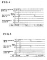
- Fig. 4 is a timing chart for explaining operation of the controller during an automatic operation mode
- Fig. 5 is another timing chart for explaining operation of the controller during a manual operation mode
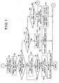
- Fig. 7 is a flowchart for explaining an operation of the controller following the flowchart in Fig. 6.
- a swing door 11 as a vehicle door is supported by use of a known hinge (not illustrated) and is operated to open and close a door opening defined in a vehicle side body.
- a vehicle door opening and closing apparatus 12 is mounted on the swing door 11, an apparatus 12 which controls opening operations, and closing operations, of the swing door 11.
- the vehicle door opening and closing apparatus 12 is provided with an outside automatic operation switch 21 (second operating means) being positioned on the exterior of the swing door 11, an inside automatic operation switch 22 (the second operating means) being positioned on the interior of the swing door 11, an inside manual opening operation switch 26 (first operating means), an inside manual closing operation switch 27 (the first operating means), a door opening and closing operation-driving unit 23, a latch driving unit 24, and a controller 25.
- the door opening and closing operation-driving unit 23 will be described in detail later.
- the latch-driving unit 24 holds the swing door 11 relative to a vehicle side body at a fully closed state, in which the door opening is fully closed, or at a half-closed state, in which the door opening is half closed.
- the controller 25 is electrically connected to all these components 21, 22, 23, 24, 26, and 27.
- the outside automatic operation switch 21 outputs an automatic operation signal irrespective of whether or not the outside automatic operation switch 21 is continuously operated, once the outside automatic operation switch 21 is put into operation.
- the outside automatic operation switch 21 is operated outside the vehicle at a time that an automatic opening/closing operation of the swing door 1 is implemented by the door opening and closing operation-driving unit 23.
- the inside automatic operation switch 22 outputs an automatic operation signal irrespective of whether or not the inside automatic operation switch 22 is subsequently continuously operated, once the inside automatic operation switch 22 is put into operation.
- the inside automatic operation switch 22 is operated inside the vehicle at a time that an automatic opening/closing operation of the swing door 11 is implemented by the door opening and closing operation-driving unit 23.
- the automatic opening/closing operation of the swing door 11 includes an operation from the fully closed state to the fully open state, and an operation from the fully open state to the fully closed state.
- the inside manual opening operation switch 26 continuously outputs a manual operation signal, confined to times when the inside manual opening operation switch 26 is continuously being operated.
- the inside manual opening operation switch 26 is operated inside the vehicle at a time that a manual opening operation of the swing door 11 is implemented by the door opening and closing operation driving unit 23.
- the inside manual closing operation switch 27 continuously outputs a manual operation signal, confined to times when the inside manual closing operation switch 27 is continuously being operated.
- the inside manual closing operation switch 27 is operated inside the vehicle at a time that a manual closing operation of the swing door 11 is implemented by the door opening and closing driving unit 23.
- the latch-driving unit 24 includes a latch engageable with a striker fixed at the vehicle side body, and a pole engageable with the latch during a door latched condition in which the striker is being engaged with the latch.
- the latch-driving unit 24 further includes a known structure which is capable of establishing a door latched condition, a door half-latched condition, and a door unlatched condition.
- the latch-driving unit 24 still further includes an actuator that is operated for the purpose of switching the above-described door latched/unlatched/half-latched condition.
- the controller 25 controls a driving of the actuator of the latch-driving unit 24, wherein the swing door 11 is switched from the door latched condition to the door unlatched condition when the swing door 11 is to be opened, on the other hand, the swing door 11 is switched from the door half latched condition to the door latched condition when the swing door 11 is to be closed.
- the door opening and closing driving unit 23 is attached to the swing door 11, and moves a lever 14 back and forth, of which one end is connected to the swing door 11, and the other end is connected to a pillar 13, wherein the swing door 11 is rotated with the hinge as a fulcrum, and the door opening is closed or opened.
- the controller 25 controls the latch-driving unit 24 and switches the swing door 11 from the door latched condition to the door unlatched condition.
- the controller 25 in succession controls the door opening and closing-driving unit 23 so as to rotate the swing door 11, wherein the door opening is opened.
- the controller 25 controls the door opening and closing-driving unit 23 and rotates the swing door 11.
- the controller 25 in succession controls the latch-driving unit 24, wherein the swing door 11 is switched to the door latched condition so as to close the door opening.
- the door opening and closing-driving unit 23 is configured with a door driving motor 31 as a driving power source, a first speed reduction mechanism 32, an electromagnetic clutch 33 as a power transmitting mechanism, a second speed reduction mechanism 34, and a lever-operating portion 35 as an operating mechanism.
- the door driving motor 31 operates in response to a drive signal from the controller 25, and rotates a rotational shaft 31a in a normal rotational direction or in a reverse rotational direction.
- the electromagnetic clutch 33 is provided with two frictional plates 33a and 33b; the frictional plate 33a as a force transmitting member and the frictional plate 33b as a force-receiving member.
- the electromagnetic clutch 33 operates in response to an operation signal from the controller 25, and switches its condition between a joined condition, in which the frictional plate 33a is frictionally engaged with the frictional plate 33b, and a cutoff condition, in which the frictional plate 33a is disengaged from the frictional plate 33b.
- rotation of the door driving motor 31 is transmitted to the lever-operating portion 35.
- a pulse sensor 36 as a detecting means is preferably positioned between the electromagnetic clutch 33 and the second speed reduction mechanism 34.
- the pulse sensor 36 outputs a signal corresponding to rotation transmitted between the electromagnetic clutch 33 and the second speed reduction mechanism 34, or a signal corresponding to a rotational condition transmitted to the electromagnetic clutch 33 from the first speed reduction mechanism 32.
- a Hall element is one of the examples for the pulse sensor 36, as a non-limiting example.
- the Hall element is mounted so as to output, to the controller 25, a predetermined pulse signal corresponding to variation in magnetic flux of a magnet attached at the frictional plate 33b.
- the controller 25 counts the number of pulse signals and computes a rotational number (rotational speed) of the frictional plate 33b.
- the controller 25 incorporates, therein, a CPU (central processing unit) 41, a motor driving circuit 42, a clutch driving circuit 43, and a pulse width modulation circuit 44.
- a CPU central processing unit
- the CPU 41 is electrically connected, via an input circuit 46, to the outside automatic operation switch 21, the inside automatic operation switch 22, an inside manual opening operation switch 26, and an inside manual closing operation switch 27.
- the CPU 41 is able to compute, on the basis of an automatic operation signal and a manual operation signal therefrom, the presence or absence of an opening operation, and a closing operation, of the swing door 11.
- the CPU 41 is further electrically connected to the pulse sensor 36 via an input circuit 47.
- the CPU 41 is able to count the number of pulse signals outputted from the pulse sensor 36 and to compute the rotational number (rotational speed) of the frictional plate 33b.
- the CPU 41 computes, on the basis of the pulse signals from the pulse sensor 36, a position of the swing door 11 being moved, and further computes an opening/closing speed of the swing door 11.
- the motor driving circuit 42 is electrically connected to the CPU 41 and is applied with a battery voltage from a battery B illustrated in Fig. 3. In response to a driving signal fed from the CPU 41 to the motor driving circuit 42, the motor driving circuit 42 supplies, by use of a polarity corresponding to the driving signal, an electric power to a door driving motor 31 of the door opening and closing-driving unit 23.
- the clutch driving circuit 43 is electrically connected to the CPU 41 and is applied with a battery voltage from the battery B illustrated in Fig. 3. In response to an operation signal fed from the CPU 41 to the clutch driving circuit 43, the clutch driving circuit 43 supplies an operation electric power, or ceases the supply, for the purpose of operating the electromagnetic clutch 33 of the door opening and closing-driving unit 23.
- the pulse width modulation circuit 44 is interposed between the CPU 41 and the door driving motor 31 in such a manner that the CPU 41 is electrically connected to the door driving motor 31 via the pulse width modulation circuit 44.
- the pulse width modulation circuit 44 is able to modulate a value of electric power to be supplied to the door driving motor 31.
- a pulse width modulation circuit 45 is interposed between the CPU 41 and the electromagnetic clutch 33 in such a manner that the CPU 41 is electrically connected to the electromagnetic clutch 33 via the pulse width modulation circuit 45.
- the pulse width modulation circuit 45 is able to modulate a value of electric power to be supplied to the electromagnetic clutch 33.
- the CPU 41 alters a pulse width of a control signal fed to the pulse width modulation circuit 44, in response to a driving condition of the door driving motor 31 to be controlled. Likewise, the CPU 41 alters a pulse width of a control signal fed to the pulse width modulation circuit 45, in response to a joined condition of the electromagnetic clutch 33 to be controlled.
- the pulse width modulation circuits 44 and 45 are respectively provided with switching elements 44a and 45a to be turned on and off in response to the control signals.
- an N-channel MOS transistor can be employed as the switching element as a non-limiting example.
- the pulse width modulation circuit 44 is capable of modulating, in accordance with a ratio of turning the switching element 44a on and off, a mean value of an electric current supplied to the door driving motor 31.
- the CPU 41 controls a driving output (output torque) of the door driving motor 31 by means of a so-called PWM control by the pulse width modulation circuit 44.
- the pulse width modulation circuit 45 is capable of modulating, in accordance with a ratio of turning the switching element 45a on and off, a mean value of an electric current supplied to the electromagnetic clutch 33. That is, the CPU 41 controls a clutch output of the electromagnetic clutch 33 (a frictional engagement condition between the frictional plates 33a and 33b) by means of a so-called PWM control by the pulse width modulation circuit 45.
- the CPU 41 outputs a driving signal to supply a driving electric power to the door driving motor 31, and outputs a control signal to the pulse width modulation circuit 44 to turn the switching element 44a on and off.
- the door driving motor 31 is supplied with a mean electric current in response to an intermittent on operation of the switching element 44a, wherein the door driving motor 31 is activated.
- the electromagnetic clutch 33 during a discontinuation state in which an operation electric power is not supplied to the electromagnetic clutch 33, the electromagnetic clutch 33 is at the cutoff condition in which the frictional plates 33a and 33b are disengaged from each other. These frictional plates 33a and 33b enters into an engaged condition in response to a value of a driving electric power to be supplied from the motor driving circuit 42. Therefore, the CPU 41 outputs an operation stop signal so as not to supply an operation electric power to the electromagnetic clutch 33, wherein the electromagnetic clutch 33 enters into the cutoff condition.
- the CPU 41 outputs an operation signal to supply an operation electric power to the electromagnetic clutch 33, and outputs a control signal to the pulse width modulation circuit 45 to turn the switching element 45a on and off.
- the electromagnetic clutch 33 is supplied with a mean electric current in response 10 an intermittent on operation of the switching element 45a, wherein the electromagnetic clutch 33 enters into the joined condition.
- controller 25 especially an operation relevant to the door opening and closing-driving unit 23 with reference to timing charts illustrated in Figs. 4 and 5.
- Described below is an automatic operation mode implemented by the vehicle opening and closing apparatus according to the embodiment of the present invention.
- an operation signal from the outside automatic operation switch 21 or the inside automatic operation switch 22 is inputted to the controller 25.
- the controller 25 In order to open the swing door 11 by use of a driving force of the door driving motor 31, the controller 25 outputs a driving signal to the motor driving circuit 42 and outputs an operation signal to the clutch driving circuit 43, thereby driving the door driving motor 31 as well as operating the electromagnetic clutch 33. Because a driving signal to the motor driving circuit 42 is employed to rotate the door driving motor 31 in a normal direction, the lever 14 is moved forth or pushed by the lever operating portion 35, wherein the swing door 11 is rotated in a direction to open the door opening.
- a driving signal sent to the motor driving circuit 42 includes a component to move back or pull the lever 14, the swing door 11 is rotated in a reverse direction to close the door opening.
- a driving signal sent to the motor driving circuit 42 is employed for the purpose of controlling the pulse width modulation circuit 44 to modulate or alter a value of electric power to be supplied to the door driving motor 31 in such a manner that a driving torque as a driving output is controlled at a predetermined value (a first torque value).
- an operation signal sent to the clutch driving circuit 43 is employed for the purpose of controlling the pulse width modulation circuit 45 to modulate or alter a value of electric power to be supplied to the electromagnetic clutch 33 in such a manner that a clutch output is controlled at a predetermined value (a first output value) which corresponds to an opening/closing position, and/or an opening/closing speed, of the swing door 11.
- a predetermined value of the clutch output is set in such a manner that a frictional engagement between the frictional plates 33a and 33b can be always assured at the essentially minimum extent for transmitting rotation of the door driving motor 31 to the lever operating portion 35.
- the controller 25 then detects, on the basis of a pulse signal from the pulse sensor 36, the swing door 11 positioned at the fully, opened position. In this case, the controller 25 outputs a discontinuation signal to the motor driving circuit 42 and stops driving the door driving motor 31. As a result, the opening operation of the swing door 11, which is implemented to open the door opening by the driving force of the door driving motor 31, is stopped, and a clutch output is controlled at a predetermined value (a second output value). The predetermined value of the clutch output at this point is controlled at an adequate value for holding the swing door 11 at a predetermined holding load.
- This predetermined holding load corresponds to a load of which level is adequate to cope with a natural force such as a wind blowing to the swing door 11, a force that rotates the swing door 11 in an opening or closing direction at an event that a vehicle has been parked on a slope, and so on.
- a driving force of the door driving motor 31 it is preferable that the door driving motor 31 is driven in a reverse rotational direction by operating the outside or inside automatic operation switch 21 or 22.
- the operation of the electromagnetic clutch 33 and so on is the same as described above.
- Described below is a manual operation mode implemented by the vehicle opening and closing apparatus according to the embodiment of the present invention.
- an operation signal from the inside manual opening operation switch 26 is inputted to the controller 25.
- the controller 25 In order to open the swing door 11 by use of a driving force of the door driving motor 31, the controller 25 outputs a driving signal to the motor driving circuit 42 and outputs an operation signal to the clutch driving circuit 43, thereby driving the door driving motor 31 as well as operating the electromagnetic clutch 33. Because a driving signal to the motor driving circuit 42 is employed to rotate the door driving motor 31 in a normal direction, the lever 14 is moved forth or pushed by the lever operating portion 35, wherein the swing door 11 is rotated in a direction to open the door opening.
- a driving signal sent to the motor driving circuit 42 includes a component to move back or pull the lever 14, the swing door 11 is rotated in a reverse direction to close the door opening.
- a driving signal sent to the motor driving circuit 42 is employed for the purpose of controlling the pulse width modulation circuit 44 to modulate or alter a value of electric power to be supplied to the door driving motor 31 in such a manner that a driving output, i.e., a driving torque, is controlled at a predetermined value (a third torque value or a fourth torque value) which is higher than the first torque value.
- an operation signal sent to the clutch driving circuit 43 is employed for the purpose of controlling the pulse width modulation circuit 45 to modulate or alter a value of electric power to be supplied to the electromagnetic clutch 33 in such a manner that a clutch output is controlled at the highest value.
- the fourth torque value is a driving force that the door driving motor 31 is capable of outputting at the maximum level.
- the third torque value is lower than the fourth torque value, and but is higher than the first torque value.
- the opening operation of the swing door 11, which is implemented to open the door opening by the driving force of the door driving motor 31, is stopped, and a clutch output is controlled at the predetermined value (the second output value,).
- the predetermined value of the clutch output at this point is controlled at an adequate value for holding the swing door 11 at a predetermined holding load.
- the CPU 41 determines on the basis of an automatic operation signal whether either the outside automatic operation switch 21 or the inside automatic operation switch 22 was put into operation.
- the CPU 41 determines on the basis of a manual operation signal whether either the inside manual opening operation switch 26 or the inside manual closing operation switch 27 is being operated.
- the automatic operation mode is selected so as to implement steps S3 to S17.
- the driving force to drive the door driving motor 31 is controlled to the first torque value.
- the electromagnetic clutch 33 is operated so as to generate the clutch output at the first output value.
- an opening operation, or a closing operation, of the swing door 11 is commenced.
- the CPU 41 obtains a pulse signal from the pulse sensor 36.
- the CPU 41 computes a door opening/closing speed N1 of the swing door 11 and a current door opening/closing position P1 of the swing door 11.
- This information is stored in a RAM (random access memory) incorporated in the CPU 41.
- the CUP 41 determines whether a difference between an opening/closing speed of the swing door 11 (corresponding to a previous door opening/closing speed N0), which has been stored in the RAM of the CPU 41, and the opening/closing speed of the swing door 11 (corresponding to the opening/closing speed N1), which was stored at step S6 immediately before proceeding to step S7, exceeds a predetermined deceleration rate.
- the CPU 41 determines at step S7 that the difference therebetween exceeds the predetermined deceleration rate, the CPU 41 determines that the swing door 11 is being applied with an overload.
- step S8 the CPU 41 sends a driving signal to the motor circuit 42 for the purpose of rotating the door driving motor 31 in a reverse rotational direction, wherein the swing door 11 is rotated to a predetermined door position.
- step S9 the CPU 41 determines if the swing door 11 has moved to the predetermined door position.
- the program proceeds to step S10, wherein a driving of the door driving motor 31 is discontinued, i.e., stopped.
- step S11 the CPU 41 controls operation of the electromagnetic clutch 33 in such a manner that the clutch output is controlled at the second output value, wherein the swing door 11 is supportively maintained.
- step S7 when the CPU 41 determines that the difference therebetween does not exceed the predetermined deceleration rate, the CPU 41 determines that the swing door 11 is not being applied with an overload. In such circumstances, at steps S12 and S13, the opening/closing operation of the swing door 11 is continued until the CPU 41 determines on the basis of the door opening/closing position P1 computed at step S6 that the swing door 11 is positioned at the fully open state or at the fully closed state.
- step S12 when the CPU 41 determines that the swing door 11 is at the fully open state, the program proceeds to step S14, wherein a driving of the door driving motor 31 is discontinued, i.e., stopped.
- step S15 the CPU 41 controls operation of the electromagnetic clutch 33 in such a manner that the clutch output is controlled at the second output value wherein the swing door 11 is held.
- step S13 when the CPU 41 determines that the swing door 11 is at the fully closed state, the program proceeds to step S16, wherein a driving of the door driving motor 31 is discontinued, i.e., stopped.
- step S17 the CPU 41 discontinues, i.e., stops, the operation of the electromagnetic clutch 31.
- the manual operation mode is selected so as to implement steps S18 to S25.
- the CPU 41 determines whether or not an overload was detected during the last automatic operation mode.
- the program proceeds to step S19, wherein the CPU 41 controls the driving motor to generate a driving force at the maximum level (a second torque value or the fourth torque value).
- the CPU 41 controls operation of the electromagnetic clutch 33 to generate a clutch output at the maximum level, wherein an opening operation, or a closing operation, of the swing door 11 is commenced.
- step S18 the program proceeds to step S21, wherein the CPU 41 drives the door driving motor 31 to generate a driving force at the third torque value.
- step S22 the CPU 41 controls the operation of the electromagnetic clutch 33 to generate a clutch output at the maximum level, wherein an opening operation, or a closing operation, of the swing door 11 is commenced. If an operation, of the inside manual opening operation switch 26, or of the inside manual closing operation switch 27 is discontinued, i.e., stopped, during the opening/closing operation of the swing door 11, at step S23, the CPU 41 determines whether or not a manual operation signal is being inputted.
- step S23 When a negative answer No is obtained at step S23, the program proceeds to step S24, wherein a driving of the door driving motor 31 is discontinued, i.e., stopped.
- step S25 the CPU 41 controls the electromagnetic clutch 33 to generate a clutch output at the second output value, wherein the swing door 11 is held.
- an affirmative answer Yes is obtained at step S23, i.e., unless an operation, of the inside manual opening operation switch 26, or of the inside manual closing operation switch 27, is discontinued, i.e., stopped, the program returns to step S18, and the above described routine is repeated.
- the third torque value, or the fourth torque value, of the door driving motor 31 for the duration of the manual operation mode is higher than the first torque value of the door driving motor 31 for the duration of the automatic operation mode, even if, for the duration of the automatic operation mode, an overload is imposed on the swing door 11 and a driving of the door driving motor 31 is stopped, an opening/closing operation of the swing door 11, which is implemented by a driving force of the door driving motor 31, is able to be assured while the manual operation mode is being selected. Therefore, comparing with a conventional work, it is possible to enhance convenience for opening and closing the swing door 11.
- the embodiment of the present invention because it is possible to detect the presence or absence of an overload being applied to the swing door 11 for the duration of the automatic operation mode, it is possible to assure safety for opening and closing the swing door 11.
- the duration of the manual operation mode as far as an operation, of the manual opening operation switch 26, or of the manual closing operation switch 27 is discontinued or stopped, an opening/closing operation of the swing door 11 is discontinued, thereby enabling to assure safety.
- the door driving motor 31 when the presence of an overload was detected during the automatic operation mode, the door driving motor 31 is controlled to generate a driving force at the fourth torque value.
- the door driving motor 31 when the absence of an overload was detected during the automatic operation mode, the door driving motor 31 is controlled to generate a driving force at the third torque value.
- a driving force from the door driving motor 31 is not necessarily controlled between the third and fourth torque value as described above.
- the driving output (the second torque value) of the door driving motor 31 is designed to be equivalent to the fourth torque value, which is the maximum driving output value of the door driving motor 31.
- the first torque value during the automatic operation mode corresponds to a first driving output value
- the second torque value during the manual operation mode corresponds to a second driving output value
- the second driving output value is designed to be equal to, or greater than, the first driving output value.
- the third driving output value is designed to be equal to, or greater than the first driving output value.
- the fourth driving output value is designed to be greater than the third driving output value. In this case, it is preferable that the fourth driving output value is the maximum driving output value that the door driving motor 31 (the driving power source) is capable of outputting.
- the vehicle door opening and closing apparatus 12 acts to rotate the swing door 11 by use of a driving force of the door driving motor 31.
- this apparatus can act to slidably move a slide door by use of a driving force of the door driving motor 31.
- an opening/closing operation of the vehicle door includes a rotation of the swing door 11, a slide movement of the slide door, and so on.
- the second driving output value, which the driving power source outputs during the manual operation mode is higher than the first driving output value during the automatic operation mode, even if a driving of the driving power source is discontinued, i.e., stopped, during the automatic operation mode due to detection of an overload being applied to the vehicle door, it is possible to implement, during the manual operation mode, an opening/closing operation of the vehicle door which is performed by driving the driving power source. Therefore, comparing with a conventional work, it is possible to enhance convenience for opening and closing the vehicle door. Further, according to the embodiment of the present invention, because it is possible to detect the presence or absence of an overload being applied to the swing door 11 for the duration of the automatic operation mode, it is possible to assure safety for opening and closing the swing door 11.
- a controller (25) controls, based upon a manual operation signal from a first operating means (26 or 27) and the automatic operation signal from a second operating means (21 or 22), a driving of a driving power source (31) for generating a driving force for an opening/closing operation of a vehicle door (11).
- the controller switches control for driving the driving power source.
- An automatic operation mode is selected when the automatic operation signal is inputted to the controller, in which the driving power source is driven to output a predetermined first driving output value.
- a manual operation mode is selected when the manual operation signal is inputted to the controller in which the driving power source is driven to output a second driving output value which is higher than the first driving output value.
Landscapes
- Power-Operated Mechanisms For Wings (AREA)
Abstract
A controller (25) controls, based upon a manual operation signal from a first operating means (26 or 27) and the automatic operation signal from a second operating means (21 or 22), a driving of a driving power source (31) for generating a driving force for an opening/closing operation of a vehicle door (11). The controller switches control for driving the driving power source. An automatic operation mode is selected when the automatic operation signal is inputted to the controller, in which the driving power source is driven to output a predetermined first driving output value. A manual operation mode is selected when the manual operation signal is inputted to the controller in which the driving power source is driven to output a second driving output value which is higher than the first driving output value.
Description
- This invention generally relates to a vehicle door opening and closing apparatus which operates a vehicle door to open and close an opening defined in a vehicle body such as a vehicle side door and a back door (tail gate)
- Conventionally, as is disclosed in JP1994(06)-144000A, this type of vehicle door opening and closing apparatus is provided with a driving power source configured to generate a driving force relevant to an opening/closing movement of a vehicle door, an opening/closing mechanism for operating a vehicle door by a driving force of the driving power source in such a manner that an opening defined in a vehicle body is opened and closed, an operating means for outputting an operation signal in response to its operation, and a controlling means for controlling, on the basis of the operation signal, a driving of the driving power source. This apparatus is further provided with an overload-detecting means for detecting a load applied to the vehicle door. When the controlling means determines on the basis of a signal from the overload-detecting means that the vehicle door has been subjected to an overload, the controlling means implements a control by which a driving of the driving power source is ceased. This apparatus is still further provided with a vehicle door operation intention-detecting means for detecting an intention of a user to manually operate the vehicle door. When the controlling means has determined on the basis of a signal from the overload-detecting means that the vehicle door has been subjected to an overload, if the controlling means determines on the basis of a signal from the vehicle door operation intension-detecting means that a user intends to manually operate the vehicle door, the controlling means switches an actually running mode to a manual operation mode.
- According to the above described vehicle door opening and closing apparatus, however, when a load being applied to the vehicle door is, for example, too great to manually open or close the vehicle door, the controlling means ceases driving the driving power source in response to a signal from the overload-detecting means. Therefore, it is not possible to open and close the vehicle door by use of a driving force of the driving power source, and is further not possible to open and close the vehicle door even manually. In such a case, there is a danger of the convenience, which is required upon opening and closing the vehicle door, of being deteriorated. Further, when a signal from the overload-detecting means is employed to control an obstacle entrapment detection while the vehicle door is being opened and closed, normally, the driving power source is controlled to generate an output value at a low level so that load applied to an entrapped obstacle can be restrained. Accordingly, it is obvious that convenience above described would be damaged.
- The present invention has been made in view of the above circumstances, and provides a vehicle door opening and closing apparatus which is capable of assuring safety of an opening/closing operation of a vehicle door, and of enhancing convenience thereof.
- According to an aspect of the present invention, a vehicle door opening and closing apparatus including a driving power source configured to generate a driving force relevant to an opening operation, and a closing operation, of a vehicle door and an opening-closing mechanism capable of implementing the opening operation, and the closing operation, of the vehicle door by the driving force of the driving power source. This vehicle door opening and closing apparatus is characterized in further including: a first operating means for continuously outputting a manual operation signal, confined to times when the first operating means is continuously being operated; a second operating means for outputting an automatic operation signal irrespective of whether or not the second operating means is continuously operated, once the second operating means is put into operation; and a controlling means for controlling, on the basis of the manual operation signal and the automatic operation signal, a driving of the driving power source. The controlling means is capable of switching control for driving the driving power source in such a manner that an automatic operation mode is selected at a time that the automatic operation signal is inputted to the controlling means, the automatic operation mode in which the driving power source is driven to output a predetermined first driving output value, and a manual operation mode is selected at a time that the manual operation signal is inputted to the controlling means, the manual operation mode in which the driving power source is driven to output a second driving output value which is higher than the first driving output value.
- It is preferable that the vehicle door opening and closing apparatus further includes a detecting means for outputting a signal representing an operating state of the vehicle door. The controlling means computes, on the basis of the signal from the detecting means, an opening speed, and a closing speed, of the vehicle door, the controlling means implements a discontinuation control during the automatic operation mode, the discontinuation control by which the driving of the driving power source is discontinued at an event that the opening speed, or the closing speed, of the vehicle door is decelerated beyond a predetermined speed value, and the controlling means prohibits the discontinuation control for the duration of the manual operation mode.
- It is further preferable that the controlling means implements a normal driving control by which driving of the driving power source is controlled in such a manner that the driving power source outputs a third driving output value during the manual operation mode prior to implementing the discontinuation control, and implements an urgent driving control by which driving of the driving power source is controlled in such a manner that the driving power source outputs a fourth driving output value, which is higher than the third driving output value, during the manual operation mode after implementing the discontinuation control.
- It is still further preferable that the first driving output value is quantitatively equivalent to the third driving output value, and the second driving output value is quantitatively equivalent to the fourth driving output value.
- It is still further preferable that the first driving output value is lower than the third driving output value.
- The foregoing and additional features and characteristics of the present invention will become more apparent from the following detailed description considered with reference to the accompanying drawings, wherein:
- Fig. 1 is a block view of a vehicle door on which a vehicle door opening and closing apparatus according to an embodiment of the present invention is mounted;
- Fig. 2 is a block view schematically illustrating the vehicle door opening and closing apparatus;
- Fig. 3 is a circuit view illustrating a controller for controlling the vehicle door opening and closing apparatus;
- Fig. 4 is a timing chart for explaining operation of the controller during an automatic operation mode;
- Fig. 5 is another timing chart for explaining operation of the controller during a manual operation mode;
- Fig. 6 is a flowchart for explaining an operation of the controller according to the embodiment of the present invention; and
- Fig. 7 is a flowchart for explaining an operation of the controller following the flowchart in Fig. 6.
- An embodiment of the present invention will be described hereinbelow in detail with reference to the accompanying drawings.
- As is illustrated in Fig. 1, a
swing door 11 as a vehicle door is supported by use of a known hinge (not illustrated) and is operated to open and close a door opening defined in a vehicle side body. A vehicle door opening and closingapparatus 12 is mounted on theswing door 11, anapparatus 12 which controls opening operations, and closing operations, of theswing door 11. - The vehicle door opening and
closing apparatus 12 is provided with an outside automatic operation switch 21 (second operating means) being positioned on the exterior of theswing door 11, an inside automatic operation switch 22 (the second operating means) being positioned on the interior of theswing door 11, an inside manual opening operation switch 26 (first operating means), an inside manual closing operation switch 27 (the first operating means), a door opening and closing operation-driving unit 23, alatch driving unit 24, and acontroller 25. The door opening and closing operation-drivingunit 23 will be described in detail later. The latch-drivingunit 24 holds theswing door 11 relative to a vehicle side body at a fully closed state, in which the door opening is fully closed, or at a half-closed state, in which the door opening is half closed. Thecontroller 25 is electrically connected to all thesecomponents - The outside
automatic operation switch 21 outputs an automatic operation signal irrespective of whether or not the outsideautomatic operation switch 21 is continuously operated, once the outsideautomatic operation switch 21 is put into operation. The outsideautomatic operation switch 21 is operated outside the vehicle at a time that an automatic opening/closing operation of theswing door 1 is implemented by the door opening and closing operation-drivingunit 23. Likewise, the inside automatic operation switch 22 outputs an automatic operation signal irrespective of whether or not the insideautomatic operation switch 22 is subsequently continuously operated, once the insideautomatic operation switch 22 is put into operation. The insideautomatic operation switch 22 is operated inside the vehicle at a time that an automatic opening/closing operation of theswing door 11 is implemented by the door opening and closing operation-drivingunit 23. Hereinafter, the automatic opening/closing operation of theswing door 11 includes an operation from the fully closed state to the fully open state, and an operation from the fully open state to the fully closed state. The inside manualopening operation switch 26 continuously outputs a manual operation signal, confined to times when the inside manualopening operation switch 26 is continuously being operated. The inside manualopening operation switch 26 is operated inside the vehicle at a time that a manual opening operation of theswing door 11 is implemented by the door opening and closingoperation driving unit 23. Likewise, the inside manualclosing operation switch 27 continuously outputs a manual operation signal, confined to times when the inside manualclosing operation switch 27 is continuously being operated. The inside manualclosing operation switch 27 is operated inside the vehicle at a time that a manual closing operation of theswing door 11 is implemented by the door opening and closingdriving unit 23. - The latch-driving
unit 24 includes a latch engageable with a striker fixed at the vehicle side body, and a pole engageable with the latch during a door latched condition in which the striker is being engaged with the latch. The latch-drivingunit 24 further includes a known structure which is capable of establishing a door latched condition, a door half-latched condition, and a door unlatched condition. The latch-drivingunit 24 still further includes an actuator that is operated for the purpose of switching the above-described door latched/unlatched/half-latched condition. Thecontroller 25 controls a driving of the actuator of the latch-drivingunit 24, wherein theswing door 11 is switched from the door latched condition to the door unlatched condition when theswing door 11 is to be opened, on the other hand, theswing door 11 is switched from the door half latched condition to the door latched condition when theswing door 11 is to be closed. - The door opening and closing
driving unit 23 is attached to theswing door 11, and moves alever 14 back and forth, of which one end is connected to theswing door 11, and the other end is connected to apillar 13, wherein theswing door 11 is rotated with the hinge as a fulcrum, and the door opening is closed or opened. - When the
swing door 11 has been closed, in response to an operation, of the outsideautomatic operation switch 21, or of the insideautomatic operation switch 22, thecontroller 25 as a controlling means controls the latch-drivingunit 24 and switches theswing door 11 from the door latched condition to the door unlatched condition. Thecontroller 25 in succession controls the door opening and closing-drivingunit 23 so as to rotate theswing door 11, wherein the door opening is opened. When theswing door 11 has been open, in response to an operation, of the outsideautomatic operation switch 21, or of the insideautomatic operation switch 22, thecontroller 25 controls the door opening and closing-drivingunit 23 and rotates theswing door 11. Thecontroller 25 in succession controls the latch-drivingunit 24, wherein theswing door 11 is switched to the door latched condition so as to close the door opening. - Next, described below is an operation of the door opening and closing-driving
unit 23. - As is illustrated in Fig. 2, the door opening and closing-driving
unit 23 is configured with adoor driving motor 31 as a driving power source, a firstspeed reduction mechanism 32, anelectromagnetic clutch 33 as a power transmitting mechanism, a secondspeed reduction mechanism 34, and a lever-operating portion 35 as an operating mechanism. - The
door driving motor 31 operates in response to a drive signal from thecontroller 25, and rotates arotational shaft 31a in a normal rotational direction or in a reverse rotational direction. Theelectromagnetic clutch 33 is provided with twofrictional plates frictional plate 33a as a force transmitting member and thefrictional plate 33b as a force-receiving member. Theelectromagnetic clutch 33 operates in response to an operation signal from thecontroller 25, and switches its condition between a joined condition, in which thefrictional plate 33a is frictionally engaged with thefrictional plate 33b, and a cutoff condition, in which thefrictional plate 33a is disengaged from thefrictional plate 33b. During the joined condition of theelectromagnetic clutch 33, rotation of thedoor driving motor 31 is transmitted to the lever-operatingportion 35. Thelever operating portion 35, which is connected to thelever 14, converts rotation of thedoor driving motor 31, which is transmitted thereto via theelectromagnetic clutch 33, to a linear motion, wherein thelever 14 is moved back and forth. The firstspeed reduction mechanism 32 is employed to interconnect therotational shaft 31a of thedoor driving motor 31 and thefrictional plate 33a of theelectromagnetic clutch 33. The firstspeed reduction mechanism 32 is capable of decelerating rotation of therotational shaft 31a at a predetermined speed reduction ratio, and is capable of transmitting the decelerated rotation of therotational shaft 31a to thefrictional plate 33a. The secondspeed reduction mechanism 34 is employed to interconnect thefrictional plate 33b of theelectromagnetic clutch 33 and the lever-operatingportion 35. The secondspeed reduction mechanism 34 is capable of decelerating rotation of thefrictional plate 33b at a predetermined speed reduction ratio, and is capable of transmitting the decelerated rotation of thefrictional plate 33b to the lever-operatingportion 35. - As is illustrated in Figs. 2 and 3, a
pulse sensor 36 as a detecting means is preferably positioned between theelectromagnetic clutch 33 and the secondspeed reduction mechanism 34. Thepulse sensor 36 outputs a signal corresponding to rotation transmitted between theelectromagnetic clutch 33 and the secondspeed reduction mechanism 34, or a signal corresponding to a rotational condition transmitted to the electromagnetic clutch 33 from the firstspeed reduction mechanism 32. A Hall element is one of the examples for thepulse sensor 36, as a non-limiting example. The Hall element is mounted so as to output, to thecontroller 25, a predetermined pulse signal corresponding to variation in magnetic flux of a magnet attached at thefrictional plate 33b. Thecontroller 25 counts the number of pulse signals and computes a rotational number (rotational speed) of thefrictional plate 33b. - Next, described below is a structure of the
controller 25. - As is illustrated in Fig. 3, the
controller 25 incorporates, therein, a CPU (central processing unit) 41, a motor driving circuit 42, aclutch driving circuit 43, and a pulsewidth modulation circuit 44. - The
CPU 41 is electrically connected, via aninput circuit 46, to the outsideautomatic operation switch 21, the insideautomatic operation switch 22, an inside manualopening operation switch 26, and an inside manualclosing operation switch 27. TheCPU 41 is able to compute, on the basis of an automatic operation signal and a manual operation signal therefrom, the presence or absence of an opening operation, and a closing operation, of theswing door 11. TheCPU 41 is further electrically connected to thepulse sensor 36 via aninput circuit 47. TheCPU 41 is able to count the number of pulse signals outputted from thepulse sensor 36 and to compute the rotational number (rotational speed) of thefrictional plate 33b. TheCPU 41 computes, on the basis of the pulse signals from thepulse sensor 36, a position of theswing door 11 being moved, and further computes an opening/closing speed of theswing door 11. - The motor driving circuit 42 is electrically connected to the
CPU 41 and is applied with a battery voltage from a battery B illustrated in Fig. 3. In response to a driving signal fed from theCPU 41 to the motor driving circuit 42, the motor driving circuit 42 supplies, by use of a polarity corresponding to the driving signal, an electric power to adoor driving motor 31 of the door opening and closing-drivingunit 23. - The
clutch driving circuit 43 is electrically connected to theCPU 41 and is applied with a battery voltage from the battery B illustrated in Fig. 3. In response to an operation signal fed from theCPU 41 to theclutch driving circuit 43, theclutch driving circuit 43 supplies an operation electric power, or ceases the supply, for the purpose of operating theelectromagnetic clutch 33 of the door opening and closing-drivingunit 23. - The pulse
width modulation circuit 44 is interposed between theCPU 41 and thedoor driving motor 31 in such a manner that theCPU 41 is electrically connected to thedoor driving motor 31 via the pulsewidth modulation circuit 44. The pulsewidth modulation circuit 44 is able to modulate a value of electric power to be supplied to thedoor driving motor 31. Likewise, a pulsewidth modulation circuit 45 is interposed between theCPU 41 and the electromagnetic clutch 33 in such a manner that theCPU 41 is electrically connected to theelectromagnetic clutch 33 via the pulsewidth modulation circuit 45. The pulsewidth modulation circuit 45 is able to modulate a value of electric power to be supplied to theelectromagnetic clutch 33. TheCPU 41 alters a pulse width of a control signal fed to the pulsewidth modulation circuit 44, in response to a driving condition of thedoor driving motor 31 to be controlled. Likewise, theCPU 41 alters a pulse width of a control signal fed to the pulsewidth modulation circuit 45, in response to a joined condition of the electromagnetic clutch 33 to be controlled. The pulsewidth modulation circuits elements width modulation circuit 44 is capable of modulating, in accordance with a ratio of turning theswitching element 44a on and off, a mean value of an electric current supplied to thedoor driving motor 31. That is, theCPU 41 controls a driving output (output torque) of thedoor driving motor 31 by means of a so-called PWM control by the pulsewidth modulation circuit 44. Likewise, the pulsewidth modulation circuit 45 is capable of modulating, in accordance with a ratio of turning theswitching element 45a on and off, a mean value of an electric current supplied to theelectromagnetic clutch 33. That is, theCPU 41 controls a clutch output of the electromagnetic clutch 33 (a frictional engagement condition between thefrictional plates width modulation circuit 45. TheCPU 41 outputs a driving signal to supply a driving electric power to thedoor driving motor 31, and outputs a control signal to the pulsewidth modulation circuit 44 to turn theswitching element 44a on and off. As a result, thedoor driving motor 31 is supplied with a mean electric current in response to an intermittent on operation of theswitching element 44a, wherein thedoor driving motor 31 is activated. Regarding the electromagnetic clutch 33, during a discontinuation state in which an operation electric power is not supplied to the electromagnetic clutch 33, theelectromagnetic clutch 33 is at the cutoff condition in which thefrictional plates frictional plates CPU 41 outputs an operation stop signal so as not to supply an operation electric power to the electromagnetic clutch 33, wherein theelectromagnetic clutch 33 enters into the cutoff condition. TheCPU 41 outputs an operation signal to supply an operation electric power to the electromagnetic clutch 33, and outputs a control signal to the pulsewidth modulation circuit 45 to turn theswitching element 45a on and off. As a result, theelectromagnetic clutch 33 is supplied with a mean electric current in response 10 an intermittent on operation of theswitching element 45a, wherein theelectromagnetic clutch 33 enters into the joined condition. - Next, described below is an operation of the
controller 25, especially an operation relevant to the door opening and closing-drivingunit 23 with reference to timing charts illustrated in Figs. 4 and 5. - Described below is an automatic operation mode implemented by the vehicle opening and closing apparatus according to the embodiment of the present invention.
- When the outside
automatic operation switch 21 or the insideautomatic operation switch 22 is operated during the fully closed state of theswing door 11, an operation signal from the outsideautomatic operation switch 21 or the insideautomatic operation switch 22 is inputted to thecontroller 25. In order to open theswing door 11 by use of a driving force of thedoor driving motor 31, thecontroller 25 outputs a driving signal to the motor driving circuit 42 and outputs an operation signal to theclutch driving circuit 43, thereby driving thedoor driving motor 31 as well as operating theelectromagnetic clutch 33. Because a driving signal to the motor driving circuit 42 is employed to rotate thedoor driving motor 31 in a normal direction, thelever 14 is moved forth or pushed by thelever operating portion 35, wherein theswing door 11 is rotated in a direction to open the door opening. When a driving signal sent to the motor driving circuit 42 includes a component to move back or pull thelever 14, theswing door 11 is rotated in a reverse direction to close the door opening. In such circumstances, a driving signal sent to the motor driving circuit 42 is employed for the purpose of controlling the pulsewidth modulation circuit 44 to modulate or alter a value of electric power to be supplied to thedoor driving motor 31 in such a manner that a driving torque as a driving output is controlled at a predetermined value (a first torque value). On the other hand, an operation signal sent to theclutch driving circuit 43 is employed for the purpose of controlling the pulsewidth modulation circuit 45 to modulate or alter a value of electric power to be supplied to the electromagnetic clutch 33 in such a manner that a clutch output is controlled at a predetermined value (a first output value) which corresponds to an opening/closing position, and/or an opening/closing speed, of theswing door 11. Here, the predetermined value of the clutch output is set in such a manner that a frictional engagement between thefrictional plates door driving motor 31 to thelever operating portion 35. Thecontroller 25 then detects, on the basis of a pulse signal from thepulse sensor 36, theswing door 11 positioned at the fully, opened position. In this case, thecontroller 25 outputs a discontinuation signal to the motor driving circuit 42 and stops driving thedoor driving motor 31. As a result, the opening operation of theswing door 11, which is implemented to open the door opening by the driving force of thedoor driving motor 31, is stopped, and a clutch output is controlled at a predetermined value (a second output value). The predetermined value of the clutch output at this point is controlled at an adequate value for holding theswing door 11 at a predetermined holding load. This predetermined holding load corresponds to a load of which level is adequate to cope with a natural force such as a wind blowing to theswing door 11, a force that rotates theswing door 11 in an opening or closing direction at an event that a vehicle has been parked on a slope, and so on. When theswing door 11 is to be closed by use of a driving force of thedoor driving motor 31 while theswing door 11 is being positioned at the fully open condition, it is preferable that thedoor driving motor 31 is driven in a reverse rotational direction by operating the outside or insideautomatic operation switch electromagnetic clutch 33 and so on is the same as described above. - Described below is a manual operation mode implemented by the vehicle opening and closing apparatus according to the embodiment of the present invention.
- When the inside manual
opening operation switch 26 is operated, an operation signal from the inside manualopening operation switch 26 is inputted to thecontroller 25. In order to open theswing door 11 by use of a driving force of thedoor driving motor 31, thecontroller 25 outputs a driving signal to the motor driving circuit 42 and outputs an operation signal to theclutch driving circuit 43, thereby driving thedoor driving motor 31 as well as operating theelectromagnetic clutch 33. Because a driving signal to the motor driving circuit 42 is employed to rotate thedoor driving motor 31 in a normal direction, thelever 14 is moved forth or pushed by thelever operating portion 35, wherein theswing door 11 is rotated in a direction to open the door opening. When a driving signal sent to the motor driving circuit 42 includes a component to move back or pull thelever 14, theswing door 11 is rotated in a reverse direction to close the door opening. In such circumstances, a driving signal sent to the motor driving circuit 42 is employed for the purpose of controlling the pulsewidth modulation circuit 44 to modulate or alter a value of electric power to be supplied to thedoor driving motor 31 in such a manner that a driving output, i.e., a driving torque, is controlled at a predetermined value (a third torque value or a fourth torque value) which is higher than the first torque value. On the other hand, an operation signal sent to theclutch driving circuit 43 is employed for the purpose of controlling the pulsewidth modulation circuit 45 to modulate or alter a value of electric power to be supplied to the electromagnetic clutch 33 in such a manner that a clutch output is controlled at the highest value. The fourth torque value is a driving force that thedoor driving motor 31 is capable of outputting at the maximum level. The third torque value is lower than the fourth torque value, and but is higher than the first torque value. When thecontroller 25 is no longer inputted with the operation signal from the inside manualopening operation switch 26, thecontroller 25 outputs a discontinuation signal to the motor driving circuit 42 and stops driving thedoor driving motor 31. As a result, the opening operation of theswing door 11, which is implemented to open the door opening by the driving force of thedoor driving motor 31, is stopped, and a clutch output is controlled at the predetermined value (the second output value,). Likewise as an operation for stopping the opening operation of theswing door 11 during the automatic operation mode, the predetermined value of the clutch output at this point is controlled at an adequate value for holding theswing door 11 at a predetermined holding load. When theswing door 11 is to be closed by use of a driving force of thedoor driving motor 31, it is preferable that thedoor driving motor 31 is driven in a reverse rotational direction by operating the inside manualclosing operation switch 27. The operation of theelectromagnetic clutch 33 and so on is the same as described above. - Next, described below is control of the electromagnetic clutch 33 by the
controller 25 with reference to flowcharts illustrated in Figs. 6 and 7. - At step S1 in Fig. 6, the
CPU 41 determines on the basis of an automatic operation signal whether either the outsideautomatic operation switch 21 or the insideautomatic operation switch 22 was put into operation. At step S2 in Fig. 6, theCPU 41 determines on the basis of a manual operation signal whether either the inside manualopening operation switch 26 or the inside manualclosing operation switch 27 is being operated. - When the
CPU 41 determines at step S1 that either the outsideautomatic operation switch 21 or the insideautomatic operation switch 22 was operated, the automatic operation mode is selected so as to implement steps S3 to S17. In specific, at step S3, the driving force to drive thedoor driving motor 31 is controlled to the first torque value. At step S4, theelectromagnetic clutch 33 is operated so as to generate the clutch output at the first output value. As a result, an opening operation, or a closing operation, of theswing door 11 is commenced. In succession, at step S5, theCPU 41 obtains a pulse signal from thepulse sensor 36. At step S6, theCPU 41 computes a door opening/closing speed N1 of theswing door 11 and a current door opening/closing position P1 of theswing door 11. This information is stored in a RAM (random access memory) incorporated in theCPU 41. During the opening/closing operation of theswing door 11, at step S7, theCUP 41 determines whether a difference between an opening/closing speed of the swing door 11 (corresponding to a previous door opening/closing speed N0), which has been stored in the RAM of theCPU 41, and the opening/closing speed of the swing door 11 (corresponding to the opening/closing speed N1), which was stored at step S6 immediately before proceeding to step S7, exceeds a predetermined deceleration rate. When theCPU 41 determines at step S7 that the difference therebetween exceeds the predetermined deceleration rate, theCPU 41 determines that theswing door 11 is being applied with an overload. In such circumstances, at step S8, theCPU 41 sends a driving signal to the motor circuit 42 for the purpose of rotating thedoor driving motor 31 in a reverse rotational direction, wherein theswing door 11 is rotated to a predetermined door position. At step S9, theCPU 41 determines if theswing door 11 has moved to the predetermined door position. When theCPU 41 determines at step S9 that theswing door 11 has already been positioned at the predetermined door position, the program proceeds to step S10, wherein a driving of thedoor driving motor 31 is discontinued, i.e., stopped. At step S11 theCPU 41 controls operation of the electromagnetic clutch 33 in such a manner that the clutch output is controlled at the second output value, wherein theswing door 11 is supportively maintained. - At step S7, when the
CPU 41 determines that the difference therebetween does not exceed the predetermined deceleration rate, theCPU 41 determines that theswing door 11 is not being applied with an overload. In such circumstances, at steps S12 and S13, the opening/closing operation of theswing door 11 is continued until theCPU 41 determines on the basis of the door opening/closing position P1 computed at step S6 that theswing door 11 is positioned at the fully open state or at the fully closed state. At step S12, when theCPU 41 determines that theswing door 11 is at the fully open state, the program proceeds to step S14, wherein a driving of thedoor driving motor 31 is discontinued, i.e., stopped. At step S15, theCPU 41 controls operation of the electromagnetic clutch 33 in such a manner that the clutch output is controlled at the second output value wherein theswing door 11 is held. At step S13, when theCPU 41 determines that theswing door 11 is at the fully closed state, the program proceeds to step S16, wherein a driving of thedoor driving motor 31 is discontinued, i.e., stopped. At step S17, theCPU 41 discontinues, i.e., stops, the operation of theelectromagnetic clutch 31. - When the
CPU 41 determines at step S2 that either the inside manualopening operation switch 26 or the inside manualclosing operation switch 27 is being operated, the manual operation mode is selected so as to implement steps S18 to S25. In specific, at step S18, theCPU 41 determines whether or not an overload was detected during the last automatic operation mode. At step S18, when theCPU 41 determines that an overload was detected during the last automatic operation mode, the program proceeds to step S19, wherein theCPU 41 controls the driving motor to generate a driving force at the maximum level (a second torque value or the fourth torque value). At step S20, theCPU 41 controls operation of the electromagnetic clutch 33 to generate a clutch output at the maximum level, wherein an opening operation, or a closing operation, of theswing door 11 is commenced. - When the
CPU 41 determines at step S18 that an overload was not detected during the last automatic operation mode, the program proceeds to step S21, wherein theCPU 41 drives thedoor driving motor 31 to generate a driving force at the third torque value. At step S22, theCPU 41 controls the operation of the electromagnetic clutch 33 to generate a clutch output at the maximum level, wherein an opening operation, or a closing operation, of theswing door 11 is commenced. If an operation, of the inside manualopening operation switch 26, or of the inside manualclosing operation switch 27 is discontinued, i.e., stopped, during the opening/closing operation of theswing door 11, at step S23, theCPU 41 determines whether or not a manual operation signal is being inputted. When a negative answer No is obtained at step S23, the program proceeds to step S24, wherein a driving of thedoor driving motor 31 is discontinued, i.e., stopped. At step S25, theCPU 41 controls the electromagnetic clutch 33 to generate a clutch output at the second output value, wherein theswing door 11 is held. When an affirmative answer Yes is obtained at step S23, i.e., unless an operation, of the inside manualopening operation switch 26, or of the inside manualclosing operation switch 27, is discontinued, i.e., stopped, the program returns to step S18, and the above described routine is repeated. - As described above, according to the embodiment of the present invention, because the third torque value, or the fourth torque value, of the
door driving motor 31 for the duration of the manual operation mode is higher than the first torque value of thedoor driving motor 31 for the duration of the automatic operation mode, even if, for the duration of the automatic operation mode, an overload is imposed on theswing door 11 and a driving of thedoor driving motor 31 is stopped, an opening/closing operation of theswing door 11, which is implemented by a driving force of thedoor driving motor 31, is able to be assured while the manual operation mode is being selected. Therefore, comparing with a conventional work, it is possible to enhance convenience for opening and closing theswing door 11. - Further, according to the embodiment of the present invention, because it is possible to detect the presence or absence of an overload being applied to the
swing door 11 for the duration of the automatic operation mode, it is possible to assure safety for opening and closing theswing door 11. For the duration of the manual operation mode, as far as an operation, of the manualopening operation switch 26, or of the manualclosing operation switch 27 is discontinued or stopped, an opening/closing operation of theswing door 11 is discontinued, thereby enabling to assure safety. - According to the embodiment of the present invention, when the presence of an overload was detected during the automatic operation mode, the
door driving motor 31 is controlled to generate a driving force at the fourth torque value. On the other hand, when the absence of an overload was detected during the automatic operation mode, thedoor driving motor 31 is controlled to generate a driving force at the third torque value. However, a driving force from thedoor driving motor 31 is not necessarily controlled between the third and fourth torque value as described above. In this case, the driving output (the second torque value) of thedoor driving motor 31 is designed to be equivalent to the fourth torque value, which is the maximum driving output value of thedoor driving motor 31. - As described above, according to the embodiment of the present invention, the first torque value during the automatic operation mode corresponds to a first driving output value, while the second torque value during the manual operation mode corresponds to a second driving output value. Here, the second driving output value is designed to be equal to, or greater than, the first driving output value. When the pulse sensor 36 (the detecting means) does not detect an overload during the manual operation mode, the second torque value is controlled at the third torque value. On the other hand, when the pulse sensor 36 (the detecting means) detects an overload during the manual operation mode, the second torque value is controlled at the fourth torque value. Here, the third torque value corresponds to a third driving output value, while the fourth torque value corresponds to a fourth driving output value. The third driving output value is designed to be equal to, or greater than the first driving output value. The fourth driving output value is designed to be greater than the third driving output value. In this case, it is preferable that the fourth driving output value is the maximum driving output value that the door driving motor 31 (the driving power source) is capable of outputting.
- According to the embodiment of the present invention, the vehicle door opening and
closing apparatus 12 acts to rotate theswing door 11 by use of a driving force of thedoor driving motor 31. However, this apparatus can act to slidably move a slide door by use of a driving force of thedoor driving motor 31. Without mentioning, it is obvious that an opening/closing operation of the vehicle door includes a rotation of theswing door 11, a slide movement of the slide door, and so on. - According to the embodiment of the present invention, because the second driving output value, which the driving power source outputs during the manual operation mode, is higher than the first driving output value during the automatic operation mode, even if a driving of the driving power source is discontinued, i.e., stopped, during the automatic operation mode due to detection of an overload being applied to the vehicle door, it is possible to implement, during the manual operation mode, an opening/closing operation of the vehicle door which is performed by driving the driving power source. Therefore, comparing with a conventional work, it is possible to enhance convenience for opening and closing the vehicle door. Further, according to the embodiment of the present invention, because it is possible to detect the presence or absence of an overload being applied to the
swing door 11 for the duration of the automatic operation mode, it is possible to assure safety for opening and closing theswing door 11. - The principles, the preferred embodiment and mode of operation of the present invention have been described in the foregoing specification. However, the invention, which is intended to be protected, is not to be construed as limited to the particular embodiment disclosed. Further, the embodiment described herein are to be regarded as illustrative rather than restrictive. Variations and changes may be made by others, and equivalents employed, without departing from the spirit of the present invention. Accordingly, it is expressly intended that all such variations, changes and equivalents that fall within the spirit and scope of the present invention as defined in the claims, be embraced thereby.
A controller (25) controls, based upon a manual operation signal from a first operating means (26 or 27) and the automatic operation signal from a second operating means (21 or 22), a driving of a driving power source (31) for generating a driving force for an opening/closing operation of a vehicle door (11). The controller switches control for driving the driving power source. An automatic operation mode is selected when the automatic operation signal is inputted to the controller, in which the driving power source is driven to output a predetermined first driving output value. A manual operation mode is selected when the manual operation signal is inputted to the controller in which the driving power source is driven to output a second driving output value which is higher than the first driving output value.
Claims (10)
- A vehicle door opening and closing apparatus including: a driving power source (31) configured to generate a driving force relevant to an opening operation, and a closing operation, of a vehicle door (11); and an opening-closing mechanism (35) capable of implementing the opening operation, and the closing operation, of the vehicle door (11) by the driving force of the driving power source (31), characterized in further comprising:a first operating means (26 or 27) for continuously outputting a manual operation signal, confined to times when the first operating means (26 or 27) is continuously being operated;a second operating means (21 or 22) for outputting an automatic operation signal irrespective of whether or not the second operating means (21 or 22) is continuously operated, once the second operating means (21 or 22) is put into operation; anda controlling means (25) for controlling, on the basis of the manual operation signal and the automatic operation signal, a driving of the driving power source (31), the controlling means (25) being capable of switching control for driving the driving power source (31) in such a manner that an automatic operation mode is selected at a time that the automatic operation signal is inputted to the controlling means (25), the automatic operation mode in which the driving power source (31) is driven to output a predetermined first driving output value, and a manual operation mode is selected at a time that the manual operation signal is inputted to the controlling means (25), the manual operation mode in which the driving power source (31) is driven to output a second driving output value which is higher than the first driving output value.
- A vehicle door opening and closing apparatus according to claims 1 further comprises:a detecting means (36) for outputting a signal representing an operating state of the vehicle door (11),
wherein the controlling means (25) computes, on the basis of the signal from the detecting means (36), an opening speed, and a closing speed, of the vehicle door (11), the controlling means (25) implements a discontinuation control during the automatic operation mode, the discontinuation control by which the driving of the driving power source (31) is discontinued at an event that the opening speed, or the closing speed, of the vehicle door (11) is decelerated beyond a predetermined speed value, and the controlling means (25) prohibits the discontinuation control for the duration of the manual operation mode. - A vehicle door opening and closing apparatus according to claim 2, wherein the controlling means (25) implements a normal driving control by which driving of the driving power source (31) is controlled in such a manner that the driving power source (31) outputs a third driving output value during the manual operation mode prior to implementing the discontinuation control, and implements an urgent driving control by which driving of the driving power source (31) is controlled in such a manner that the driving power source (31) outputs a fourth driving output value, which is higher than the third driving output value, during the manual operation mode after implementing the discontinuation control.
- A vehicle door opening and closing apparatus according to claim 1, wherein the first driving output value is quantitatively equivalent to the third driving output value, and the second driving output value is quantitatively equivalent to the fourth driving output value.
- A vehicle door opening and closing apparatus according to claim 3, wherein the first driving output value is lower than the third driving output value.
- A vehicle door opening and closing apparatus according to claim 2, wherein the operating state of the vehicle door (11) is at least one of a position of the vehicle door (11) to be opened and closed and opening and closing speeds of the vehicle door (11), and the first driving output value is predetermined in response to at least one of the position of the vehicle door (11) to be opened and closed and the opening and closing speeds of the vehicle door (11).
- A vehicle door opening and closing apparatus according to claim 1, wherein the second driving output value is determined to hold the vehicle door (11) at a predetermined holding load, and the holding load is determined at a value that is adequate to cope with a wind blowing to the vehicle door (11).
- A vehicle door opening and closing apparatus according to claim 1, wherein the second driving output value is determined to hold the vehicle door (11) at a predetermined holding load, and the holding load is determined at a value that is adequate to cope with a load of the vehicle door (11) which corresponds to a sloping angle of the vehicle parked on a slope.
- A vehicle door opening and closing apparatus according to claim 3, wherein the first driving output value is lower than the fourth driving output value.
- A vehicle door opening and closing apparatus according to claim 3, wherein the fourth driving output value is a maximum value which the driving power source (31) is capable of outputting.
Applications Claiming Priority (1)
| Application Number | Priority Date | Filing Date | Title |
|---|---|---|---|
| JP2004277098A JP2006090021A (en) | 2004-09-24 | 2004-09-24 | Vehicle door opening and closing device |
Publications (1)
| Publication Number | Publication Date |
|---|---|
| EP1640542A2 true EP1640542A2 (en) | 2006-03-29 |
Family
ID=35596231
Family Applications (1)
| Application Number | Title | Priority Date | Filing Date |
|---|---|---|---|
| EP05020730A Withdrawn EP1640542A2 (en) | 2004-09-24 | 2005-09-22 | Vehicle door opening and closing apparatus |
Country Status (3)
| Country | Link |
|---|---|
| US (1) | US7509772B2 (en) |
| EP (1) | EP1640542A2 (en) |
| JP (1) | JP2006090021A (en) |
Families Citing this family (9)
| Publication number | Priority date | Publication date | Assignee | Title |
|---|---|---|---|---|
| DE102004061689A1 (en) * | 2004-12-22 | 2006-07-06 | Daimlerchrysler Ag | Vehicle door with exit help |
| US20090293614A1 (en) * | 2008-05-30 | 2009-12-03 | Gm Global Technology Operations, Inc. | Apparatus and method for determining the closing velocity of a vehicle door |
| US9080363B2 (en) * | 2012-03-13 | 2015-07-14 | Ford Global Technologies, Llc | Vehicle door swing governor |
| US9834978B2 (en) | 2014-04-04 | 2017-12-05 | Ford Global Technologies, Llc | Power door system for a motor vehicle |
| JP6356593B2 (en) * | 2014-12-18 | 2018-07-11 | アイシン精機株式会社 | Control device and control system for vehicle opening / closing body |
| US9879465B2 (en) * | 2015-07-29 | 2018-01-30 | Ford Global Technologies, Llc | Programmable door power assist |
| JP6367857B2 (en) * | 2016-04-05 | 2018-08-01 | ファナック株式会社 | Machine tool system |
| US10392849B2 (en) | 2017-01-18 | 2019-08-27 | Ford Global Technologies, Llc | Assembly and method to slow down and gently close door |
| US10344519B2 (en) | 2017-04-11 | 2019-07-09 | Ford Global Technologies Llc | Vehicle power door system |
Citations (1)
| Publication number | Priority date | Publication date | Assignee | Title |
|---|---|---|---|---|
| JPH06144000A (en) | 1992-11-13 | 1994-05-24 | Nissan Motor Co Ltd | Opening / closing control device for vehicle doors |
Family Cites Families (7)
| Publication number | Priority date | Publication date | Assignee | Title |
|---|---|---|---|---|
| US6729071B1 (en) * | 1995-10-02 | 2004-05-04 | Ohi Seisakusho Co., Ltd. | Device for automatically controlling opening and closing of a vehicle slide door |
| JP3340623B2 (en) | 1996-06-12 | 2002-11-05 | 本田技研工業株式会社 | Power assist sliding door |
| US6198242B1 (en) * | 1997-12-02 | 2001-03-06 | Mitsui Kinzoku Kogyo Kabushiki Kaisha | Powered sliding device for vehicle slide door |
| US20020178321A1 (en) * | 1998-11-25 | 2002-11-28 | Philip J. Calamatas | Programmable system including self locking memory circuit for a tristate data bus |
| JP2000356069A (en) | 1999-06-16 | 2000-12-26 | Asmo Co Ltd | Door opening/closing device |
| JP2002242533A (en) * | 2001-02-19 | 2002-08-28 | Kayaba Ind Co Ltd | Electric sliding door drive system |
| JP3934369B2 (en) * | 2001-08-01 | 2007-06-20 | 株式会社大井製作所 | Mobile body drive control device |
-
2004
- 2004-09-24 JP JP2004277098A patent/JP2006090021A/en not_active Withdrawn
-
2005
- 2005-09-22 EP EP05020730A patent/EP1640542A2/en not_active Withdrawn
- 2005-09-23 US US11/232,877 patent/US7509772B2/en not_active Expired - Fee Related
Patent Citations (1)
| Publication number | Priority date | Publication date | Assignee | Title |
|---|---|---|---|---|
| JPH06144000A (en) | 1992-11-13 | 1994-05-24 | Nissan Motor Co Ltd | Opening / closing control device for vehicle doors |
Also Published As
| Publication number | Publication date |
|---|---|
| JP2006090021A (en) | 2006-04-06 |
| US20060066147A1 (en) | 2006-03-30 |
| US7509772B2 (en) | 2009-03-31 |
Similar Documents
| Publication | Publication Date | Title |
|---|---|---|
| CN107208446B (en) | Vehicle Door System with Power Drive Module | |
| US6964132B2 (en) | Notification control device for vehicle closure member and related notifying control method | |
| US20100270815A1 (en) | Opening and closing member control device | |
| US8360505B2 (en) | Vehicle door opening device | |
| US7698855B2 (en) | Sliding-door opening control apparatus | |
| JP3934022B2 (en) | Speed control device for vehicle opening / closing body | |
| US7509772B2 (en) | Vehicle door opening and closing apparatus | |
| US20060283089A1 (en) | Control apparatus for opening/closing vehicle door | |
| JP2007063889A (en) | Opening-closing member control device and its control method | |
| CN114658313B (en) | Opening and closing control device | |
| JP3948043B2 (en) | Motor controller for opening / closing mechanism | |
| JP4500080B2 (en) | Vehicle door control device | |
| JP3726056B2 (en) | Opening and closing body control device for vehicle | |
| JP2006057391A (en) | Vehicle door drive device | |
| JP2007040005A (en) | Slide door control device and control method | |
| JP4327539B2 (en) | Closing drive device for opening and closing body | |
| JP2002364249A (en) | Control device for vehicle opening / closing body | |
| JP2008237331A (en) | Electric opening and closing device for opening and closing body on toilet | |
| JP2005336855A (en) | Vehicle door drive device | |
| JP4221143B2 (en) | Automatic opening / closing device for vehicle opening / closing body | |
| JP2007224659A (en) | Vehicle door control device | |
| JP2005325601A (en) | Vehicle door opening and closing device | |
| JP4109528B2 (en) | Closing control device for vehicle opening / closing body | |
| JP2005273368A (en) | Vehicle door control device | |
| JP2006265983A (en) | Vehicular automatic opening-closing device |
Legal Events
| Date | Code | Title | Description |
|---|---|---|---|
| PUAI | Public reference made under article 153(3) epc to a published international application that has entered the european phase |
Free format text: ORIGINAL CODE: 0009012 |
|
| AK | Designated contracting states |
Kind code of ref document: A2 Designated state(s): AT BE BG CH CY CZ DE DK EE ES FI FR GB GR HU IE IS IT LI LT LU LV MC NL PL PT RO SE SI SK TR |
|
| AX | Request for extension of the european patent |
Extension state: AL BA HR MK YU |
|
| STAA | Information on the status of an ep patent application or granted ep patent |
Free format text: STATUS: THE APPLICATION HAS BEEN WITHDRAWN |
|
| 18W | Application withdrawn |
Effective date: 20100611 |