BACKGROUND OF THE INVENTION
-
The invention relates to an apparatus for producing a road marking from a permanent marking material on a road surface, the apparatus comprising a tank for storing the permanent marking material, and means in connection with the tank or in immediate proximity of the tank for heating the permanent marking material in the tank to a liquid form, at least one nozzle, through which the permanent marking material is sprayed onto the road surface, and means for spraying the permanent marking material through the nozzle onto the road surface.
-
When permanent markings, such as edge lines, lane lines or zebra markings, are applied onto road surfaces or surfaces of other similar paved roadways, a few millimetre thick layer of granular, liquid mix to be used as a permanent marking material is typically sprayed onto said surface. To produce these markings, it is known to use an apparatus comprising a tank with means for heating a premix to a temperature of approximately 200 to 225 degrees Celsius, at which temperature the mix is in a molten, liquid state so that the mix can be transferred from one place to another via pipes. After this, the permanent marking material in the form of a mix is transferred through a filter removing impurities and pumped with a low-pressure pump towards the nozzle. In practice, the permanent marking material is transferred in a relatively pressure-free state to the nozzle. Thereafter, the permanent marking material is sprayed onto the road surface through the nozzle. The nozzle is opened by means of compressed air produced by an air compressor of the apparatus and the permanent marking material is sprayed through the nozzle onto the road surface by means of compressed air produced by the same air compressor.
-
It is to be noted that in the description below, the term road is used for paved roadways, the term comprising not only normal roads but also parking areas, pedestrian and bicycle ways and other areas paved with asphalt, aerated asphalt concrete, concrete or some other similar pavement. Permanent marking materials may include a plurality of granular mixes with different compositions and known per se to a person skilled in the art.
-
GB publication 1 433 219 discloses an apparatus arranged in connection with a vehicle for producing permanent markings from a thermoplastic permanent marking material on a road surface. The apparatus comprises an air compressor, a melting tank provided with heater and stirrer means for bringing the permanent marking material to a molten, liquid state, and a reservoir provided with heater and stirrer means for storing the molten permanent marking material. The apparatus also comprises a rotary pump for transferring the liquid permanent marking material from the reservoir to a nozzle, through which the permanent marking material is applied onto the road surface. Compressed air produced by the air compressor pressurizes the melting tank such that the molten permanent marking material flows under pressure to the above-mentioned reservoir, which is also pressurized by means of compressed air produced by the air compressor. Transfer of the molten permanent marking material from the reservoir to the nozzle is controlled by pressure produced by the air compressor and a pump, the opening of the nozzle being also controlled by means of pressure produced by the air compressor. The air compressor is thus an essential part of the apparatus described in GB publication, and the apparatus cannot function without it.
-
SE publication 345 886 also discloses an apparatus arranged in connection with a vehicle for producing permanent markings from a thermoplastic permanent marking material on a road surface. This apparatus comprises, for instance, an air compressor unit, a melting and storage unit for the thermoplastic permanent marking material, and a nozzle for spraying the thermoplastic permanent marking material onto the road surface. The permanent marking material is sprayed onto the road surface by means of compressed air produced by the air compressor unit in such a manner that the compressed air both opens the control valve of the nozzle and sprays the permanent marking material through the nozzle onto the road surface.
-
A particular problem of the apparatus described above is the air compressor. Firstly, it is a very heavy machine, weighing approximately 600 kg, which increases the total weight of the apparatus considerably. Also, the use of compressed air for spraying the mix through the nozzle causes splashes on the markings to be applied onto the road surface, especially if the air compressor does not function properly.
BRIEF DESCRIPTION OF THE INVENTION
-
It is an object of the present invention to provide a new type of apparatus for producing permanent markings on paved road surfaces.
-
The apparatus of the invention is characterized in that the means for spraying the permanent marking material through the nozzle onto the road surface comprise a high-pressure pump and means for operating the pump in such a manner that the permanent marking material is arranged to be sprayed through the nozzle onto the road surface under the influence of pressure solely caused by the pump.
-
According to the essential idea of the invention, the apparatus for producing a road marking from a permanent marking material on a road surface comprises a tank for storing the permanent marking material, and means in connection with the tank or in immediate proximity of the tank for heating the permanent marking material in the tank to a liquid form, at least one nozzle, through which the permanent marking material is sprayed onto the road surface, and a high-pressure pump and means for operating the pump in such a manner that the permanent marking material is arranged to be sprayed through the nozzle onto the road surface under the influence of pressure solely caused by the pump. According to an embodiment of the invention, the apparatus also comprises a control unit for controlling the operating pressure of the high-pressure pump and/or the flow rate of the permanent marking material achieved with the high-pressure pump.
-
The invention provides the advantage that the marking material is sprayed directly by means of the high-pressure pump to the nozzle and further through the nozzle onto the road surface, in which case the air compressor, which was earlier required for opening the nozzle and/or spraying the marking material, is useless and the apparatus becomes simpler than before. Consequently, the total weight of the apparatus decreases and maintenance and reparation works need not be carried out so often. Furthermore, it is easier to adjust the thickness of the road marking to be applied just by controlling the operation of the pump.
BRIEF DESCRIPTION OF THE FIGURES
-
The invention will be described in greater detail in the attached drawings, in which
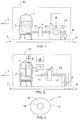
- Figure 1 schematically shows an apparatus for producing a road marking from a permanent marking material,
- Figure 2 schematically shows a second apparatus for producing a road marking from a permanent marking material, and
- Figure 3 schematically shows a detail of the apparatus.
-
For the sake of clarity, the figures show the invention in a simplified manner.
DETAILED DESCRIPTION OF THE INVENTION
-
Figure 1 shows an apparatus for producing a road marking from a permanent marking material schematically. The apparatus of Figure 1 comprises a tank 1, in which a batch of pre-produced permanent marking material mix 2 is placed. In the following, the term permanent marking material 2 or marking material 2 is used to refer to the permanent marking material mix. In connection with the tank 1 or in its immediate proximity or, in the solution of Figure 1, inside the outer casing of the tank there are means 3 for heating the marking material 2 in the tank 1 to a temperature, e.g. a temperature of 200 to 225°C, at which the marking material becomes a molten material which is transferable in liquid form. From the tank 1, the marking material 2 in liquid form is transferred in a relatively pressure-free state and pulled by underpressure produced by a high-pressure pump along a pipe section 11 to a filter 4 and further through it, in which filter 4 impurities of the marking material 2 are filtered away. The apparatus also comprises a high-pressure pump 5 operating with an operating pressure of approximately 100 to 300 bar, and an independent power engine, not shown in Figure 1 for the sake of clarity, for operating and rotating the hydraulic pump 5 and acting as a power source for a road marking machine. The high-pressure pump 5 pumps the marking material 2 coming from the filter 4 along the pipe section 11' to the pump 5 through a pipe section 11" to a nozzle 6 and further through the nozzle 6 directly onto a road surface 7 in such a manner that a few millimetre thick road marking 8 is typically formed on the road surface 7.
-
The above-mentioned machines may be arranged on a suitable base, such as a vehicle or a trailer, shown very schematically in Figure 1 by means of a broken line 10, whereby the base may either be transferred by means of power transmission equipment arranged in connection with the base, in which case it is typically a solution arranged on the base of a lorry, or, if the base is a trailer, the apparatus may be pulled by a vehicle connected to the trailer. In Figure 1, the direction of travel of the base is marked with arrow T.
-
In the apparatus of Figure 1, the marking material 2 is thus sprayed under high pressure produced by the high-pressure pump 5 directly to the nozzle 6 and further through the nozzle 6 onto the road surface 7, and an air compressor, which was earlier required for opening the nozzle 6 and/or spraying the marking material 2, need not be provided in the apparatus anymore. As a result, the structure of the apparatus according to the solution is simpler than previously. Since the apparatus does not comprise an air compressor anymore, the total weight of the apparatus becomes considerably smaller, fewer maintenance or reparation operations are needed and malfunctions caused by the compressor can be avoided. Consequently, the efficiency of the apparatus increases. Furthermore, the track of the road marking 8 looks cleaner than before, because the even stream of marking material achieved with the pump 5 is not scattered when it travels through the nozzle 6 as it does when the marking material 2 is sprayed by means of compressed air through the nozzle 6. In addition, the adjustment of the thickness of the road marking 8 to be produced is simpler and more precise. The thickness of the road marking 8 can be adjusted, for instance, by changing the operating pressure of the pump 5 or the flow rate of the marking material by means of a control unit 9 arranged in connection with the pump 5.
-
The high-pressure pump 5 can be a commercially available high-pressure pump with a normal structure. Due to the high temperature of the marking material 2, however, it is advantageous to make some changes to the pump and hoses or pipes starting from the pump. These changes include, for instance, replacing of seals with ones made of teflon and building of a protective casing filled with oil, for instance, around the pump and the hoses or pipes starting therefrom in such a manner that the structure of the apparatus becomes resistant to high temperatures without causing a danger to the surroundings. The protective casing is shown very schematically by means of a broken line 12 in the figure.
-
Figure 2 shows a second apparatus for producing a road marking from a permanent marking material schematically. In the apparatus of Figure 2, the high-pressure pump 5 is placed inside the tank 1. The high-pressure pump 5 supplies marking material 2 from the tank 1 via the pipe section 11 to the filter unit 4, in which impurities are removed from the marking material 2. Under the influence of the high-pressure pump 5, the marking material 2 is transferred from the filter unit 4 further along the pipe section 11' to the nozzle 6, from which the marking material 2 is sprayed onto the road surface.
-
In the solution of Figure 2, a high-pressure piston pump is used as a high-pressure pump 5. Figure 2 also shows a hydraulic power unit comprising a hydraulic pump 13 and one or more cylinders 14, which is/are connected to the high-pressure pump 5. The hydraulic pump 13 generates power for the cylinder 14, which is arranged to operate the high-pressure piston pump used as a high-pressure pump 5 by means of a piston arm of the cylinder. The power source for the hydraulic power unit 13 is a power engine 15, which may simultaneously act as a power source for the entire road marking machine.
-
Figure 2 further shows schematically by means of a broken line 12 an oil-filled protective casing placed around the high-pressure pump 5, the filter unit 4, the pipe sections 11 and 11' starting from the high-pressure pump 5 and the filter unit 4, and the nozzle 6. The protective casing not only protects the surroundings of the apparatus from high temperatures but also prevents heat losses of the permanent marking material 2 at high temperature and thus keeps the marking material 2 at operating temperature. Furthermore, a separate control unit 9 may also be arranged in connection with the high-pressure pump 5.
-
The high-pressure piston pump is used for achieving as even a working pressure as possible for supplying the mix to the nozzles, whereby it is easy to adjust the thickness of the mix to be applied, which makes the quality of the road marking to be produced uniform.
-
Figure 3 shows a cross-section of the pipe section 11 schematically. The pipe sections 11, 11' and 11" may be made of a pressure pipe or pressure hose having a suitable pressure and heat resistance. Figure 3 shows a cross-section of a suitable pressure hose. The pressure hose according to Figure 3 comprises an inner hose 16, which may be composed of a tef-Ion hose having a diameter of 0.5 inches (approximately 12.7 mm), for instance. The pressure hose of Figure 3 also comprises an outer hose or an outer cover 17, which may be composed of an all-metal hose having a diameter of 1.5 inches (approximately 38.1 mm), for instance. Between the inner hose 16 and the outer hose 17 there is an oil sump 18 for heat-transfer oil.
-
The marking materials 2 may be various granular marking material mixes known per se by a person skilled in the art, which are converted into a molten, liquid form when heated to a suitable temperature and which are composed of elastomers, resins, oil, titanium oxide and glass beads.
-
The apparatus according to the figure may also be provided with, for instance, means for adding a material, such as glass beads, enhancing the visibility or reflectivity of the road marking 8 to the road marking 8 either in such a manner that the reflective material is added to the marking material 2 before the marking material 2 is sprayed onto the road surface 7 or such that the reflective material is added onto the road marking 8 formed on the road surface 7. These means may thus comprise, for example, a tank for storing the reflective material, a stirrer for stirring the reflective material into the marking material 2, or a nozzle for spraying the reflective material onto the road marking 8 formed on the road surface 7.
-
The figure and the related description are only intended to illustrate the idea of the invention. In its details, the invention may vary within the scope of the claims.